patent · US4034569
Sorption system for low-grade (solar) heat utilization
12 July 1977
Page 1 — bibliographic record
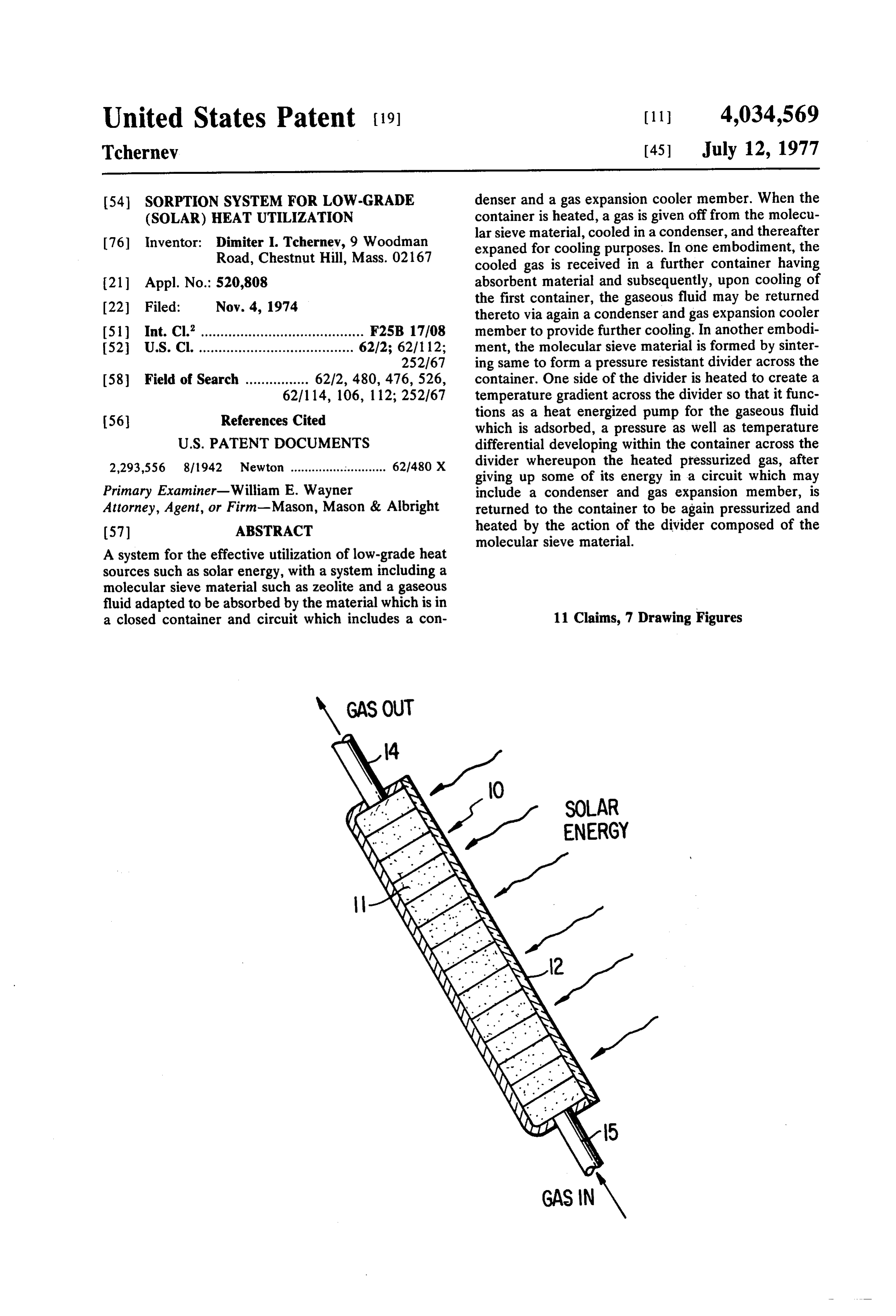
United States Patent (19) (11) 4,034,569 Tchernev (45) July 12, 1977 54). SORPTION SYSTEM FOR LOW-GRADE denser and a gas expansion cooler member. When the (SOLAR) HEAT UTILIZATION container is heated, a gas is given off from the molecu lar sieve material, cooled in a condenser, and thereafter 76 Inventor: Dimiter I. Tchernev, 9 Woodman expaned for cooling purposes. In one embodiment, the Road, Chestnut Hill, Mass. 02167 cooled gas is received in a further container having (21) Appl. No.: 520,808 absorbent material and subsequently, upon cooling of (22 Filed: Nov. 4, 1974 the first container, the gaseous fluid may be returned thereto via again a condenser and gas expansion cooler
I51) Int. Cl”......................................... F25B 17/08 member to provide further cooling. In another embodi 52 U.S. Cl. ....................................... 62/2; 62/1 12; ment, the molecular sieve material is formed by sinter 252/67 ing same to form a pressure resistant divider across the 58 Field of Search ................ 62/2, 480, 476,526, container. One side of the divider is heated to create a 62/114, 106, 1 12; 252/67 temperature gradient across the divider so that it func (56) References Cited tions as a heat energized pump for the gaseous fluid which is adsorbed, a pressure as well as temperature
2,293,556 81942 Newton ........................... 62/480 X divider whereupon the heated pressurized gas, after giving up some of its energy in a circuit which may
Primary Examiner-William E. Wayner include a condenser and gas expansion member, is Attorney, Agent, or Firm-Mason, Mason & Albright returned to the container to be again pressurized and (57) ABSTRACT heated by the action of the divider composed of the molecular sieve material.
A system for the effective utilization of low-grade heat sources such as solar energy, with a system including a molecular sieve material such as zeolite and a gaseous fluid adapted to be absorbed by the material which is in a closed container and circuit which includes a con 11 Claims, 7 Drawing Figures
Page 2
Drawing sheet — no readable text.
Page 3
Drawing sheet — no readable text.
Page 4
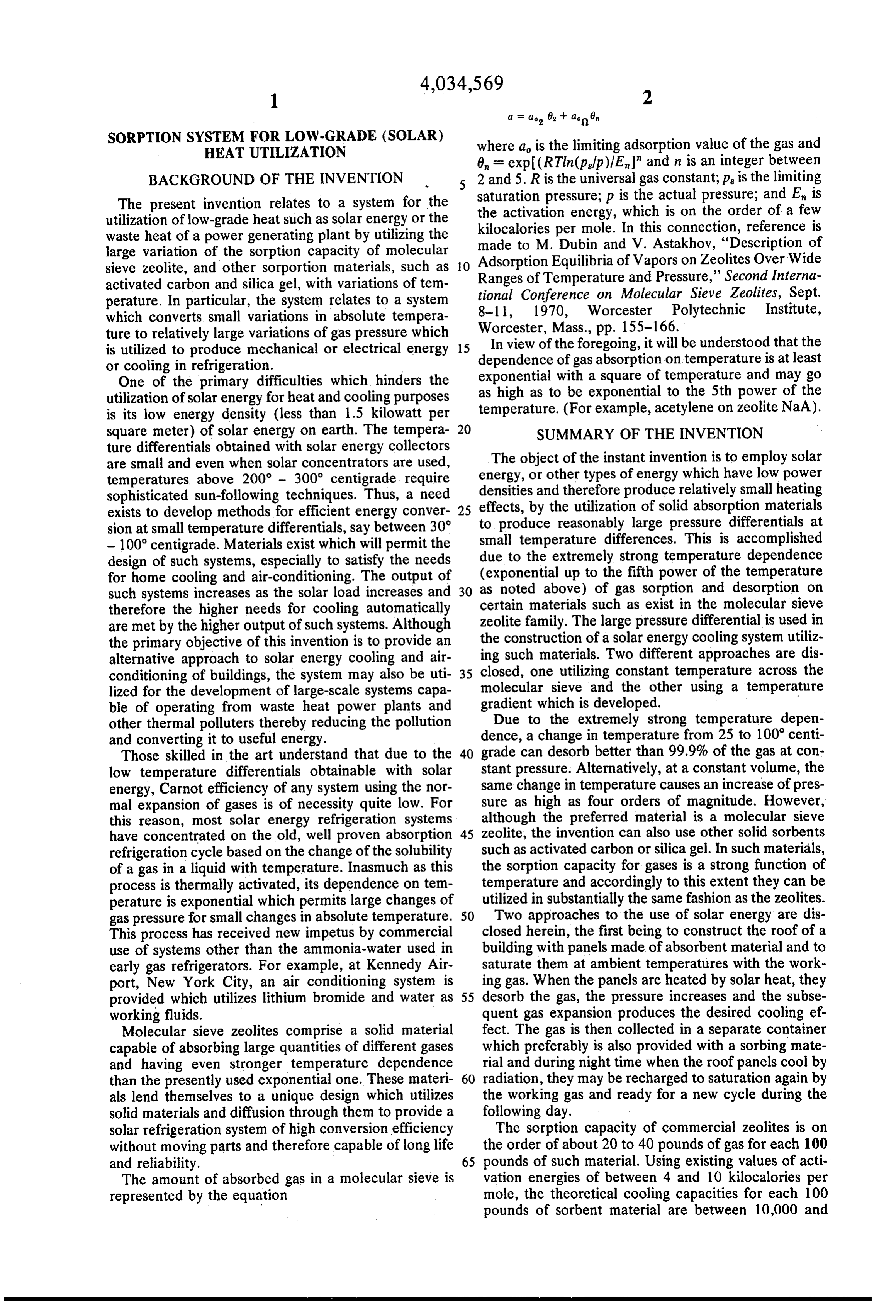
SORPTION SYSTEM FOR LOW-GRADE (SOLAR) where a is the limiting adsorption value of the gas and
HEAT UTILIZATION
6, = exp(RTln(p,fp)/E" and n is an integer between
BACKGROUND OF THE INVENTION 5 2 and 5. R is the universal gas constant; p is the limiting The present invention relates to a system for the saturation pressure; p is the actual pressure; and E is utilization of low-grade heat such as solar energy or the kilocalories perenergy, the activation which is on the order of a few mole. In this connection, reference is waste heat of a power generating plant by utilizing the made to M. Dubin and V. Astakhov, "Description of large variation of the sorption capacity of molecular Adsorption Equilibria of Vapors on Zeolites Over Wide sieve zeolite, and other sorportion materials, such as O Ranges of Temperature and Pressure,” Second Interna activated carbon and silica gel, with variations of tem perature. In particular, the system relates to a system tional Conference on Molecular Sieve Zeolites, Sept. which converts small variations in absolute tempera 8-1 1, 1970, Worcester Polytechnic Institute, ture to relatively large variations of gas pressure which Worcester, Mass., pp. 155-166. In view of the foregoing, it will be understood that the is utilized to produce mechanical or electrical energy 15 dependence of gas absorption on temperature is at least or cooling in refrigeration. exponential with a square of temperature and may go One of the primary difficulties which hinders the as high as to be exponential to the 5th power of the utilization of solar energy for heat and cooling purposes temperature. (For example, acetylene on zeolite NaA). is its low energy density (less than 1.5 kilowatt per square meter) of solar energy on earth. The tempera 20 SUMMARY OF THE INVENTION ture differentials obtained with solar energy collectors The object of the instant invention is to employ solar are small and even when solar concentrators are used, temperatures above 200 - 300 centigrade require energy, or other types of energy which have low power sophisticated sun-following techniques. Thus, a need densities and therefore produce relatively small heating exists to develop methods for efficient energy conver 25 toeffects, by the utilization of solid absorption materials sion at small temperature differentials, say between 30 produce reasonably large pressure differentials at - 100 centigrade. Materials exist which will permit the duesmall temperature differences. This is accomplished design of such systems, especially to satisfy the needs to the extremely strong temperature dependence for home cooling and air-conditioning. The output of (exponential up to the fifth power of the temperature as noted above) of gas sorption and desorption on such systems increases as the solar load increases and 30 certain therefore the higher needs for cooling automatically materials such as exist in the molecular sieve are met by the higher output of such systems. Although zeolite family. The large pressure differential is used in the primary objective of this invention is to provide an the construction of a solar energy cooling system utiliz alternative approach to solar energy cooling and air ing such materials. Two different approaches are dis conditioning of buildings, the system may also be uti 35 closed, one utilizing constant temperature across the lized for the development of large-scale systems capa molecular sieve and the other using a temperature ble of operating from waste heat power plants and gradient which is developed.
other thermal polluters thereby reducing the pollution Due to the extremely strong temperature depen and converting it to useful energy. dence, a change in temperature from 25 to 100 centi Those skilled in the art understand that due to the 40 grade can desorb better than 99.9% of the gas at con low temperature differentials obtainable with solar stant pressure. Alternatively, at a constant volume, the energy, Carnot efficiency of any system using the nor same change in temperature causes an increase of pres mal expansion of gases is of necessity quite low. For sure as high as four orders of magnitude. However, this reason, most solar energy refrigeration systems although the preferred material is a molecular sieve have concentrated on the old, well proven absorption 45 zeolite, the invention can also use other solid sorbents refrigeration cycle based on the change of the solubility such as activated carbon or silica gel. In such materials, of a gas in a liquid with temperature. Inasmuch as this the sorption capacity for gases is a strong function of process is thermally activated, its dependence on tem temperature and accordingly to this extent they can be perature is exponential which permits large changes of utilized in substantially the same fashion as the zeolites. gas pressure for small changes in absolute temperature. 50 Two approaches to the use of solar energy are dis This process has received new impetus by commercial closed herein, the first being to construct the roof of a use of systems other than the ammonia-water used in building with panels made of absorbent material and to early gas refrigerators. For example, at Kennedy Air saturate them at ambient temperatures with the work port, New York City, an air conditioning system is ing gas. When the panels are heated by solar heat, they provided which utilizes lithium bromide and water as 55 desorb the gas, the pressure increases and the subse working fluids. quent gas expansion produces the desired cooling ef. Molecular sieve zeolites comprise a solid material fect. The gas is then collected in a separate container capable of absorbing large quantities of different gases which preferably is also provided with a sorbing mate and having even stronger temperature dependence rial and during night time when the roof panels cool by than the presently used exponential one. These materi 60 radiation, they may be recharged to saturation again by als lend themselves to a unique design which utilizes the working gas and ready for a new cycle during the solid materials and diffusion through them to provide a following day.
solar refrigeration system of high conversion efficiency The sorption capacity of commercial zeolites is on without moving parts and therefore capable of long life the order of about 20 to 40 pounds of gas for each 100 and reliability. 65 pounds of such material. Using existing values of acti The amount of absorbed gas in a molecular sieve is vation energies of between 4 and 10 kilocalories per represented by the equation mole, the theoretical cooling capacities for each 100 pounds of sorbent material are between 10,000 and
Page 5
20,000 BTU's. Thus, it will be appreciated that the DESCRIPTION OF THE PREFERRED existing roof area of a typical house is sufficient for a EMBODEMENTS reasonably efficient cooling system.
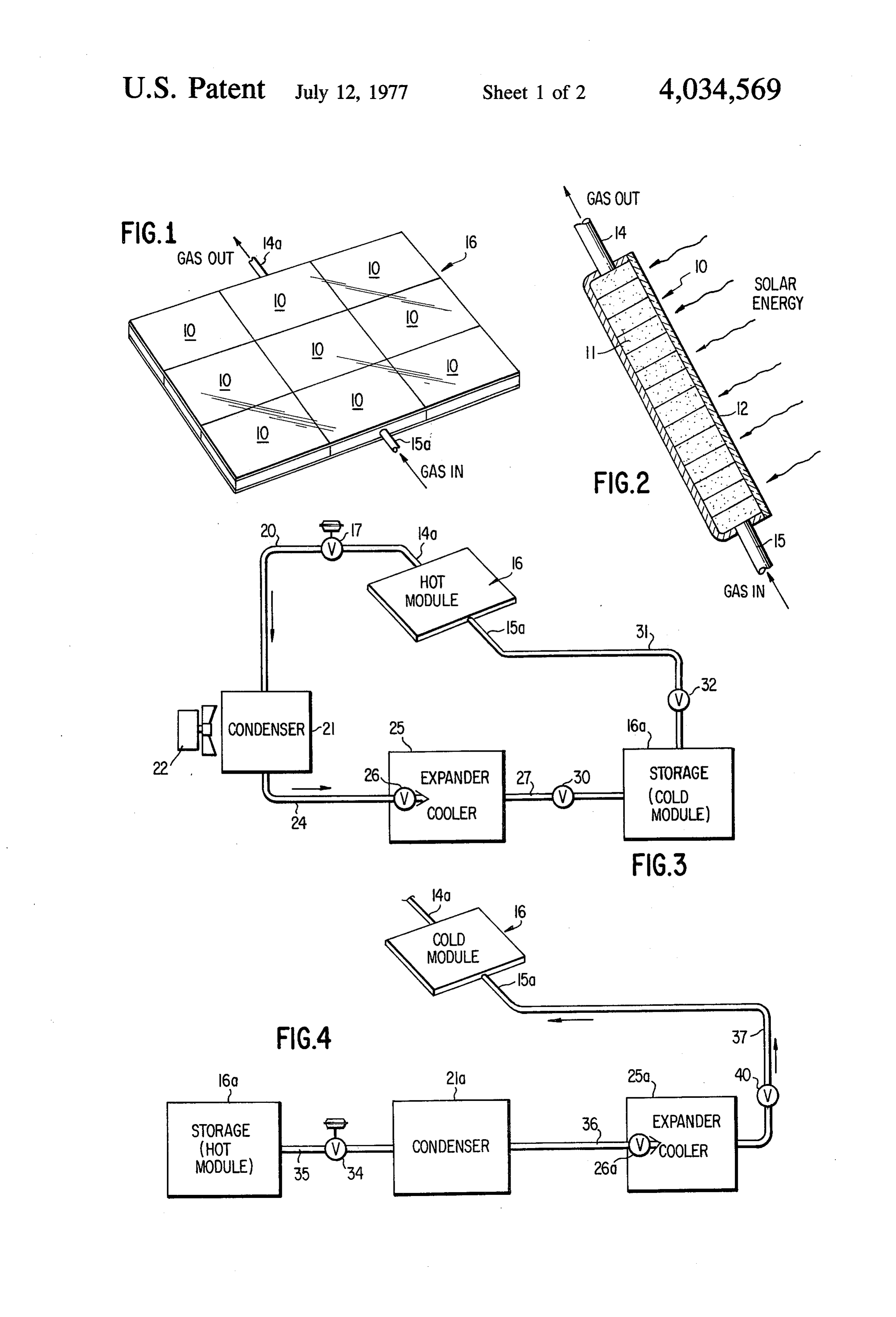
The roof panels may be made by pressing and sinter Referring now to FIGS. 1-4, a container 10 com ing the molecular sieve materials into the proper shape 5 posed of metal or other heat conductive material pref and sealing them in a container capable of withstanding erably has a honeycomb structure which is filled with pressure. Two types of containers are disclosed herein: zeolite 11 or other appropriate absorbent material. one with a glass cover in which the solar energy is Surface 12 of container 10 is darkened so that it ab absorbed directly by the molecular sieve panel which sorbs as much solar energy as practicable. It will be has preferably been darkened on one surface with, for 10 noted container 10 is provided with a gas outlet 14 and example, carbon black to increase the absorption of a gas inlet 15. It is to be understood that the cross-sec solar energy; the other container is constructed com tional view disclosed in FIG. 2 is representative of a pletely of a darkened metal and absorbed energy is number of panels such as indicated in FIG. 1 which can conducted to the absorbent material on the interior by be installed on the roof of a house or any other surface a structure similar to the familiar honeycomb structure 5 illuminated by the sun. The individual panels 10 are combined into a module 16 into which the gas outlets which surrounds the molecular sieve on all sides. Al though this latter structure uses indirect heating of the 14 14a are connected together in an outlet for the module and in a like manner the gas inlets 15 are con molecular sieve material, it is capable of higher work nected together to form gas inlet for the module 15a. ing pressures and, therefore, of higher operating effi 20 Each module 16 connects with a oneway valve 17, the ciency. valve 17 being pressure controlled to open when the In view of the foregoing, the primary object of this pressure in module 16 builds up to a selected amount. invention is the provision of a system for the utilization The outlets 14a through an appropriate manifold, lead of low grade heat such as solar heat or the waste heat of into a first conduit or line 20 which connects to the a power generating plant and the like by utilizing a 25 intake of a condenser 21 which is cooled by a fan 22. large variation of sorption capacity of molecular sieve From the outlet of condenser 21, a second conduit or zeolites or other sorption materials such as activated line 24 connects to the inlet of a gas expander cooler carbon and silica gel, whereby with variations in tem member 25 which includes an expansion valve 26. It perature the system converts small variations in abso will be understood by those skilled in the art that the lute temperature to large variations in gas pressure for 30 cooler member 25 can be connected to the building's the subsequent utilization for cooling in refrigeration or air conditioning to provide cooling therefor. From the other energy uses. cooler member 25 a third line or conduit 27 serves to A further object of the invention is to provide the convey fluid through a one-way valve 30 into a con above system to produce a cyclic heating of the sorbent fined space which can be a cold module 16 which is material so that the gas flows from the hot to the cold 35 designated 16a in FIG. 3. Alternatively, the can con sorbent under pressure thus generating the desired tainer 16a may be an empty gas container also, if de energy, sired, filled with a zeolite material in order to minimize A further object is to create a temperature gradient the volume which would otherwise be necessary. across the sorbent material which produces a pressure 40 When the modules 16 are heated, the gas in the zeo differential with the gas flowing from the hot to the lite material 11 is desorbed and pressure builds up in cold side of the sorbent material via an external ar container 10. When an upper threshold as set by the rangement wherein energy is used and from the cold to flows one-way valve 17 is exceeded, valve 17 opens and gas the hot side through the material thus creating a contin via outlet 14a in the first line 20 to the condenser uous gas flow at a pressure differential and, accord 45 21 which may be cooled by the fan 22 as shown or ingly, continuous use of the energy resulting from the water cooled. The working gas is cooled in condenser pumping effect across the absorbent material which is then 21 where it may be converted into a liquid fluid and relatively heated on one side only. conveyed via the second line 24 to the cooler member 25. Here the gas expands (or the liquid fluid
Further objects, adaptabilities and capabilities will evaporates appear as the description progresses, reference being 50 the cooler member into a gas) while at the same time cooling had to the accompanying drawings, in which: 25. As indicated above, the cooling effect is preferably used at this point in a conventional
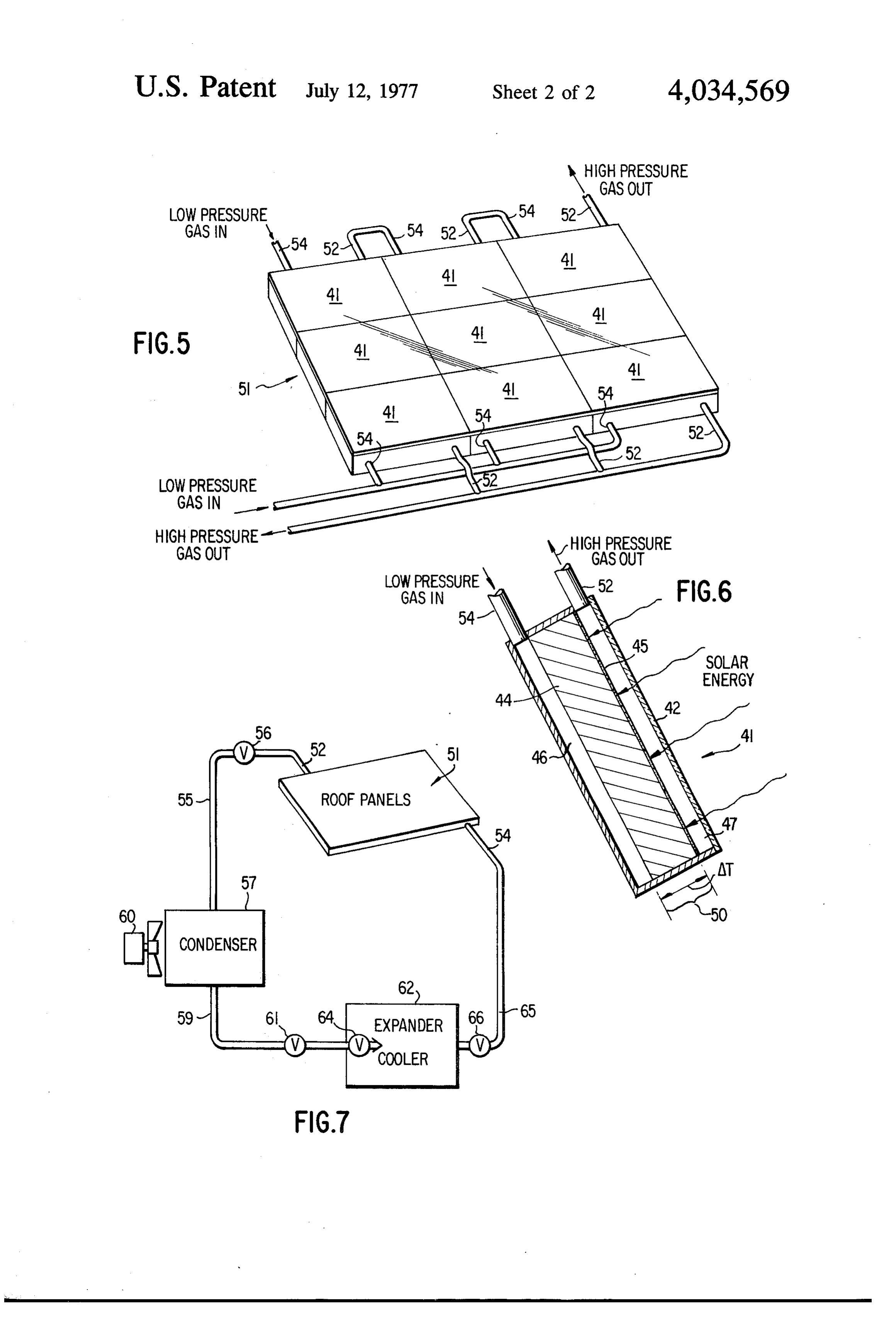
BRIEF DESCRIPTION OF THE DRAWINGS way for air-conditioning or refrigeration or the like. FIG. 1 is a perspective view illustrating a group of one-wayThe gas then passes through the third line 27 and the panels in accordance with the invention; valve 30 into the storage space 16a. As previ 55 ously indicated, storage area 16a be a module identical
FIG. 2 is a cross-section of one of the panels shown in to module 16 except that at a particular time it is not
FIG. 3 is a systemic diagram showing the day opera exposed
It will to the direct rays of the sun.
be understood that as long as the zeolite in the tion or hot side of the gaseous circuits; module 16 is warmer than the gas or zeolite in the FIG. 4 is a systemic diagrammatic representation of 60 storage space 16a the flow of the gas will be from mod the night operation or cold side of the system; ule 16 via condensor 21 and cooler member 25 into the FIG. 5 shows a group of panels of a further embodi storage area 16a. The next cycle of the operation takes ment of the invention; place when the module 16 is no longer being heated FIG. 6 is a cross-section of one of the panels shown in such as, for example, being on the shady side of the FIG. 5; and 65 house, or shaded by some other means, or the sun has FIG. 7 is a systemic diagrammatic representation of a set for the night. In such event, module 16 is thereafter circuit which uses roof panels in accordance with the cooled by radiation and develops a low pressure in the latter embodiment. interior of the container 10. In such event, there are
Page 6
several variations of what may occur. For example, in a version into mechnical or electrical energy by conven desert climate when the days are hot and the nights are tional means utilizing reciprocal engines or turbines cool, the storage space 16a may be buried or otherwise and electric generators. In such a case, the invention of insulated and as indicated in FIG. 3, directly connected the cyclic heating and cooling of the module 16 and to the inlet 15a and the module 16 via a conduit or line storage space 16a is obtainable by proper valving of the 31 containing a one-way valve 32. However, if the waste heat from the source to the heat exchangers for evenings are also warm, then air conditioning during the zeolite material.
the night may be desired in which case the arrangement The approach described above takes advantage of disclosed in FIG. 4 is more desirable. It will be appreci the cyclic character of solar energy during the day ated that FIG. 4 thus shows the return cycle of the gas 10 night period to achieve a pumping effect without the from the storage space 16a to the module 16 which is use of compressors or other moving parts. It thus has a now cooled. potential for a long maintenance free life. However, it The storage space 16a connects through a fourth line either has to be designed for the largest possible inte or conduit 35 which contains a one-way pressure regu grated sun load during a complete day and therefore lated valve 34 similar to valve 17 which is set to permit 15 will be operating below its maximum capacity most of the passage of gas from the storage space 16a at a the time or should be augmented by alternative cooling predetermined pressure differential. Conduit 35 con methods during days of maximum heat.
nects into a condenser 21a which may be the same or a A second approach to the problem of maximum ca different condenser than condenser 21. The outlet pacity which results in a reduction in both the size and from condenser 21a constitutes a fifth line or conduit 20 cost of the complete system will now be described. This 36 which leads into the expansion valve 26a of a cooler approach is based on the circumstance that when a member 25a which, again, can be the same as cooler thermal gradient is applied across a piece of absorbing member 25 in which case one-way valve 30 should be material, the consequence is essentially a pumping provided with a second outlet leading back to the mod action. Although this has been known for materials ule 16 controlled by the relative pressure between the 25 having a diffusion coefficient which is thermally acti module 16 and the pressure in the storage space 16a, as vated, the situation is substantially different in the fam would occur to one skilled in the art. In this connection ily of molecular sieve materials. it will be noted that a sixth line or conduit 37 connects Molecular sieve zeolites have a crystal structure of the outlet of the cooler member 26a and the inlet 15 of intracrystalline pores in the form of large cavities (in the module 16. In line 37 a one-way valve 40 is pro 30 the molecular sense) linked by large or small shared vided. As indicated, valve 40 and valve 30 can be incor windows. For this reason the motion of a gas molecule porated in a single valve preferably controlled in the consists of a thermally activated “sticking' to the in event condenser 21a and coolant member 25a are the side of the cavities and a second energy barrier for same as condenser 21 and coolant member 25, respec diffusion through the windows between cavities. This tively. The condenser 21a may, as condenser 21, be 35 second process is responsible for the sifting action of cooled by a fan, cooling water, or other appropriate the molecular sieves whereby gases with molecular eaS dimensions less than the window size pass through the In the cycle wherein the module 16 is cool and the sieve whereas gases with molecular sizes larger than the gaseous fluid therein is at a less pressure than that in windows do not pass. In addition, molecules with large the storage space 16a, an appropriate pressure differ 40 electric dipole moment usually "stick' to the cavities ential builds up, valve 34 opens and the gaseous fluid (water for example) in contrast to atoms and molecules flows into the condenser 21a wherein it is cooled. Then without such moment - for example the noble gases - the working fluid as a gas or liquid flows into the cooler which do not stick to the cavities and their motion is member 25a wherein it is expanded by means of the controlled only by their relative size vis-a-vis the size of expansion valve 26a and cools in such a manner that it 45 the windows. For these reasons, motion of gases can be utilized for the air-conditioning or cooling sys through molecular sieves resembles diffusion only tem of a building or for refrigerations or for the like. slightly and is considerably more complex. Finally, the module 16 is recharged again with the In trials with a zeolite, Linde type 4A, panels were working gas and for the next cycle. sintered with a Kaolin binder. With one side of such It will be understood that the cycles can take place, 50 panels being heated to about 100 centigrade, a pump one during the day and the other during the evening, ing action was observed with a variety of different or, where the modules are placed on different sides of working gases. Such gases included CO, Freon-11 the building then one cycle may take place during the (CClF), Freon-12 (CCLF), Freon-21 (CHCF), morning and the next cycle during the afternoon and Freon-22 (CHCIF), water vapor, NH, SO, and N, evening. In the latter event, the cycle can be arranged 55 and O.
so that the gas flows from hot modules 16 on the east In the embodiment of the invention being discussed, ern aspect of a building or roof to cool modules 16 on the glass covered container 41 is used and the panel 44 the western aspect of the building or roof, then when is utilized as a divider to separate the container into the latter cooled modules become heated, the flow may separated pressure vessels which compares with the be to a storage space, and finally during the evening or 60 first approach wherein the zeolite did not form a pres night back to the first modules which are on the eastern sure barrier and thus the inlet and outlet portions of the aspect of the roof of the building. container 10 were, in effect, at all times at approxi Alternatively, the heat for module 16 may be sup mately the same pressure.
plied via a heat exchanger from the waste heat of a Referring now to FIGS. 5-7, it is to be noted that power plant, incinerator or other source of heat pollu 65 metal container 41 with a transparent cover 42 con tion rather than from solar heating. It will also be un tains the sintered zeolite divider 44. The side 45 of the derstood by those skilled in the art that the energy of zeolite 44 facing the sun is darkened by an appropriate the expanding gas is also capable of utilization for con means, for example with carbon black. Container 41 is
Page 7
divided in two halves, a rear one 46 containing a low containers, a solid absorbent material contained in at pressure, low temperature gas and a forward casing 47 least said first container, said first container being lo which contains the high pressure, high temperature cated where it is periodically heated by a low-grade working gas. When heat from the sun or other source heat source relative to said second container whereby heats the side 45 of zeolite 41, it creates a temperature the said absorbent material in said first container has a gradient AT which is designated by reference numeral relative temperature higher than said second container 50 in FIG. 6. The inner molecular pumping action of for a period of time and during a further period of time the zeolite barrier 44 described above creates a pres the absorbent material in said first container has a sure differential between the rear half 46 of the con lower relative temperature than said second container, tainer 41 and the forward casing 47. This pressure 10 a closed circuit between said containers, a gaseous fluid differential is then used to produce the desired energy adapted to be absorbed by said absorbent material in expenditure of the system. said circuit and said first container, said circuit includ In a module 51 shown in FIG. 5, the individual panels ing a first line from said first condenser to a first con 41 have their outlets 52 and inlets 54 connected in denser, a second line from said first condenser to a first series as illustrated in the upper part of FIG. 5 in order 15 gas expansion cooler means, a third line from said gas to obtain higher pressure or in parallel as indicated in expansion means to said second container, a fourth line the lower portion of FIG. 5, for a greater flow rate, or from said second container to a second condenser, a in a combination thereof. fifth line from said second condenser to a second gas As shown in FIG. 7, the module 51 has its outlet 52 expansion cooler means, and a sixth line from said connected to a first conduit 55 via a one-way valve 56 20 second gas expansion cooler means to said first con which leads into a condenser unit 57 which can be tainer.
cooled by fan 60 or other appropriate cooling means. 2. A sorption system in accordance with claim 1 The outlet of condenser 57 carries the working gas wherein said first container has an outlet therefrom through a conduit 59 into a cooler member 62 via a included in said first line and an inlet thereto included one-way valve 61. In the cooler member 62, the gas is 25 in said sixth line, oneway valves being included in said expanded by means of an expansion valve 64 whereby first and sixth lines.
it becomes very cool and may be utilized for air-condi 3. A sorption system in accordance with claim 2, tioning, refrigeration or the like. The resulting fluid is wherein said second container has an inlet thereto then collected and returned via a return conduit 65 to included in said third line and an outlet therefrom in the low pressure gas inlet 54 of the module 51 via a 30 cluded in said fourth line, oneway valves being in one-way valve 66 which is contained in the conduit 65. cluded in said third and fourth lines. Thus, as may be seen in the above-described appara 4. A sorption system in accordance with claim 3, tus FIGS. 5-7, the working gas from the high pressure wherein a single expansion cooler means is provided in casing 47 is conveyed from the high pressure outlet 52 the system through a one-way valve 56 and conduit 55 to the con 35 cooler meanswhich when comprises said first gas expansion the pressure of said gas at the outlet denser unit 57 where the gas is cooled by air from fan of said first container 60 or cooling water or other suitable means. The gas said gas at the inlet of issaidgreater than the pressure of now cooled (which may be in a liquid form) is con second gas expansion cooler means container second when the and said pressure veyed from condensor 57 into cooler member 62 where it produces cooling or refrigeration by expansion via 40 of said gas is greater at the outlet of said second con the expansion valve 64. The resulting low pressure gas tainer than at the inlet of said first container. is then conveyed through the conduit 65 via the one whereinsorption
a single system in accordance with claim 3, condenser is provided in the system way valve 66 back to the low pressure half 46 of con which comprises said first condenser when the pressure tainer 41 through the low pressure gas inlet 54. of said gas at the outlet of said first container is greater In absolute pressure, the following pressure differen 45 tials have been found operable with the gases: Freon than the pressure of said gas at the inlet of said second 11, 3/18 psi; Freon-12, 26/107 psi; Freon-21, 5/51 psi; container of said gas and said second condenser when the pressure is greater at the outlet of said second con
12/66 psi; CO, 332/1043 psi; and NH 35/170 psi. tainer than at the inlet of said first container. This last-described embodiment has the advantage of 50 6. A sorption system in accordance with claim 1, being capable of reusing the same volume of gas over wherein said heat source comprises solar energy. and over again during a given day and having a cooling 7. A sorption system in accordance with claim 1, output which is directly proportional to the solar heat wherein said heat source comprises a heated fluid. load. Thus, the larger the solar heat load, the greater is 8. A sorption system in accordance with claim 7, the cooling action which results. 55 wherein said heat source comprises a heated gas. Both approaches have advantage over the conven 9. A sorption system in accordance with claim 1, tional sorption cooling systems in that they have poten wherein said absorbent material is composed of zeolite. tially higher efficiencies because of the much stronger 10. An efficient system for a low-grade heat utiliza temperature dependence of the sorption process. In tion which converts small variations in absolute tem addition, there is no need for mechanical moving parts 60 perature to relatively larger variations of gas pressure, inasmuch as the system consists only of solid panels, the system comprising:
pressure vessels and conduits, and the working gas - is a hermetically sealed container, said container hav thus, offering high reliability and a long operating life. ing an inlet and an outlet each with a one-way Having thus described my invention, what I claim as valve;
new and desire to secure by Letters Patent of the 65 a solid absorbent material composed of molecular United States is: sieve Zeolite in said container, said absorbent mate 1. A sorption system for low-grade heat utilization rial adapted to absorb an expansible fluid which which comprises first and second hermetically sealed enters said container through said inlet when rela
Page 8
tively cool and to expel said fluid through said heat energy utilization means connected to said out outlet when relatively heated; 11.let.A system for a low-grade heat utilization in accor a low-grade heating means adapted periodically to dance with claim 10, wherein said heat energy utiliza raise the temperature of said absorbent material; 5 tion means comprises a condenser and a gas expansion a source of gaseous fluid adapted to be absorbed by cooler means for cooling said gas. said absorbent material available to said inlet; and ck k k k
Provenance
- Collection
- Cited prior art
- Original PDF
- patentimages.storage.googleapis.com →
- Filed
- 1974-11-04
- Pages
- 8
- Method
- pdftotext (the PDF's own text layer) + pdftoppm 300dpi page scans
- Source
- Google Patents bibliographic record
- Granted
- 1977-07-12
- Inventors
- Dimiter I. Tchernev
- Transcribed from
- patentimages.storage.googleapis.com →