patent · US5305714
Fuel supply system for an internal combustion engine
26 April 1994
Page 1 — bibliographic record
United States Patent (19) 11 Patent Number: 5,305,714 Sekiguchi et al. 45 Date of Patent: Apr. 26, 1994 54 FUELSUPPLY SYSTEM FOR AN INTERNAL 5,067,447 11/1991 Iwaki et al. ............................. 123/3 COMBUSTON ENGINE 5,082,048 1/1992 Iwaki et al. ............................. 123/3 75 Inventors: Kiyonori Sekiguchi, Okazaki; FOREIGN PATENT DOCUMENTS Toshihiko gashira, Toyokawa; Kenji 61-220009 9/1986 Japan.
Kanehara, Toyohashi; Nobuo 63-246459 10/1988 Japan.
natake, Nishio; Jun Yamada; 1-216024 8/1989 Japan .
Nobuyuki Murate, both of Okazaki; 3-961 1/1991 Japan.
Osamu Kito, Nisshin, all of Japan Primary Examiner-Noah P. Kamen 73) Assignees: Nippon Soken, Inc., Nishio; Toyota Assistant Examiner-Erick Solis Jidosha Kabushiki Kaisha, Toyota, Attorney, Agent, or Firm-Cushman, Darby & Cushman both of Japan 57. ABSTRACT 21 Appl. No.: 908,270 A fuel supply system for a hydrogen gas engine, having 22 Filed: Jul. 2, 1992 a metal hydride tank in which pellets or powders of a 30 Foreign Application Priority Data metal hydride absorbing and storing alloy are stored. A heat exchange device is arranged in the tank in contact
Jul. 3, 1991 (JP) Japan .................................. 3-162844 with the metal hydride therein. The heat exchange Oct. 1, 1991 (JP Japan. ... 3-253.737 device is connected to a heating medium source, such as Feb. 7, 1992 (JP Japan. ... 4-022725 an engine water jacket, for supplying the heating me Feb. 14, 1992 JP Japan .................................. 4028058 dium to the heat exchange device, for separating hydro 51 int.C. .............................................. FO2B 43/08 gen gas from the metal hydride. A fuel supply conduit 52 U.S. C. ................................ 123/3; 123/DIG. 12 is provided for connecting the metal hydride tank with 58 Field of Search .................. 123/3, DIG. 12, 1 A, the engine. A hydrogen gas flow control valve and a 123/527 hydrogen gas flow meter are arranged in series in the 56) References Cited conduit. A controller is provided for controlling the hydrogen gas flow control valve so that a desired
4,016,836 4/1977 MacKay et al......................... 23/3 gen gas flow meter, is obtained. A sub tank may be 4,018,190 4/1977 Henault................................... 123/3 provided for storing an excess amount of hydrogen gas 4,178,882 12/1979 Anderson et al. ...................... 123/3 from the main tank, which is introduced into the engine 4,211,537 7/1980 Teitel ...................................... 123/3 via a sonic valve. An indicator for measuring an amount 4,214,699 7/1980 Buchner et al. ... . 123/1 A of hydrogen gas remaining, from the volume of the 4,225,320 9/1980 Gell ......................................... 123/3 4,290,267 9/198 Buchner et al. ........................ 23A3 metal hydride, is also provided. 4,302,27 li/1981 Teite et al. ............................. 1.23/3 5,027,780 3/1991 Sekiguchi et al. .................. 123/520 23 Claims, 15 Drawing Sheets
Page 2
Drawing sheet — no readable text.
Page 3
Drawing sheet — no readable text.
Page 4
Drawing sheet — no readable text.
Page 5
Drawing sheet — no readable text.
Page 6
Fig 6
READ OPERATING
CALCULATE BASIC HYDROGEN
AMOUNT Qbose 218 DETECT SUBTANK PRESSURE Po CALCULATE FINAL
AND INTAKE PRESSURE P HYDROGEN AMOUNT
Qfins Qbose
IS STOPPER VALVE 92
OPEN ?
Pimax / PogP/PoMAX 2
OPEN STOPPER CLOSE STOPPER
YES
CAL CULATE FINAL HYDROGEN
AMOUNT
Qfins Obose- Qs
ISSUE Ofin
Page 7
Drawing sheet — no readable text.
Page 8
Drawing sheet — no readable text.
Page 9
Drawing sheet — no readable text.
Page 10
Drawing sheet — no readable text.
Page 11
Drawing sheet — no readable text.
Page 12
Drawing sheet — no readable text.
Page 13
Drawing sheet — no readable text.
Page 14
Drawing sheet — no readable text.
Page 15
Drawing sheet — no readable text.
Page 16
Drawing sheet — no readable text.
Page 17
control device and the flow control device are operated
FUEL SUPPLY SYSTEM FOR AN INTERNAL in accordance with the pressure values detected by the COMBUSTON ENGINE pressure sensors, to thus obtain a required control of the pressure and flow amount of the hydrogen gas.
BACKGROUND OF THE INVENTION 5 In a prior art hydrogen engine provided with a metal 1. Field of the Invention hydride tank, as also seen from the above-mentioned The present invention relates to a fuel supply system first and second prior arts, the control of the amount of for an internal combustion engine. the hydrogen gas is executed by a predetermined heat 2. Description of the Related Art ing or cooling of the metal hydride material, and the Attempts have long been made to use hydrogen as a 10 obtained hydrogen gas is introduced, via a pressure fuel for an internal combustion engine, but such at regulator device, to a carburetor or to fuel injection tempts were abandoned. Recently however, interest in valves of the internal combustion engine. The pressure these attempts has been revived due to the finding that regulator mounted in a fuel supply conduit between the hydrogen produces a low amount of toxic emissions, fuel tank and the carburetor or fuel injection valves is which is advantageous from the view point of protect 15 provided for maintaining a predetermined constant ing the environment, and due to the urgent need for the pressure of the hydrogen gas in the conduit. Such a development of new fuel resource because of the loom control of the hydrogen pressure by the regulator is ing shortage of fossil fuels in the near future. In an auto essential for obtaining a desired amount of hydrogen by mobile using hydrogen as a fuel, a fuel tank having a controlling the duration of the time for which the fuel high pressure resistance and a cylindrical shape, in injection valves are open, without actually detecting which liquid hydrogen is stored, is usually employed. the amount of hydrogen gas. Such a fuel supply system, Such a high pressure type tank, however, is disadvanta however, suffers from the following drawbacks. geous from the view point of easy handling, and there The regulator in the hydrogen supply conduit con fore, a new construction of a fuel tank has been pro 25 necting the metal hydride tank with the fuel injectors posed, in place of the high pressure type, wherein a can suffer from a large pressure loss across the regula hydrogen absorbing and storing alloy, such as Ti-Fe, is charged in a tank as fine pellets or powders thereof, and tor, compared with a gasoline engine, and this makes it difficult for the hydrogen engine to quickly obtain an gaseous hydrogen is absorbed by the Ti-Fe pellets to amount of provide a metal hydride stored in the pellets. Heating has a smallhydrogen molecular gas required. Namely, hydrogen weight, and therefore, with re the pellets causes the hydrogen gas to be separated 30 spect to the same amount therefrom. The hydrogen gas can thus be supplied to an internal combustion engine, of air introduced into the a large volumetric amount internal combustion engine. The handling of such a of the hydrogen gas must be introduced when com system using Ti-Fe pellets is relatively easy, compared pared with a high density hydrocarbon fuel such as with that of a high pressure hydrogen tank, because a gasoline. Such a large volumetric amount of the hydro relatively large amount of high density hydrogen can be 35 stored under a relatively small pressure. gen gas creates a large pressure loss across the regulator Japanese Unexamined Patent Publication No. when the gas is passed therethrough, and therefore, upon an acceleration of the engine, the amount of hy 61-220009 discloses a tank to be charged with the metal drogen required by the engine is increased but the large hydride pellets. This tank is equipped with a system for maintaining a predetermined constant pressure inside pressure loss makes it difficult for the necessary amount the metal hydride tank regardless of a change in a load of hydrogen gas to be quickly supplied to the engine, on the internal combustion engine, and the system is and thus the performance of the engine is degraded. constructed by a pressure sensor for detecting a pres SUMMARY OF THE INVENTION sure of the hydrogen gas in the tank, and an electric control device for calculating a pressure change in ac 45 An object of the present invention is to provide a fuel cordance with a lapse of time, i.e., a pressure gradient. supply system for a hydrogen engine, whereby a quick A flow control valve is further provided and is respon control of a supply of a desired amount of hydrogen gas sive to a calculated pressure gradient for controlling an required by the engine is obtained. amount of hot engine cooling water fed from the engine According to the present invention, a fuel supply to the tank, for heating the metal hydride, to thus con 50 system for an internal combustion engine is provided trol the amount of hydrogen gas separated from the wherein hydrogen gas is used as the fuel, said system pellets stored in the tank. comprising:
In Japanese Unexamined Patent Publication No. a fuel tank in which a metal hydride is stored; 1-216024, the metal hydride tank is provided with a a heat exchange device arranged in said fuel tank for temperature sensor, in addition to the pressure sensor. 55 controlling a temperature of the metal hydride in the Furthermore, in addition to a main metal hydride tank, tank;
an auxiliary tank is provided and arranged in parallel to first control means for controlling an amount of heat the main tank, and a switching valve is located in a pipe ing medium introduced into the heat exchange device to the tanks, for controlling a selective introduction of so that a desired amount of hydrogen gas is generated the hot engine water to the tanks. A warning device is 60 from the metal hydride in the tank; further provided for sounding an alarm when the a fuel supply conduit connecting the fuel tank with amount of hydrogen remaining in the tank becomes too the internal combustion engine for introducing the hy small, to thus prevent a situation such that the fuel sup drogen gas into the engine, and; ply is abruptly stopped while the vehicle is running. second control means for controlling an amount of This prior art is provided with a plurality of pressure 65 hydrogen gas flowing in the fuel supply conduit so that sensors arranged in gas passageways running from the a desired amount of hydrogen gas is introduced into the tank to the internal combustion engine, a pressure con engine in accordance with an operating condition of the trol device, and a flow control device. The pressure engine.
Page 18
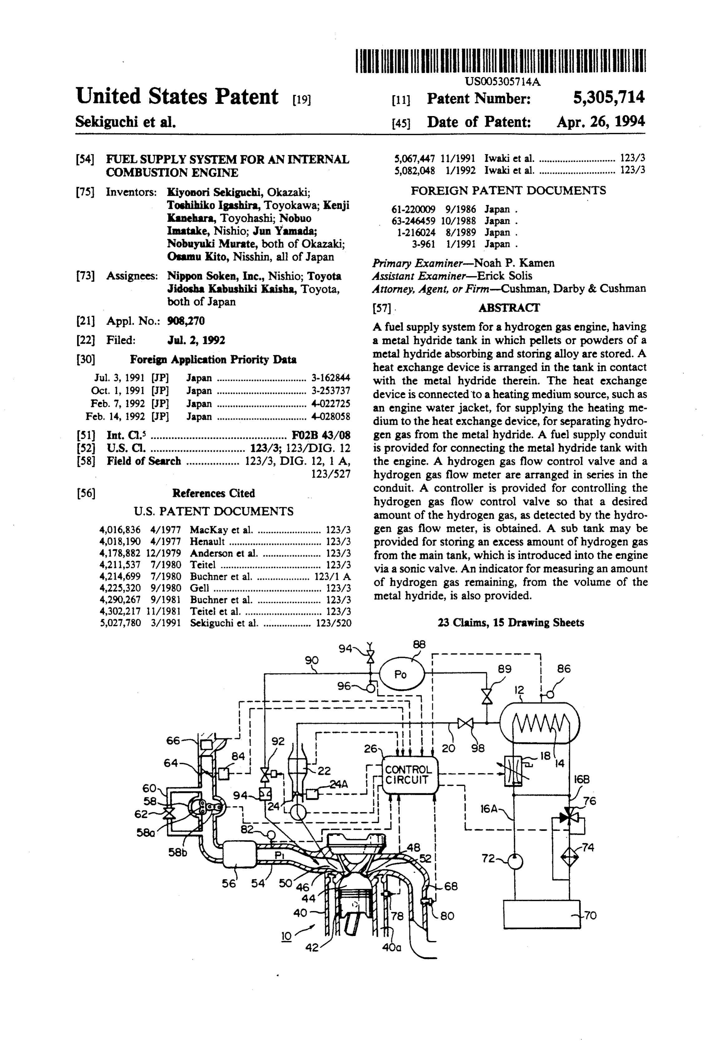
According to the present invention, the amount of invention, reference numeral 10 denotes an internal heating medium fed to the heat exchange device is con combustion engine, such as a spark ignition type engine, trolled so that a desired amount of hydrogen gas is supplied with hydrogen gas as a fuel, and reference generated in the fuel tank, and the amount of hydrogen numeral 12 denotes a metal hydride tank containing gas is controlled such that a desired amount of hydro pellets 13 made of an alloy able to absorb and store gen gas is introduced into the engine. As a result, a hydrogen, such as Ti-Fe. This tank 12 has a relatively pressure regulator for controlling a predetermined pres low inner pressure, and therefore, is advantageous in sure in the fuel supply conduit, enabling a desired that it does not require a high mechanical strength to amount of the hydrogen gas to be introduced into the maintain a sufficient safety, as required by a high pres engine, can be eliminated, and as a result, a required 10 sure cylinder for storing liquid hydrogen. A heat ex amount of hydrogen can be very quickly introduced change device 14 is arranged in the tank 12, for heating into the engine, to thereby increase the speed of the or cooling the metal hydride pellets 13 stored in the response of the engine. tank 12, and is composed of a heat exchange pipe, with BRIEF DESCRIPTION OF THE DRAWINGS fins, in which a recirculating flow of hot water from a 5 water jacket (not shown) of the internal combustion
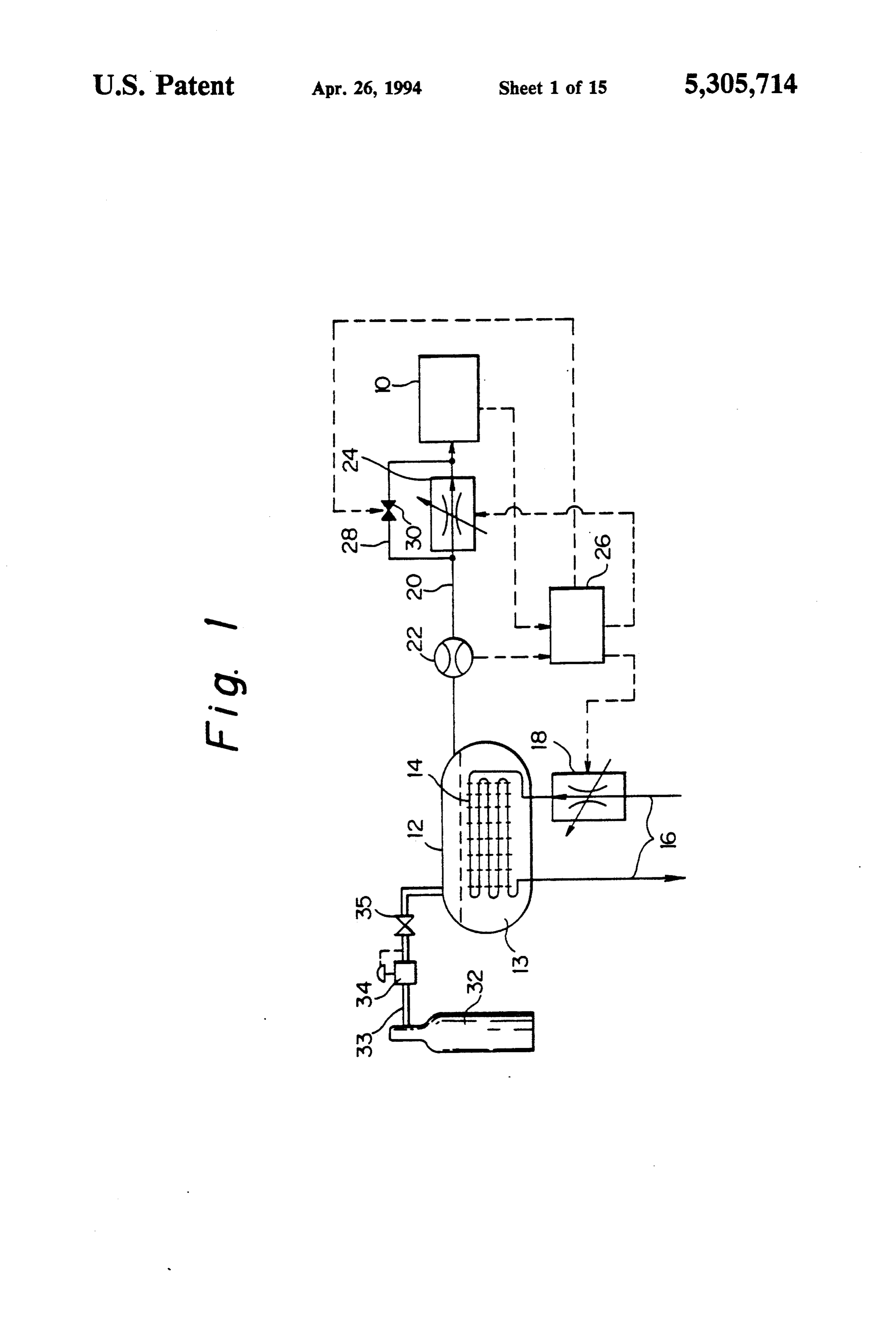
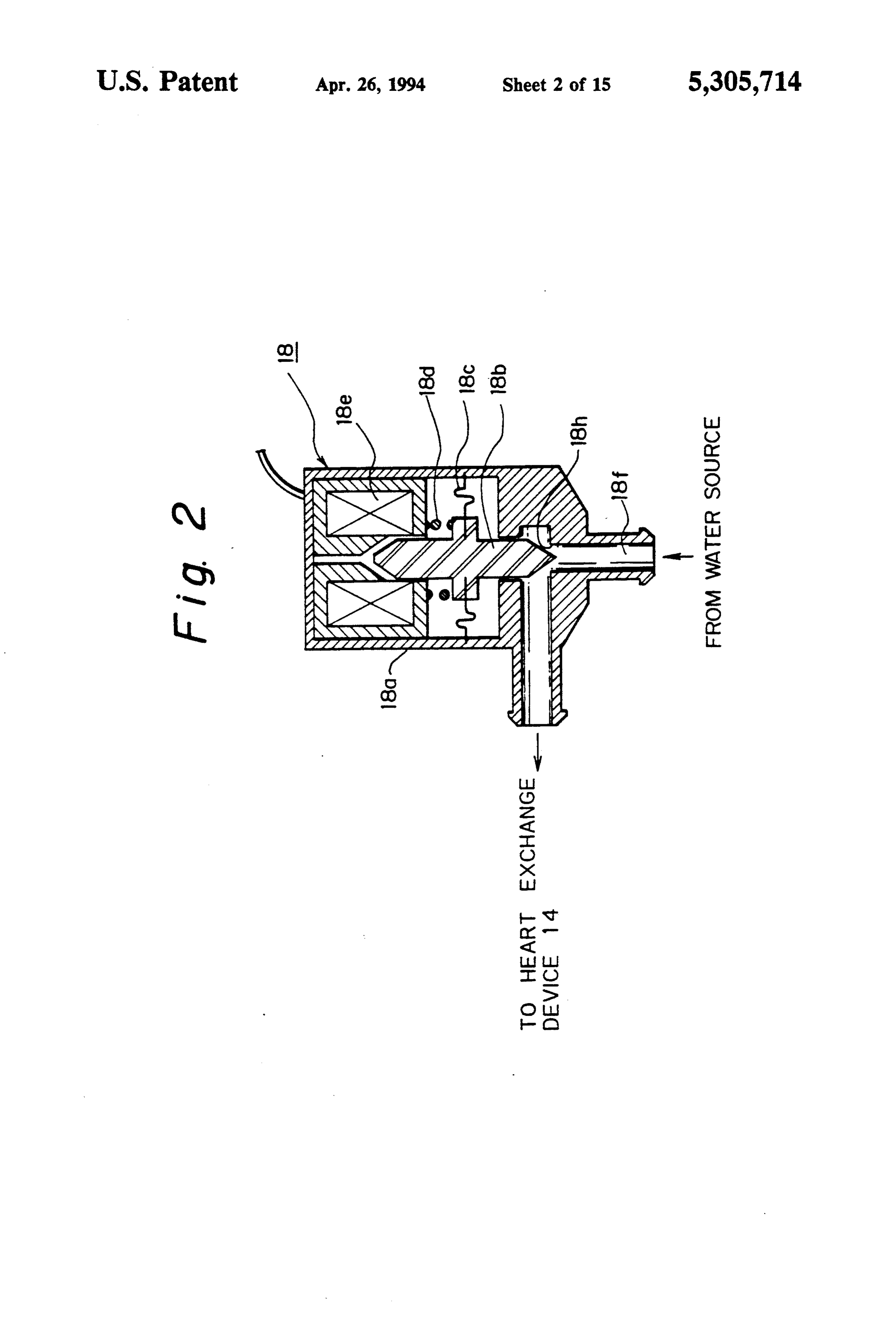
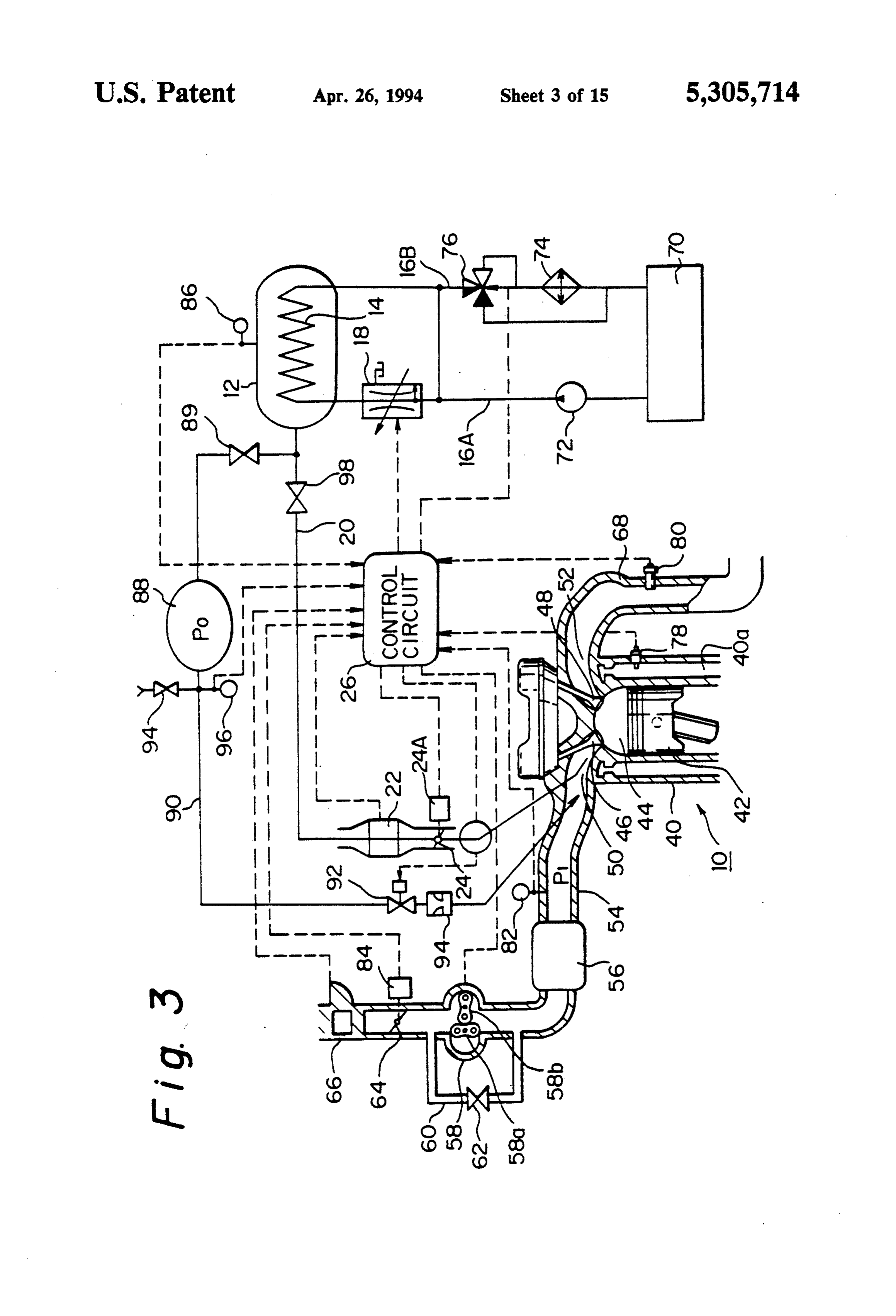
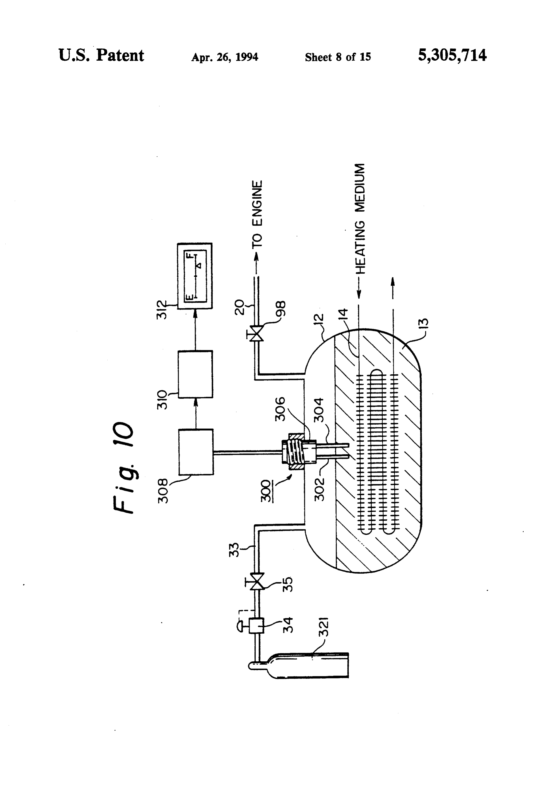
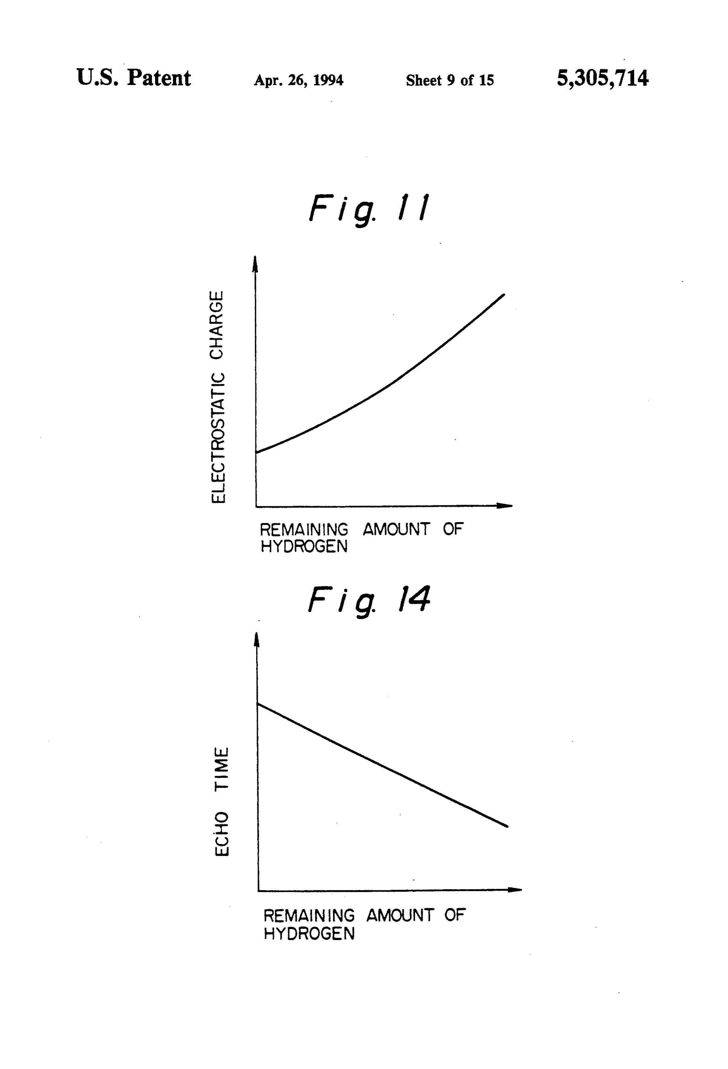
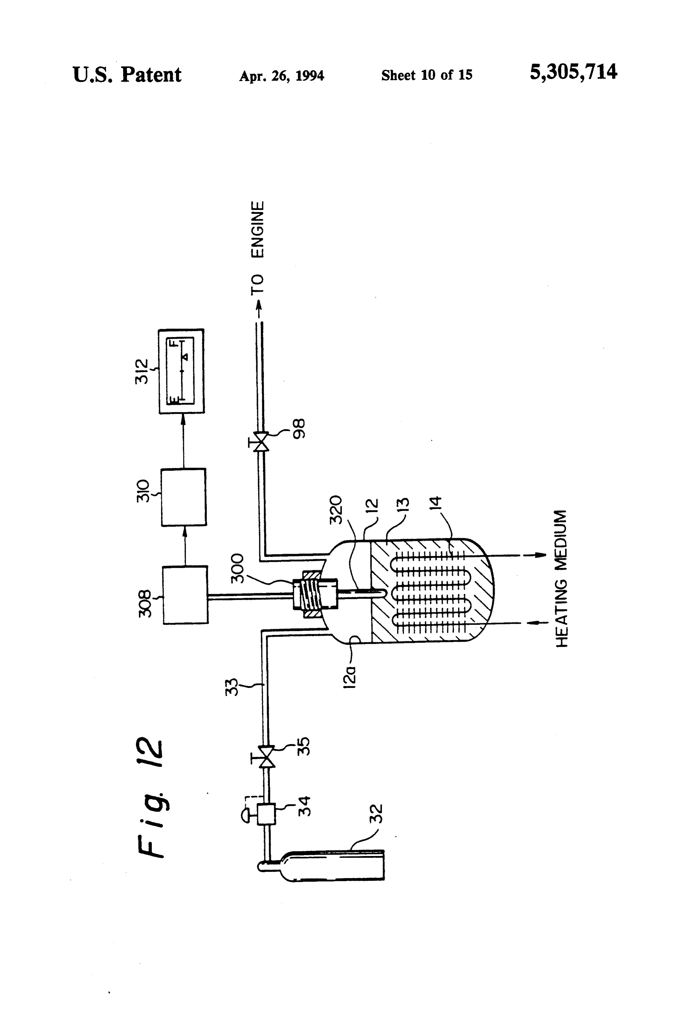
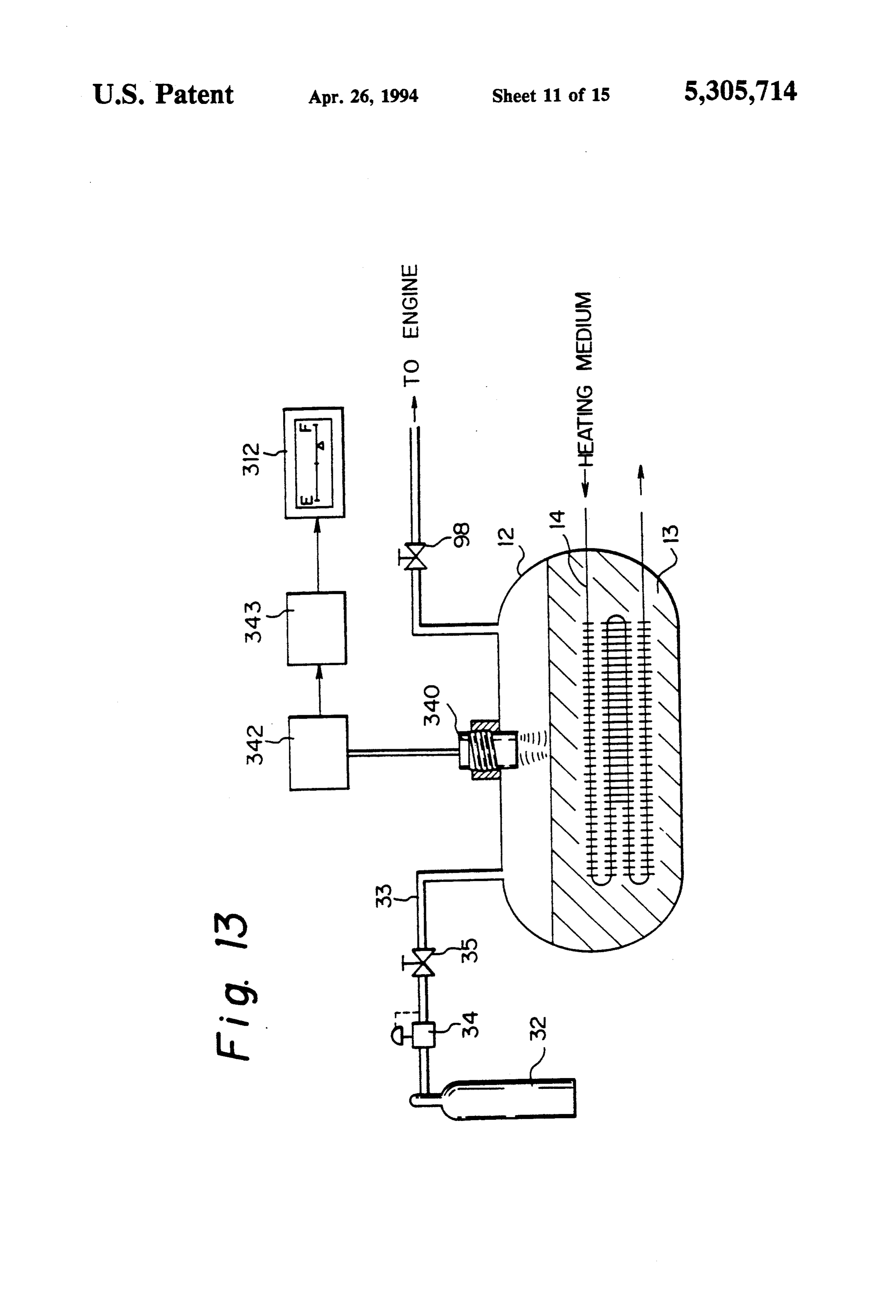
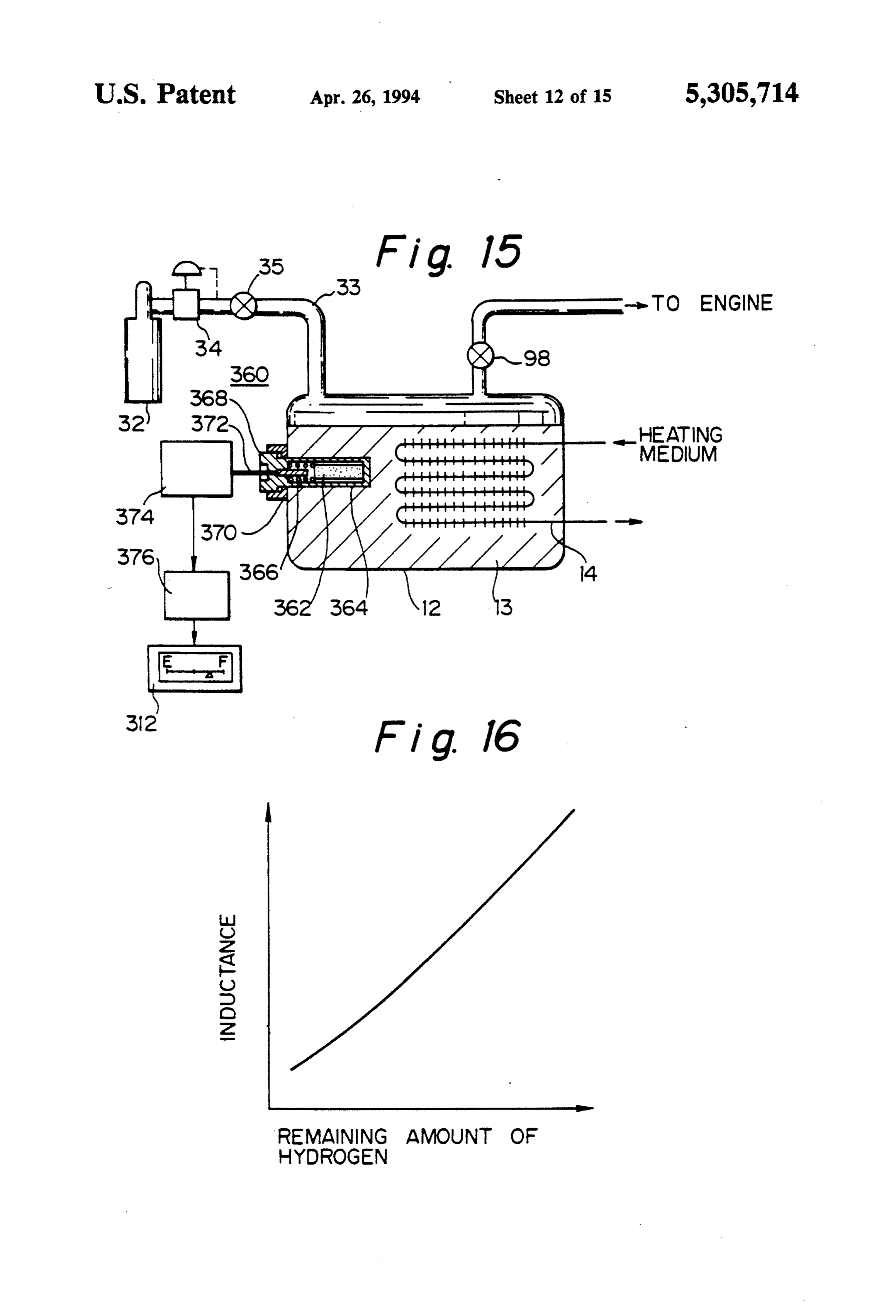
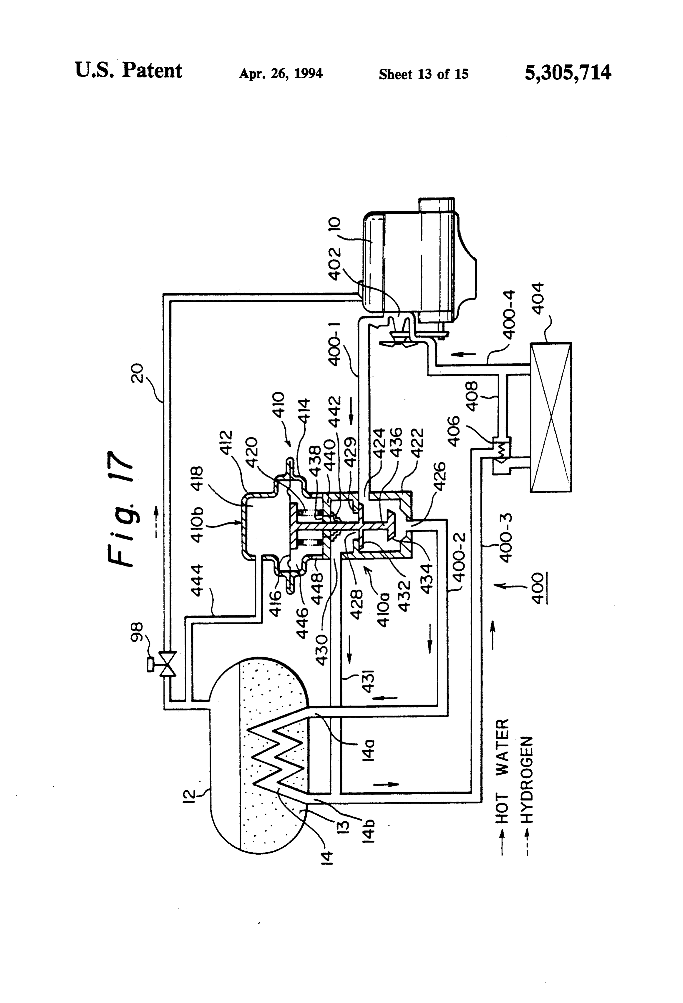
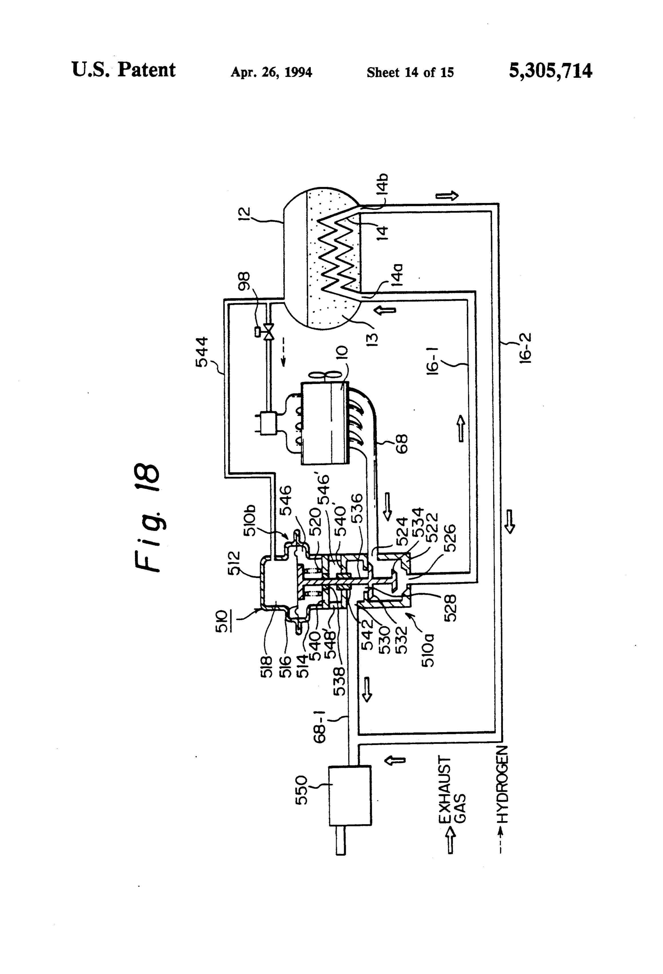
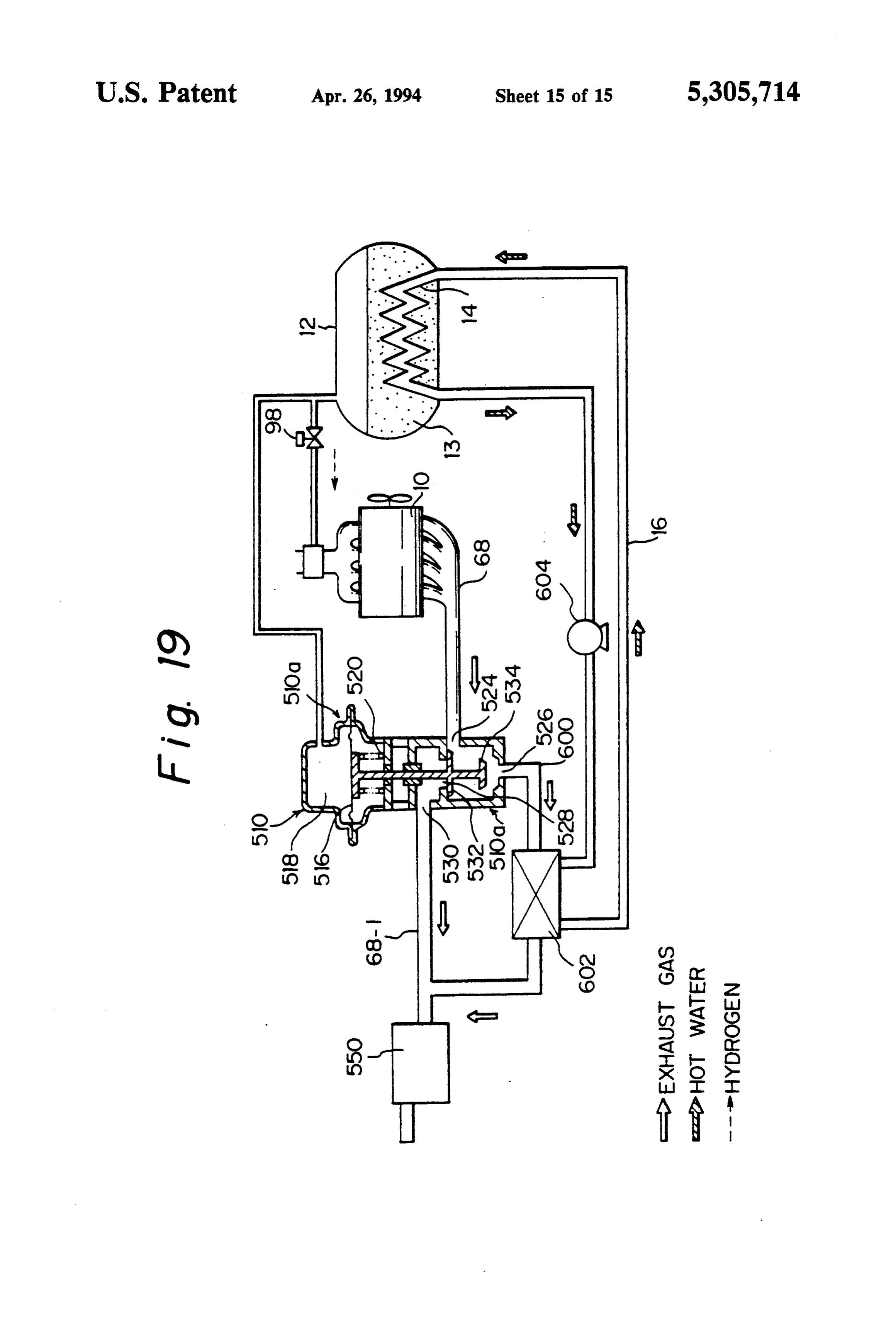
FIG. 1 is a schematic view of a fuel supply system for engine is created.
a hydrogen internal combustion engine according to the Regarding the alloy for creating the metal hydride, present invention; Ni-La alloy or Ti-Mn alloy can be used instead of Ti-Fe FIG. 2 is a cross sectional view of a hot water control alloy. These Ti-Fe, Ni-La, and Ti-Mn alloys are low valve shown in FIG. 1; 20 temperature metal hydrides able to absorb or emit hy FIG. 3 is a schematic view of a fuel supply system as drogen gas at a low temperature in a range of between a second embodiment of the present invention; a normal temperature to about 100' C. Another group FIG. 4 is a cross sectional view of a sonic nozzle of alloys for creating the metal hydride is composed of shown in FIG. 3; high temperature metal hydrides able to absorb and FIG. 5 shows a relationship between the pressure 25 emit hydrogen at a high temperature of between 300 to ratio and the flow amount passing through the sonic 400 C., and includes Mg-Ni and Mg-Mn alloys. Ac nozzle; cording to this embodiment, in which the engine cool FIG. 6 is a flow chart illustrating the operation of the ing water is used as a heating medium, preferably a low embodiment shown in FIG. 3; temperature metal hydride is employed. FIG.7 shows a modification of a heating device for a 30 The heat exchange device 14 is constructed by a sub tank; serpentine pipe arranged in the metal hydride tank 12 FIG. 8 is a cross sectional view tank taken along a such that the pipe is in contact with the metal hydride line XIII-XIII in FIG. 7; pellets 13 stored in the tank 12. The serpentine pipe is FIG. 9 is a flow chart illustrating the heating opera connected to an engine water conduit 16, for heating or tion of the sub tank shown in FIG. 8; 35 cooling the metal hydride pellets 13 stored in the tank FIG. 10 shows another embodiment of the present 12 via the heat exchange device 14. A water flow invention, including a device for detecting an amount of amount control valve 18 (FIG. 2) is mounted in the hot fuel remaining in the tank; water conduit 16, for controlling the amount of heating FIG. 11 shows a relationship between an electrostatic or cooling water passed through the heat exchange charge and the remaining amount of hydrogen gas; 40 device 14, to thereby control the amount of hydrogen FIG. 12 is similar to FIG. 10 but is a modification gas discharged from the metal hydride pellets restored thereof; in the tank 12. The water conduit 16 is connected to an FIG. 13 shows another embodiment of the present engine water conduit in such a manner that a part or all invention, including a device for detecting an amount of of the engine cooling water is made to by-pass a radiator fuel remaining in the tank, by using an ultrasonic wave; 45 (for heating) or an engine cooling water jacket (for FIG. 14 shows a relationship between an echo time cooling) by using a suitable switching valve (not and the remaining amount of hydrogen gas; shown). In a preferred case, aheat energy of the exhaust FIG. 15 shows another embodiment of the present gas is recovered by the cooling water and the heated invention, including a device for detecting an amount of water is used for heating the pellets 13, or the exhaust fuel remaining in the tank, by an inductance; SO gas itself is introduced into the heat exchange device 14 FIG. 16 shows a relationship between an inductance in the metal hydride tank 12, as a heating medium. and the remaining amount of hydrogen gas; A conduit 20 is provided for a connection of the FIG. 17 shows another embodiment wherein a dia metal hydride tank 12 with the internal combustion phragm valve responsive to a pressure in the tank is engine 10, for introducing the hydrogen gas from the used for controlling the pressure in the tank, and an 55 tank 12 to the engine 10. Unlike the prior art, the con engine cooling water is used for heating the metal hy duit 20 does not have with a pressure regulator for dride in the tank; controlling the pressure of the hydrogen in the conduit FIG. 18 is similar to FIG. 17 but differs therefrom in 20 to a predetermined constant value. According to the that an exhaust gas is used for heating the metal hydride present invention, a hydrogen flow meter 22 is arranged in the tank; and, in the hydrogen supply conduit 20, for detecting the F.G. 19 is similar to FIG. 18 but differs therefrom in amount of the hydrogen gas supplied to the engine. Any that the heat of the exhaust gas is used for heating a known type of hydrogen gas flow meter can be em liquid medium that heats the metal hydride in the tank. ployed, but a mass flow type is preferable to a volumet DESCRIPTION OF THE PREFERRED ric flow type, in view of the fact that the hydrogen is EMBODIMENTS highly sensitive to changes of temperature. Instead of a direct detection, the hydrogen gas flow amount may be
In FIG. 1, showing a first embodiment of the present calculated from a detected pressure and temperature of invention and illustrating the basic idea of the present the hydrogen gas.
Page 19
A flow control valve 24 is arranged in the fuel supply stopper valve 35 is closed and the conduit 33 is discon conduit 20, at a position downstream of the hydrogen nected from the tank 12.
flow meter 22, for controlling the amount of hydrogen During the operation of the engine 10, a flow of hot gas introduced into the engine 10. The flow control water from the water jacket or top tank of a radiator of valve 24 can be any type, including a solenoid operated the engine is created in the heat exchange device 14, type valve or pressure (vacuum pressure or positive whereby the hydrogen gas is separated from the hydro pressure) operated type valve, able to respond to a gen absorbing and storing alloy 13 stored in the tank 12. control, electric signal for controlling the amount of The amount of the hydrogen gas obtained depends on hydrogen gas introduced into the engine 10 per unit of the total amount of heat applied from the heat exchange time. Furthermore, a single type of such a flow control 10 device 14, which in turn is controlled by the degree of valve may be used between different cylinders of the opening of the water flow control valve 18. The thus internal combustion engine, i.e., the valve is arranged in generated hydrogen gas is introduced into the engine a portion of the intake conduit of the engine at which via the conduit 20. The amount of hydrogen flowing in intake passageways (not shown in FIG. 1) from the the conduit 20 is detected by the hydrogen gas flow respective cylinders of the engine are combined. Alter 15 meter 22, and is controlled by the hydrogen flow con nately, such flow control valves can be respectively trol valve 24 connected to the control circuit 26, so that arranged in the respective intake passageways to the a desired amount of the gas is introduced into the engine respective cylinders of the internal combustion engine. via a fuel supply means (not shown), such as fuel injec An electric control circuit 26, i.e., a microprocessors, is provided, to which the hydrogen flow meter 22 and 20 tiongine valves. The hydrogen gas introduced into the en 10 is mixed with an intake air, to produce an air sensors (not shown) arranged in the internal combustion hydrogen mixture which is combusted to provide an engine input signals related to the flow amount of the hydrogen gas, and various signals indicating the operat engine Since power.
the hydrogen has a very small density, com ing conditions of the engine. The control circuit 26 pared with gasoline, a volumetric amount of the fuel in stores a program for outputting signals to the water the hydrogen
flow control valve 18 and hydrogen gas flow control gasoline engine.gasAccording engine is much larger than that of a valve 24 in accordance with operating conditions of the sion is made in the hydrogentogas the invention, no provi supply conduit 20 for engine.
A by-pass pipe 28 is connected to the fuel supply any means, such as a pressure regulator, able to provide conduit 20 so that it bypasses the hydrogen flow control 30 aand large flow resistance to the flow of the hydrogen gas, as a result, according to the present invention, only valve 24, and an electromagnetic control valve 30 is a very limited pressure loss is created across the entire mounted in the by-pass pipe 28. The electromagnetic fuel supply system from the tank 12 to the engine 10, valve 30 is connected to the control circuit 26, and is operated only when the precision of the control of the and thus the engine can quickly respond to a very rapid flow amount of the hydrogen gas is lost. Namely, the 35 acceleration or deceleration operation because a desired flow control operation by the hydrogen flow control amount of hydrogen gas is always supplied to the en valve 24 is assisted by the electromagnetic valve 30, to glne.
thus obtain a desired flow precision. Namely, the pressure regulator device mounted in the It should be noted that the water flow control valve hydrogen gas supply conduit 20 in the prior art inevita 18, the hydrogen flow control valve 24, and the bypass bly causes a delayed response to be created in the sys valve 30 can be of any kind of construction, as long as tem, not and thus a necessary amount of hydrogen gas can be quickly supplied to the engine during an acceler they can be electrically operated by the control circuit 26. Namely, these valves may be an analogue type hav ation or deceleration condition. Contrary to this, the ing a degree of opening continuously varied in accor present invention eliminates the pressure regulator in dance with a level of an electric signal applied thereto. 45 the hydrogen gas supply conduit 20, to thus prevent the Alternatively, the valves may be an ON-OFF type hav occurrence of a pressure drop, and thus very quickly ing opened and closed positions, and a duty control supplies a desired amount of hydrogen gas to the engine provided for obtaining a pulse signal applied thereto 10. Furthermore, according to the present invention, a and obtaining a desired degree of opening determined feedback system is provided for controlling the gas by the duty ratio, which is a ratio of a duration of an ON 50 control valve 24 so that a desired amount of the hydro condition with respect to a duration of one cycle of the gen gas as detected by the sensor 22 is obtained, and the pulse signal. hot water amount control valve 18 is controlled for Now, the operation of the embodiment in FIG. 1 will introducing a desired amount of hot water into the heat be explained. In order to charge the tank 12 with hydro exchange device 14 in the tank 12, so that a desired gen gas a high pressure container 32 holding liquid 55 amount of hydrogen gas is generated in the tank 12. As hydrogen is connected to the tank 12 via a hydrogen a result, a desired large amount of hydrogen gas is al charging conduit 33. A pressure regulator 34 for reduc ways quickly supplied to the engine, even if the engine ing the pressure of the hydrogen gas, and a stopper is in a transient state such as an acceleration condition. valve 35 for allowing the introduction of the hydrogen FIG. 2 illustrates an example of an actual construc gas when required, are provided in the conduit 33. As a 60 tion of the water flow control valve 18, which is com result, the hydrogen gas from the container is intro posed of a casing 18a, a valve member 18b made of a duced into the tank 12, while the tank 12 is cooled by magnetic material and arranged in the casing 18a, a the heat exchange device 14 through which a cooling diaphragm 18c for supporting the valve member 18b, a nedium is passed, and accordingly, a large amount of spring 18d urging the valve member 18b toward the hydrogen gas introduced into the tank can be absorbed 65 closed position thereof, and a solenoid 18e for generat by the hydrogen absorbing and storing alloy pellets ing an electromagnetic force for moving the valve stored in the tank 12 in the metal hydride state. After member against the force of the spring 18d. The casing the absorbing and storing process is completed, the 18a has an inlet port 18f connected to a hot water
Page 20
source, and an outlet port 18g connected to the heat structed as a Roots pump having a pair of rotors 58a and exchange device 14. 58b for generating a supercharged flow of intake air. The solenoid 18e is connected to the control circuit The intercooler 56 cools the air from the supercharger 26 (FIG.1), which generates a signal for controlling the 58 to thereby obtain a desired temperature of the intake electric current in the solenoid 18e, and the lift of the air fed to the combustion chamber 44. A by-pass pas valve member 18b from a valve seat 18h is controlled in sageway 60 is connected to the intake conduit for by accordance with the value of the electric current sup passing the supercharger 58, and a by-pass control valve plied. Namely, the amount of hot water introduced into 62 is located in the by-pass passageway 60 for control the heat exchange device 14 is controlled in accordance ling the by-pass operation to thereby a desired pressure with the electric current supplied. O of intake air from the supercharger 58. A throttle valve The amount of hydrogen required by the engine 10 is 64 is connected to an accelerator pedal (not shown) and determined by the engine operating condition, mainly is arranged upstream of the super-charger 58. An air the intake air amount per engine rotation, and therefore, flow meter 66 is arranged upstream of the throttle valve it is sufficient if an amount of hydrogen gas matching 64, for measuring an amount of intake air introduced the engine operating conditions is generated. Thus, 15 into the combustion chamber 44. The exhaust port 52 is during a steady state condition of the engine, the value connected to an exhaust manifold 68, for discharging of the electric current, which determines the tempera the exhaust gas.
ture of the metal hydride, i.e., the amount of hydrogen Similar to the first embodiment, the heat exchange gas generated, is basically controlled in accordance device 14 formed as a serpentine pipe is arranged in the with the engine operating condition. Contrary to this, 20 metal hydride tank 12 in which fine pellets or powders during a transient state of the engine, the control of the of a hydrogen absorbing and storing alloy are stored. amount of the hot water passed through the valve 18 The heat exchange device 14, is in contact with the differs from that made in the steady state condition. pellets in the tank 12, and is connected to a source 70 of Namely, during the acceleration, the amount of hot hot engine cooling water, such as an water jacket 4.0a in water is increased to be more than in the steady state 25 the engine body 40, via a hot water supply conduit 16A, condition, to thus obtain an increased amount of hydro which connects the hot water source 70 to the heat gen gas. Contrary to this, during a deceleration, the exchange device 14, for introducing the hot water into amount of hot water is reduced compared to that in the the heat exchange device 14, and via a hot water return steady state condition, to thus reduce the amount of conduit 16B, which connects the heat exchange device hydrogen gas obtained. Such a transient state can be 30 14 with the hot water source 70, for returning the hot detected from a rate of change in the degree of depres water to the source 70. A water pump 72 is arranged in sion of the acceleration pedal, or a rate of change in the the hot water supply conduit 16A, to provide a flow of amount of hydrogen sensed by the gas flow meter 22. In hot water. A filter 74 is arranged in the hot water return place of the electric current control of the solenoid, a conduit 16B, in which a three way switching valve 76 is ratio of the duration of an ON time to the duration of 35 also arranged for switching a return flow between a one cycle of the pulse signal, i.e., a duty ratio, can be position at which the hot water passes the filter 74 and used for obtaining a continuously varied degree of a position at which the hot water by-passes the filter 74. opening of the valve 18. The hot water flow control valve 18 is arranged in the As described above, in the first embodiment shown in hot water supply passageway 16A at a position between FIGS. 1 and 2, no provision is made of a regulator for the water pump 72 and the heat exchange device 14, for obtaining a predetermined pressure of the hydrogen at measuring the amount of hot water introduced into the the tank 12, and therefore, a water amount control heat exchange device 14.
valve 18 is controlled in response to the amount of the Similar to the first embodiment, a supply conduit 20, hydrogen gas required. Such a control may cause fluc not. having a pressure regulator, is provided with a tuations in the value of the pressure of the hydrogen gas 45 hydrogen flow meter 22 and a hydrogen flow control at the tank 12, but is considered advantageous in that it valve 24. The fuel supply conduit 20 is connected to the increases the speed of the response of the system shown intake system via a fuel injection valve (not shown) for in FIGS. 1 and 2. injecting hydrogen gas into the intake port 50 of the FIG. 3 shows a second embodiment basically em engine 10. In this embodiment, the flow control valve ploying the concept of the present invention shown in 50 24 is a butterfly type connected to an actuator 24A FIG. 1 but modified for actual application to a super thereof.
charged fuel injection type internal combustion engine. An electronic control circuit 26 as a microprocessor The components corresponding to those shown in FIG. is also provided, to which the hydrogen flow meter 22 1 are given the same reference numbers. The internal and the air flow meter 66, and other sensors, input sig combustion engine 10 is a spark ignition type supplied 55 nals related to the flow amount of the hydrogen gas, with a hydrogen gas as a fuel. The engine 11 has an and various signal indicating the operating conditions of engine body 40 having cylinders (only one is shown in the engine. These sensors are a temperature sensor 78 FIG. 3), each containing a piston 42 above which a mounted on the engine body 40 for detecting a tempera combustion chamber 44 is formed. An intake valve 46 ture of the engine cooling water, an O2 sensor 80 and an exhaust valve 48 are provided for each cylinder. mounted on the exhaust manifold 68 for detecting an When the intake valve 46 is opened a combustible mix oxygen density in the exhaust gas, a pressure sensor 82 ture from an intake port 50 is introduced into the com mounted on the intake manifold 54 for detecting an bustion chamber 44, and a resultant combustion gas is intake air pressure, and a throttle sensor 84 for detecting exhausted to an exhaust port 52 when the exhaust valve a degree of opening of the throttle valve 64. The control 48 is opened. The intake port 50 is connected to an 65 circuit 26 is connected to the hot water flow control intake manifold 54 connected, via an intercooler 56, to valve 18 and the actuator 24A of the hydrogen gas flow a supercharger 58 connected to a crankshaft (not control valve 24 and has a stored program for executing shown). The supercharger 58 is, for example, con the control supply of the amount of hot water to the
Page 21
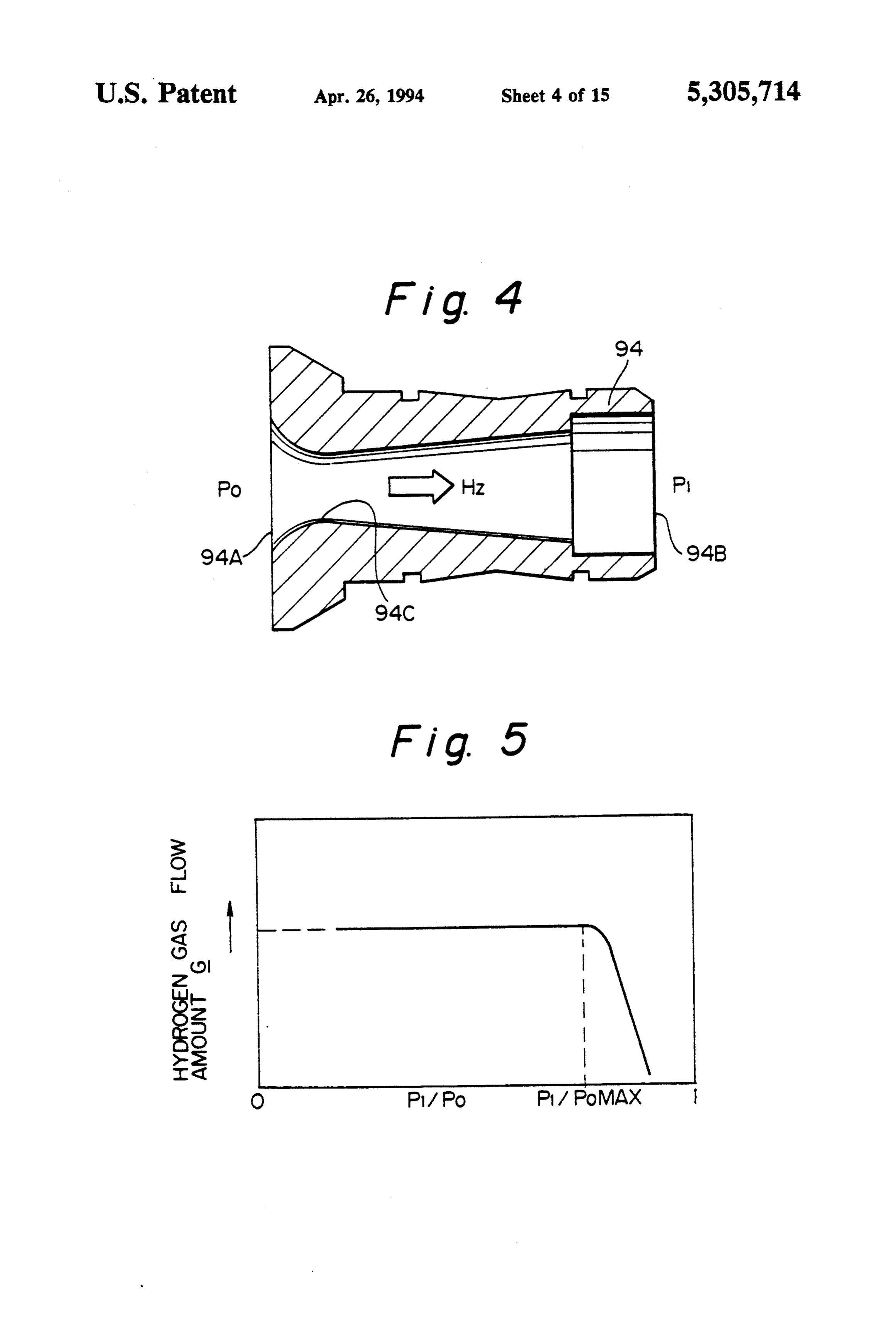
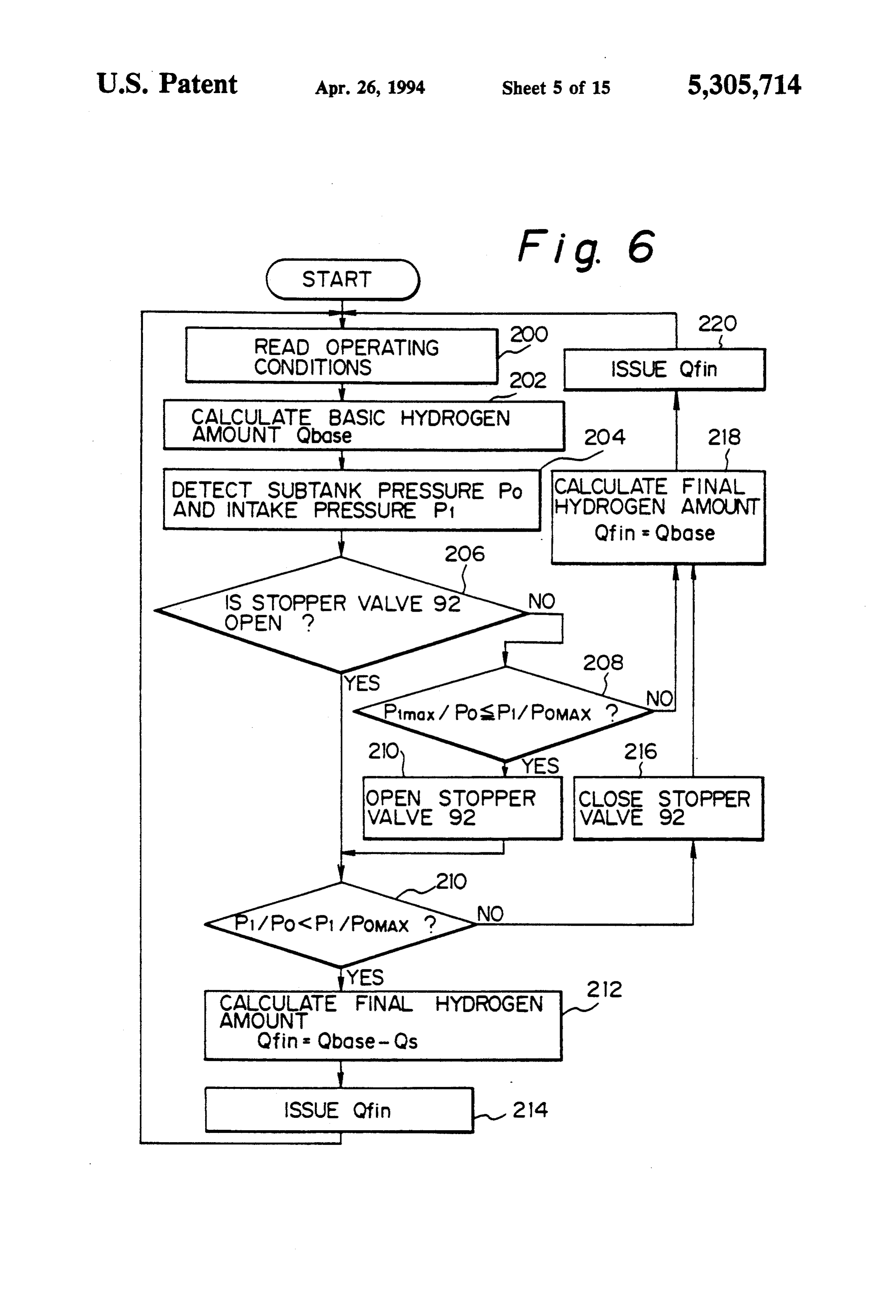
heat exchange device 14 and the amount of hydrogen therethrough, and defining an inlet 94A and an outlet gas introduced into the engine 10. 94B. The inlet 94A is axially inwardly tapered toward a In this second embodiment, unlike the first embodi portion 94C having the smallest inner diameter, and the ment in FIGS. 1 and 2, provision is made for a control inner diameter of the axial opening then gradually wid of the pressure in the tank 12 by a sensor 86 for detect ened toward the outlet end 94B. As easily seen from ing a pressure of the hydrogen gas in the tank, and the FIG. 4, a constant amount of air flow is obtained re control circuit 26 operates, in response to the detected gardless of the value of the ratio P1/Po, when the value pressure, to control the water flow control valve 18 so of the ratio is in a range (sonic area) wherein it is smaller that the hydrogen pressure inside the tank 12 is main than the maximum value (P1/Po)x. As well known, tained at a desired value. This means that greater the O in such an area, the speed of the air flow corresponds to amount of hydrogen gas consumed by the engine 10, the the sonic speed. The dimension of the sonic nozzle 94 is greater the amount of hot water introduced into the such that an amount of hydrogen gas introduced into heat exchange device 14. the intake manifold 54 is smaller than a predetermined When the vehicle moves from a high load operating amount, which is smaller than the amount of hydrogen condition wherein a large amount of hydrogen gas is 15 gas necessary for carrying out an idling operation. Such consumed to a stopped (dead soak) condition wherein a setting of the amount of the hydrogen gas via the sonic the consumption of hydrogen gas is sharply reduced, nozzle 94 makes it possible to use the sonic supply of the the separation of the hydrogen gas from the metal hy hydrogen gas throughout the whole engine operating dride continues for a while due to heat generated by the area. Namely, the stopper valve 92 is opened when it is hot water remaining in the tank 12, and the heat pre determined that the ratio of the pressure in the intake served by the tank 12 and the hydrogen absorbing-stor manifold sensed by the sensor 82 to the pressure sensed ing alloy itself, causing the pressure of the hydrogen to by the pressure sensor 96 is smaller than the predeter exceed the control pressure. To combat this problem, a mined value (P/Po)MAY, so that the hydrogen gas can second (sub) tank 88 is located in a second fuel supply pass through the sonic nozzle 94. conduit 90, and one end thereof is connected to the first 25 FIG. 6 is a flowchart illustrating a control of the fuel conduit 20 upstream of the hydrogen flow meter amount of hydrogen gas flow in the second embodiment 22, and the other end is connected to the intake line in FIG. 3. After the initialization of the routine at step adjacent to the intake port 50. A relief valve 89 is ar 200, various operating conditional signals are read from ranged in the second fuel conduit 90 upstream of the various sensors, such as the throttle sensor 84 and the second tank 88, and a stopper valve 92 and a sonic 30 intake pressure sensor 82, etc., and at step 202, a basic nozzle 94 are arranged in the second fuel conduit 90 hydrogen gas amount Qass is calculated based on the downstream of the second tank 88. Furthermore, a detected operating conditions. The basic hydrogen gas safety valve 94 is arranged in a conduit connected at amount QBASE is the amount of hydrogen gas required one end to the second conduit 90 at a position adjacent for obtaining a desired engine performance under the to and downstream of the second tank 88, and having a 35 detected operating conditions. At step 204, a pressure second end opened to the atmosphere. A hydrogen Po at the sub-tank 88 sensed by the sensor 96 is read out, pressure sensor 96 is also provided and is connected to and at step 206, it is determined if the stopper valve 92 the control circuit 26. Note, a fuel cut valve 98 is ar is closed. When it is determined that the stopper valve ranged in the first fuel conduit 22 downstream of the 92 is closed, the routine goes to step 208 and it is deter point of which the second fuel conduit 90 is connected mined if the ratio of the maximum possible value of the to the first conduit 20. intake pressure Pinax to the pressure of the sub-tank Po As well known to those skilled in this art, the sonic is smaller than the maximum ratio (P/Po)Maxin FIG. 5. nozzle 94 can emit a flow at a constant speed (sonic When it is determined that PMAX/Po) (P/Po)MAY, the speed) when a pressure difference across the sonic noz routine goes to step 210 and the stopper valve 92 is zle 94 is smaller than a predetermined value. A constant 45 opened, and then the routine goes to step 211, and it is pressure is detected from the pressure values detected determined if the ratio of the actual value of the intake by the sensor 82 for detecting the intake pressure in the pressure P1 to the pressure of the sub-tank Pois smaller intake manifold 54 and the sensor 96 for detecting the than the maximum ratio (P1/Po)MAYin FIG. 5. When it pressure at the outlet of the tank 88 (inlet to the sonic is determined that P/Po C(P1/Po)MX, this means that nozzle 94), and the stop valve 92, which is usually 50 ratio P1/Pois in a range at which a sonic effect is pro closed, is opened when the pressure ratio is lower than vided to cause a flow of the hydrogen at a sonic speed a predetermined value, whereby hydrogen gas in the as illustrated with reference to FIG. 5, the open state of second tank 88 is introduced into the intake manifold 54 the stopper valve 92 obtained at the step 210 is main of the internal combustion engine. Note, upon such an tained, and the routine then goes to step 212, where a introduction of hydrogen gas from the sub-tank 88 to 55 final amount of hydrogen gas flow Qin is calculated as the intake manifold 54, a correction of a degree of open the basic hydrogen flow amount Qase minus the hydro ing of the hydrogen gas flow control valve 24 is carried gen gas flow amount Qs at the sonic nozzle 94. At step out, to thus reduce the amount of hydrogen gas intro 214, a signal is output to the actuator 24A of the hydro duced into the engine via the main hydrogen gas con gen flow control valve 24 so that the calculated final duit 20, so that the total gas amount supplied is un hydrogen flow amount Qin as the basic amount Qase changed. minus the amount Q is injected into the intake port 50 Details of the construction of the sonic nozzle 94 will via the injector (not shown).
be explained with reference to FIGS. 3 and 4. FIG. 3 When it is determined at step 210 that P/Po shows a basic construction of the sonic nozzle, and 2(P/Po)Max, this means that ratio P/Pois in a range FIG. 4 shows a relationship between the pressure ratio at which the sonic effect cannot be provided (FIG. 5), of the output pressure P1 to the inlet pressure Po, and a and therefore, the routine goes to step 216 and the stop hydrogen gas flow amount G passing through the sonic per valve 92 is closed, and to step 218, where a final nozzle 94. The sonic nozzle 94 has an axial opening amount of hydrogen gas flow Qin is calculated as the
Page 22
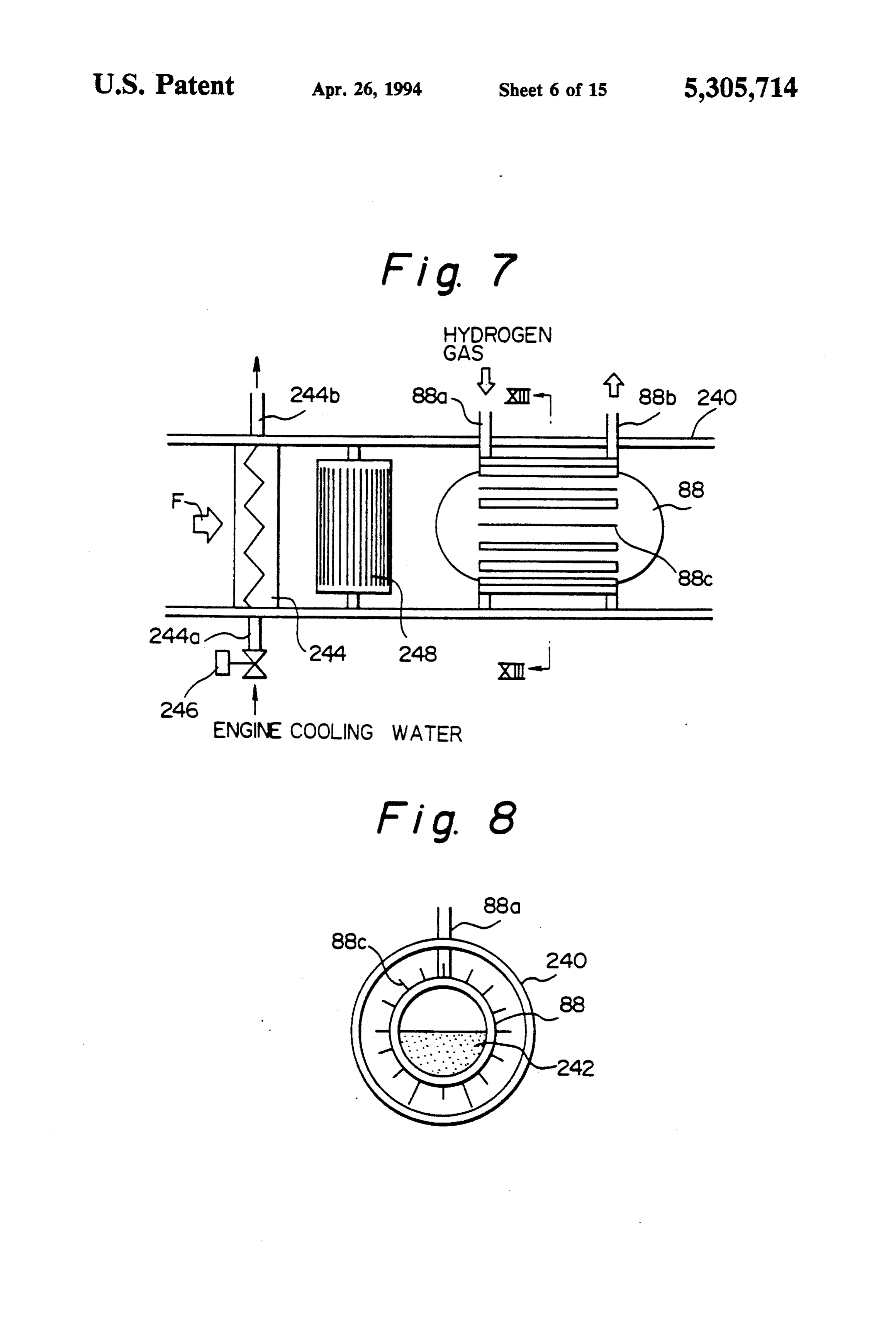
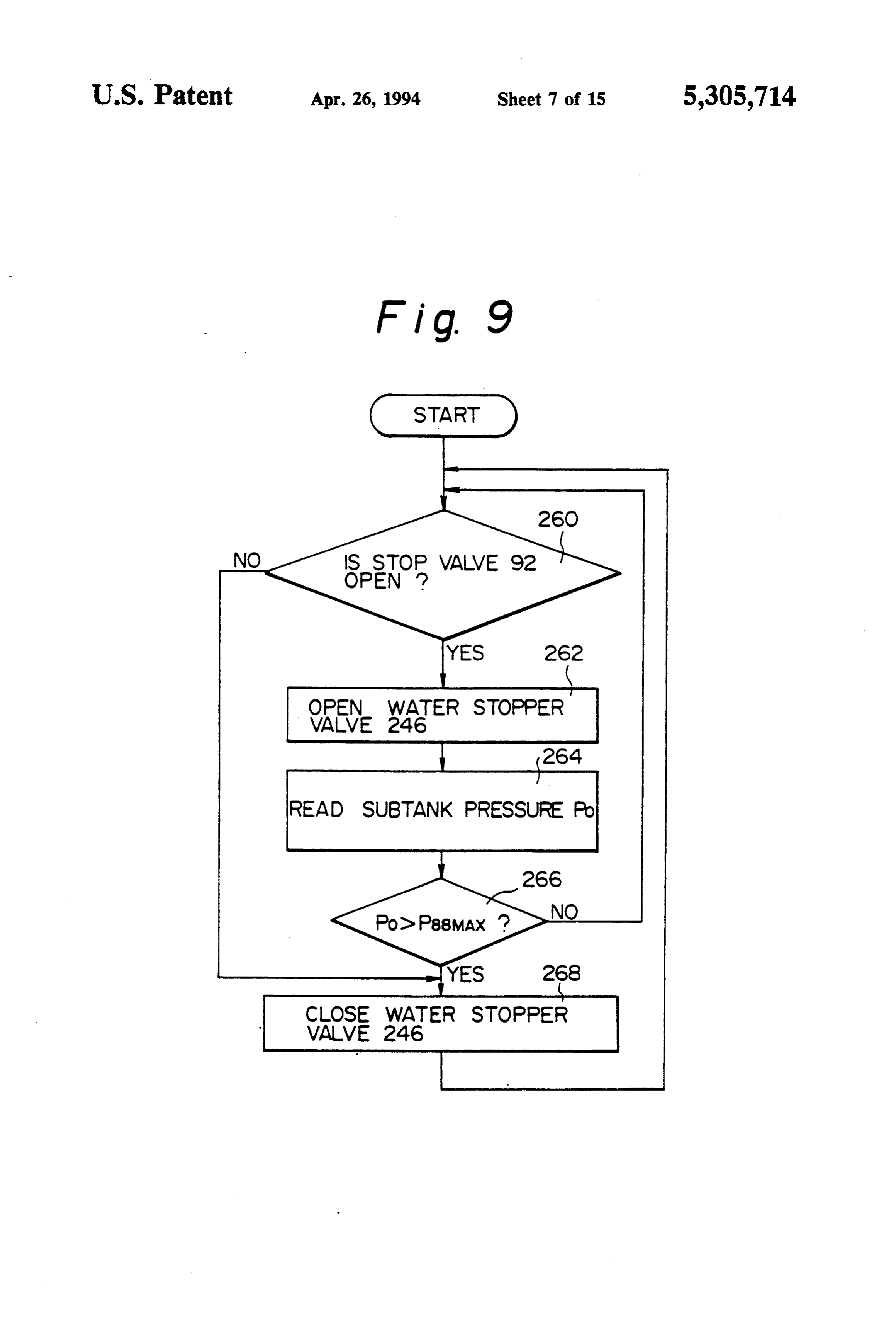
basic hydrogen flow amount Qbase itself. At step 220, a thus the blower 248 generates a flow high temperature signal is output to the actuator 24A of the hydrogen air in contact with the sub tank 88, to thereby heat the flow control valve 24 so that the calculated final hydro sub tank 88, and as a result, the metal hydride pellets 242 gen flow amount Qin as the basic amount Qbass, itself is stored in the tank 33 generate hydrogen gas. At step injected into the intake port 50 via the injector (not 264, a pressure Poof the hydrogen gas in the sub tank 88 shown). is detected by the pressure sensor 96 in FIG. 3, and at When it is determined at step 208 that the ratio of the step 266 it is determined whether the detected value of maximum possible value of the intake pressure Pimax to the pressure Pois larger than a predetermined pressure the pressure of the sub-tank Po is not smaller than the P88Max. When it is determined that Po)P88MAX, the maximum ratio (P/Po)Marin FIG. 5, this means that it 10 routine goes to step 268 and the stopper valve 246 is is theoretically impossible to obtain the sonic effect, and closed, whereby the introduction of hot water into the thus the routine goes to steps 218 and 220 and the basic heater core 244 is stopped, and accordingly, the temper amount Qbase is injected while the stopper valve 92 is ature of the air in contact with the sub tank 88 is low closed. ered to thus cause a separation of the hydrogen gas from As mentioned above, the second embodiment ensures 15 the metal hydride pellets, resulting in a reduction in the that the sonic effect via the sonic nozzle 94 is always pressure of the hydrogen gas in the sub tank 88. When obtained when introducing the hydrogen gas from the it is determined at step 266 that Pos P88MAX, as a result second tank 88 into the intake manifold 54 via the sec of the reduction of the hydrogen gas pressure, step 268 ond hydrogen gas conduit 90, whereby excess hydro is by-passed and the stopping valve 246 is opened to gen stored in the second tank 88 is effectively utilized. 20 allow an introduction of hot water into the heater core The removal of the hydrogen gas from the second tank 244.
88, however, can cause a drop in the temperature of the When it is determined at step 260 that the stop valve metal hydride in the tank 88 due to the heat absorbing 92 is closed, i.e., the sonic introduction operation is not reaction occurring in the tank 88 when the hydrogen carried out, and the routine goes directly to step 268 to gas is removed therefrom. Such a fall in the temperature 25 close the hot water stopper valve 246 and prevent an inside the tank 88 causes the pressure therein to be also introduction of hot water into the heater core 244. As a reduced, and thus the reduced pressure drops out of the result, the temperature of the air in contact with the sub sonic area before the hydrogen in the second tank 88 is tank 88 is lowered, and thus the pressure of the hydro fully removed. Apart from this problem, when the hy gen gas therein is also lowered, and as a result, a greater drogen gas is taken out from the second tank 88, another 30 absorption of the hydrogen gas to the metal hydride 242 problem arises when the excess hydrogen gas is intro in the sub tank 88 occurs.
duced into the sub tank 88 from the main tank 12. Namely, in the embodiment of FIG. 7, the sub tank 88 Namely, the introduction of the excess hydrogen from is heated by the hot air flow when the hydrogen is taken the main tank 12 to the sub tank 88 causes a heat gener out from the sub tank 88, so that as much as possible of ating reaction in the sub tank 88, because the hydrogen 35 the hydrogen in the sub tank 88 is consumed, and the gas is absorbed by the metal hydride stored in the sub sub tank 88 is cooled by the cooled air flow for absorb tank 88, causing the temperature of the metal hydride to ing as much as possible of the hydrogen gas from the be increased, and accordingly, pressure inside the tank main tank 12, when the hydrogen is not taken out from 88 to be raised above the permissible level. FIGS. 7 and the sub tank 88. As a result, a storage of excess hydro 8 show a variation of a construction of a second tank by gen from the main tank 12 and a desired consumption of which this difficulty is overcome. hydrogen gas are effectively attained. Furthermore, this In FIG. 7, the sub tank 88 is arranged in a heater duct embodiment makes it possible to obtain an increased 240 in which an air flow is created. The sub tank 88 is maximum amount generated hydrogen gas, to thus in provided with an inlet 88a for receiving hydrogen gas crease the output power of the hydrogen gas engine. from the main tank 12, and an outlet 88b for the hydro 45 Also, the excess amount of hydrogen gas generated in gen gas to be introduced into the intake system of the the metal hydride tank cannot leak to the atmosphere, engine 10 under the sonic effect, as explained above. and thus this system is much safer than a conventional The sub tank 88 is provided with outer wall heat ex system. Furthermore, this embodiment allows an effec change fins 88c in contact with the airflow in the heater tive use of excess air, causing the distance covered to be duct 240. Note, the sub rank 88 contains pellets of a 50 increased. The employment of the sonic nozzle 94 hydrogen absorbing-storing alloy 242, as shown in FIG. makes it easy to precisely measure the flow amount, and 8. In FIG. 7, a heater core 244 is arranged in the heater simplifies the measurement construction. duct 240. This heater core 244 has an inlet 244a and an The principle shown in the embodiments in FIGS. 3 outlet 244b for the engine cooling water, and stopper and 7 can be applied to a usual gasoline engine if it has valve 246 provided at the inlet 244a to the heater core 55 construction corresponding to the embodiments in 244. In the heater duct 240, a blower 248 is arranged FIGS. 3 and 7. Namely, the first tank 12 will be a usual between the heater core 244 and the sub tank 88 for tank used in the construction of an internal combustion generating a forced flow of the air from the outside of engine fuel system, and the second chamber 88 will be a the vehicle, as shown by an arrow F. charcoal canister usually used for storing gasoline FIG. 9 is a flowchart illustrating the operation of the 60 vapor from the gasoline tank. After a condition is ob system shown in FIG. 7. At step 260 it is determined tained for purging the gasoline held by the charcoal whether the first stopper valve 92 in the sonic supply canister, the sonic nozzle 94 is operated to allow the line 90 is open. When it is determined that the stopper charcoal canister to separate the required amount of valve 92 is open, i.e., an introduction of hydrogen gas gasoline, which is then introduced into the engine. An under the sonic effect is being carried out, the routine 65 amount of gasoline introduced into the engine by a fuel goes to step 262 and the water supply stopper valve 246 injection valve will be reduced by the amount of the is opened whereby the hot, engine cooling water from gasoline introduced into the engine via the sonic nozzle the engine 10 is introduced into the heater core 244, and 94.
Page 23
In the embodiment in FIG. 10, an electrostatic sensor the amount of hydrogen gas remaining in the tank 12 to 300 for detecting an amount of hydrogen remaining in be precisely detected regardless of any change in the the metal hydride tank 12 is provided, in which the size of the pellets after prolonged use, due to deteriora metal hydride 13 as fine pellets or powder is stored so tion.
that it occupies about 80 percent of the total space of the The metal hydride powders 13 sometimes have a tank 12. The heat exchange device 14, through which a property such that they are easily attached to the sur high temperature engine cooling water is passed, is faces of the electrodes 302 and 304. In this case, a small located in the body of the metal hydride 13. The hydro amount of the powders remains attached to the elec gen gas conduit 20 is connected at one end to the tank trode 302 and 304, regardless of any lowering in the 12 and is connected at the other end to the intake mani 10 level of the metal hydride powders 13, which adversely fold to the internal combustion engine 10. The electro affects a precise detection of the value by the electro static sensor 300 is located at the top wall of the tank 12, static charge. To combat to this problem, the noncon and has a pair of electrodes 302 and 304 extending verti ductive coating on the electrodes 302 and 304 may be a cally downward so that tip ends of the electrodes 302 material having a low friction coefficient, such as a and 304 are penetrated into the body of the metal hy 15 fluorine-based resin.
dride powder 13 for at least 10 percent of their length, An error in a measurement of the electrostatic charge even when no hydrogen is charged. Since the metal may occur because, during the charging or removing of hydride 13 has an electric conductivity, the electrodes the hydrogen gas, the metal hydride powder 13 is scat 302 and 304 are provided with anon conductive coating tered in the space in the tank. To prevent this, a silicone on the entire outer surface thereof. The sensor 300 is oil can be impregnated in the metal hydride powders, to further provided with a holder 306 for the electrodes avoid such a scattering.
302 and 304; the holder 306 being sealingly connected FIG. 12 shows a modification of the embodiment of to the top wall of the tank 12 by a screw member or a the sensor for detecting an amount of hydrogen remain flange member. The electrodes 302 and 304 are con ing in the tank 12. Instead of detecting an electrostatic nected to a circuit 308 for detecting an electrostatic 25 change in the electrostatic change between the elec charge, which is connected to a circuit 310 for convert trodes 302 and 304 in the embodiment in FIG. 10, a ing the electrostatic charge detected by the circuit 308 change in the electrostatic charge between a single to an amount of hydrogen gas remaining in the tank 12, electrode 320 and a wall 12a is detected, which has a and to a indicator 312 mounted on a dashboard for coating made from an electric insulating material on the indicating the amount of remaining hydrogen calcu 30 inner surface thereof in contact with the metal hydride lated by the circuit 310. powders, which has, per se an electric conductivity. As explained with reference to FIG. 1, during the This arrangement makes it possible to detect a change in charging of the tank 12 before the vehicle is run, the the electrostatic charge between the electrode 320 and hydrogen gas from the high pressure container 32 is the wall 12a of the tank 12, which is caused by a change introduced into the tank 12 while the pellets in the tank 35 in the amount of hydrogen gas absorbed by the hydro are cooled by the heat exchange device 14, to thereby gen absorbing-storing alloy.
cause the alloy pellets to absorb the hydrogen gas and FIG. 13 shows another embodiment for measuring become a metal hydride. This absorption of the hydro the amount of hydrogen gas remaining in the tank 12. In gen gas causes the volume of the pellets 13 to be ex place of a detection of the change in the electrostatic panded and, accordingly, a rise in the upper level of the volume, an ultrasonic sensor 340 is provided for detect pellets. Such an expansion in the volume of the pellets ing the level of the metal hydride powders in the tank 13 in the tank 12 causes an increase in the electrostatic 12. The sensor 340 includes an emitter (not shown) of an charge detected by the pair of electrodes, and such a ultrasonic wave toward the top level of the metal hy change in the electrostatic charge is detected by the dride powder 13 in the tank 12, and receiver (not circuit 308 and is converted into an amount of hydrogen 45 shown) of the ultrasonic wave reflected by the top level gas remaining in the tank 12, by the circuit 310, based on of the metal hydride 13. A circuit 342 is provided for the relationship shown in FIG. 11. The indicator 312 calculating the duration (echo time) from the emitting visually shows the calculated amount of hydrogen re of the ultrasonic wave to the receiving of the reflected maining in the tank 12. ultrasonic wave. A circuit 343 is also provided for cal During the running of the vehicle, the hydrogen gas SO culating an amount of hydrogen remaining from a rela generated by the pellets in the tank 12, by a heating of tionship between the echo time and the hydrogen re the tank 12, is consumed by the engine 10. The more maining amount, as shown in FIG. 14. The calculated hydrogen gas consumed, the greater the reduction in remaining hydrogen amount is indicated at the indicator the volume of the pellets in the tank 12, whereby the 312. According to this embodiment in FIG. 13, the upper level of the pellets 13 in the tank 12 is lowered, 55 ultrasonic sensor 340 is a noncontact type, and there and thus an amount of the electrostatic charge between fore, an advantage is obtained in that an attachment of the pair of the electrodes is reduced. This reduction in the metal hydride powders thereto does not occur, the amount of hydrogen remaining in the tank 12 is which may otherwise generate an error in measure indicated by the indicator 312. ment. Another advantage is that an expansion of the The size of the pellets 13 also is meritably reduced by metal hydride in the tank 12 will not cause damage to deterioration after prolonged use, and thus the volume the sensor due to a mechanical contact pressure applied thereof in the tank 12 may vary. To compensate for thereto by the metal hydride in the tank. such a reduction in the size of the pellets after pro FIG. 15 shows another embodiment of the sensor for longed use, each time the tank 12 undergoes a periodical measuring the amount of hydrogen gas remaining in the maintenance, the pellets 13 are completely deaerated, 65 tank, by a change in the electric inductance. A sensor and the circuit 310 may function such that the detected 360 includes a rod-shaped block 362 made of the same value of the instant electrostatic charge is used as an powder material as that of the metal hydride 13 in the updated zero value of the hydrogen amount, allowing tank 12, by shaping same in a mould under pressure.
Page 24
The rod-shaped block 362 is fitted into a casing 364 According to the embodiment of FIG. 17, a flow having a closed bottom end, and a coil spring 366 is control valve 410 is provided, which is constructed by provided so that the block 362 is urged into contact a flow control part 410a for controlling the amount of with the closed bottom of the casing 364. The portion of the engine cooling water in the line 400 and an actuator the casing 364 with which the block 362 is in contact at s part 410b for operating the flow control section 410a in the cylindrical thereof is a perforated material made, for accordance with the pressure of the hydrogen in the example, by sintering a stainless steel material to pro tank 12. The actuator part 410b has a top diaphragm vide a porous filter construction through which the cover 412, a bottom diaphragm cover 414, a diaphragm hydrogen gas in the metal hydride 13 in the tank 12 can 416 fixed between the covers 412 and 414, a pressure be freely introduced into the block 362 made of the O chamber 418 inside the top cover 412 above the dia same material (hydrogen absorbing and storing mate phragm 416, and a spring 420 urging the diaphragm 416 rial) as the metal hydride 13. The outer end of the casing upward. The flow control section 410a has a casing 422 364 has a cap portion 368 inserted to a socket portion defining an inlet port 424 connected to the section 400-1 370 fixed to the outer wall of the tank 12, and a detect of the line 400, for an introduction of the water from the ing member 372 is inserted into the cap portion 368 so 15 engine 10, an outlet port 426 connected to the section that a free end thereof provided with a detecting coil 400-2 of the line 400 for a removal of the water toward faces the block 362 with a space therebetween. Note, the heat exchange device 14, valve ports 428 formed on seal members are arranged between the cap portion 368 a partition wall 429 of the casing, and by-pass port 430 and the socket 370, and between the cap portion 368 and connected to the section 400-3 of the line 400 via a the rod-shaped detecting member 372, to obtain a gas 20 by-pass conduit 431, a valve 432 for controlling the port tight connection. A detecting circuit 374 is provided for 428, a valve 434 for controlling the port 426, and a valve . generating a high frequency voltage applied to the coil stem 436 to which the valves 432 and 434 are fixedly portion in the rod member 370 facing the block 362, and connected. The valve stem 436 extends upward, and a distance between the rod 370 and the block 362 is thus is slidable with respect to a valve guide 438 in a changed in accordance with the amount of the hydro 25 separating wall portion 440, and is connected to the gen gas in the tank 12, because the volume of the block diaphragm 416 so that the valve members 432 and 434 362 is changed in accordance with the volume of the are moved together with the movement of the dia metal hydride 13 in the tank, which corresponds to the phragm 416. A rubber boot 442 is provided for sealing amount of hydrogen in the tank12. Such a change in the off engine cooling water running toward the valve distance between the rod member 370 and the block 362 30 guide 438. The pressure chamber 418 above the dia causes the inductance of the coil in the rod member 372 phragm 416 is connected, via a line 444, to a space to be varied, which is changed into a direct current at above the level of the metal hydride 13 in the tank 12, the detecting circuit 374. A calculating circuit 376 cal and a chamber 446 which is connected to the atmo culates an amount of hydrogen gas remaining in the sphere via an opening 448, is formed below the dia tank from the detected inductance, based on a relation 35 phragm 416.
ship as shown in FIG. 16 between the value of the in The operation of the hydrogen engine causes the ductance and the amount of remaining hydrogen gas. temperature of the cooling water in the cooling water The calculated amount of remaining hydrogen gas is line 400 to be higher than a predetermined value, e.g., indicated by the indicator 312. 80' C., which causes the thermostat 406 to be switched The embodiments directed to the sensors shown in to a position at which the engine cooling water is intro FIGS. 8 to 13 allow a detection of a hydrogen remain duced into the radiator 404, to thereby lower the tem ing amount of between 0% to 100%, in real time, and perature of the engine cooling water. When the temper therefore, such a sensor, when used in relation to the ature is thus lowered below the predetermined value, tank as a fuel gauge, can always monitor the remaining the thermostat 406 is switched to a position at which the amount of fuel, and thus prevent a running out of the 45 engine cooling water flows in the by-pass passageway fuel. 408, while by-passing the radiator 404, and as a result, FIG. 17 shows another embodiment wherein a pres the temperature of the engine cooling water is main sure sensitive valve is used for controlling the introduc tained at a substantially constant temperature of 80 C. tion of hot water into the heat exchange device in the The consumption of the hydrogen gas in the metal metal hydride tank, for controlling the generation of 50 hydride tank 12 causes the pressure therein to fall below hydrogen gas therefrom. In this embodiment, the inter a predetermined pressure, and accordingly, the spring nal combustion engine is provided with a engine cool 420 causes the diaphragm 416 to be displaced upward, ing system having a recirculation line 400 constructed so that the first valve 432 closes the valve port 428 and by sections 400-1, 400-2, 400-3 and 400-4, a water pump the second valve 434 opens the outlet port 426. As a 402 located in the line 400 for ensuring a recirculation of 55 result, the engine cooling water introduced into the the cooling water in the line 400, a radiator 404 located valve 410 from the section 400-1 via the inlet port 424 between the sections 400-3 and 400-4 of the line 400 for flows into the section 400-2 via the outlet port 426. The obtaining a heat exchange of the cooling water with the cooling water is then introduced into the heat exchange outside air flow, and a thermostat 406 that is opened to device 14 in the tank 12, and returned to the engine via obtain a flow of the cooling water through a by-pass the section 400-3, the radiator 404 or by-pass pipe 408, line 408 by-passing the radiator 404, when the tempera and the section 400-4. The passage of the engine cooling ture of the cooling water is higher than a predetermined water at substantially 80 C. is sufficient to heat the low value. The heat exchange device 14 in the metal hydride temperature type metal hydride 13 stored in the tank 12, tank 12, and in contacting with the metal hydride 13 in to thus generate hydrogen gas from the metal hydride the tank 12, is connected, at one end 14a to the section 65 tank 12, and as a result of this generation of hydrogen 400-2 of the engine water recirculation line 400, and at gas, the pressure inside the tank 12 is increased. The the other end 14b is connected to the section 400-3 of increase in the pressure inside tank 12 to a predeter the engine water recirculation line 400. mined pressure causes the diaphragm 416 to be dis
Page 25
placed downward against the force of the spring 420, exhaust gas to the inlet 14a of the heat exchange device and thus the first valve 432 opens the valve port 428 and 14, valve ports 528, and a second outlet port 530, which the second valve 434 closes the outlet port 426. As a are connected to an exhaust pipe 68-1, a valve 532 for result, the engine cooling water introduced into the controlling the port 528, a valve 534 for controlling the valve 410 from the section 400-1 via the inlet port 424 port 526, and a valve stem 536 to which the valves 532 flows into the by-pass line 431 via the ports 428 and 430, and 534 are fixedly connected. The valve stem 536 and accordingly, the engine cooling water by-passes the extends upward so that the valve stem 536 is slidable heat exchange device 14 in the tank 12 and is returned to with respect to a valve guide 538 in a separating wall the engine via the section 400-3, the radiator 404 or portion S40, and is connected to the diaphragm 516 so by-pass pipe 408, and the section 400-4. The by-passing 10 that the valve members 532 and 534 are moved together of the engine cooling water causes the temperature of with the movement of the diaphragm 516. In place of the metal hydride 13 in the tank 12 to fall, and thus the the rubber boot 442 in FIG. 17, a seal member 542 generation of hydrogen gas from the metal hydride tank having a sleeve shape is arranged on a partition wall 12 is suppressed, and as a result, the pressure inside the 540', and a space 546 open to the atmosphere is created tank 12 is lowered. 15 between the partition walls 540 and 540', in addition to Namely, a pressure of hydrogen gas in the metal a chamber 546 formed below the diaphragm 516, which hydride tank 12 higher than a predetermined value chamber 546 is connected to the atmosphere via an causes the valve 410 to be closed to thereby stop the opening 548". A pressure chamber 518 is connected, via introduction of the engine cooling water to the heat a line 544, to the space above the level of the metal exchange device 14, and a pressure of hydrogen gas in 20 hydride in the tank 12. Connected to the exhaust pipe the metal hydride tank 12 lower than the predetermined 68-1 from the valve 510 at position upstream of a muf value causes the valve 410 to be opened to allow the fler 550 is a pipe 16-2 from the outlet 14b of the heat introduction of the engine cooling water to the heat exchange device 14.
exchange device 14. As a result, the control of the en A reduction of a hydrogen pressure in the metal hy gine cooling water by the valve 410 maintains a prede 25 dride tank 12 due to a consumption thereof causes the termined pressure in the tank 12. pressure in the chamber 518 to fall below a predeter An advantage of this embodiment of FIG. 17 is that mined pressure, and thus the spring 520 causes the dia the construction for obtaining the predetermined pres phragm 516 to be displaced upward so that the first sure inside the tank 12 consists of only mechanical parts, valve 532 closes the valve port 528 and the second valve and the electrically operated solenoid valve 18 as in the 30 534 opens the outlet port 526. As a result, an exhaust gas embodiment in FIGS. 1 and 3 and a relay(s) for operat from the exhaust manifold 68 is directed to the pipe 16-1 ing the valve can be eliminated, which may otherwise via the port 524 and 526, and is introduced into the heat generate electrical sparks which may accidentally ignite exchange device 14 via the pipe 16-1. After a heat ex gas leaked from the tank or the gas supply line. Further change operation at the device 14 for heating the metal more, an advantage of a very simple construction for hydride 13 in the tank 12, the exhaust gas is directed to controlling the metal hydride tank pressure can be ob the muffler 550 via the pipe 16-2. The passage of the tained. exhaust gas in the heat exchange device 14 can heat the FIG. 18 is another embodiment obtaining a purely high temperature type metal hydride 13 stored in the mechanical type construction for controlling the pres tank 12 to thus generate hydrogen gas in the metal sure in the tank. In this embodiment, in place of the heat hydride tank 12, and as a result of this generation of from the engine cooling water a heat emitted from the hydrogen gas, the pressure inside the tank 12 is in exhaust gas of the engine 10 is used as the medium for creased. The increase in the pressure inside the tank 12 heating the metal hydride 13 in the tank 12 by the heat to a predetermined pressure causes the diaphragm 516 exchange device 14. Namely, the low temperature type to be displaced downward against the force of the metal hydride employed in the embodiment in FIG. 17 45 spring 520, so that the first valve 532 open the valve can be made to generate enough heat for separating the port 528 and the second valve 534 closes the outlet port hydrogen gas by using the engine cooling water at a 526. As a result, the exhaust gas from the exhaust pipe temperature as low as 80 C., but, the low temperature 68 is directed to the pipe 68-1 via the ports 528 and 530, of the engine cooling water is not sufficient to obtain a and accordingly, the flow of exhaust gas by-passes the desired amount of hydrogen from the high temperature 50 heat exchange device 14 in the tank 12. The by-passing type metal hydride. The embodiment in FIG. 18 is di of the exhaust gas causes the temperature of the metal rected to the use of such a high temperature type metal hydride 13 in the tank 12 to fall to thus cause the genera hydride. Here, a valve 510 is arranged in the exhaust tion of hydrogen gas from the metal hydride tank 12 to pipe 68 of the engine for controlling the flow of the be suppressed, and as a result, the pressure inside the exhaust gas. The valve 510 is constructed by a flow 55 tank 12 is lowered.
control part 510a for controlling the flow amount of the Namely, a pressure of hydrogen gas in the metal exhaust gas, and an actuator part 510b for operating the hydride tank 12 higher than a predetermined value flow control section 510a in accordance with the pres causes the valve 510 to be closed to thus stop the intro sure of hydrogen in the tank 12. The actuator part 510b duction of the exhaust gas to the heat exchange device has a top diaphragm cover 512, a bottom diaphragm 14, and a pressure of hydrogen gas in the metal hydride cover 514, a diaphragm 516 fixed between the covers tank 12 lower than the predetermined value causes the 512 and 514, a pressure chamber 518 inside the top valve 510 to be opened to allow the introduction of the cover 512 above the diaphragm 516, and a spring 520 exhaust gas to the heat exchange device 14. As a result, urging the diaphragm 516 upward. The flow control the control of the flow of the exhaust gas by the valve section 510a has a casing 522 defining an inlet port 524 65 510 always maintains a predetermined pressure in the connected to the exhaust manifold 68 for an introduc tank 12.
tion of the exhaust gas from the engine 10, a first outlet Note, in the embodiment of FIG. 18, a chamber 546" port 526 connected to a pipe 16-1 for introducing the is provided between the partitions 540 and 504", and is
Page 26
open to the atmosphere so that an air flow can freely diaphragm 416 or 516 can be directly connected to the pass through the chamber 546". As a result, damage to wall of the tank 12, to thus control the flow of heating the diaphragm 516 by the high temperature of the ex medium (engine cooling water or exhaust gas) in accor haust gas passing through the flow control portion 510b dance with a difference between the force caused by the is prevented. pressure of the hydrogen gas and the force of the spring FIG. 19 shows another embodiment wherein the low 420 or 520. Furthermore, in place of the diaphragm 416 temperature type metal hydride 13 is used, and the heat or 516, another type of pressure receiving member such is obtained from the exhaust gas. The control valve 510 as a piston can be used.
is substantially the same as that used in FIG. 18, and We claim:
therefore, a detailed explanation thereof is omitted. In O 1. A fuel supply system for an internal combustion place of directing the exhaust gas to the heat exchange engine, wherein a hydrogen gas is used as the fuel, the device 14, a passageway 600 is provided for connecting system comprising:
the first outlet port 526 of the valve 510 with the ex a fuel tank in which a metal hydride is stored; haust pipe 68-1, and a heat exchange device 602 is ar a heat exchange device arranged in the fuel tank for ranged in the passageway 600 for obtaining a heat ex 15 controlling a temperature of the metal hydride in change operation between the exhaust gas passing the tank;
through the passageway 600 and a heating liquid, such first control means for controlling an amount of heat as water, passing through the passageway 16 to the heat ing medium introduced into the heat exchange exchange device 14. A recirculation pump 604 is situ device so that a desired amount of hydrogen gas is ated in the passageway 16 for ensuring the recirculation 20 generated from the metal hydride in the tank; of the flow of heating liquid in the passageway 16. a fuel supply conduit connecting the fuel tank with A reduction of hydrogen pressure in the metal hy the internal combustion engine for introducing the dride tank 12 due to a consumption thereof causes the hydrogen gas into the engine; and pressure in the chamber 518 to fall below a predeter second control means for controlling an amount of mined pressure, and thus the spring 520 causes the dia 25 hydrogen gas flowing in the fuel supply conduit so phragm 516 to be displaced upward so that the first that a desired amount of hydrogen gas is intro valve 532 closes the valve port 528 and the second valve duced into the engine in accordance with an oper 534 opens the outlet port 526. As a result, an exhaust gas ating condition of the engine, wherein the second from the exhaust manifold 68 is directed to the pipe 68-1 control means comprises:
via the port 524 and 526, which is introduced into the 30 sensor means for detecting an amount of hydrogen heat exchange passageway 600 and then enter the ex gas in the fuel supply conduit, and haust pipe 68-1. The passage of the high temperature of means for controlling the amount of hydrogen gas the exhaust gas via the heat exchange device 602 raises introduced to the engine so that a desired amount the temperature of the heating liquid recirculated in the of the hydrogen gas detected by the sensor means is passageway 16 and the increase in the temperature of 35 introduced into the engine. the heat exchange medium in the passageway 16 causes 2. A fuel supply system according to claim 1, wherein arise in the temperature of the low temperature type the first control means comprise means for detecting a metal hydride 13 stored in the tank 12, to thereby gener pressure of the hydrogen gas in the tank, and valve ate hydrogen gas in the metal hydride tank 12. As a means for controlling an amount of the heating medium result of the generation of the hydrogen gas, the pres introduced into the heat exchange means so that a de sure inside the tank 12 is increased, and an increase in sired amount of the heating medium is introduced into the pressure inside the tank 12 to a predetermined pres the heat exchange means for obtaining a predetermined sure causes the diaphragm 516 to be displaced down pressure of the hydrogen inside the tank. ward against the force of the spring 520, whereby the 3. A fuel supply system for an internal combustion first valve 532 opens the valve port 528, and the second 45 engine, wherein a hydrogen gas is used as the fuel, the valve 534 closes the outlet port 526. As a result, the system comprising:
exhaust gas from the exhaust pipe 68 is directed to the a fuel tank in which a metal hydride is stored; pipe 68-1 via the ports 528 and 530, and accordingly, the a heat exchange device arranged in the fuel tank for exhaust gas by-passes the heat exchange device 602 in controlling a temperature of the metal hydride in the passageway 600. The by-passing of the engine cool 50 the tank;
ing water causes a drop in the temperature of the heat first control means for controlling an amount heating exchanging liquid in the passageway 16, and thus the medium introduced into the heat exchange device temperature of the metal hydride 13 in the tank 12 is so that a desired amount of hydrogen gas is gener reduced, whereby the generation of hydrogen gas from ated from the metal hydride in the tank, wherein the metal hydride tank 12 is suppressed, and as a result, 55 the first control means comprises: the pressure inside the tank 12 is lowered. sensor means for detecting an amount of the hydro According to this embodiment in FIG. 18, high tem gen gas introduced into the engine, and perature exhaust gas is used for a heat exchange with valve means for controlling an amount of the heat water used for heating the low temperature type metal ing medium introduced into the heat exchange hydride 13, for controlling the pressure in the tank 12. means in accordance with a detected amount of In the embodiments of FIGS. 16 to 18, the flow con the hydrogen introduced into the engine so that trol valve 410 or 510 is moved between a position at a desired amount of the heating medium is intro which one valve is open and the other valve is closed, duced into the heat exchange means; and a position at which one valve is closed and the other a fuel supply conduit connecting the fuel tank with valve is opened. Nevertheless, to increase the linearity 65 the internal combustion engine for introducing the of the control of the amount of heating medium, the hydrogen gas into the engine; and valve 410 or 510 can be moved to an intermediate posi second control means for controlling an amount of tion between the above two extreme positions. Also, the hydrogen gas flowing in the fuel supply conduit so
Page 27
that a desired amount of hydrogen gas is intro sonic effect is obtained and closing the stopper valve duced into the engine in accordance with an oper when the sonic effect is not obtained. ating condition of the engine. 8. A fuel supply system according to claim 7, wherein 4. A fuel supply system according to claim 3, wherein the stopping control means comprises means for detect the valve means comprises a valve member for control ing a pressure at the second fuel supply conduit at a ling an amount of the heating medium introduced into position upstream of the sonic nozzle, and means for the heat exchange device, and a solenoid means for closing the stopper valve when the detected pressure in obtaining a desired degree of opening of the valve mem relation to an intake pressure is larger than a predeter ber in accordance with an amount of hydrogen gas mined highest limit.
introduced into the engine. O 9. A fuel supply system according to claim 6, further 5. A fuel supply system for an internal combustion comprising a heating means for heating the second fuel engine, wherein a hydrogen gas is used as the fuel, the tank so that a desired temperature of the metal hydride system comprising: in the second tank is maintained. a fuel tank in which a metal hydride is stored; 10. A fuel supply system according to claim 9, a heat exchange device arranged in the fuel tank for 15 wherein said heating means comprise a duct in which an controlling a temperature of the metal hydride in outside air flows; the second tank being arranged in the the tank; duct and in contact with the air flow, and a heater first control means for controlling an amount of heat means arranged in the duct at a position upstream of the ing medium introduced into the heat exchange tank, for heating the air flow directed to the second tank.
device so that a desired amount of hydrogen gas is 11. A fuel supply system according to claim 10, generated from the metal hydride in the tank; wherein the heater means comprise a heater core a fuel supply conduit connecting the fuel tank with through which an engine cooling water from the engine the internal combustion engine for introducing the is passed, a stopper valve for controlling an introduc hydrogen gas into the engine, wherein no provision 5 tion of the water to the heater core, a sensor for measur is made for a pressure regulator in the fuel supply ing a pressure in the second tank, and means for control conduit for obtaining a predetermined amount of ling the stopper means to thereby control the introduc the hydrogen; and second control means for controlling an amount of tion of the water to the heater core and obtain a prede hydrogen gas flowing in the fuel supply conduit so 30 termined pressure inside the second tank. that a desired amount of hydrogen gas is intro engine, wheresupply
system for an internal combustion hydrogen gas is used as the fuel, the duced into the engine in accordance with an oper system comprising:
ating condition of the engine. a fuel tank in which a metal hydride is stored; 6. A fuel supply system for an internal combustion a heat exchange device arranged in the fuel tank for engine, wherein a hydrogen gas is used as the fuel, the 35 controlling the temperature of the metal hydride in system comprising: the tank;
a first fuel tank in which a metal hydride is stored; first control means for controlling the amount of a heat exchange device arranged in the fuel tank for heating medium introduced into the heat exchange controlling a temperature of the metal hydride in device so that a desired amount of the hydrogen the tank; 40 gas is generated from the metal hydride in the tank; first control means for controlling an amount of heat a fuel supply conduit for connecting the fuel tank ing medium introduced into the heat exchange with the internal combustion engine for introduc device so that a desired amount of hydrogen gas is ing the hydrogen gas into the engine; generated from the metal hydride in the tank; second control means for controlling a hydrogen gas a first fuel supply conduit connecting the first fuel 45 flow amount in said fuel supply conduit so that a tank with the internal combustion engine for intro desired amount of the hydrogen gas is introduced ducing the hydrogen gas into the engine; into the engine in accordance with an operating a second fuel tank in which a metal hydride is stored; condition of the engine; an auxiliary fuel supply conduit for connecting the means for measuring a change in the volume of the first fuel supply conduit with the second tank; metal hydride stored in the tank, and; means arranged in the auxiliary fuel supply conduit means for calculating, from the detected change in for passing hydrogen gas from the first tank to the the volume of the metal hydride, the amount of second tank when a pressure in the first tank ex hydrogen gas remaining in the fuel tank. ceeds a predetermined value; 13. A fuel supply system according to claim 12, a second fuel supply conduit for connecting the sec 55 wherein the means for measuring the volume change ond tank with the engine, providing a supplemen comprise a pair of spaced apart electrodes in contact tary supply of fuel into the engine; and with the metal hydride stored in the tank, the electrodes second control means for controlling a hydrogen gas having nonconductive coatings on the surfaces in flow amount through the first fuel supply conduit contact with the metal hydride, and means for detecting so that the amount of hydrogen gas passed through an electrostatic charge between the electrodes as indica the first fuel supply conduit is compensated by an tive of the amount of hydrogen remaining. amount of hydrogen gas passed through the second 14. A fuel supply system according to claim 13, fuel supply conduit. wherein one of the pair of electrode is a wall of the tank. 7. A fuel supply system according to claim 6, further 15. A fuel supply system according to claim 13, comprising a sonic nozzle arranged in the second fuel 65 wherein the nonconductive material has a low coeffici supply conduit, a stopper valve arrange in series to the ent of friction.
sonic nozzle in the second fuel conduit, and stopping 16. A fuel supply system according to claim 15, control means for opening the stopper valve when the wherein the material is a fluoride based resin.
Page 28
17. A fuel supply system according to claim 12, value the cooling water is introduced into the heat ex wherein the metal hydride in the tank is impregnated by change device in the tank and when the pressure of the a silicone oil for preventing a scattering of the powder. hydrogen gas in the tank is higher than a predetermined state metal hydride in the tank. value the cooling water is made to by-pass the heat 18. A fuel supply system according to claim 12, exchange device in the tank.
wherein the means for measuring the volume change 22. A fuel supply system according to claim 20, comprise an ultrasonic wave emitter, a receiver of an wherein the metal hydride is a high temperature type, ultrasonic wave reflected by the metal hydride in the said source is an engine exhaust gas, said passageway is tank, and means for calculating from a time difference an exhaust pipe of the engine, and the valve means between the emitting of the ultrasonic wave and the O controlling the flow of the exhaust gas such that, when receiving of the reflected ultrasonic wave a distance to the pressure of the hydrogen gas in the tank is lower the top surface of the metal hydride in the tank as indic than a predetermined value the exhaust gas is intro ative of the amount of hydrogen remaining.
19. A fuel supply system according to claim 12, duced when into the heat exchange device in the tank, and the pressure of the hydrogen gas in the tank is wherein the means for measuring the volume change 15 higher than a predetermined value, the exhaust gas is comprise a perforated casing in which a metal hydride column is stored, a coil arranged so that it is spaced made 23.
to by-pass the heat exchange device in the tank.
A fuel supply system for an internal combustion from the metal hydride in the perforated casing, means engine, where a hydrogen gas is used as the fuel, the for applying a high frequency alternating electric cur system comprising:
rent, and means for detecting an inductance of the coil a fuel tank in which a metal hydride is stored; as indicative of the amount of hydrogen remaining. a first heat exchange device arranged in the fuel tank 20. A fuel supply system for an internal combustion for controlling the temperature of the metal hy engine, where a hydrogen gas is used as the fuel, the dride in the tank;
system comprising: a fuel supply conduit for connecting the fuel tank a fuel tank in which a metal hydride is stored; 25 with the internal combustion engine for introduc a heat exchange device arranged in the fuel tank for ing the hydrogen gas into the engine; controlling the temperature of the metal hydride in control means for controlling a hydrogen gas flow the tank;
a fuel supply conduit for connecting the fuel tank amount in the fuel supply conduit so that a desired with the internal combustion engine for introduc 30 amount of the hydrogen gas is introduced into the ing the hydrogen gas into the engine; engine in accordance with an operating condition control means for controlling a hydrogen gas flow of the engine;
amount in the fuel supply conduit so that a desired a recirculating line for a heating medium; amount of the hydrogen gas is introduced into the a second heat exchange device for obtaining a heat engine in accordance with an operating condition 35 exchange between the exhaust gas and the heating of the engine; medium in the recirculating line; a source of a fluid medium for heating the metal hy valve means arranged in an exhaust pipe of the engine dride in the tank; for controlling the flow of the exhaust gas to the a passageway connecting the source with the heat second heat exchange device; exchange device in the tank; a pressure sensitive actuator having a diaphragm valve means arranged in the passageway for control connected to the valve means and defining a pres ling the fluid medium, and; sure chamber which is in communication with a a pressure sensitive actuator having a diaphragm fuel tank the pressure at the fuel tank causing the connected to the valve means and defining a pres diaphragm to operate the valve means such that, sure chamber which is in communication with a 45 when the pressure of the hydrogen gas in the tank fuel tank, the pressure of the fuel tank causing the is lower than a predetermined value the exhaust gas diaphragm to operate the valve means so that a is introduced into the second heat exchanger for desired pressure of the hydrogen gas is obtained in heating the heating medium in the recirculating the tank. line, to heat the first heat exchange device in the 21. A fuel supply system according to claim 20, 50 tank, and such that, when the pressure of the hy wherein the metal hydride is a low temperature type, drogen gas in the tank is higher than a predeter said source is a cooling water for the engine, said pas mined value the exhaust gas bypasses the second sageway is a recirculating passageway for the engine heat exchange device, to prevent a heating of the cooling water, and the valve means controlling the flow second heat exchange device and prevent aheating of the cooling water such that, when the pressure of the 55 of the first heat exchange device in the tank. hydrogen gas in the tank is lower than a predetermined
Provenance
- Collection
- Cited prior art
- Original PDF
- patentimages.storage.googleapis.com →
- Filed
- 1992-07-02
- Pages
- 28
- Method
- pdftotext (the PDF's own text layer) + pdftoppm 300dpi page scans
- Source
- Google Patents bibliographic record
- Granted
- 1994-04-26
- Inventors
- Kiyonori Sekiguchi; Toshihiko Igashira; Kenji Kanehara; Nobuo Imatake; Jun Yamada; Nobuyuki Murate; Osamu Kito; Nippon Soken Inc; Toyota Motor Corp
- Transcribed from
- patentimages.storage.googleapis.com →