patent · US5067447
Method for controlling heat of a metal hydride container
26 November 1991
Page 1 — bibliographic record
United States Patent (19) 11) Patent Number: 5,067,447 Iwaki et al. (45) Date of Patent: Nov. 26, 1991 54 METHOD FOR CONTROLLING HEAT OF A (56) References Cited METAL HYDRIDE CONTAINER U.S. PATENT DOCUMENTS 75 Inventors: Takashi Iwaki, Okazaki; Kazunori 4,016,836 4/1977 Mackay et al. ......................... 23/3 Itou, Ohbu; Hiroshi Matsumoto, 4,178,882 12/1979 Anderson et al. ...................... 123/3 Toyota; Kunitoshi Watanabe, 421,537 7/1980 Teitel .......................... 23ADIG. 12 Mizumaki; Hiroyuki Suzuki, 4,290,267 9/1981 Buchner ...................... 123ADIG. 12 Kitakyushu, Juzo Shibata, Aichi; 4,302,217 11/1981 Teitel ...................................... 23/3 Nobuyuki Uematsu, Hoya; Mamoru 4,336,213 10/1980 Bernauer .................... 123/DIG. 12 Takeda, Chiba, all of Japan Primary Examiner-Andrew M. Dolinar
Assistant Examiner-M. Macy 73 Assignees: Kabushiki Kaisha Toyoda Jidoshokki Attorney, Agent, or Firm-Brooks Haidt Haffner & Seisakusho, Kariya; Nippon Steel Delahunty
Corporation, Tokyo, both of Japan
21 Appi. No.: 628,840 A hydrogen engine system comprises an engine, a metal 22 Filed: Dec. 12, 1990 hydride container connected with the engine and pro viding the engine with hydrogen, a heat intermedium providing mechanism connected with the hydrogen
Related U.S. Application Data occluding alloy container and providing the metal hy 62 Division of Ser. No. 384,302, Jul. 24, 1989. dride container with heat intermedium, a first control mechanism connected with the heat intermedium pro (30) Foreign Application Priority Data viding mechanism and controlling the heat intermedium Jul. 26, 1988 JP Japan ................................ 63-84535 providing mechanism so that the temperature of the Sep. 22, 1988 JP Japan ...... ... 63-237852 heat intermedium supplied to the metal hydride con Sep. 22, 1988 JP Japan ...... ... 63-237857 tainer be kept at a constant value, and a second control Nov. 21, 1988 JP Japan ...... ... 63-294.172 mechanism connected with the heat intermedium pro Nov. 21, 1988 JP Japan ................................ 63-294.173 viding mechanism between the first control mechanism and the metal hydride container and controlling the 511 Int. C. .............................................. FO2B 43/00 amount of the heat intermedium supplied from the heat 52 U.S. C. .......................................... 123/3; 165/39; intermedium providing mechanism to the metal hydride
123/525; 165/39, 104.12; 62/46.2, 480 1 Claim, 12 Drawing Sheets
Page 2
Drawing sheet — no readable text.
Page 3
Drawing sheet — no readable text.
Page 4
Drawing sheet — no readable text.
Page 5
Drawing sheet — no readable text.
Page 6
Drawing sheet — no readable text.
Page 7
Drawing sheet — no readable text.
Page 8
Drawing sheet — no readable text.
Page 9
Drawing sheet — no readable text.
Page 10
Drawing sheet — no readable text.

Page 11
Drawing sheet — no readable text.
Page 12
Drawing sheet — no readable text.
Page 13
Drawing sheet — no readable text.
Page 14
a: Quantity of heat of hydrogen dissociation
METHOD FOR CONTROLLING HEAT OF A kcal/Nn
METAL HYDRDE CONTANER Fe: Quantity of flow of the generated hydrogen, Qnt: Quantity of flow of the heat lost at the surface of
This is a division of application Ser. No. 07/384,302, 5 the tank, filed July 24, 1989 still pending. Cn: Heat capacity of the alloy. If the MH tank 65 is heat-insulated, the Qnt can be
FIELD OF THE INVENTION low. Accordingly, when the MH alloy comes to a heat The present invention is related to a hydrogen engine equilibrium, a relationship Qwn=Qm can be attained system, a method for starting a hydrogen engine, a O according to the (2) equation, and hydrogen is gener method for stopping a hydrogen engine, a metal hy ated in the amount corresponding to the quantity of dride container, a method for controlling heat of a metal heat transferred from the heat intermedium. hydride container, a method for cooling a metal hydride In such a system as described above, on purpose of container. having the pressure of hydrogen at the predetermined 15 level, an inflow quantity of the exhaust gas into an ex
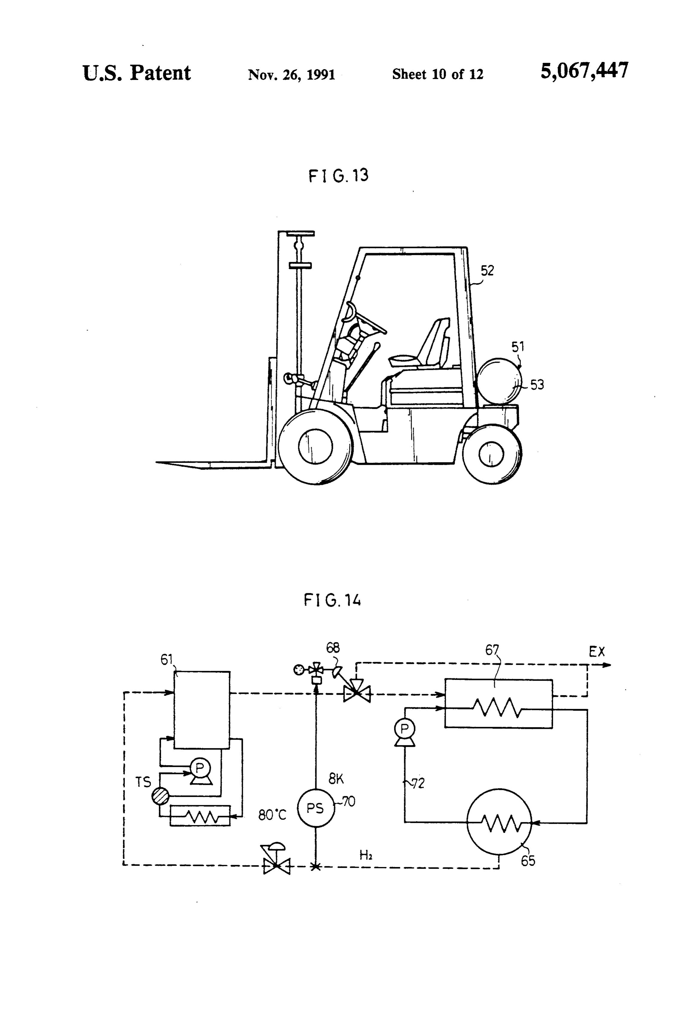
DESCRIPTION OF THE RELATED ART haust heat exchanger 67 and its inflow heat quantity are In FIG. 14 is shown a hydrogen engine system utiliz controlled actuated by by an exhaust adjusting valve 68 which is the signals from a pressure controller 70.
ing metal hydride which is, for example, described in The temperature
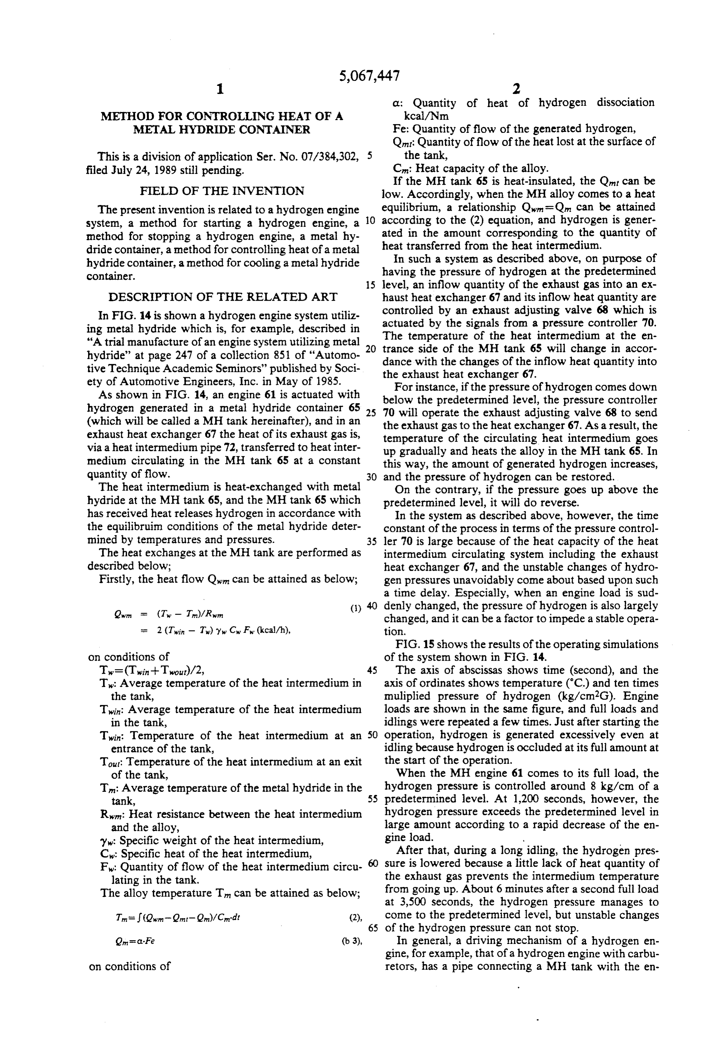
"A trial manufacture of an engine system utilizing metal 20 trance side of theofMH the heat intermedium at the en tank 65 will change in accor hydride' at page 247 of a collection 851 of "Automo dance with the changes of tive Technique Academic Seminors' published by Soci the exhaust heat exchangerthe 67. inflow heat quantity into ety of Automotive Engineers, Inc. in May of 1985. For instance, if the pressure of hydrogen comes down As shown in FIG. 14, an engine 61 is actuated with below hydrogen generated in a metal hydride container 65 25 70 willthe predetermined level, the pressure controller operate the exhaust adjusting valve 68 to send (which will be called a MH tank hereinafter), and in an the exhaust gas to the heat exchanger 67. As a result, the exhaust heat exchanger 67 the heat of its exhaust gas is, temperature of the circulating heat intermedium goes via a heat intermedium pipe 72, transferred to heat inter upgradually and heats the alloy in the MH tank 65. In medium circulating in the MH tank 65 at a constant this way, the amount of generated hydrogen increases, quantity of flow. 30 and the pressure of hydrogen can be restored. The heat intermedium is heat-exchanged with metal On the contrary, if the pressure goes up above the hydride at the MH tank 65, and the MH tank 65 which predetermined level, it will do reverse. has received heat releases hydrogen in accordance with In the system as described above, however, the time the equilibruim conditions of the metal hydride deter constant of the process in terms of the pressure control mined by temperatures and pressures. 35 ler 70 is large because of the heat capacity of the heat The heat exchanges at the MH tank are performed as intermedium circulating system including the exhaust described below; heat exchanger 67, and the unstable changes of hydro Firstly, the heat flow Qin can be attained as below; gen pressures unavoidably come about based upon such a time delay. Especially, when an engine load is sud
denly changed, the pressure of hydrogen is also largely changed, and it can be a factor to impede a stable opera
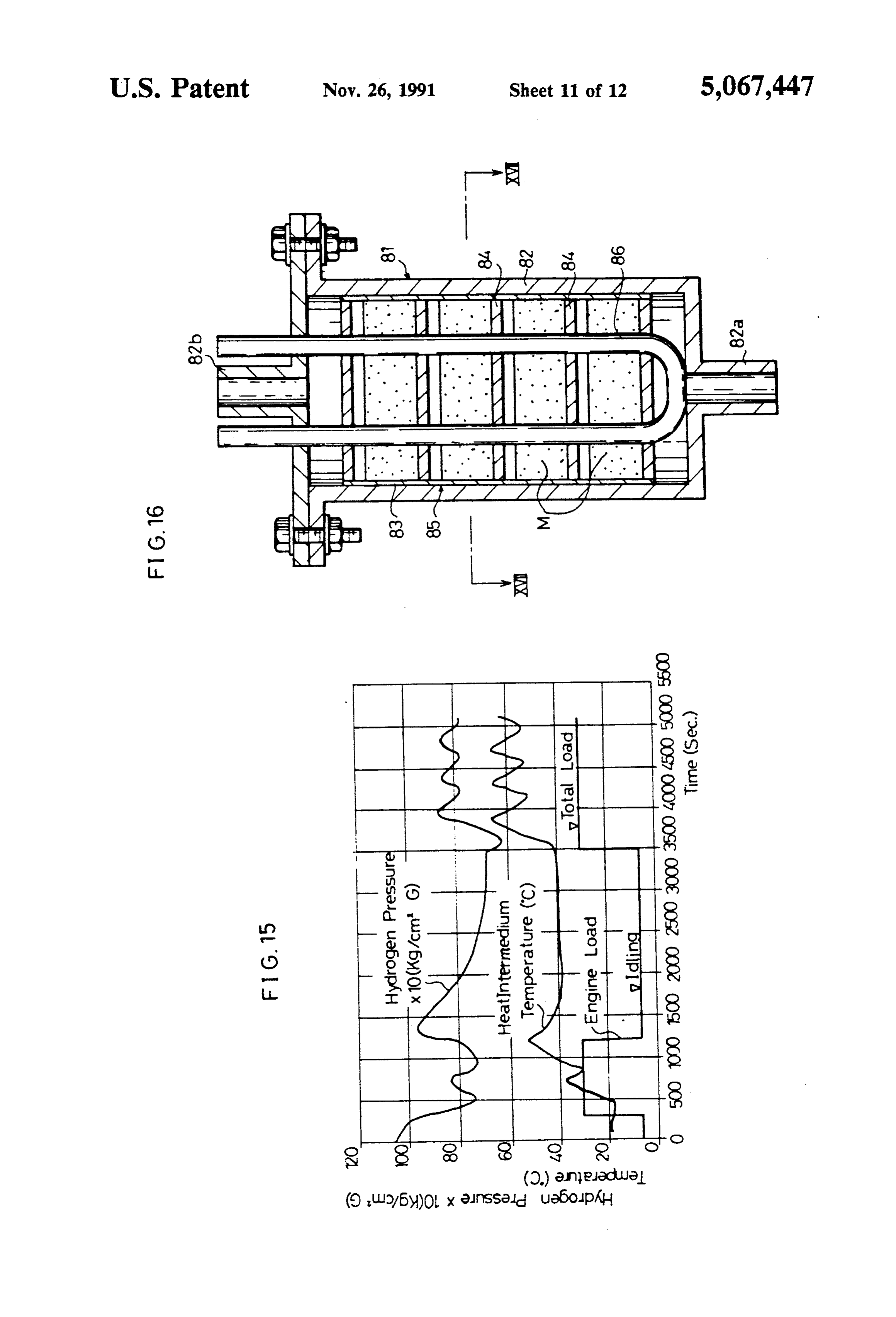
FIG. 15 shows the results of the operating simulations on conditions of of the systern shown in FIG. 14.
Tw=(Twin--Twout)/2, 45 The axis of abscissas shows time (second), and the T: Average temperature of the heat intermedium in axis of ordinates shows temperature (C.) and ten times the tank, muliplied pressure of hydrogen (kg/cm2G). Engine Tin: Average temperature of the heat intermedium loads are shown in the same figure, and full loads and in the tank, idlings were repeated a few times. Just after starting the Tin: Temperature of the heat intermedium at an 50 operation, hydrogen is generated excessively even at entrance of the tank, idling because hydrogen is occluded at its full amount at Tout: Temperature of the heat intermedium at an exit the start of the operation.
of the tank, When the MH engine 61 comes to its full load, the Tn: Average temperature of the metal hydride in the hydrogen pressure is controlled around 8 kg/cm of a tank, 55 predetermined level. At 1,200 seconds, however, the Rn: Heat resistance between the heat intermedium hydrogen pressure exceeds the predetermined level in and the alloy, large amount according to a rapid decrease of the en y: Specific weight of the heat intermedium, gine load.
C: Specific heat of the heat intermedium, After that, during a long idling, the hydrogen pres F: Quantity of flow of the heat intermedium circu sure is lowered because a little lack of heat quantity of lating in the tank. the exhaust gas prevents the intermedium temperature The alloy temperature Tin can be attained as below; at from going up. About 6 minutes after a second full load 3,500 seconds, the hydrogen pressure manages to
Tn= (Qwn-Qnt-Qm)/Crdt (2), come to the predetermined level, but unstable changes 65 of the hydrogen pressure can not stop.
On = c-Fe (b. 3), In general, a driving mechanism of a hydrogen en gine, for example, that of a hydrogen engine with carbu on conditions of retors, has a pipe connecting a MH tank with the en
Page 15
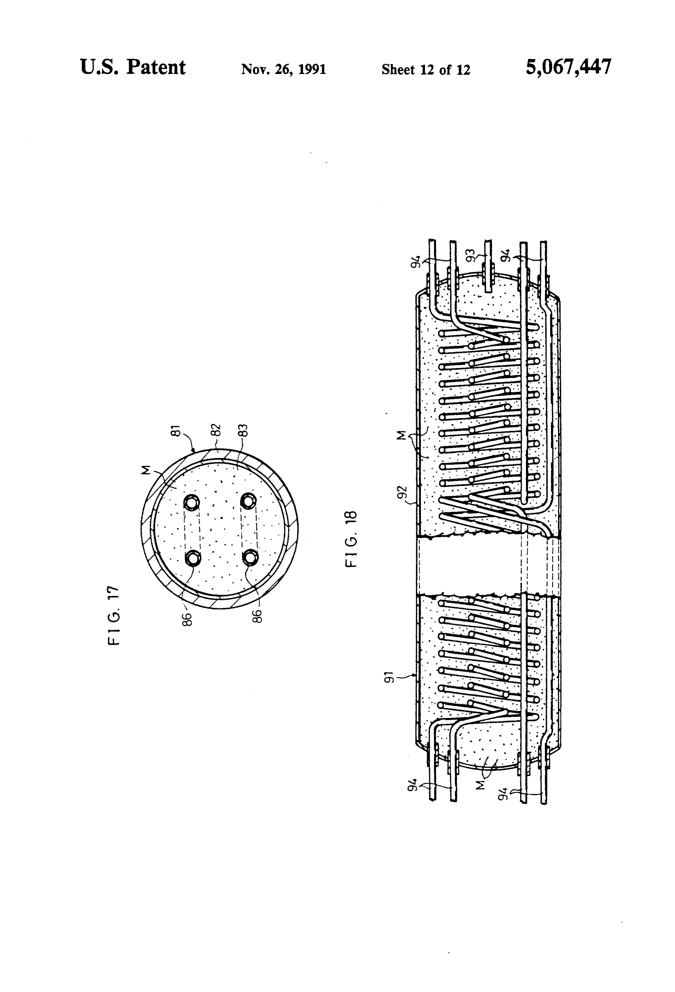
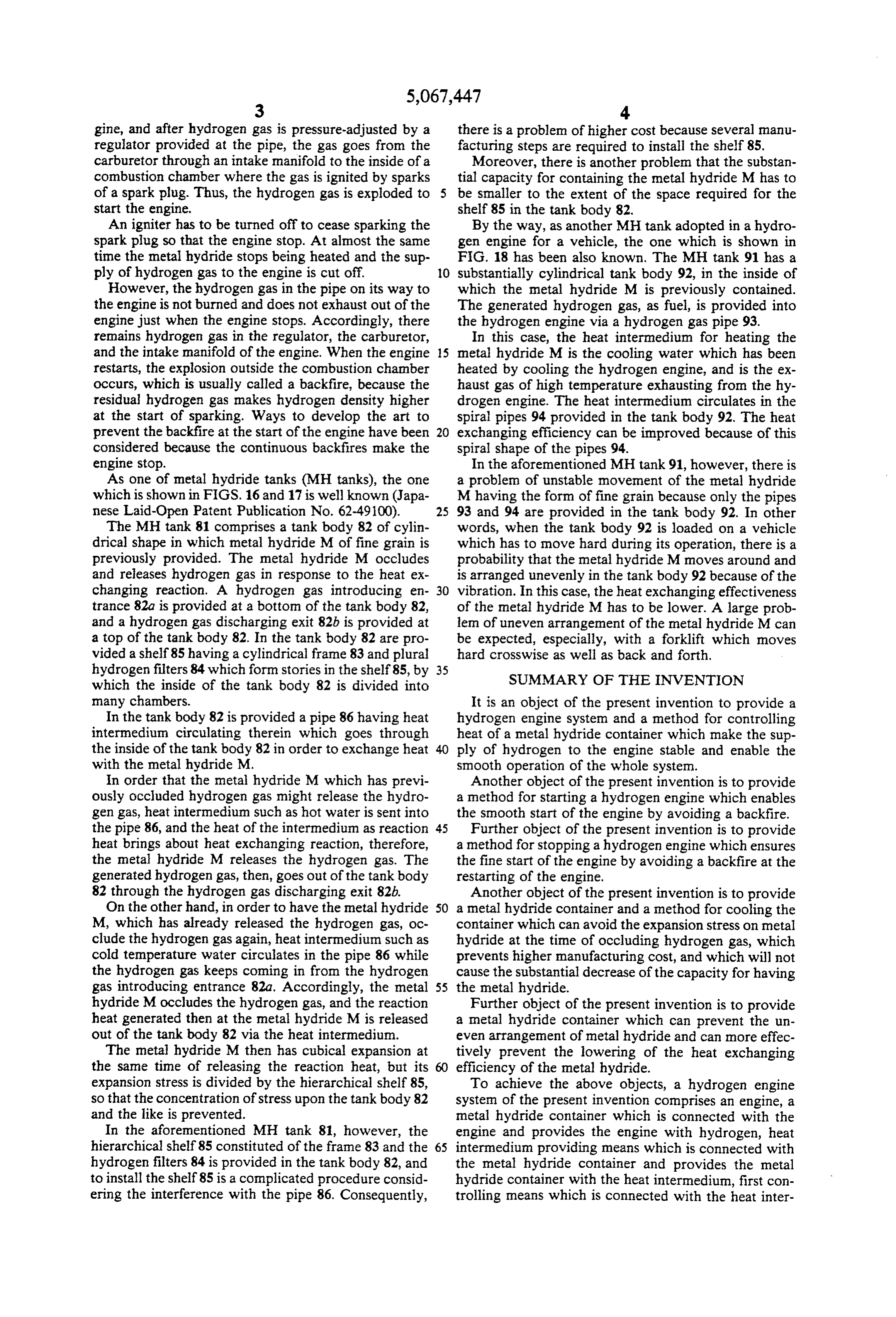
gine, and after hydrogen gas is pressure-adjusted by a there is a problem of higher cost because several manu regulator provided at the pipe, the gas goes from the facturing steps are required to install the shelf 85. carburetor through an intake manifold to the inside of a Moreover, there is another problem that the substan combustion chamber where the gas is ignited by sparks tial capacity for containing the metal hydride M has to of a spark plug. Thus, the hydrogen gas is exploded to be smaller to the extent of the space required for the start the engine. shelf 85 in the tank body 82. An igniter has to be turned off to cease sparking the By the way, as another MH tank adopted in a hydro spark plug so that the engine stop. At almost the same gen engine for a vehicle, the one which is shown in time the metal hydride stops being heated and the sup FIG. 18 has been also known. The MH tank 91 has a ply of hydrogen gas to the engine is cut off. O substantially cylindrical tank body 92, in the inside of However, the hydrogen gas in the pipe on its way to which the metal hydride M is previously contained. the engine is not burned and does not exhaust out of the The generated hydrogen gas, as fuel, is provided into engine just when the engine stops. Accordingly, there the hydrogen engine via a hydrogen gas pipe 93. remains hydrogen gas in the regulator, the carburetor, In this case, the heat intermedium for heating the and the intake manifold of the engine. When the engine 15 metal hydride M is the cooling water which has been restarts, the explosion outside the combustion chamber heated by cooling the hydrogen engine, and is the ex occurs, which is usually called a backfire, because the haust gas of high temperature exhausting from the hy residual hydrogen gas makes hydrogen density higher drogen engine. The heat intermedium circulates in the at the start of sparking. Ways to develop the art to spiral pipes 94 provided in the tank body 92. The heat prevent the backfire at the start of the engine have been 20 exchanging efficiency can be improved because of this considered because the continuous backfires make the spiral shape of the pipes 94. engine stop. In the aforementioned MH tank 91, however, there is As one of metal hydride tanks (MH tanks), the one a problem of unstable movement of the metal hydride which is shown in FIGS. 16 and 17 is well known (Japa M having the form of fine grain because only the pipes nese Laid-Open Patent Publication No. 62-49100). 25 93 and 94 are provided in the tank body 92. In other The MH tank 81 comprises a tank body 82 of cylin words, when the tank body 92 is loaded on a vehicle drical shape in which metal hydride M of fine grain is which has to move hard during its operation, there is a previously provided. The metal hydride M occludes probability that the metal hydride M moves around and and releases hydrogen gas in response to the heat ex is arranged unevenly in the tank body 92 because of the changing reaction. A hydrogen gas introducing en 30 vibration. In this case, the heat exchanging effectiveness trance 82a is provided at a bottom of the tank body 82, of the metal hydride M has to be lower. A large prob and a hydrogen gas discharging exit 82b is provided at len of uneven arrangement of the metal hydride M can a top of the tank body 82. In the tank body 82 are pro be expected, especially, with a forklift which moves vided a shelf 85 having a cylindrical frame 83 and plural hard crosswise as well as back and forth, hydrogen filters 84 which form stories in the shelf 85, by 35 SUMMARY OF THE INVENTION which the inside of the tank body 82 is divided into many chambers. It is an object of the present invention to provide a In the tank body 82 is provided a pipe 86 having heat hydrogen engine system and a method for controlling intermedium circulating therein which goes through heat of a metal hydride container which make the sup the inside of the tank body 82 in order to exchange heat ply of hydrogen to the engine stable and enable the with the metal hydride M. smooth operation of the whole system. In order that the metal hydride M which has previ Another object of the present invention is to provide ously occluded hydrogen gas might release the hydro a method for starting a hydrogen engine which enables gen gas, heat intermedium such as hot water is sent into the smooth start of the engine by avoiding a backfire. the pipe 86, and the heat of the intermedium as reaction 45 Further object of the present invention is to provide heat brings about heat exchanging reaction, therefore, a method for stopping a hydrogen engine which ensures the metal hydride M releases the hydrogen gas. The the fine start of the engine by avoiding a backfire at the generated hydrogen gas, then, goes out of the tank body restarting of the engine.
82 through the hydrogen gas discharging exit 82b. Another object of the present invention is to provide On the other hand, in order to have the metal hydride 50 a metal hydride container and a method for cooling the M, which has already released the hydrogen gas, oc container which can avoid the expansion stress on metal clude the hydrogen gas again, heat intermedium such as hydride at the time of occluding hydrogen gas, which cold temperature water circulates in the pipe 86 while prevents higher manufacturing cost, and which will not the hydrogen gas keeps coming in from the hydrogen cause the substantial decrease of the capacity for having gas introducing entrance 82a. Accordingly, the metal 55 the metal hydride.
hydride Moccludes the hydrogen gas, and the reaction Further object of the present invention is to provide heat generated then at the metal hydride M is released a metal hydride container which can prevent the un out of the tank body 82 via the heat intermedium. even arrangement of metal hydride and can more effec The metal hydride M then has cubical expansion at tively prevent the lowering of the heat exchanging the same time of releasing the reaction heat, but its efficiency of the metal hydride.
expansion stress is divided by the hierarchical shelf 85, To achieve the above objects, a hydrogen engine so that the concentration of stress upon the tank body 82 system of the present invention comprises an engine, a and the like is prevented. metal hydride container which is connected with the In the aforementioned MH tank 81, however, the engine and provides the engine with hydrogen, heat hierarchical shelf 85 constituted of the frame 83 and the 65 intermedium providing means which is connected with hydrogen filters 84 is provided in the tank body 82, and the metal hydride container and provides the metal to install the shelf 85 is a complicated procedure consid hydride container with the heat intermedium, first con ering the interference with the pipe 86. Consequently, trolling means which is connected with the heat inter
Page 16
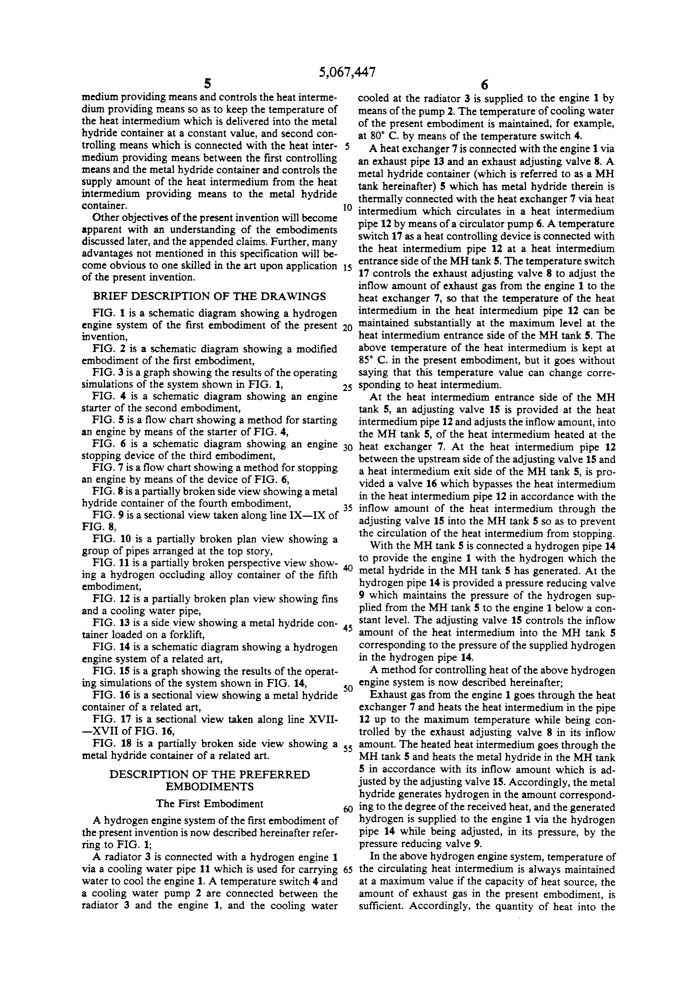
medium providing means and controls the heat interme cooled at the radiator 3 is supplied to the engine 1 by dium providing means so as to keep the temperature of means of the pump 2. The temperature of cooling water the heat intermedium which is delivered into the metal of the present embodiment is maintained, for example, hydride container at a constant value, and second con at 80° C. by means of the temperature switch 4. trolling means which is connected with the heat inter- 5 A heat exchanger 7 is connected with the engine 1 via medium providing means between the first controlling an exhaust pipe 13 and an exhaust adjusting valve 8. A means and the metal hydride container and controls the metal hydride container (which is referred to as a MH supply amount of the heat intermedium from the heat intermedium providing means to the metal hydride tank hereinafter) 5 which has metal hydride therein is thermally connected with the heat exchanger 7 via heat container. 10 intermedium which circulates in a heat intermedium Other objectives of the present invention will become pipe apparent with an understanding of the embodiments switch1217 by means of a circulator pump 6. A temperature as a heat controlling device is connected with discussed later, and the appended claims. Further, many the heat intermedium pipe 12 at a heat intermedium advantages not mentioned in this specification will be come obvious to one skilled in the art upon application 15 entrance side of the MH tank 5. The temperature switch 17 controls the exhaust adjusting valve 8 to adjust the of the present invention.
inflow amount of exhaust gas from the engine 1 to the
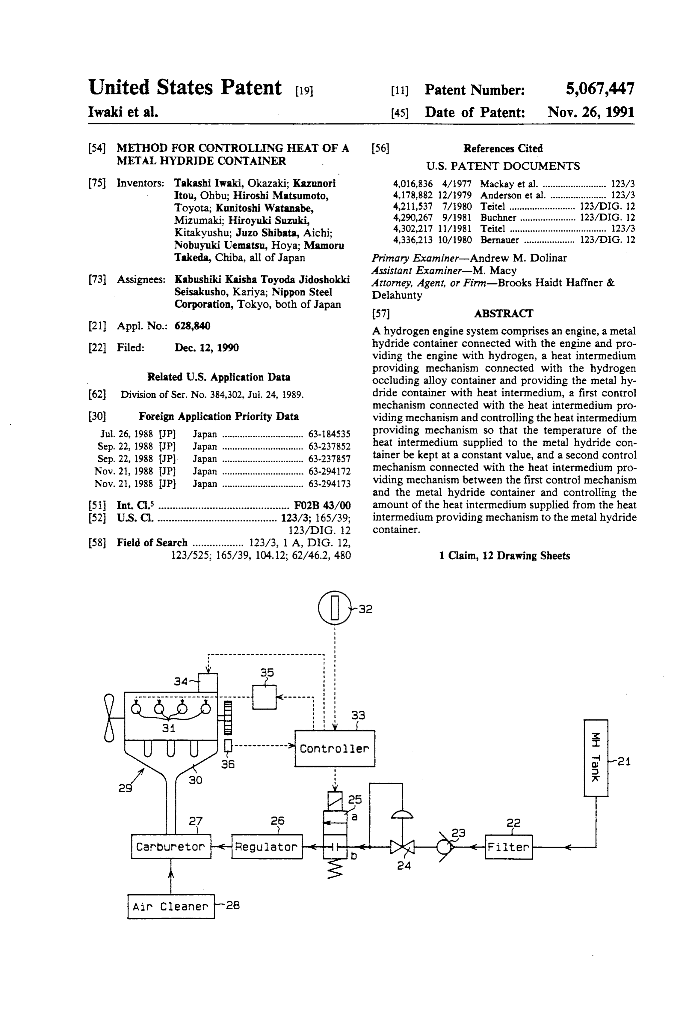
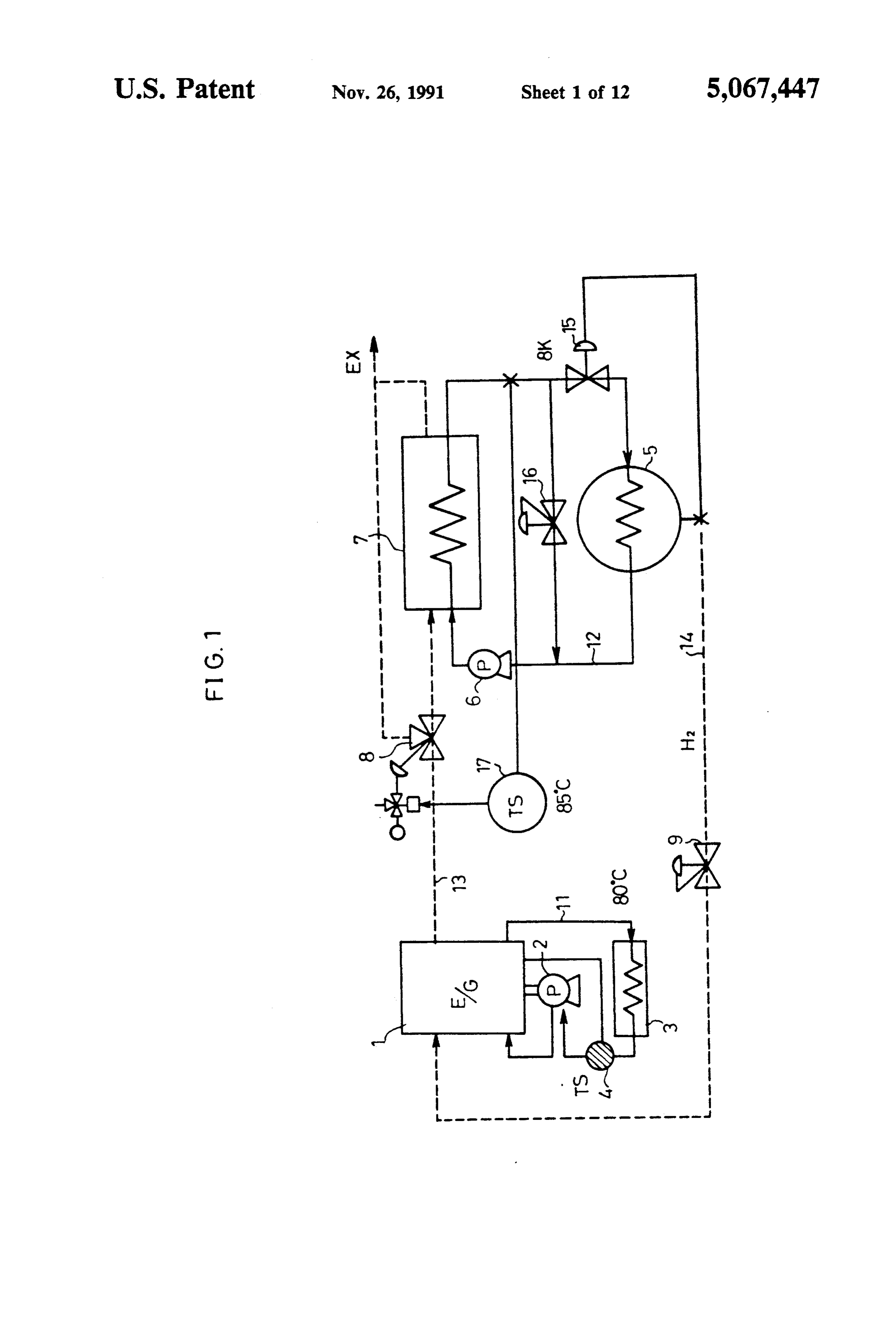
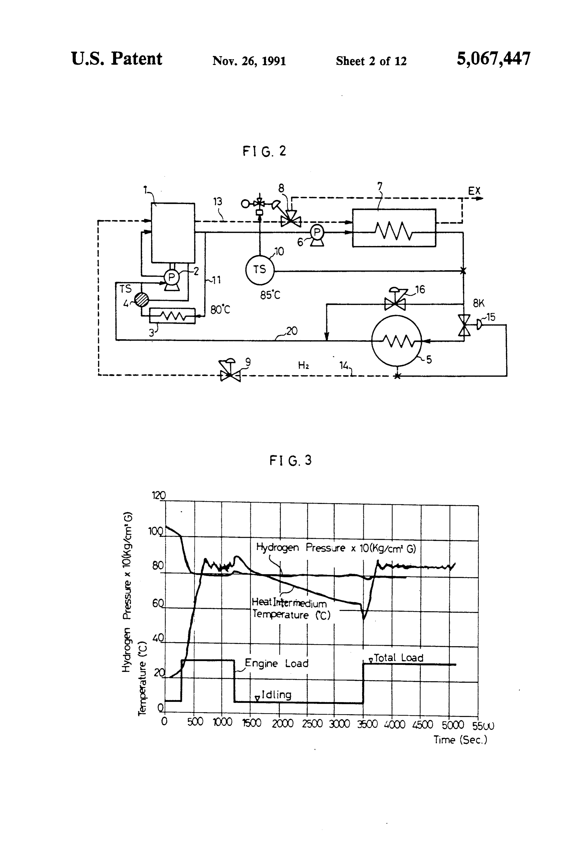
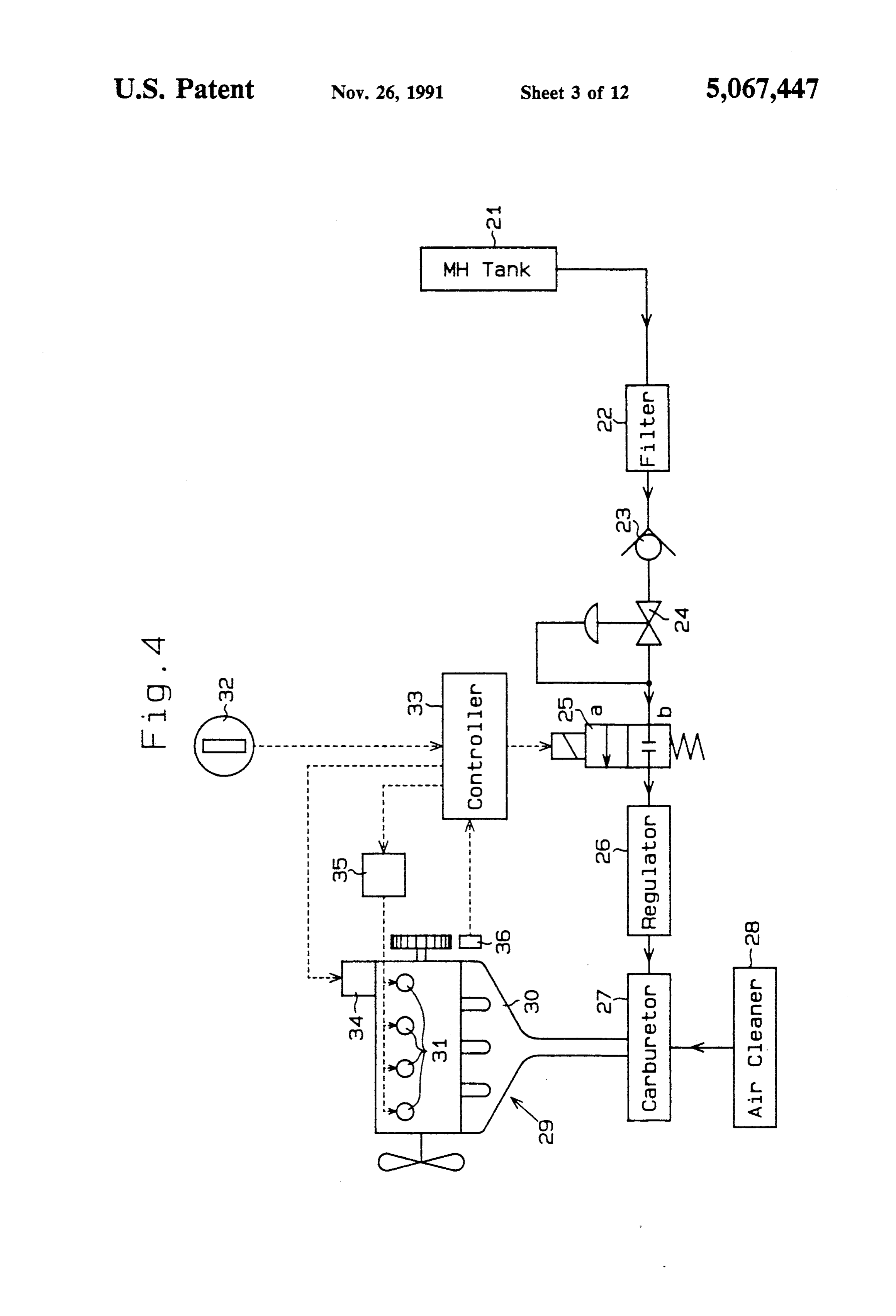
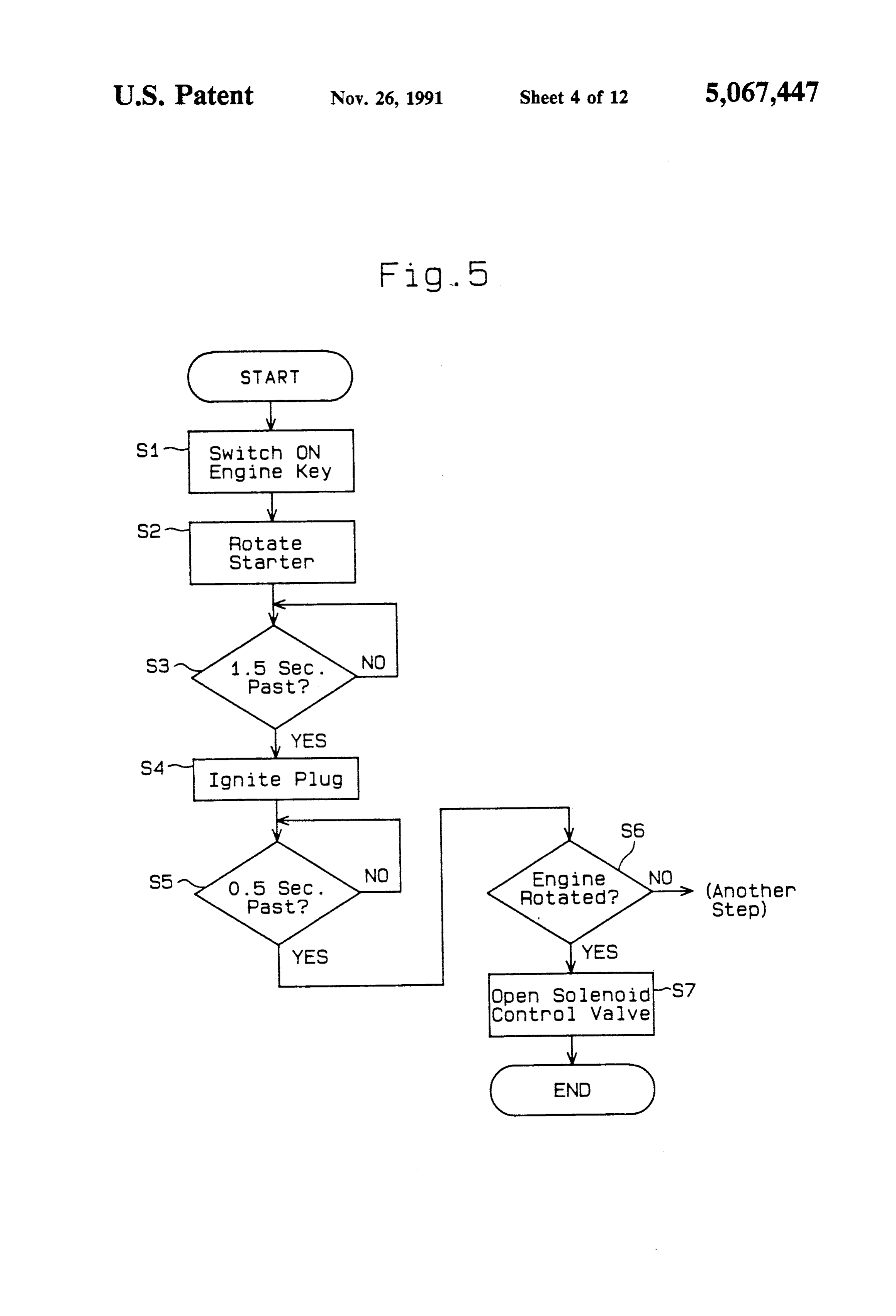
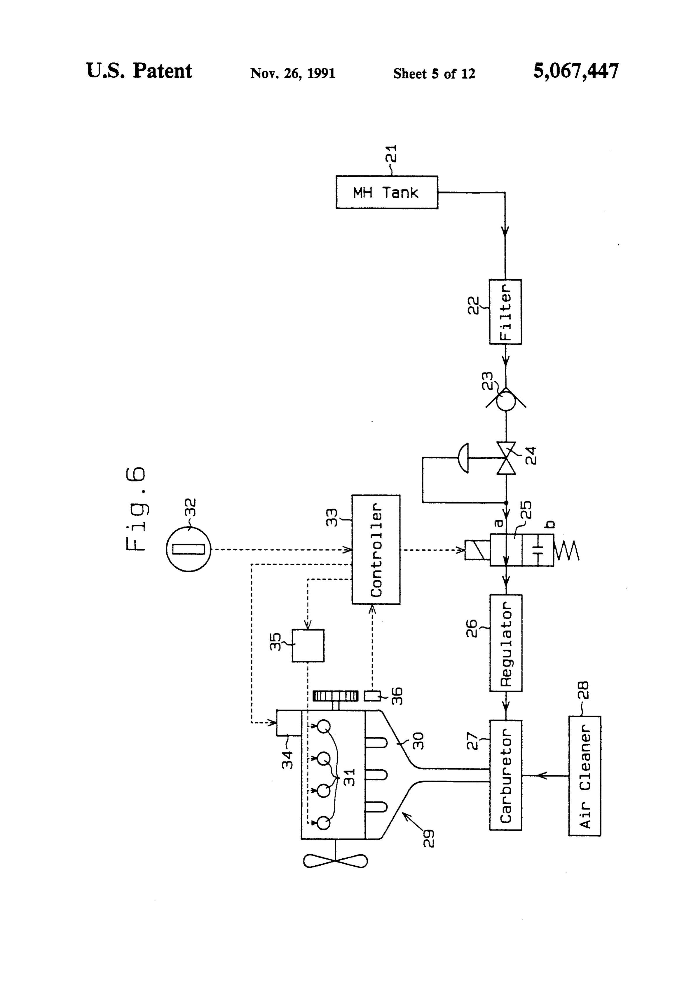
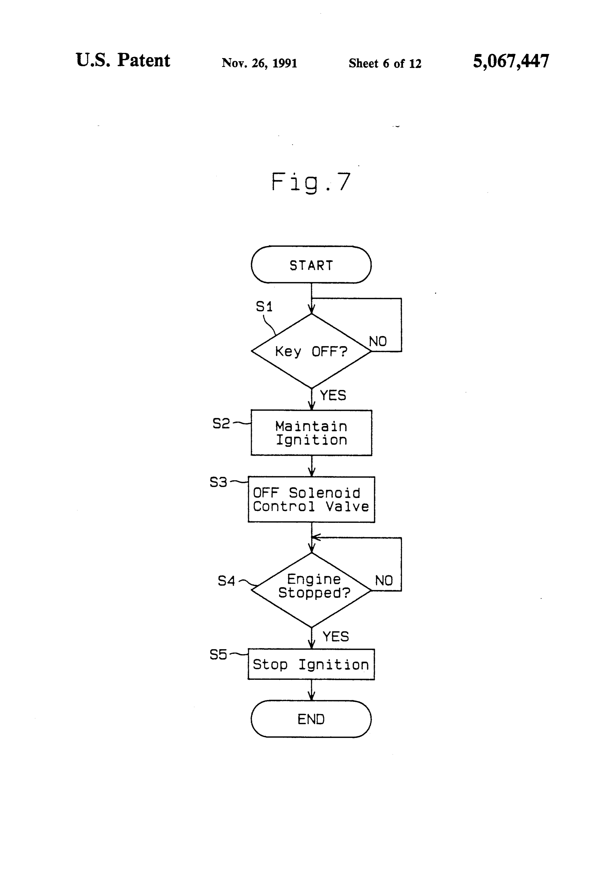
BRIEF DESCRIPTION OF THE DRAWINGS heat exchanger 7, so that the temperature of the heat FIG. 1 is a schematic diagram showing a hydrogen intermedium in the heat intermedium pipe 12 can be engine system of the first embodiment of the present 20 maintained substantially at the maximum level at the invention, heat intermedium entrance side of the MH tank 5. The FIG. 2 is a schematic diagram showing a modified above temperature of the heat intermedium is kept at embodiment of the first embodiment, 85 C. in the present embodiment, but it goes without FIG. 3 is a graph showing the results of the operating saying that this temperature value can change corre simulations of the system shown in FIG. 1, 25 sponding to heat intermedium. FIG. 4 is a schematic diagram showing an engine At the heat intermedium entrance side of the MH starter of the second embodiment, tank 5, an adjusting valve 15 is provided at the heat FIG. 5 is a flow chart showing a method for starting intermedium pipe 12 and adjusts the inflow amount, into an engine by means of the starter of FIG. 4, the MH tank 5, of the heat intermedium heated at the FIG. 6 is a schematic diagram showing an engine 30 heat exchanger 7. At the heat intermedium pipe 12 stopping device of the third embodiment, between the upstream side of the adjusting valve 15 and FIG. 7 is a flow chart showing a method for stopping a heat intermedium exit side of the MH tank 5, is pro an engine by means of the device of FIG. 6,
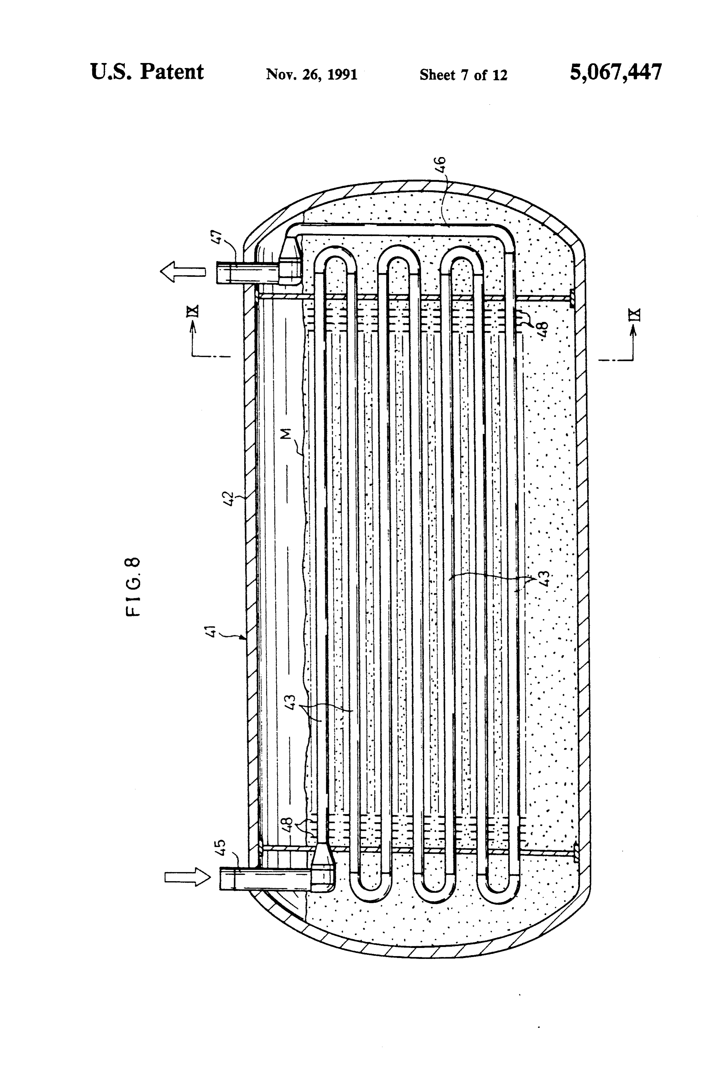
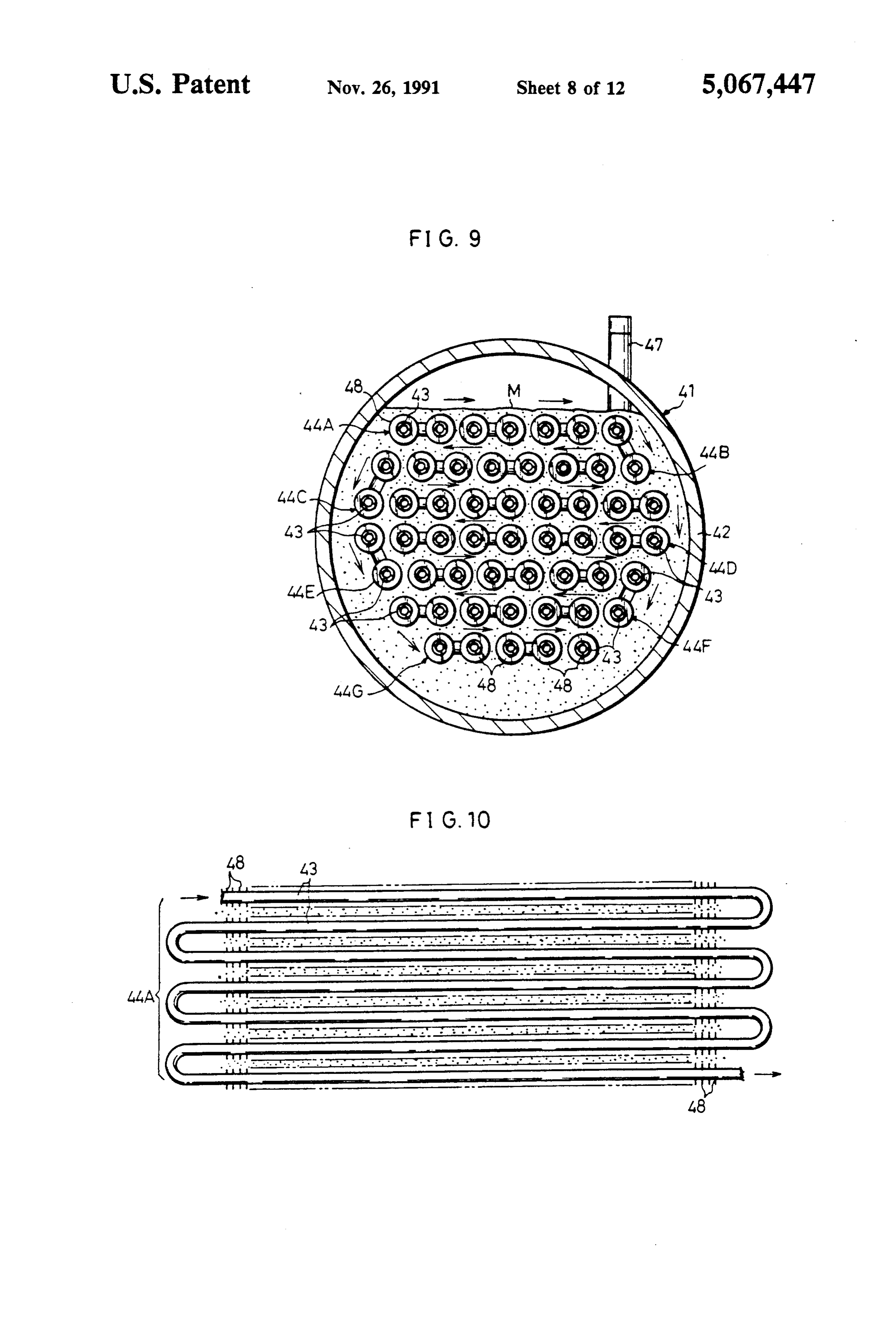
FIG. 8 is a partially broken side view showing a metal vided in the a valve 16 which bypasses the heat intermedium heat intermedium pipe 12 in accordance with the hydride container of the fourth embodiment, 35 inflow amount of the heat intermedium through the FIG. 9 is a sectional view taken along line IX-IX of adjusting valve 15 into the MH tank 5 so as to prevent
FIG. 10 is a partially broken plan view showing a theWith circulation of the heat intermedium from stopping. the MH tank 5 is connected a hydrogen pipe 14 group of pipes arranged at the top story, to provide
FIG 11 is a partially broken perspective view show metal hydride the engine 1 with the hydrogen which the ing a hydrogen occluding alloy container of the fifth hydrogen in the MH tank 5 has generated. At the embodiment, pipe 14 is provided a pressure reducing valve FIG. 12 is a partially broken plan view showing fins 9 which maintains the pressure of the hydrogen sup and a cooling water pipe, plied from the MH tank 5 to the engine 1 below a con FIG. 13 is a side view showing a metal hydride con stant level. The adjusting valve 15 controls the inflow tainer loaded on a forklift, amount of the heat intermedium into the MH tank 5 FIG. 4 is a schematic diagram showing a hydrogen corresponding to the pressure of the supplied hydrogen engine system of a related art, in the hydrogen pipe 14.
FIG. 15 is a graph showing the results of the operat A method for controlling heat of the above hydrogen ing simulations of the system shown in FIG. 14, 50 engine system is now described hereinafter; FIG. 16 is a sectional view showing a metal hydride Exhaust gas from the engine 1 goes through the heat container of a related art, exchanger 7 and heats the heat intermedium in the pipe FIG. 17 is a sectional view taken along line XVII 12 up to the maximum temperature while being con -XVII of FIG. 16, trolled by the exhaust adjusting valve 8 in its inflow FIG. 18 is a partially broken side view showing a 55 amount. The heated heat intermedium goes through the metal hydride container of a related art. MH tank 5 and heats the metal hydride in the MH tank DESCRIPTION OF THE PREFERRED 5 in accordance with its inflow amount which is ad EMBODIMENTS justed by the adjusting valve 15. Accordingly, the metal hydride generates hydrogen in the amount correspond
The First Embodiment 60 ing to the degree of the received heat, and the generated A hydrogen engine system of the first embodiment of hydrogen is supplied to the engine 1 via the hydrogen the present invention is now described hereinafter refer pipe 14 while being adjusted, in its pressure, by the ring to FIG. 1; pressure reducing valve 9.
A radiator 3 is connected with a hydrogen engine 1 In the above hydrogen engine system, temperature of via a cooling water pipe 11 which is used for carrying 65 the circulating heat intermedium is always maintained water to cool the engine 1. A temperature switch 4 and at a maximum value if the capacity of heat source, the a cooling water pump 2 are connected between the amount of exhaust gas in the present embodiment, is radiator 3 and the engine 1, and the cooling water sufficient. Accordingly, the quantity of heat into the
Page 17
MH tank 5 is adjusted by changing the inflow annount of the hydrogen engine system of the present modified the heat intermedium into the MH tank 5. embodiment is suitable for the vehicle, which usually In a method for controlling heat of a hydrogen engine runs at low speed and tends to have its engine over system of a related art as shown in FIG. 14, the quantity heated, such as a forklift because the cooling of the of heat into a MH tank is adjusted by heightening and engine 1 is sufficiently performed by both the radiator 3 lowering the temperature T of warm water according and the MH tank 5.
to the equation (1). On the other hand, in the method for In the aforementioned modified embodiment, the controlling heat in the present embodiment, the quan heat intermedium delivered from the engine 1 by the tity of heat into the MH tank 5 is controlled by chang circulator pump 6 can be supplied directly to the MH ing the inflow amount F of warm water. O tank 5 without passing through the heat exchanger 7, so Consequently, the unstable changes of hydrogen that the heat exchanger 7 can be left out. Consequently, pressure can be lessened because the inflow amount of the size of the hydrogen engine system can be smaller. the heat intermedium into the MH tank 5 can be in The Second Embodiment stantly increased and decreased by opening and closing the adjusting valve 15 which has a quick response to the 5 The hydrogen engine system of the second embodi drastic changes on the amount of the hydrogen being ment of the present invention is described hereinafter in used. At a sudden drop of the load of the engine 1 dur details referring to FIGS. 4 and 5; ing idling or the like, the abnormal increase of hydrogen As shown in FIG. 4, metal hydride is contained in a pressure can be minimized when the inflow of the heat MH tank 21, and generates hydrogen gas while being intermedium into the MH tank 5 is stopped because the 20 heated by exhaust gas, cooling water of high tempera sensible heat of the heat intermedium in the MH tank 5 ture which has been heated by cooling an engine and so is low. on. A filter 22 communicating with the MH tank 21 As described above, the method of the present em removes foreign materials such as fine alloy powders bodiment for controlling heat can lower the unstable mixed in the hydrogen gas. The purified hydrogen gas is changes of hydrogen pressure, which often occur in the 25 delivered to a pressure reducing valve 24 via a nonre related art due to the sudden change of the load. turn valve 23 arranged at a lower stage. The nonreturn FIG. 3 shows the results of the operating simulations valve 23, when backfire occurs, prevents the flame from with the method of the present embodiment for control entering the MH tank 21. The pressure reducing valve ling heat by using the same facility under the same 24 delivers the hydrogen gas to an electromagnetic operating conditions as those of the operating simula 30 control valve 25 after reducing the pressure of the hy tions of the hydrogen engine system as shown in FIG. drogen gas to the level which is predetermined based on 15. the safety of a pipe and so on. As shown in FIG. 3, the pressure exceeds the prede The electromagnetic control valve 25 can be changed termined level just after starting the operation because over between two positions, a position a and a position of the reasons as explained above. The hydrogen pres 35 b. At the position b shown in FIG. 4, the hydrogen gas sure after a full load operation is, however, shown to be delivered from the pressure reducing valve 24 is pre extremely stable. vented from flowing downstream. When the electro The gradual decrease of the heat intermedium tem magnetic control valve 25 is changed over to the posi perature during a long idling is due to the lack of the tion a, the hydrogen gas is pressure-adjusted approxi quantity of heat supplied from the engine 1. But if the mately to the atmospheric pressure at a regulator 26 quantity of heat is sufficient, the temperature of the heat arranged at a lower stage, and then is delivered to a intermedium is maintained exactly at 85 C. carburetor 27 at a lower stage. In the carburetor 27, the In the modified embodiment of the first embodiment hydrogen gas is mixed with the air coming through an as shown in FIG. 2, a heat intermedium pipe 20 at the air cleaner 28. The hydrogen gas, then, goes through an heat intermedium exit side of the MH tank 5 is con 45 intake manifold 30, and is compressed into a combustion nected with the cooling water pump 2 for delivering chamber (not shown). In the combustion chamber, the cooling water to the engine 1 instead of being con hydrogen gas is burned at the sparking of a spark plug nected with the circulator pump 6 which has the heat 31.
intermedium circulate. On the other hand, the circula An electric formation for actuating the electromag tor pump 6 is connected with the cooling water pipe 11 50 netic control valve 25 is now described; and delivers the hot cooling water as the heat interme A controller 33 actuates and stops a starter 34 of an dium, which has been heated while cooling the engine, engine 29 based on the on and off operations of an en into the MH tank 5 by way of the heat exchanger 7 and gine key switch 32, and further ignites and stops igniting the adjusting valve 15. The rest of the structure is the the spark plug 31 by means of an ignitor 35 while count same as that of the first embodiment. 55 ing time by means of a built-in timer therein according In the modified embodiment, the cooling water as the to a prestored program. The controller 33 outputs sig heat intermedium which passes through the MH tank 5 nals to the electromagnetic control valve 25 to magne is cooled down due to the endothermic effect, when tize and demagnetize the valve 25, and changes over the hydrogen being generated, of the metal hydride in the valve 25 to either the position a or the position b, so that MH tank 5. The heat intermedium is, then, supplied to the MH tank 21 and the engine 29 communicate with the engine 1 via the cooling water pump 2, and cools the each other or are cut off from each other. The control engine 1 with the cooling water from the radiator 3. ler 33 is also connected with an engine rotation sensor Namely, the MH tank 5 as a heat sink assists the cooling 36 which detects the rotation of the engine 29, and effect of the radiator 3 on the engine 1. Accordingly, monitors the rotation of the engine 29 according to the capacity and the size of the radiator 3 can be small, 65 signals from the rotation sensor 36. so that the hydrogen engine system and consequently A method for controlling the start of the engine 29 as the whole vehicle which loads the hydrogen engine composed and formulated above is now described refer. system can be manufactured in Small size. Moreover, ring to FIG. 5.
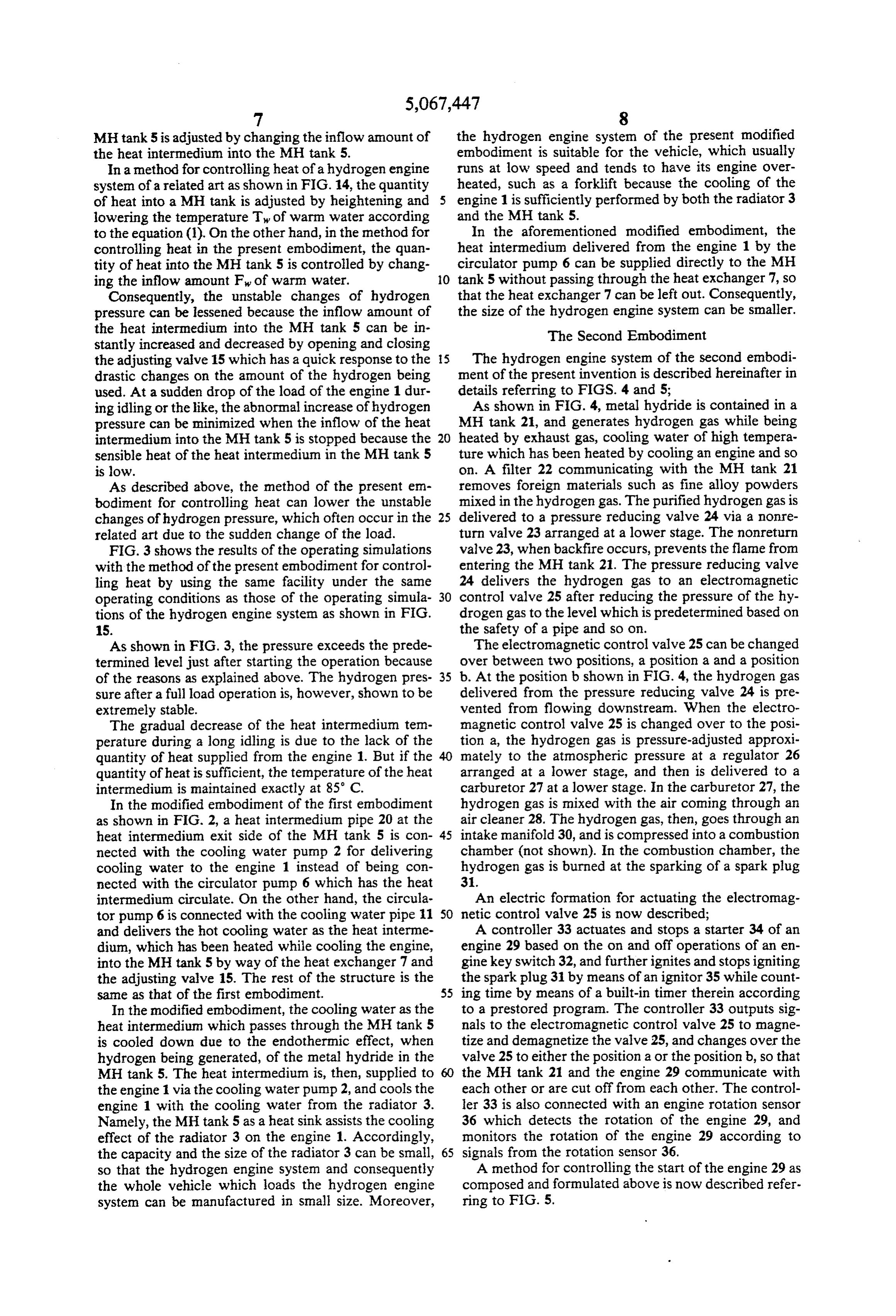
Page 18
Now, the engine 29 is being stopped, the electromag valve 25 waits for 0.5 seconds after the sparking of the netic control valve 25 is kept at the position b, and the spark plug 31 to open. The electromagnetic control MH tank 21 and the engine 29 are being cut off from valve 25, however, can open either at sparking or just each other. Then, when the key switch 32 is turned on before sparking as far as there is timing, at the start of to start the engine 29, the controller 33 confirms it at the engine 29, to make it sure to have the first explosion step S1 (Steps are referred to as Shereinafter.), and after the hydrogen gas which has remained in the intake rotates the starter 34 to rotate the engine 29 idle at S2. manifold 30 and in the engine 29 or so since the last stop The residual hydrogen gas, which has remained in the of the engine 29 exhausts out of the engine 29. regulator 26, the carburetor 27, and the intake manifold Moreover, in the present embodiment, the judgment 30 since the last stop of the engine 29, therefore exhausts 10 whether the residual hydrogen gas is still there or not is out of the engine 29. The controller 33 counts the time made based on time, but by means of detecting the of the idle rotation of the engine 29, and waits for a number of rotations of the engine 29 rotated by the certain amount of time (It is 1.5 seconds in the present starter 34, the judgment on the presence of the residual embodiment) till the hydrogen gas which has remained since the last stop of the engine is completely exhausted. 15 hydrogen gas can be made based on the number of After this amount of time has passed, the controller 33 rotations.
sparks the sparkplug 31 via the ignitor 35 at the next S4. The Third Embodiment Moreover, after the predetermined time (0.5 seconds) The third embodiment of the present invention is has passed at S5, namely, at the time when the spark now described hereinafter referring to FIGS. 6 and 7. plug 31 is completely ready for being sparked, at S6 the controller 33 checks, by means of signals from the en ping thepresent
The embodiment shows a method for stop same hydrogen engine system as that of the gine rotation sensor 36, whether the engine 29 is surely second embodiment.
rotating or not. This is for avoiding such situation as the hydrogen gas is supplied to the engine 29 while the As shown in FIG. 6, the electromagnetic control engine 29 is not rotating because the starter 34 does not 25 valve 25 is kept at the position a, and the engine 29 runs rotate due to the death of the battery and so on. When with the hydrogen gas supplied from the MH tank 21. it is judged that the engine 29 is rotating, the controller When the key switch 32 is turned off to stop the engine 33 sends signals to the electromagnetic control valve 25 29, the controller 33 confirms it at the step S1 (Step will at S7, and magnetizes the electromagnetic control valve be referred to as Shereinafter.), and changes the posi 25 to change the positions from the position b to the 30 tions of the electromagnetic control valve 25 from the position a. Then, the MH tank 21 and the engine 29 position a to the position b to cut off the MH tank and come to communicate with each other, and the hydro the engine 29 from each other at S3 while driving the gen gas is delivered for the engine 29. Consequently, ignitor 35 to keep the spark plug 31 of the engine 29 in after the hydrogen gas is mixed with the air in the car sparking condition at S2. Accordingly, the hydrogen buretor 27, the first explosion is performed in the com 35 gas no longer remains in the regulator 26, the carburetor bustion chamber of the engine 29, and the engine 29 27, the intake manifold 30 and so on because all the starts running. By the way, when it is sensed that the hydrogen gas remaining at the downstream side of the engine 29 is not rotating at S6, the starter 34 and so on electromagnetic control valve 25 is compressed into the are considered to be out of order, and the controller 33 combustion chamber (not shown) with sucking actions takes different actions which are not described in the of a piston (not shown) moving in the engine 29 and is present embodiment. burned therein to exhaust into the atmosphere. The engine 29 can stop as the key switch 32 is turned After the aforementioned residual hydrogen gas ex off to stop sparking the spark plug 31 and to change the hausts out of the engine 29, if the controller 33 judges, positions of the electromagnetic control valve 25 from according to the signals from the engine rotation sensor the position a to the position b via the controller 33, and 45 36, that the engine 29 stops rotating at S4, the controller as the metal hydride in the MH tank 21 stops being 33 stops sparking the spark plug 31 via the ignitor 35 heated in an appropriate way.
As described above, the backfire is certainly pre andIncompletes the method the stopping operation of the engine 29.
for stopping the engine 29 as described vented in the aforementioned embodiment because the hydrogen gas remaining between the electromagnetic SO above, all the hydrogen gas remaining in a route from the electromagnetic control valve 25 to the combustion control valve 25 and the combustion chamber of the engine 29 completely exhausts out of the engine 29 by chamber of the engine 29 is compressed into the com rotating the engine 29 idle prior to the real start of the bustion chamber and is exploded to exhaust after the hydrogen gas stops being supplied from the MH tank 21 engine 29.
Though the present embodiment is composed in such 55 to the engine 29 by means of a changing operation of the a way that the electromagnetic control valve 25 is electromagnetic control valve 25. Consequently, no changed over between the positions a and b by the hydrogen gas remains in the engine 29 and its driving controller 33 either to have the MH tank 21 and the circuit at the stop of the engine 29, so that the backfire engine 29 communicate with each other or to have then due to the residual hydrogen gas can be avoided when cut off from each other, it is also possible to have such the engine 29 starts again.
a formulation instead that the controller 33 has duty In the present embodiment, the sparking operation is control on the electromagnetic control valve 25 at the finished after the engine 29 stops, but it can be modified, start of the engine 29 to gradually increase the amount for example, as described below;
of the hydrogen gas flowing into the combustion cham (1) The sparking number, after the electromagnetic ber and to have the first explosion smoothly. 65 control valve 25 closes, of each cylinder of the engine In the present embodiment, in order to supply the 29 is determined previously, and the sparking operation hydrogen gas under the condition where the hydrogen does not continue after sparking is performed in the gas is able to be ignited, the electromagnetic control predetermined number.
Page 19
(2) Once the engine 29 rotates in the predetermined through the hydrogen gas introducing entrance (not number after the electromagnetic control valve 25 shown), and the low temperature water is also led into closes, the sparking operation no longer continues. the tank body 42 through the low temperature water The Fourth Embodiment introducing entrance 45. At this time, the metal hydride M, as shown in FIGS. 8 and 9, is agglomerated and is in
A metal hydride tank (a MH tank) of the fourth en a state of agglomerate layer leaving a little space at the bodiment of the present invention is now described in top portion of the inside of the tank body 42 because of details hereinafter referring to FIGS. 8-10. having released the hydrogen gas. As shown in FIGS. 8 and 9, a MH tank 4 has a The low temperature water led through the low tem cylindrical tank body 42 containing the metal hydride O perature water introducing entrance 45 is firstly led to M of fine grain which releases and/or occludes hydro one end of the group of pipes 44A at the top story and gen gas in reversible reactions accompanied with heat goes to the group of pipes 44B at the next lower story exchanges. In the tank body 42 are provided pipes 43 after running zigzag along the pipe 43 of the group of which act as cooling intermedium circulating routes pipes 44A at the top story. The low temperature water going through the inside of the tank body 42 and con 15 also runs zigzag along the pipe 43 of the group of pipes ing back to the hydrogen engine (not shown) in order to 44B and goes to the group of pipes 44C at the next heat or cool the metal hydride M. The pipes 43 contrib lower story. The low temperature water successively ute to the heat exchanging reaction by having low ten goes from the group of pipes 44C to the group of pipes perature water as cooling intenedium circulate therein 44G at the bottom story and then is led out of the tank when the metal hydride M occludes the hydrogen gas. 20
When the metal hydride M releases the hydrogen gas, body ature 42 via the connecting pipe 46 and the low temper water discharging exit 47. Accordingly, the low the pipes 43 also contribute to the heat exchanging temperature reaction by having high temperature water (for exam portion to thewater lower gradually moves from the upper portion of the tank body 42 while ple, the cooling water which has become of high tem moving in the longitudinal direction of the tank body 42 perature after cooling the hydrogen engine) as heating 25 via the groups of pipes 44A-44G as shown as arrows in intermedium circulate therein. The released hydrogen FIG 9.
gas is supplied to the hydrogen engine via a hydrogen A reaction equation on the hydrogen gas (H2) occlu gas pipe (not shown).
In the present embodiment, the pipes 43 are provided sion of the metal hydride M can be shown as follows; in the tank body 42 in plural lines in parallel to extend in 30 the longitudinal direction thereof and in plural stories vertically.
Namely, as shown in FIG. 9, groups of pipes In Accordingly, the above equation, Q means reaction heat. one of the important things on the hy 44A-44G made of plural lines of the pipes 43 are pro drogen gas occlusion is to release the reaction heat Q vided in the tank body 42 from the top portion to the 35 out of the tank body 42 lower portion thereof in many stories. As shown in reaction heat Q from theeffectively, and removing the FIG. 10, in each of the groups of pipes 44A-44G, the promotes the hydrogen gas occlusion 42 tank body outstandingly pipes 43 are connected with each other in zigzag shape dride M. Another important thing is the the of metal hy relaxation of in its plan view. Moreover, as shown in FIG. 8, one end the expansion stress on the agglomerate metal hydride of each group of pipes 44A-44G in each story is succes M, which has not been reacted, at the hydrogen gas
sively connected with the other end of each group 44A-44G in such a way as the group of pipes 44A is occluding reaction.
connected with the group of pipes 44B which is ar In the present embodiment, the hydrogen gas occlu ranged just below the group of pipes 44A, the group of sion by the metal hydride M, namely, the heat exchang pipes 44B is connected with the group of pipes 44C, and 45 ing reaction begins around the group of pipes 44A at the the other groups such as the group of pipes 44D, the top story which the low temperature water firstly group of pipes 44E, the group of pipes 44F, and the comes through and which the reaction heat is firstly group of pipes 44G at the bottom story are successively absorbed by, and gradually proceeds downward to an connected with each other in a same manner in order to area around the group of pipes 44G at the bottom story. have the low temperature water go from one group to 50 The cubical expansion of the metal hydride M accom another. panied with the hydrogen gas occlusion successively As shown in FIG. 8, a low temperature water intro proceeds from the upper portion to the lower portion of ducing entrance 45 is provided at one end of the group the nonreacted agglomerate layer of the metal hydride of pipes 44A at the top story, and a low temperature M which is agglomerated in the tank body 42. In other water discharging exit 47 is provided at one end of the 55 words, the cubical expansion of the metal hydride M group of pipes 44G at the botton story via a connecting begins at the upper portion of the tank body 42 where pipe 46 extending upward. there is sufficient room for the expansion, and gradually A number offins 48 of disc shape are provided at both comes down to the lower portion.
sides of each pipe 43 in the longitudinal direction As a result, the hydrogen gas occlusion by the metal thereof along the length of the pipes 43. The fins 48 are hydride M can be performed with the room where the arranged having a predetermined interval between one nonreacted agglomerate metal hydride M escapes. In another, and the metal hydride M can be filled in the other words, the hydrogen gas can be occluded while intervals. The fins 48, therefore, do not have any sub avoiding the generation of residual stress in the agglom stantial influence on the capacity for containing the erate layer of the nonreacted metal hydride M. The metal hydride M. 65 expansion stress on the nonreacted metal hydride M In case that the metal hydride M which has already agglomerated at the lower portion of the tank body 42 released the hydrogen gas occludes the hydrogen gas is relaxed and, therefore, the stress concentration on the again, the hydrogen gas is led into the tank body 42 tank body 42 and the pipes 43 or so can be relaxed.
Page 20
Moreover, in the present embodiment, the plural fins 44A at first and runs through the group of pipes 44G at 48 are provided at the pipes 43, so that the metal hy last.
dride M is cooled effectively because of those fins 48 (4) Though the MH tank 41 is used for a hydrogen and that the efficiency of the heat exchange on the engine system in the present embodiment, it can be metal hydride M is improved. applied for all the apparatuses and devices, other than Furthermore, the movement of the metal hydride M the hydrogen engine system, which need the supply of can be restricted though the tank body 42 vibrates in the hydrogen gas.
longitudinal direction thereof, namely, in the direction The Fifth Embodiment along which the pipe 43 extends. In other words, the movement of the metal hydride M in the longitudinal 10 The fifth embodiment of the present invention em direction of the tank body 42 is restricted and the metal bodied in a MH tank of a hydrogen engine for a forklift hydride M can be prevented from being arranged un is now described in details hereinafter referring to evenly in the tank body 42. FIGS. 11 to 13.
In the present embodiment as described above, the 15 As shown in FIG. 13, a MH tank 51 of the present expansion stress on the metal hydride M can be relaxed embodiment is provided at a rear portion of a forklift 52. only with the structure of the pipes 43 which directly As shown in FIG. 11, the MH tank 51 has a cylindri contribute to the heat exchanging reactions of the metal cal tank body 53 previously containing the metal hy hydride M. Some other members for relaxing the expan dride M of fine grain which releases the hydrogen gas based on the heat exchanging reaction. A cooling water sion stress, therefore, do not have to be provided in the 20 pipe tank body 42, unlike the alloy tank 81 of the related art 54, which goes through the tank body 53 and as shown in FIG. 16 of which the tank body 82 has the awhich comes back to a hydrogen engine (not shown), as heating intermedium circulating route is provided to hierarchical shelf composed of the frame 83 and the heat the metal hydride M in the tank body 53. The hydrogen filters 84.
Consequently, the manufacturing steps of the MH 25 cooling water pipe 54 is for having cooling water as tank 41 can be simplified, and the abatement of the water heating intermedium circulate therein. The cooling space of the tank body 42 for containing the metal hy hydrogen of high temperature which is dicharged from the dride M can be prevented. engine after cooling the hydrogen engine is delivered to
Comparing the MH tank 81 of the related art with the exchanging reaction the tank body 53 and is used for the heat MH tank 41 of the present embodiment, the manufac 30 body 53. of the metal hydride M in the tank turing cost for the present embodiment is half as much In the present embodiment, the cooling water pipe 54 as that of the related art. As for the containing capacity is provided extending along the length of the tank body of the metal hydride M, the capacity of the metal hy 53. As shown in FIG. 12, a number of fins 55 of disc dride M of the present embodiment is 1.6 times larger shape are provided at both sides, in the longitudinal than that of the related art. The MH tank 41 of the 35 direction, of the cooling water pipe 54 along the length present embodiment shows remarkable speriority over of the cooling water pipe 54 as well as the fourth em the related art in terms of the manufacturing cost and bodiment. Each fin 55 is arranged having a predeter the substantial capacity. mined interval between one and another, and the metal On the other hand, in order to release the hydrogen hydride M is filled in the intervals.
gas out of the metal hydride M after the aforementioned In the present embodiment, the tank body 53 is hydrogen gas occulsion is completed, the high tempera loaded in parallel with the crossing direction of the ture water goes through the pipes 43 and the heat of the forklift 52 which moves hard in the crossing direction, high temperature water is given to the metal hydride M therefore each fin 55 is arranged crossing the crossing as reaction heat. In this case, the released hydrogen gas direction of the forklift 52.
is led out of the tank body 42 through a hydrogen gas 45 Moreover, the hydrogen gas which is released as a discharging exit (not shown). In the present embodi result of the heat exchanging reaction of the metal hy ment, a number of fins 48 are provided at the pipes 43, dride M is supplied to the hydrogen engine via a hydro so that the heat exchange with the metal hydride M can gen gas pipe 56 led from the tank body 53. be done efficiently, and that the hydrogen gas can be Accordingly, when the cooling water of high tem released effectively. 50 perature discharged from the hydrogen engine goes The present embodiment can be modified as follows; through the cooling water pipe 54, the metal hydride M (l) Though the group of pipes 44A-44G at each story in the tank body 53 is heated, and the hydrogen gas is is provided zigzag in a plan view in the present embodi released due to the heat exchanging reaction. At this ment, they can also be provided in a latticed shape in a time, each fin 55 functions to heat the metal hydride M plan view. 55 effectively, the efficiency of heat exchange on the metal (2) Though the pipes 43 at each story is provided as hydride M is improved.
the group of pipes 44A-44G running zigzag, they can Moreover, if the tank body 53 vibrates with its hard also be a single pipe. movement in the longitudinal direction thereof, namely, (3) Though the present embodiment is so composed in the crossing direction of the forklift 52 during the that the group of pipes 44A-44G at each story is con operation of the forklift 52, the movement of the metal nected with each other at their one ends to have the low hydride M is restricted because of each fin 55. In other temperature water run from the group of pipes 44A at words, the movement of the metal hydride M is re the top story to the group of pipes 44G at the bottom stricted in the longitudinal direction of the tank body story successively, it can be composed in such a way 53, and the metal hydride M can be prevented from that the group of pipes 44A-44G at each story is pro 65 being arranged unevenly in the tank body 53. vided independently and the circulation of the low The results of comparing the MH tank 91 of the re temperature water is shifted successively, so that the lated art shown in FIG. 17 with the MH tank 51 of the low temperature water runs through the group of pipes present embodiment are now referred to; The compari
Page 21
son is made in terms of the uneven arrangement of the tank body 53 in the present embodiment, fins can also be metal hydride M, namely, the differences of the layer provided at a cooling water pipe which extends cross levels of the metal hydride M between the right end and ing the length of a tank body. the left end of each MH tank 91, 51, which is examined (2) Though the fins 55 of disc shape are provided in after both the MH tanks 91 and 51 are loaded on the the present embodiment, fins of square shape, triangle forklifts 52 and have been used there for three months. shape, sector shape and so on can also be provided. The difference of the layer levels of the related art is (3) Though the cooling water of the hydrogen engine E20%. On the other hand, that of the present embodi is used as heating intermedium in the present embodi ment is t0%. There is no uneven arrangement of the ment, the exhaust gas of the hydrogen engine can be metal hydride M in the present embodiment. Conse O used as heat intermedium.
quently, the MH tank 51 of the present embodiment has (4) Though the MH tank 51 is used for the hydrogen outstanding superiority over the MH tank 91 of the engine of a forklift, the MH tank 51 can also be applied related art in terms of the uneven arrangement of the for the hydrogen engine of others and for all the appara metal hydride M.
Moreover, the results of comparing the MH tank 91 5 tuses and devices which need the supply of the hydro of the related art with the MH tank 51 of the present genAsgas. many apparently widely different embodiments of embodiment under the same conditions as above in terms of the heat transfer efficiency of the metal hydride this invention may be made without departing from the M is now described; The heat transfer efficiency of the spirit and scope thereof, it is to be understood that the related art is lowered by 35%. On the other hand, that invention is not limited to the specific embodiments of the present embodiment does not change. Namely, thereof except as defined in the appended claims. What is claimed is:
the lowering of the heat transfer efficiency, in other words, that of the heat exchange efficiency on the metal 1. A method for controlling heat of a metal hydride hydride M can be prevented because the uneven ar container comprising;
rangement of the metal hydride M can be prevented in 25 a first step wherein temperature of heat intermedium the MH tank 51 of the present embodiment. In addition, at a heat intermedium entrance side of the metal the efficient heating via the fins 55 can also prevent the hydride container is controlled at a constant value, lowering of the heat exchange efficiency more effec a second step wherein an amount of inflow of said tively. heat intermedium, which has been controlled to be The present embodiment can be modified as follows. at the constant temperature, into said metal hydride (1) Though the fins 55 are provided at the cooling container is controlled.
water pipe 54 which extends along the length of the k t
Provenance
- Collection
- Cited prior art
- Original PDF
- patentimages.storage.googleapis.com →
- Filed
- 1990-12-12
- Pages
- 21
- Method
- pdftotext (the PDF's own text layer) + pdftoppm 300dpi page scans
- Source
- Google Patents bibliographic record
- Granted
- 1991-11-26
- Inventors
- Takashi Iwaki; Kazunori Itou; Hiroshi Matsumoto; Kunitoshi Watanabe; Hiroyuki Suzuki; Juzo Shibata; Nobuyuki Uematsu; Mamoru Takeda; Nippon Steel Corp; Toyoda Jidoshokki Seisakusho KK
- Transcribed from
- patentimages.storage.googleapis.com →