patent · US4628871
Fuel supply system for an internal combustion engine
16 December 1986
Page 1 — bibliographic record
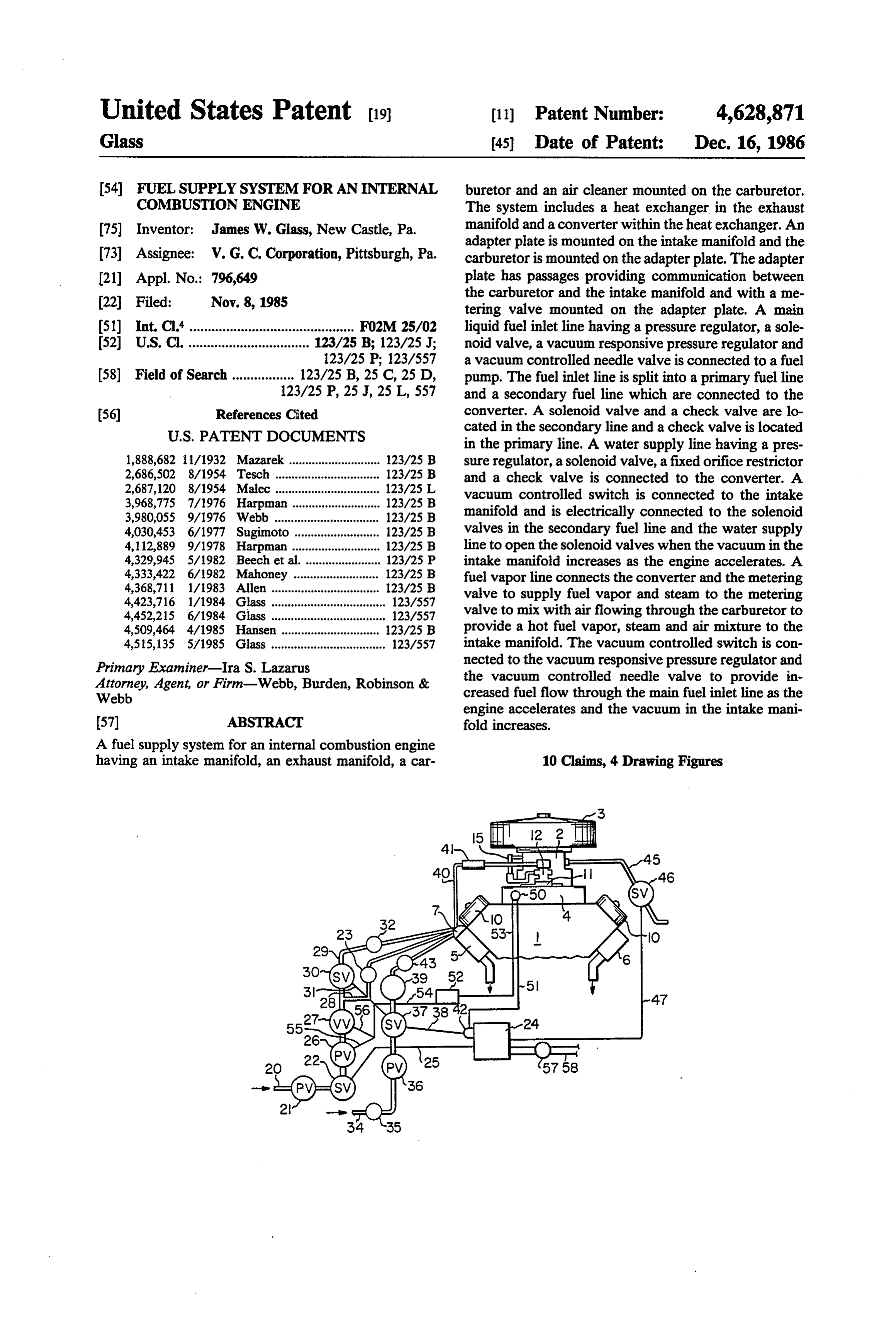
United States Patent (19) 11 Patent Number: 4,628,871 Glass 45 Date of Patent: Dec. 16, 1986 54 FUELSUPPLY SYSTEM FOR AN INTERNAL buretor and an air cleaner mounted on the carburetor. COMBUSTION ENGINE The system includes a heat exchanger in the exhaust 75) Inventor: James W. Glass, New Castle, Pa. manifold and a converter within the heat exchanger. An adapter plate is mounted on the intake manifold and the 73) Assignee: W. G. C. Corporation, Pittsburgh, Pa. carburetor is mounted on the adapter plate. The adapter (21) Appl. No.: 796,649 plate has passages providing communication between the carburetor and the intake manifold and with a me 22 Filed: Nov. 8, 1985 tering valve mounted on the adapter plate. A main 51) Int. Cl'............................................. F02M 25/02 liquid fuel inlet line having a pressure regulator, a sole 52) U.S. C. ................................. 123/25 B; 123/25 J; noid valve, a vacuum responsive pressure regulator and 123/25 P; 123/557 a vacuum controlled needle valve is connected to a fuel 58) Field of Search ................. 123/25 B, 25C, 25 D, pump. The fuel inlet line is split into a primary fuel line 123/25 P, 25 J, 25 L, 557 and a secondary fuel line which are connected to the 56) References Cited converter. A solenoid valve and a check valve are lo
in the primary line. A water supply line having a pres 1,888,682 11/1932 Mazarek .... ... 23/2SB sure regulator, a solenoid valve, a fixed orifice restrictor 2,686,502 8/1954 Tesch ... ... 123/25B and a check valve is connected to the converter. A 2,687,120 8/1954 Malec .... ... 123/2.5 L vacuum controlled switch is connected to the intake 3,968,775 7/1976 Harpman ... 123/25 B manifold and is electrically connected to the solenoid 3,980,055 9/1976 Webb ......... ... 123/25 B 4,030,453 6/1977 Sugimoto. ... 123/25 B valves in the secondary fuel line and the water supply 4,112,889 9/1978 Harpman ....... ... 123/25 B line to open the solenoid valves when the vacuum in the 4,329,945 5/1982 Beech et al. ... ... 123/25 P intake manifold increases as the engine accelerates. A 4,333,422 6/1982 Mahoney ....... ... 123/2SB fuel vapor line connects the converter and the metering 4,368,711 1/1983 Allen ..... ... i23/25B valve to supply fuel vapor and steam to the metering 4,423,716 1/1984 Glass ................................... 123/557 valve to mix with air flowing through the carburetor to 4,452,215 6/1984 Glass ................................... 123/557 4,509,464 4/1985 Hansen. 123/25 B provide a hot fuel vapor, steam and air mixture to the 4,515,135 5/1985 Glass ..... - -- 123/557 intake manifold. The vacuum controlled switch is con Primary Examiner-Ira S. Lazarus nected to the vacuum responsive pressure regulator and Attorney, Agent, or Firm-Webb, Burden, Robinson & the vacuum controlled needle valve to provide in Webb creased fuel flow through the main fuel inlet line as the engine accelerates and the vacuum in the intake mani 57 ABSTRACT fold increases.
A fuel supply system for an internal combustion engine having an intake manifold, an exhaust manifold, a car 10 Claims, 4 Drawing Figures
Page 2
Drawing sheet — no readable text.
Page 3
Drawing sheet — no readable text.
Page 4
cleaner are mounted on the adapter plate to supply
FUEL SUPPLY SYSTEM FOR AN INTERNAL combustion air to the intake manifold.
COMBUSTON ENGINE
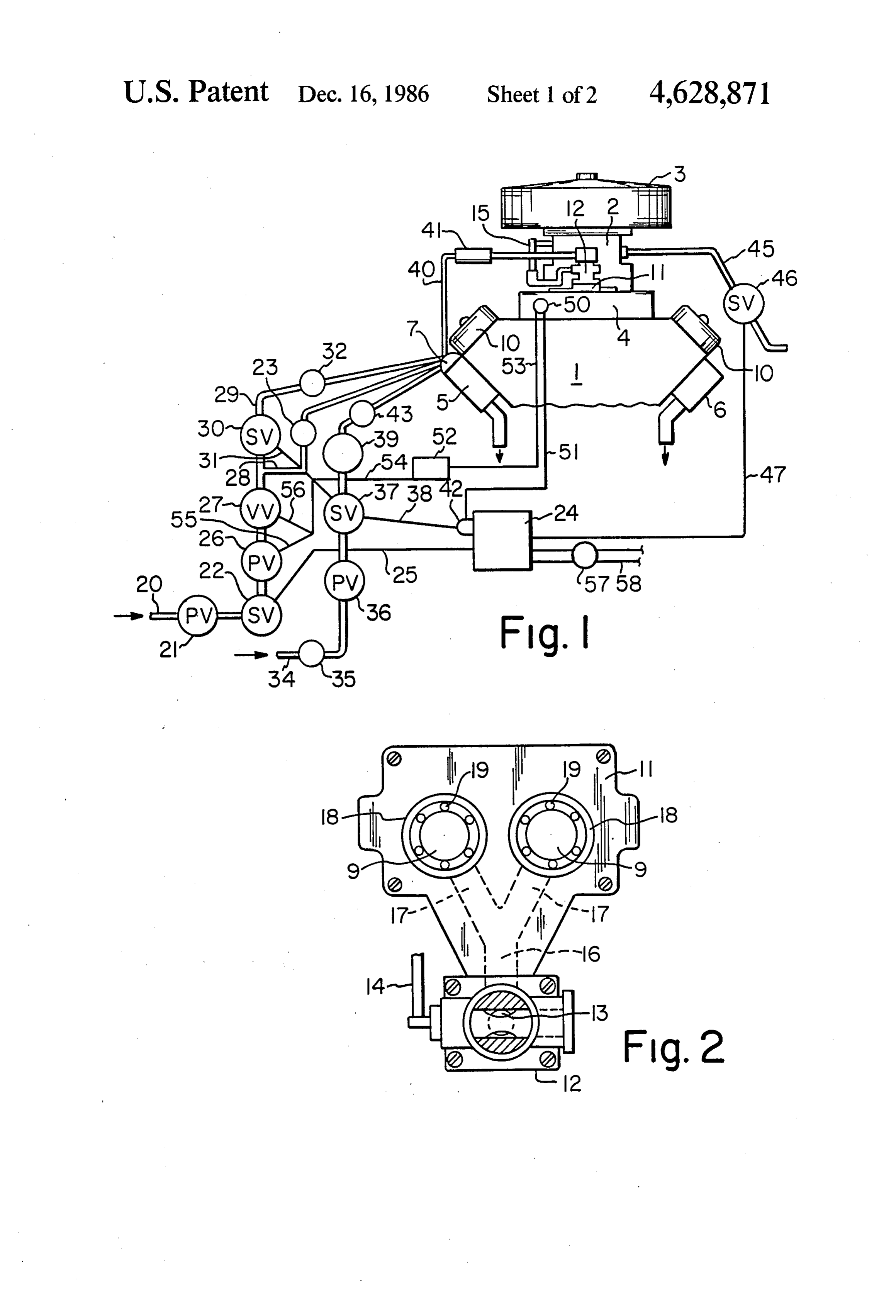
DESCRIPTION OF THE DRAWINGS
BACKGROUND OF THE INVENTION 5 FIG. 1 is a diagrammatic illustration of an internal 1. Field of the Invention combustion engine, and the fuel supply system of the The invention relates generally to a fuel supply sys invention;
tem for use with an internal combustion engine and mounted FIG. 2 is a plan view of the adapter plate and valve more particularly to a fuel supply system wherein a O FIG. 3onis the a engine in the fuel system;
side elevation of the adapter plate and heated mixture of air, gasoline vapor and, under certain conditions, steam are provided to the intake manifold of valve shown in FIG. 2; and
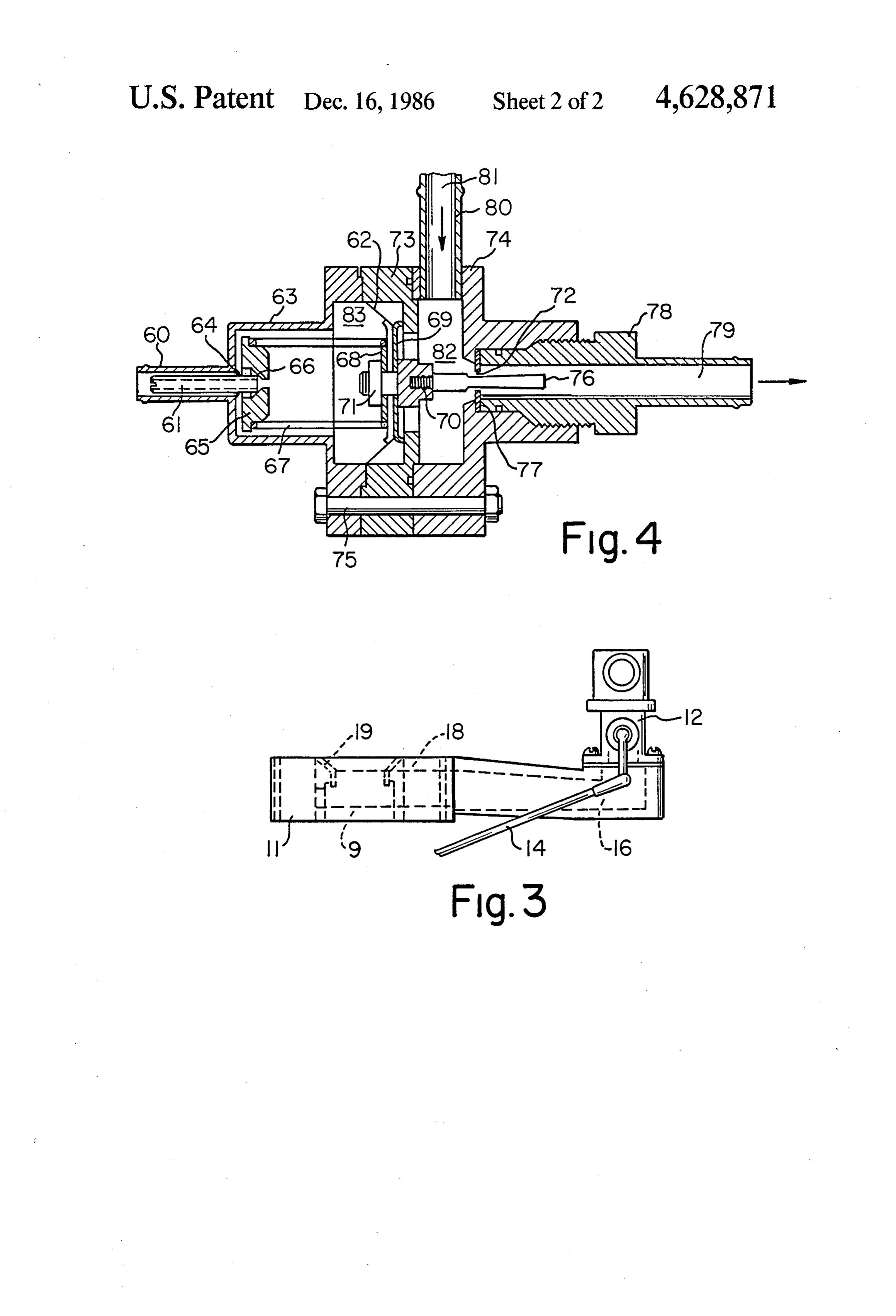
FIG. 4 is a section through the vacuum controlled the engine to increase the efficiency of the engine and to needle valve used in the main liquid gasoline line of the decrease the pollutants exhausted from the engine. fuel system.
2. Description of the Prior Art
A fuel supply system for an internal combustion en 15 DESCRIPTION OF THE PREFERRED gine generally includes at least one carburetor wherein EMBODIMENT liquid gasoline is sprayed into a stream of incoming air FIG. 1 of the drawings shows the fuel supply system which divides the liquid gasoline into fine droplets and in conjunction with a standard internal combustion conveys the gasoline droplets to the intake manifold of 20 engine 1 having a standard carburetor 2 mounted the engine. In such an arrangement, only the surface of thereon and a standard air cleaner 3 mounted on the the gasoline droplets can react with the oxygen in the carburetor. The internal combustion engine includes an air to burn which results in incomplete combustion and therefore does not fully utilize the fuel. Additionally, intake manifold 4, exhaust manifolds 5 and 6 and valve the exhaust gases discharged from the engine contain 25 covers 10. An adapter plate 11 and a mechanical meter ing valve 12, shown in detail in FIGS. 2 and 3 of the substantial amounts of unburned hydrocarbons, carbon drawings, are mounted on intake manifold 4 and are in monoxide and oxides of nitrogen which are undesirable communication therewith. The carburetor 2 is mounted air pollutants.
Improved fuel supply systems include fuel injection on the top of adapter plate 11 and is in communication with the intake manifold through openings 9 in the arrangements wherein liquid fuel is injected directly 30 adapter plate.
into the intake manifold of an engine. Such systems The carburetor 2 contains a butterfly valve (not provide greater vaporization than systems using one or shown) for controlling the flow of combustion air to more carburetors, but the fuel is still not completely and intake manifold 4 and has an accelerator control link 15 efficiently burned. for operating the butterfly valve. The mechanical me Other fuel supply systems introduce water into liquid tering valve 12 is also mounted on adapter plate 11 and fuel and attempts have been made to simultaneously is illustrated in FIGS. 2 and 3 of the drawings. The vaporize the liquid fuel and the water. Such systems are metering valve 12 controls the flow through an inlet relatively ineffective because of the separation of the port 13 into a passage 16 in the adapter plate. An accel liquid fuel vapor and the steam into droplets which erator link 14 is attached to metering valve 12 for con results in incomplete combustion of the fuel mixture and trolling flow through the valve to inlet port 13. The occasional stalling of the engine. Additionally, this type links 14 and 15 normally urge the butterfly valve in of system requires that the engine operate at substan carburetor 2 and mechanical metering valve 12 into an tially uniform rpm or at a steady number of miles per almost closed position wherein air and fuel flowing to hour. the engine intake manifold are sufficient only for idling. Systems for producing a gaseous fuel for use in an 45 The operation of the accelerator moves links 14 and 15 internal combustion engine are disclosed in U.S. Pats. to simultaneously control both the butterfly valve in Nos. 4,452,215 and 4,423,716 which are directed to carburetor 2 and the mechanical metering valve 12 on inventions made by the inventor of the instant applica adapter plate 11.
tion. The invention of the instant application is an im With specific reference to FIG. 1 of the drawings, the provement over the systems disclosed in those patents. 50 fuel supply system comprises a main liquid fuel inlet line SUMMARY OF THE INVENTION 20 having its inlet end connected to a standard fuel pump (not shown). The inlet end of fuel line 20 has a
A fuel supply system for an internal combustion en preset pressure regulator 21 located therein. The pres gine wherein liquid gasoline is supplied to a converter in sure regulator is manufactured by C. R. Industries in a heat exchanger to produce heated fuel vapor under 55 Elgin, Ill. Downstream of pressure regulator 21, the fuel pressure which is supplied to the intake manifold of the line is connected to a solenoid valve 22 which is electri engine. The system includes a control valve and a pres cally connected to a standard delay relay 24 by conduc sure regulator in the main liquid fuel line which are tors 25. The fuel line also includes a vacuum responsive repsonsive to the intake manifold vacuum. Water may adjustable pressure regulator 26 downstream of sole also be supplied to the converter in the heat exchanger 60 noid valve 22 and a vacuum controlled needle valve 27 under certain conditions to be vaporized and supplied to downstream of pressure regulator 26. The needle valve the intake manifold of the engine along with the heated 27 is shown in detail in FIG. 4 of the drawings. At the gasoline vapor. The heat exchanger is an integral part of downstream side of needle valve 27, fuel line 20 is split the engine exhaust manifold so that the exhaust gas heat into a primary fuel line 28 flowing through a check is utilized to heat and vaporize the liquid gasoline and 65 valve 23 to a converter (not shown) in a heat exchanger the water. The fuel vapor and steam enter the engine 7 in exhaust manifold 5 and a secondary fuel line 29 intake manifold through a valve and an adapter plate flowing into the converter in heat exchanger 7 in ex having spray rings. A conventional carburetor and air haust manifold 5 through a solenoid valve 30 and a
Page 5
check valve 32. The converter and heat exchanger 7 are which varies as the engine speed varies. Thus, a rela constructed in accordance with U.S. Pat. No. 4,515,135 tively higher vacuum exists when the engine is operat except that they are located within the exhaust manifold ing at high speed, and this permits the controlled needle 5 rather than being piped to the exhaust manifold as in valve 27 to open to its maximum flow capacity to per the aforementioned patent. mit an increased amount of fuel to flow to the converter A water supply line 34 is connected at its inlet end to in heat exchanger 7. As the engine speed decreases, the a reservoir (not shown) containing water with alcohol vacuum in the intake manifold decreases, and control mixed therein to prevent freezing. A standard water valve 27 gradually closes to decrease the amount of fuel pump 35 pumps water from the reservoir through water flowing to the converter and subsequently to the intake supply line 34. The flow of water through line 34 is O manifold of the engine. The needle valve 27 is formed controlled by a preset pressure regulator 36 and a sole by an inlet body section 63, a center body section 73 and noid valve 37 which is electrically connected to delay an outlet body section 74. The vacuum chamber 83 is relay 24 by conductors 38. Solenoid valve 37 is also formed by body section 63 and center body section 73, electrically connected to solenoid valve 30 by conduc and the fuel chamber 82 is formed by outlet body sec tors 31. A switching terminal 42 for controlling the 15 tion 74 and center body section 73. The three sections of operation of solenoid valves 30 and 37 is located adja the valve body are held together by a plurality of bolts cent to delay relay 24. A fixed orifice restrictor 39 is 75. An outlet member 78 having a passage 79 formed included in water line 34 downstream of solenoid valve therein is threadedly connected at one end to body 37, and a check valve 43 is located between the con section 74 and is connected at the other end to the fuel verter in heat exchanger 7 in exhaust manifold 5 so that line 20. An inlet member 80 having a passage 81 is con water flows through the restrictor and the check valve nected at one end to fuel line 20 and at the other end to prior to entering the converter in the heat exchanger. body
The check valves 23, 32 and 43 prevent reverse flow passagesection 74 so that liquid fuel supplied through through the respective fuel and water lines, and the passes out throughinto 81 flows fuel chamber 82 in valve 27 and orifice 72 in the orifice plate 77 into pressure regulator insures that the water pressure is the 25 the passage 79 in outlet member 78 from which it flows same as the fuel pressure in line 20.
Vaporized fuel and steam, when used, flow from the S.to the converter in heat exchanger 7 in exhaust manifold converter in heat exchanger 7 through a vapor conduit The valve includes a vacuum tube 60 which is in 40 having insulation 4 therearound into the metering communication valve 12 from which the vaporized fuel and steam flow tube 60 containswith
branch 56 of vacuum line 54. The hollow adjustment member 61 which through inlet port 13 into the adapter plate 11. Vapor conduit 40 is insulated so that the heat loss from the fuel permits the vacuum in the intake manifold to act upon a vapor and steam is minimized between the converter in diaphragm27 and 62 located within the body of needle valve having its outer edge clamped between body heat exchanger 7 in exhaust manifold 5 and the inlet port 13 in metering valve 12. The heated fuel vapor and 35 sections 63 and 73. The diaphragm is made from a mate steam mixture flows through passage 16 and passages 17 rial which is resistant to both elevated temperatures and in adapter plate 11 to a pair of outlet rings 18. Each hydrocarbons. The adjustment member 61 is threadedly outlet ring has a plurality of spray nozzles 19 located the connected to inlet body section 63 by threads 64, and around its periphery. Fuel vapor and steam are sprayed inner end of member 61 contacts the recessed center from the spray nozzles 19 into the air passing through 40 portion 66 of a base member 65 located in the vacuum openings 9 from the air cleaner and the carburetor. chamber of the valve. Base member 65supports one end The engine has an auxiliary fuel line 45 which initially of a coil spring 67, and the opposite end of coil spring 67 supplies liquid fuel to carburetor 2 until the engine has contacts the periphery of a washer 68 which is in run for a short period of time to raise the temperature in contact with one side of diaphragm 62. The washer 68 heat exchanger 7 in exhaust manifold 5 to a temperature 45 is on the vacuum side of the diaphragm, and a compli sufficient to vaporize the fuel flowing to the converter mentary washer 69 is located on the opposite side of through primary fuel line 28. The auxiliary fuel line 45 diaphragm 62 in fuel chamber 82 of the valve. A bolt includes solenoid valve 46 which is electrically con extends through the center of the diaphragm and nected with delay relay 24 by conductors 47. through washers 68 and 69.
A vacuum controlled switch 50 is mounted near the 50 The bolt has an enlarged head 70 located in fuel intake manifold with a probe extending into the mani chamber 82 and a threaded end located in vacuum fold to sense the vacuum therein. The switch is a snap chamber 83 which receives a nut 71. When nut 71 is action type manufactured by Borg-Warner Corpora tightened on the bolt, the head 70 contacts washer 69 tion. The vacuum control switch 50 is electrically con and the nut contacts washer 68 to clamp the washers nected by conductors 51 to delay relay 24. The vacuum 55 and the diaphragm together. A tapered metering rod 76 control switch is also in flow communication with a is threadedly connected to a threaded bore in bolt head vacuum block 52 by means of a conduit 53. The vacuum 70. The metering rod passes through orifice 72 in orifice block is a hollow aluminum block having an inlet for plate 77 to form an annular passage between the orifice conduit 53 and an outlet which is connected to a con plate and the rod.
duit 54 having a first branch 55 connected to pressure 60 In operation the size of the annular passage in orifice regulator 26 and a second branch 56 connected to vac 72 in orifice plate 77 is controlled by the position of the uum controlled needle valve 27. tapered metering rod 76 which is controlled by the The vacuum controlled needle valve 27 is shown in position of diaphragm 62 in vacuum chamber 83. The detail in FIG. 4 of the drawings. The valve controls the vacuum in the intake manifold and the coil spring 67 flow of liquid fuel through fuel line 20 to the primary 65 move the diaphragm and the metering rod to control fuel line 28 and the secondary fuel line 29. Valve 27 is the amount of liquid fuel which can pass through the connected with the intake manifold of the engine and annular passage in orifice 72 in orifice plate 77 to the responds to the vacuum created in the intake manifold converter in the heat exchanger.
Page 6
The fuel system of the invention operates as follows. switching terimal 42 which is electrically connected to The ignition switch 57 is closed when the key is turned vacuum switch 50.
to the on position to activate the automobile electrical While a delay relay 24 is shown in FIG. 1 of the system and supply current through conductors 58 to drawings for controlling the solenoid valves, it will be delay relay 24. Delay relay 24 opens solenoid valve 46 understood by those skilled in the art that manual con in auxiliary fuel line 45 to provide liquid fuel from the trol switches may be utilized to control the fuel supply fuel pump to the carburetor 2 so that the engine can system in place of the delay relay. start. After the engine has run for a short period of time, The fuel supply system of the invention is balanced for example, approximately three minutes, the exhaust by preset pressure regulator 21 and vacuum responsive manifold will be heated to a sufficient temperature, O pressure regulator 26 so as to supply the amount of fuel approximately 1200 F., to vaporize liquid fuel passing necessary to obtain the proper idle when the fuel is in to the converter through primary fuel line 28. At this the vapor condition. As the vacuum in the intake mani point, a time delay switch in the delay relay closes sole fold increases during acceleration, the vacuum con noid valve 46 to eliminate the fuel line 45 from the fuel trolled needle valve 27 opens to permit a greater vol supply system. Whereas the auxiliary fuel line is used to 15 ume of liquid fuel to flow to the converter and pressure supply fuel to the engine until the temperature in the regulator 26 opens to permit flow at an increased pres exhaust manifold is sufficiently high to vaporize the sure which results in more fuel vapor flowing to the liquid fuel in the converter, it will be recognized by engine during acceleration. Additionally, switching those skilled in the art that a glow plug or other electric terminal 42 opens solenoid valves 30 and 37 at higher heat source may be utilized to initially vaporize the 20 engine speeds to increase the amount of liquid fuel flow liquid fuel flowing to the intake manifold and thereby ing to the converter and to permit water to flow to the eliminate the auxiliary fuel line. COveter.
When delay relay 24 closes solenoid valve 46, sole It will be seen that the invention provides a simple yet noid valve 22 in the fuel line 20 is opened to permit very efficient fuel supply system for an internal combus liquid fuel to flow through the primary fuel line 28 to 25 tion engine. Liquid fuel is efficiently and rapidly con the converter in the heat exchanger 7 in exhaust mani verted to vapor at an optimum temperature within only fold 5 to vaporize the fuel and supply it to the engine a few minutes of initial engine start-up. The system intake manifold through vapor conduit 40, metering continuously delivers a mixture of heated vaporized valve 12 and adapter plate 11. The liquid fuel will va fuel and air to the intake manifold in the amount re porize at approximately 1200' F. in the converter lo 30 quired for normal operation of an internal combustion cated in the heat exchanger and, as stated, this tempera engine. Additionally, the system permits the addition of ture will be reached after approximately three minutes steam to the mixture at accelerated engine speeds which of engine operation. The vacuum controlled needle further decreases fuel consumption and reduces carbon valve 27 in fuel line 20 operates after the fuel supply buildup in the engine. Because the fuel is in the vapor system is switched from initial carburetor operation to 35 ized condition, more complete combustion thereof oc vapor operation. The vacuum pulled in the valve will curs, and the pollutants in the engine exhaust gases are vary from 8 to 10 inches of mercury, and the valve will decreased to the extent that the engine can be operated open as the vacuum in the intake manifold increases at without a catalytic converter in the exhaust system and higher speeds. The valve closes as the vacuum in the emit exhaust gases well within the federal regulations intake manifold decreases as the engine speed slows to for air pollution. Additionally, the improved fuel supply idle speed. system of the invention provides a substantial increase The preset pressure regulator 21 in the fuel line 20 is in the miles driven per gallon of fuel when compared permanently set at 2.5 pounds per square inch maximum with the miles per gallon obtained with the engine oper pressure to lower the pressure of the fuel which is sup ating on a normal carburetion system. plied from the vehicle fuel tank by the fuel pump which 45 While a preferred embodiment of the invention has is normally on the order of 7 pounds per square inch. been described herein, it is to be understood that it may The adjustable pressure regulator 26 in fuel line 20 is be embodied within the scope of the appended claims. controlled by the vacuum in the intake manifold and I claim:
will begin to operate at approximately one pound per 1. A fuel supply system for an internal combustion square inch, and as the engine speed increases and the 50 engine having an intake manifold, an exhaust manifold vacuum increases, the pressure regulator 26 will open to and a carburetor in communication with said intake a maximum of 2.5 pounds per square inch. manifold, said system including heat exchange means in The solenoid valve 30 in the secondary fuel line 29 said exhaust manifold, an adapter plate mounted on said will be opened when the engine speed increases suffi intake manifold and supporting said carburetor, means ciently for the vacuum in intake manifold 4 to drop 55 in said adapter plate providing flow communication below 8-10 inches of mercury to permit additional fuel between said carburetor and said intake manifold, a to flow to the converter in heat exchanger 7 and to metering valve mounted on said adapter plate and con intake manifold 4 at higher engine speeds. Additionally, necting means in said adapter plate connecting said the solenoid valve 37 in the water line 34 will open metering valve and said means providing flow commu when the vacuum in the intake manifold drops below 60 nication between said carburetor and said intake mani approximately 8-10 inches of mercury. This insures that fold, a main liquid fuel line having an inlet end adapted no water will flow into the engine intake manifold since to be connected to a fuel pump, a pressure regulator in the vacuum will not drop below 8-10 inches of mercury said fuel line, a solenoid valve in said fuel line down until the engine has accelerated, at which point the stream of said pressure regulator, a vacuum responsive converter in heat exchanger 7 is at a sufficiently high 65 pressure regulator in said fuel line downstream of said temperature to guarantee that all of the water will be solenoid valve and a vacuum controlled needle valve in vaporized before it is supplied to the intake manifold. said fuel line downstream of said vacuum responsive Solenoid valves 30 and 37 are operated by a standard pressure regulator, said main fuel line being split into a
Page 7
primary line and a secondary line downstream of said needle valve includes a vacuum block having an inlet vacuum controlled needle valve, a solenoid valve in end connected to said vacuum controlled switch and an said secondary line, said primary line and said second outlet end connected to said vacuum responsive pres ary line extending to said heat exchange means to sup sure regulator and said vacuum controlled needle valve. ply liquid fuel to said heat exchange means to vaporize 7. A fuel supply system as set forth in claim 1 includ the liquid fuel, a water line adapted to be connected to ing an electric water pump in said water supply line a pump, a pressure regulator in said water line, a sole upstream of said pressure regulator. noid valve in said water line downstream of said pres 8. A fuel supply system as set forth in claim 1 wherein sure regulator and a fixed orifice restrictor in said water said connecting means in said adapter plate is a pair of line downstream of said solenoid valve, said water line O bores extending through said adapter plate between said extending between said fixed orifice restrictor and said carburetor and said intake manifold and a plurality of heat exchange means to supply water to said heat ex spaced spray nozzles in said adapter plate located at the change means, a vacuum controlled switch in communi periphery of each bore.
cation with said intake manifold, means electrically 9. A fuel supply system as set forth in claim 1 wherein connecting said vacuum controlled switch with said 15 said vacuum controlled needle valve includes a hollow solenoid valves in said secondary line and said water casing having a liquid fuel inlet member and a liquid fuel line and means providing a pressure connection be outlet member, a diaphragm in said casing dividing the tween said vacuum controlled switch and said vacuum interior of said casing into a vacuum chamber and a responsive pressure regulator and said vacuum con liquid fuel chamber, means connecting said vacuum trolled needle valve wherein said solenoid valves are 20 chamber with said means providing a pressure connec opened when said vacuum in said intake manifold in tion with said vacuum controlled switch and means creases as said engine accelerates to permit additional connecting said liquid fuel outlet member to said heat liquid fuel and water to flow to said heat exchange exchange means, resilient means in said vacuum cham means to be converted to hot fuel vapor and steam, a ber to position said diaphragm, means forming a fuel fuel vapor line connecting said heat exchange means 25 outlet orifice in said liquid fuel chamber providing a and said metering valve whereby hot fuel vapor and connection between said liquid fuel chamber and said steam flows through said fuel vapor line to said meter liquid fuel outlet member and a taperd metering rod ing valve and through said connecting means in said attached to said diaphragm and extending through said adapter plate to mix with air flowing from said carbure orifice, whereby the position of said metering rod rela tor to said means in said adapter plate providing flow 30 tive to said orifice member is adjusted by movement of communication between said carburetor and said intake said diaphragm in response to the vacuum in said intake manifold, whereby a heated fuel vapor, steam and air manifold to control the amount of fuel which can flow mixture is provided to said intake manifold for combus through said orifice to said heat exchange means. tion in the internal combustion engine. 10. A fuel supply system for an internal combustion 2. A fuel supply system as set forth in claim 1 wherein 35 engine having an intake manifold, an exhaust manifold said connecting means in said adapter plate is at least and a carburetor in communication with said intake one bore extending through said adapter plate between manifold, said system including heat exchange means in said carburetor and said intake manifold and a plurality said exhaust manifold, an adapter plate mounted on said of spaced spray nozzles in said adapter plate located at intake manifold and supporting said carburetor, con the periphery of said bore, whereby a mixture of hot necting means in said adapter plate providing flow com fuel vapor and steam are sprayed from said nozzles into munication between said carburetor and said intake air passing through said bore. manifold, a metering valve mounted on said adapter 3. A fuel supply system as set forth in claim 1 includ plate and means in said adapter plate connecting said ing an auxiliary liquid fuel line adapted to be connected metering valve and said connecting means, a main liquid to a fuel pump, a solenoid valve in said auxiliary fuel 45 fuel line adapted to be connected to a fuel pump, a line and a delay relay electrically connected to said pressure regulator at the inlet end of said line, a solenoid solenoid valve in said auxiliary fuel line whereby liquid valve in said line downstream of said pressure regulator, fuel is initially provided to said carburetor through said a vacuum responsive pressure regulator in said line auxiliary fuel line until said delay relay closes said sole downstream of said solenoid valve and a vacuum con noid valve in said auxiliary fuel line after a preset time 50 trolled needle valve in said line downstream of said to remove said auxiliary fuel line from the fuel supply vacuum responsive pressure regulator, said main fuel system and opens said solenoid valve in said main fuel line being split into a primary line and a secondary line line to permit liquid fuel to flow to said heat exchange downstream from said vacuum controlled needle valve, means for conversion to vapor. a solenoid valve in said secondary line, said primary line 4. A fuel supply system as set forth in claim 1 wherein 55 and said secondary line being connected to said heat said means electrically connecting said vacuum con exchange means to supply liquid fuel to said heat ex trolled switch with said solenoid valves in said second change means to be vaporized, a water line adapted to ary line and said water line includes a switching termi be connected to a reservoir, a pressure regulator at the nal to open said solenoid valve in said water line and inlet end of said water line, a solenoid valve in said said solenoid valve in said secondary line. water line downstream of said pressure regulator and a 5. A fuel supply system as set forth in claim 1 includ fixed orifice restrictor in said water line downstream of ing a check valve in each of said primary and secondary said solenoid valve, a conduit between said fixed orifice lines and said water line, said check valves being lo member and said heat exchange means to supply water cated upstream of said heat exchange means. to said heat exchange means to be vaporized, means 6. A fuel supply system as set forth in claim 1 wherein 65 responsive to a vacuum in communication with said said means providing a pressure connection between intake manifold and electrically connected to said sole said vacuum controlled switch and said vacuum respon noid valves in said secondary line and said water line sive pressure regulator and said vacuum controlled and in pressure communication with said vacuum re
Page 8
sponsive pressure regulator and said vacuum controlled and water is converted to steam in said heat exchange needle valve wherein said solenoid valves in said sec means which flow through said fuel vapor line to said ondary line and said water line are opened when said metering valve and through said connecting means in vacuum in said intake manifold increases as said engine said adapter plate to mix with air flowing from said air accelerates to permit additional liquid fuel and water to cleaner through said carburetor to provide a hot fuel flow to said heat exchange means, a fuel vapor line vapor, steam and air mixture to said intake manifold for connecting said heat exchange means and said metering combustion in the internal combustion engine. valve whereby liquid fuel is converted to hot fuel vapol
Provenance
- Collection
- Cited prior art
- Original PDF
- patentimages.storage.googleapis.com →
- Filed
- 1985-11-08
- Pages
- 8
- Method
- pdftotext (the PDF's own text layer) + pdftoppm 300dpi page scans
- Source
- Google Patents bibliographic record
- Granted
- 1986-12-16
- Inventors
- James W. Glass; V G C CORP
- Transcribed from
- patentimages.storage.googleapis.com →