patent · US4178882
Hydrogen fuel supply system
18 December 1979
Page 1 — bibliographic record
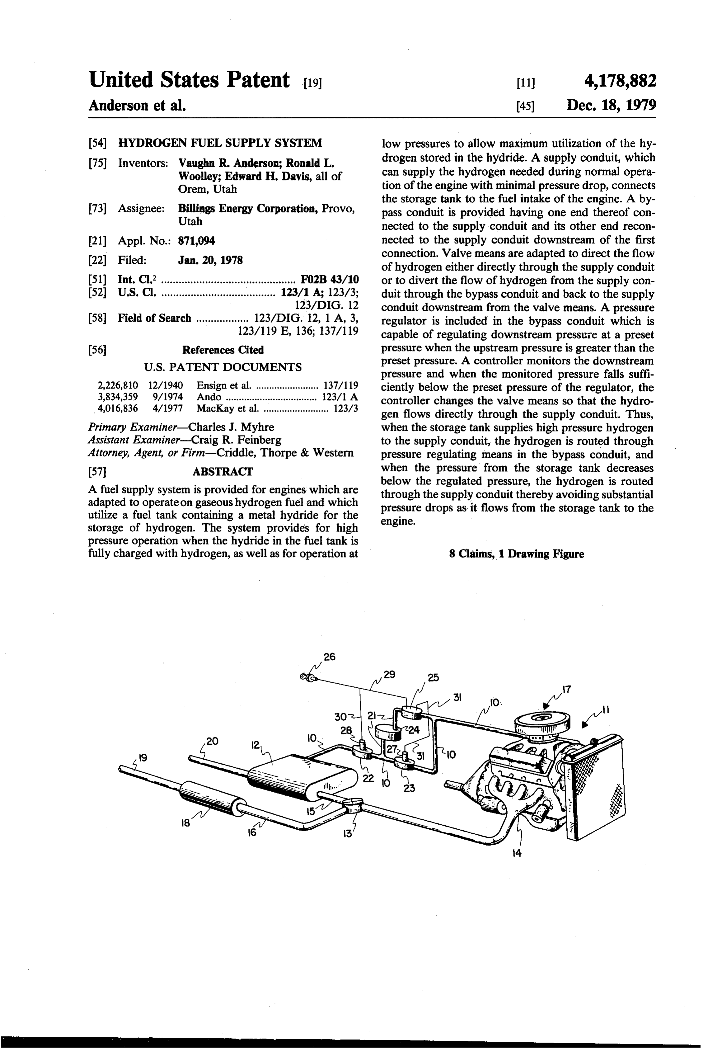
United States Patent (19) 11) 4,178,882 Anderson et al. 45) Dec. 18, 1979 54 HYDROGENFUEL SUPPLY SYSTEM low pressures to allow maximum utilization of the hy (75 Inventors: Vaughn R. Anderson; Ronald L. drogen stored in the hydride. A supply conduit, which Woolley; Edward H. Davis, all of can supply the hydrogen needed during normal opera Orem, Utah tion of the engine with minimal pressure drop, connects the storage tank to the fuel intake of the engine. A by 73 Assignee: Billings Energy Corporation, Provo, pass conduit is provided having one end thereof con Utah nected to the supply conduit and its other end recon (21) Appl. No.: 871,094 nected to the supply conduit downstream of the first 22 Filed: Jan. 20, 1978 connection. Valve means are adapted to direct the flow of hydrogen either directly through the supply conduit 51) Int. C.’.............................................. F02B 43/10 or to divert the flow of hydrogen from the supply con 52 U.S. Cl. ....................................... 123/1 A; 123/3; duit through the bypass conduit and back to the supply 123/DIG. 12 conduit downstream from the valve means. A pressure 58 Field of Search .................. 123/DIG. 12, 1 A, 3, regulator is included in the bypass conduit which is 123/119 E, 136; 137/119 capable of regulating downstream pressure at a preset 56 References Cited pressure when the upstream pressure is greater than the
pressure and when the monitored pressure falls suffi 2,226,810 12/1940 Ensign et al. ........................ 137/119 ciently below the preset pressure of the regulator, the 3,834,359 9/1974 Ando ............... ... 123/1 A controller changes the valve means so that the hydro 4,016,836 4/1977 MacKay et al. ......................... 123/3 gen flows directly through the supply conduit. Thus, Primary Examiner-Charles J. Myhre when the storage tank supplies high pressure hydrogen Assistant Examiner-Craig R. Feinberg to the supply conduit, the hydrogen is routed through Attorney, Agent, or Firm-Criddle, Thorpe & Western pressure regulating means in the bypass conduit, and 57 ABSTRACT when the pressure from the storage tank decreases A fuel supply system is provided for engines which are below the regulated pressure, the hydrogen is routed adapted to operate on gaseous hydrogen fuel and which through the supply conduit thereby avoiding substantial utilize a fuel tank containing a metal hydride for the pressure drops as it flows from the storage tank to the storage of hydrogen. The system provides for high engine.
pressure operation when the hydride in the fuel tank is fully charged with hydrogen, as well as for operation at 8 Claims, 1 Drawing Figure
Page 2
Drawing sheet — no readable text.
Page 3
means for feeding gaseous hydrogen to the intake mani
HYDROGEN FUEL SUPPLY SYSTEM fold thereof, a fuel tank containing a metal hydride which is capable of reacting with and absorbing hydro
BACKGROUND OF THE INVENTION gen at a given temperature and pressure, and of releas 1. Field ing hydrogen gas at a temperature higher than the given The invention relates to internal combustion engines temperature and/or a pressure lower than the given which are designed to operate on gaseous hydrogen fuel pressure. A supply conduit is connected between the and which utilize a fuel tank containing a metal hydride fuel tank and the feed means to the intake manifold of for the storage of hydrogen. In particular, the invention the engine for flow of gaseous hydrogen from the fuel relates to a fuel system for conveying the fuel from the 10 tank to the feed means. A bypass conduit has one end storage tanks to the engine. connected to the supply conduit at some point between 2. State of the Art the tank and the feed means, with the other end of the Internal combustion engines utilizing hydrogen fuel bypass conduit being reconnected to the supply conduit have been shown to be both feasible and an attractive downstream from the first connection. A pressure regu alternative to engines which utilize gasoline. See, for 15 lator is provided in conjunction with the bypass con example, U.S. Pat. No. 3,983,882 issued on Oct. 5, 1976 duit. The pressure regulator is adapted to regulate the to Roger E. Billings, as well as the references cited pressure downstream thereof at a preset value when the therein. The storage of hydrogen for use in internal upstream pressure is greater than the preset value, and combustion engines has presented difficult problems. 20 of allowing the downstream pressure to decrease below However, the use of storage containers containing the preset value when the upstream pressure is below metal hydrides has mitigated many of those problems. the preset value.
See, for example, U.S. Pat. No. 4,016,836 issued on Apr. Valve means are provided in combination with the 12, 1977 to Donald B. MacKay et al. supply conduit and the bypass conduit. The valve The hydride-containing containers are typically means are charged with hydrogen at a pressure of about 500 psig gas directlyadapted 25 to either direct the flow of hydrogen or greater. This pressure must be regulated when the flow of hydrogen gasthe through supply conduit or to divert the from the supply conduit through stored hydrogen is fed to the mixing device on the the bypass conduit and back to the supply conduit engine which mixes the hydrogen with air and intro downstream from the valve means. During the majority duces the mixture to the intake manifold of the engine. of an operation cycle of a fully charged storage tank, Regulators have been used in prior hydrogen fuel sys hydrogen is discharged
from the tank at relatively high tems, wherein the regulator regulates the hydrogen pressures, i.e., from about 150 to 500 psig. During this pressure downstream therefrom at a present pressure.
As the hydrogen is used from the hydride-containing period, the valve means are controlled so as to divert storage tanks, the pressure of the hydrogen released by the flow of hydrogen through the bypass conduit and the hydride is continuously reduced. At a point wherein 35 the pressure regulator which regulates the downstream the pressure of the hydrogen coming from the storage pressure of the hydrogen to a value no greater than can tanks is less than the preset pressure at which the regula adequately be handled by the downstream apparatus, tor is set, the regulator becomes ineffective, and the principally the feed means which introduces the hydro pressure downstream therefrom is the pressure of the gen to the intake manifold of the engine. When the hydrogen coming from the storage tanks less the pres upstream pressure, i.e., the pressure of the hydrogen sure drop incurred in passing through the flow conduits coming from the storage tank, declines to a level which and the pressure regulator. Because of the relatively is inadequate to supply a full flow of hydrogen because large pressure drop incurred, the hydride-storage tanks of the pressure drop through the bypass conduit and required recharging when the pressure therein fell to pressure regulator, the valve means are controlled so as about 100 to 150 psig. Considerable hydrogen is still 45 to direct the flow of hydrogen gas directly through the contained in the storage tanks at that pressure but is low-pressure-drop supply conduit and thus avoid the unavailable because of the pressure drop incurred in bypass conduit and its associated high pressure drop delivering the hydrogen to the engine. requirements. By avoiding the high pressure drop, an 3. Objective: adequate flow of hydrogen can be supplied to the en The principal objective of the present invention was 50 gine even when the pressure of the hydrogen coming to provide a hydrogen fuel supply system in which from the storage tank has declined to around 5 psig. nearly all the hydrogen stored in the storage tank before A pressure actuated controller is adapted to monitor the tank has to be recharged. the pressure of the hydrogen in the bypass conduit or SUMMARY OF THE INVENTION supply conduit downstream from the regulator and 55 controls the valve means in accordance with the moni
The foregoing objective was achieved in accordance tored pressure. The pressure at which the controller with this invention by providing a hydrogen fuel supply charges the valve means for flow of hydrogen directly system which is effective in delivering sufficient hydro through the supply conduit and avoid the bypass con gen to the engine to permit normal operation thereof duit can be set at any preset level which is no greater with storage tank pressures as low as about 5 psig by 60 than the preset pressure of the regulator but still large minimizing the pressure drop incurred in transferring enough that full flow of hydrogen can be delivered the hydrogen from the storage tank to the feed means through the bypass conduit at that pressure. It has been for feeding gaseous hydrogen to the intake manifold of found advantageous to set the control pressure of the the engine, i.e., the mixing device which mixes the hy controller at between about 50 to 100 psig. drogen with air and introduces the mixture to the intake 65 Preferably, means are also provided in combination manifold. with the controller whereby the valve means can be The fuel system of this invention comprises, in combi closed thereby preventing hydrogen gas flow through nation with an internal combustion engine having feed either the supply conduit or bypass conduit. This per
Page 4
mits charging of the storage tanks at high pressure with direct the flow of hydrogen gas directly through the out subjecting the downstream supply conduit, the by supply conduit 10 or to divert the flow of hydrogen gas pass conduit, and the feed means on the engine to such from the supply conduit 0 through the bypass conduit high pressure. 2 and back to the supply conduit 10 downstream from THE DRAWING the valve means. As shown in the drawing, the valve means comprises first and second valves 22 and 23 in
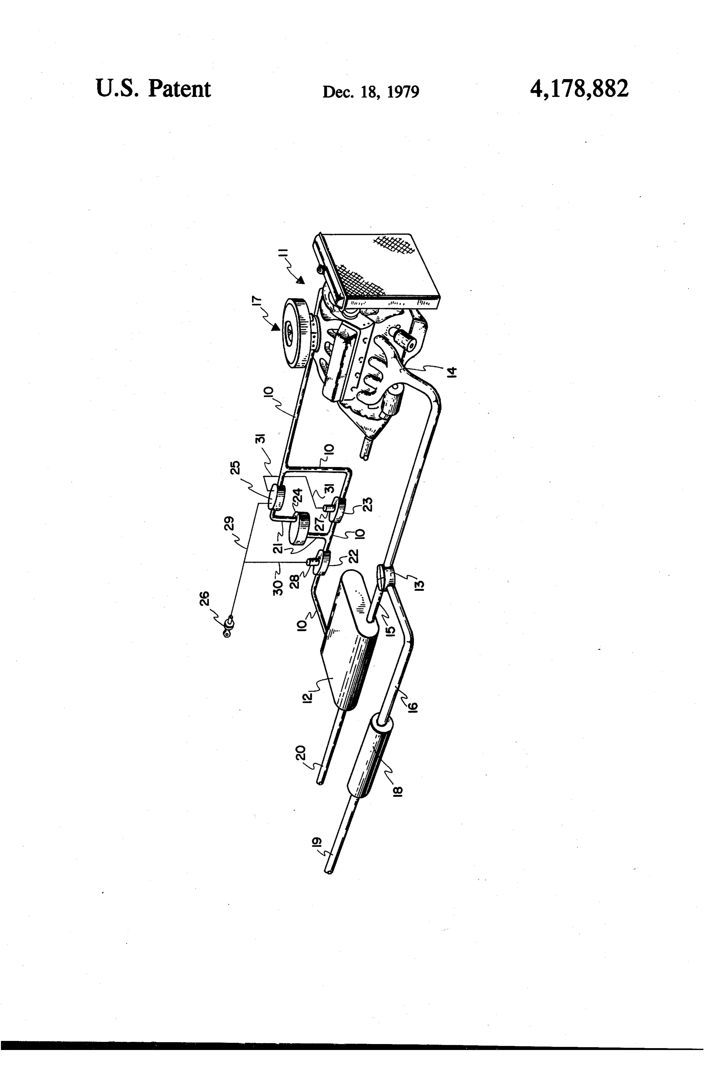
A particular embodiment of the present invention spaced relationship, with the first valve 22 being up representing the best mode presently contemplated of stream from the first connection of the bypass conduit carrying out the invention is illustrated in the accompa 21, and the second valve is located in the portion of the nying drawing consisting of a single figure showing a 10 supply conduit 10 between the connections of the by hydrogen fuel supply system for use with an internal pass conduit 21. When valve 23 is closed and valve 22 is combustion engine of a motor vehicle. open, the flow of hydrogen is directed through the DETAILED DESCRIPTION OF THE bypass conduit 21. When both valves 22 and 23 are ILLUSTRATED EMBODIMENT open, the flow of hydrogen is directed through conduit 15 10 directly to the carburetor 17.
In accordance with the present invention, a hydrogen A pressure regulator 24 is provided in combination supply system is provided in combination with an inter with bypass conduit 21 and is capable of regulating the nal combustion engine. In the drawing, an engine 11 of pressure downstream thereof at a preset value when the a motor vehicle is shown. A fuel supply conduit 10 pressure upstream thereof is greater than the preset connects the storage tank 12 with a carburetor 17 which 20 value, and of allowing the downstream pressure to de is adapted to receive gaseous hydrogen from the con crease below the preset value when the pressure up duit 10 and to mix the hydrogen gas with air for intro stream is below the preset value. Thus, when hydrogen duction to the intake manifold of the engine 11. Exem is obtained from the storage tank 12 at pressures above plary carburetors suitable for use with internal combus the preset value, say 150 psig, the regulator maintains a tion engines are disclosed in U.S. Pat. No. 3,983,882, 25 pressure of 150 psig, the preset value, in the down issued to Roger. E. Billings on Oct. 5, 1976. stream portion of conduits 2 and 10. As the pressure of The storage tank 12 contains a metal material which the hydrogen coming from tank 12 drops to less than is capable of reacting with and absorbing hydrogen at a 150 psig, the regulator 24 allows hydrogen flow there given temperature and pressure in the form of a metal through with a downstream pressure considerably less hydride, and the metal hydride is capable of dissociating 30 than the preset value or of the upstream pressure. and thereby releasing hydrogen when by raising the A pressure actuated controller is adapted to monitor temperature above the given temperature at which the the pressure downstream of the regulator 24 and to hydrogen was absorbed and/or reducing the given control the operation of the valve means and thereby pressure at which the hydrogen was absorbed. Exem the direction of flow of hydrogen through the system. plary metal materials which can be utilized include iron, 35 As illustrated, the controller 25 is positioned in the titanium, nickel, calcium, magnesium, manganese, rare downstream portion of bypass conduit 21 prior to the earth elements, and mixtures and alloys thereof. Alloys reconnection of that conduit with the supply conduit which are particularly advantageous include iron 10. The controller 25 is supplied with a source of elec titanium, lanthanum-nickel, calcium-nickel, mischmet trical current, such as from a remote switch 26. The al-nickel, manganese-nickel, and mischmetal-calcium switch 26 is advantageously the ignition switch for the nickel alloys. The storage tank 12 is adapted to hold the engine and is adapted to supply an electrical current to metal material therein and to enable the circulation of a controller 25 when the ignition switch is in any position heat exchange medium in proximity with the metal except the off position. The controller 25 is advanta material. Exemplary storage tank configurations are geously a pressure activated switch which is closed at a shown in U.S. Pat. No. 4,016,836, issued to Donald B. 45 selected pressure which is less than the preset value of MacKay et al. on Apr. 12, 1977. As shown in the draw regulator 24. The selected pressure for controller 25 can ing the exhaust manifold 14 is coupled by way of a be in the range of from about 20 to 100 psig, preferably bidirectional valve 13 to a conduit 15 to the tank 12, and from about 50 to 100 psig. When the switch of control to an exhaust pipe 16 leading to a muffler 18 and another ler 25 closes, electrical current is provided to a solenoid section of exhaust pipe 19. The valve 13 is adapted to 50 27 on valve 23. When the solenoid 27 is energized, it direct exhaust gases from the manifold 14 either opens valve 23. Otherwise, valve 23 is adapted to close through conduit 15 to the storage tank 12, or to pipe 16 automatically under spring force whenever the solenoid for discharge into the atmosphere, or to both. The ex 27 is not energized. Thus, when the pressure down haust gases introduced into tank 12 through conduit 15 stream of controller 25 is above the set pressure thereof, are exhausted therefrom through pipe 20. The operation 55 no current is supplied to solenoid 27 and valve 23 re of valve 13 and the exhaust system are fully described in mains closed, so that hydrogen gas is directed through the above-mentioned MacKay et al. Patent. bypass conduit 21. But, when the downstream pressure The hydrogen supply conduit 10 provides direct flow falls below the set pressure of controller 25, an electrical of gaseous hydrogen from tank 12 to carburetor 7 current is supplied to solenoid 27 and valve 23 opens, so during certain stages of the operation of tank 12 as will 60 that hydrogen gas can pass directly through conduit 10 be explained further hereinbelow. A bypass conduit 21 to carburetor 17. The pressure drop through conduit 10 is connected at one of its ends (the upstream end) to the is designed to be minimal and significantly less than the supply conduit 10 at a point between the tank 12 and pressure drop incurred through the regulator 24. Thus, carburetor 17, with its other end (downstream end) by avoiding the higher pressure drops associated with a reconnected to the supply conduit 10 downstream from 65 system containing a pressure regulator, a significantly the first connection. larger amount of hydrogen can be withdrawn from the Valve means are provided in combination with sup storage tank 12 in sufficient amount to operate the en ply conduit 10 and bypass conduit 21 so as to either gine 11 before refilling of tank 12 is required. In addi
Page 5
tion, a much lower grade metal material can be utilized valve means in combination with the supply conduit in the tank 12. The lower grade material still contains and the bypass conduit, said valve means being significant amounts of hydrogen at low pressures, and adapted to either direct the flow of hydrogen gas this hydrogen can be utilized with the supply system of directly through the supply conduit or to divert the this invention. v 5 flow of hydrogen gas from the supply conduit The valve 22 is provided to primarily protect the fuel through the bypass conduit and back to the supply supply system downstream thereof from high pressures conduit downstream from the valve means; which are used in recharging or refilling of the tank 12. a pressure actuated controller adapted to monitor the Valve 22 is similar to valve 23 in that it is operated by pressure downstream from said regulator, said con a solenoid 28 and it is adapted to close automatically 10 troller also being adapted to control said valve under spring force when the solenoid 28 is not ener means so that hydrogen flows through the bypass gized. The solenoid 28 is provided with a source of conduit when the monitored pressure is greater electrical current by a remote switch, preferably the than a second preset pressure of said regulator, and ignition switch 26 of the engine. When the ignition 15 said controller also being adapted to control said switch is in the offposition, valve 22 is closed, and when valve means so that hydrogen flows directly the ignition switch is turned on, the solenoid 28 is ener through the supply conduit when the monitored gized and valve 22 is opened. pressure is less than said second preset pressure. As illustrated, the ignition switch 26 is connected by 2. A hydrogen fuel supply system in accordance with electrical circuits 29 and 30 to controller 25 and sole claim 1, wherein said valve means can also be closed noid 28, respectively. The controller 25 is in turn in 20 thereby preventing hydrogen gas flow through either electrical connection with solenoid 27 through circuit the supply conduit or the bypass conduit, and means are 31. The system could be modified by replacing valves provided in combination with said controller for closing 22 and 23 with a single 3-way valve at the upstream said valve means.
connection of the bypass conduit 21 to supply conduit 25 3. A hydrogen fuel supply system in accordance with 10. The 3-way valve would be of the type which are claim 2, wherein the means for closing said valve means comprises a remote switch which when moved to its off spring based in a closed position when the solenoids position terminates the operation of the controller, and associated therewith are not energized. The controller the valve means is provided 25 would energize the solenoid opening the valve to the its normally closed position with means for returning to when the operation of the bypass conduit 21 when the pressure of gas coming 30 controller is terminated.
from the tank 12 was sufficient that the pressure down stream of the regulator 24 was greater than the set pres claim 3, wherein fuel 4. A hydrogen the supply system in accordance with controller is rendered operational sure of the controller. When the pressure downstream of the regulator falls to a value less than the set pressure, by providing an electric current thereto, and the switch the controller would energize the solenoid so that valve 35 issaidthe ignition switch on the internal combustion engine, ignition switch being connected to said controller would open to the supply conduit 10. Other modifica through an electrical circuit so that when the ignition tions could be made and other embodiments con structed without departing from the novel inventive switch is in any position other than off, electrical cur concepts set forth herein and in the claims which fol rent 5.
is supplied to the controller,
A hydrogen fuel supply system in accordance with low.
We claim: claim 4, wherein the valve means is provided with at 1. A hydrogen fuel supply system in combination means least one solenoid which is adapted to operate the valve with an internal combustion engine having feed means controller when supplied with an electrical current, and the for feeding gaseous hydrogen to the intake manifold adapted to close is a pressure activated switch which is thereof, said fuel system comprising: and thereby allow electrical current to 45 pass to the solenoid when the monitored pressure is less a fuel tank containing a metal hydride which is capa than said second preset measure, with said pressure ble of reacting with and adsorbing hydrogen at a activating switch being open, thereby preventing cur given temperature and pressure, and of releasing rent flow to the solenoid when the monitored pressure hydrogen gas at least under one of the conditions of a temperature higher than said given temperature 50 is greater than the second preset pressure. 6. A hydrogen fuel supply system in accordance with or a pressure lower than said given pressure; claim 1, wherein the valve means comprises first and a supply conduit connected between said fuel tank second valves positioned in spaced relationship in the and said feed means of said engine for flow of gase supply conduit, with the first valve being upstream ous hydrogen from said fuel tank to said feed from said one end of the bypass conduit and the second means; 55 valve being positioned in the portion of the supply con a bypass conduit having one end thereof connected to duit between the connections of the bypass conduit; the supply conduit at a point between said tank and said controller is adapted to maintain the second said feed means, and having its other end con valve closed when the monitored pressure is nected to the supply conduit downstream from the greater than said second preset pressure, and to connection of said one end to said supply conduit; 60 maintain the second valve open when the moni a pressure regulator in combination with said bypass tored pressure is less than said second preset pres conduit, said pressure regulator being capable of sure; and regulating the pressure downstream thereof at a said switch means is adapted to maintain the first preset value when the pressure upstream thereof is valve open when the switch means is in the on greater than the preset value and of allowing the 65 position and to maintain the first valve closed when pressure downstream to decrease below the preset the switch means is in the off position. value when the pressure upstream is below the 7. A hydrogen fuel supply system in accordance with preset value; claim 6, wherein each of said first and second valves has
Page 6
a solenoid in combination therewith which is adapted to flow to the solenoid when the monitored pressure open its respective valve when it is supplied with an is greater than the second preset pressure; and said electrical current, with said valves being adapted to switch completing an electrical circuit which pro automatically return to their closed position when the vides current to said pressure activated switch current to the respective solenoids is discontinued; 5 when the switch means is in the on position and said controller comprises a pressure activated switch breaks the circuit when in the off position. which is adapted to close and thereby allow electri cal current to pass to the solenoid on the second 8. A hydrogen fuel supply system in accordance with valve when the monitored pressure is less than said claim 6, wherein the switch is incorporated into the second preset pressure, said pressure activating 10 ignition switch of the engine.
switch being open, thereby preventing current
Provenance
- Collection
- Cited prior art
- Original PDF
- patentimages.storage.googleapis.com →
- Filed
- 1978-01-20
- Pages
- 6
- Method
- pdftotext (the PDF's own text layer) + pdftoppm 300dpi page scans
- Source
- Google Patents bibliographic record
- Granted
- 1979-12-18
- Inventors
- Vaughn R. Anderson; Ronald L. Woolley; Edward H. Davis; Billings Energy Corp
- Transcribed from
- patentimages.storage.googleapis.com →