patent · US4801244
Device
31 January 1989
Page 1 — bibliographic record
United States Patent (19) 11) Patent Number: 4,801,244 Stahl 45 Date of Patent: Jan. 31, 1989 (54) DEVICE 2,329,990 9/1943 Hornschluch ........................ 277/134 3,147,013 9/1964 Tracy .................................... 277/67 (75) Inventor: Peter Stahl, Enskede, Sweden 3,273,906 9/1966 Pennington ......................... 277/134 73) Assignee: Flygt AB, Solna, Sweden 3,371,720 3/1968 Blanchard, Jr. 416/146 R
21 Appl. No.: 58,098 3,953,146 4/1976 Sowards .......................... 415/121 B 4,236,872 12/1980 Metcalf ........................... 416/146 R
(30) Foreign Application Priority Data FOREIGN PATENT DOCUMENTS
Jun. 27, 1986 SEl Sweden ................................ 8602873 406735 11/1938 Fed. Rep. of Germany ........ 277/56
51) Int. Cl."........................ B63H 1/14; F16J 15/447 Primary Examiner-Allan N. Shoap 52 U.S. Cl. ................................. 416/146 R; 277/32; Attorney, Agent, or Firm-Menotti J. Lombardi
415/121 B; 416/174 (57) ABSTRACT 58) Field of Search ..................... 277/134, 53, 23, 24, A device in a submersible pump or mixer prevents solid 277/67, 68, 133, 54, 55, 56, 57, 58, 32, 70, 71; bodies from entering a housing containing a mechanical 415/111, 112, 113, 170 B, 121 B; 416/174, 146 seal. The device has a helically formed groove so di R rected, that pollutant material is fed in a direction away (56) References Cited from the mechanical seal, and the device has a cutting
2,281,905 5/1942 Young ................................... 277/56 4 Claims, 3 Drawing Sheets
IMPELLER
ROAON
Page 2
Drawing sheet — no readable text.
Page 3
Drawing sheet — no readable text.
Page 4
Drawing sheet — no readable text.
Page 5
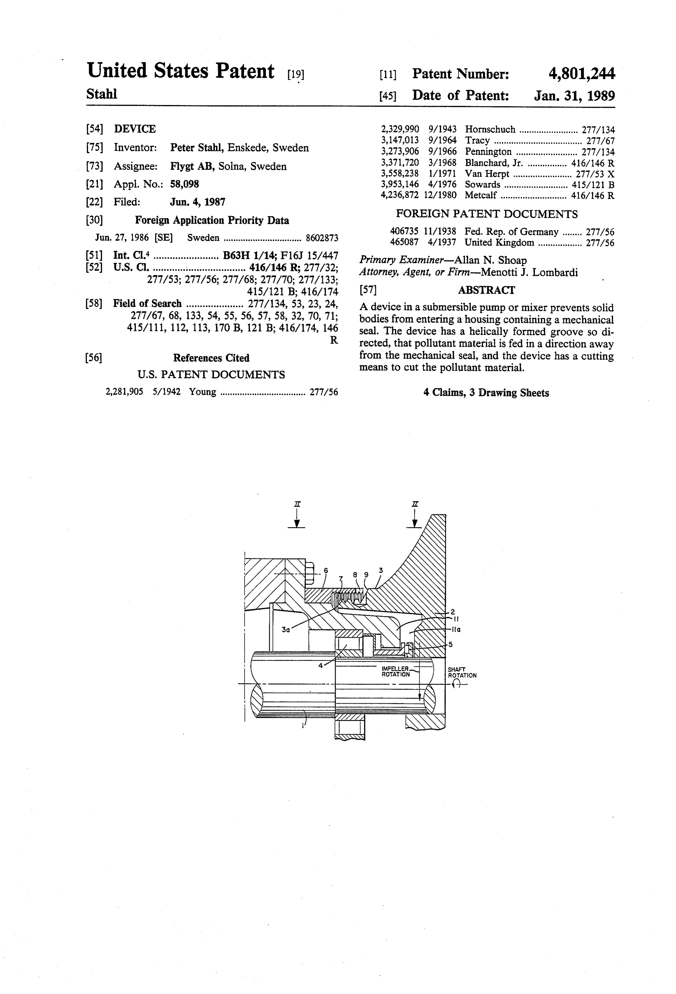
The seal housing is indicated as 11, and the housing area
DEVICE around seal 5 is indicated as 11a.
When the mixer operates vortexes are created under
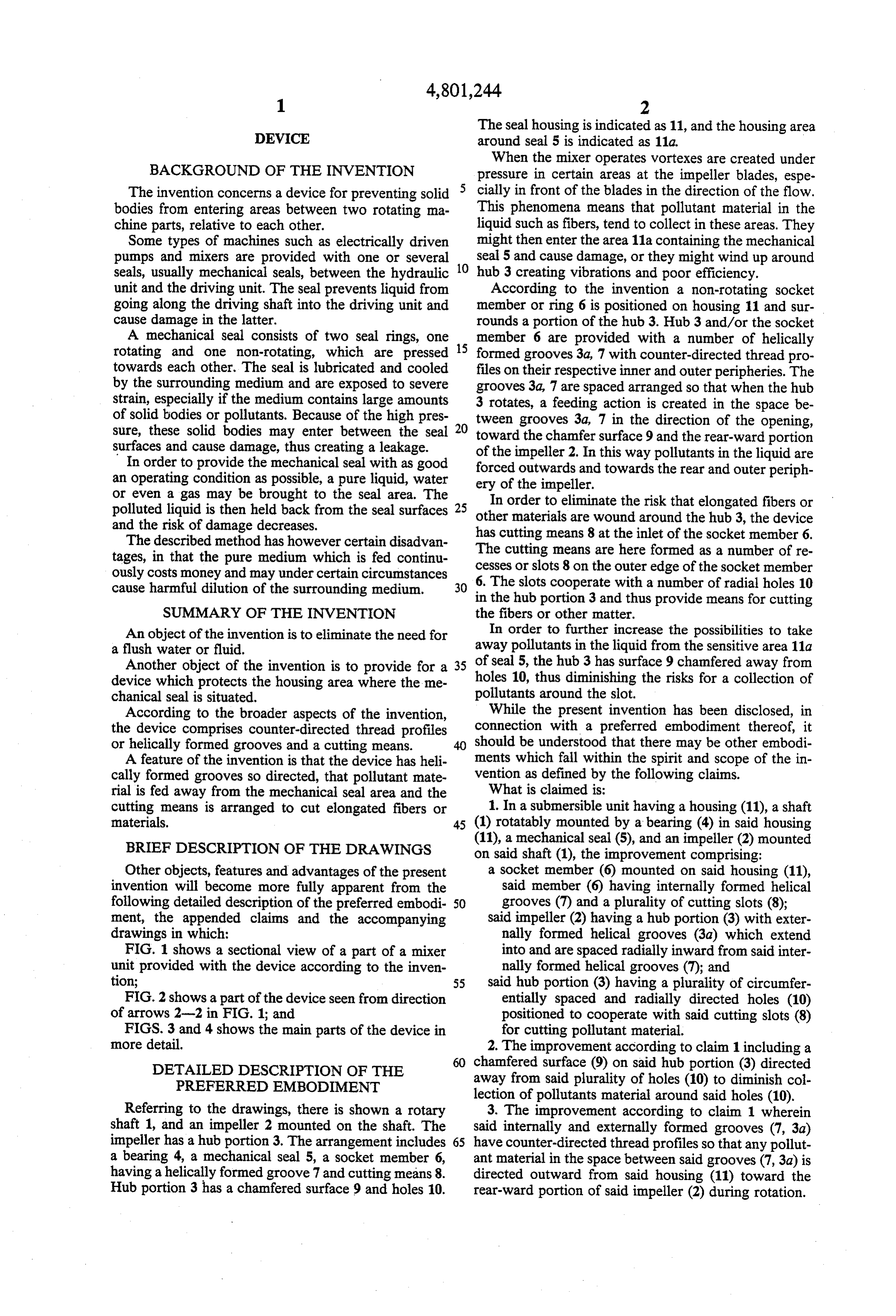
BACKGROUND OF THE INVENTION pressure in certain areas at the impeller blades, espe The invention concerns a device for preventing solid cially in front of the blades in the direction of the flow. bodies from entering areas between two rotating ma This phenomena means that pollutant material in the chine parts, relative to each other. liquid such as fibers, tend to collect in these areas. They Some types of machines such as electrically driven might then enter the area 11a containing the mechanical pumps and mixers are provided with one or several seal 5 and cause damage, or they might wind up around seals, usually mechanical seals, between the hydraulic 10 hub 3 creating vibrations and poor efficiency. unit and the driving unit. The seal prevents liquid from According to the invention a non-rotating socket going along the driving shaft into the driving unit and member or ring 6 is positioned on housing 11 and sur cause damage in the latter. rounds a portion of the hub 3. Hub 3 and/or the socket A mechanical seal consists of two seal rings, one 15 member 6 are provided with a number of helically rotating and one non-rotating, which are pressed formed grooves 3a, 7 with counter-directed thread pro towards each other. The seal is lubricated and cooled files on their respective inner and outer peripheries. The by the surrounding medium and are exposed to severe grooves 3a, 7 are spaced arranged so that when the hub strain, especially if the medium contains large amounts 3 rotates, a feeding action is created in the space be of solid bodies or pollutants. Because of the high pres tween grooves 3a, 7 in the direction of the opening, sure, these solid bodies may enter between the seal 20 toward the chamfer surface 9 and the rear-ward portion surfaces and cause damage, thus creating a leakage. of the impeller 2. In this way pollutants in the liquid are In order to provide the mechanical seal with as good forced outwards and towards the rear and outer periph an operating condition as possible, a pure liquid, water ery of the impeller.
or even a gas may be brought to the seal area. The In order to eliminate the risk that elongated fibers or polluted liquid is then held back from the seal surfaces other materials
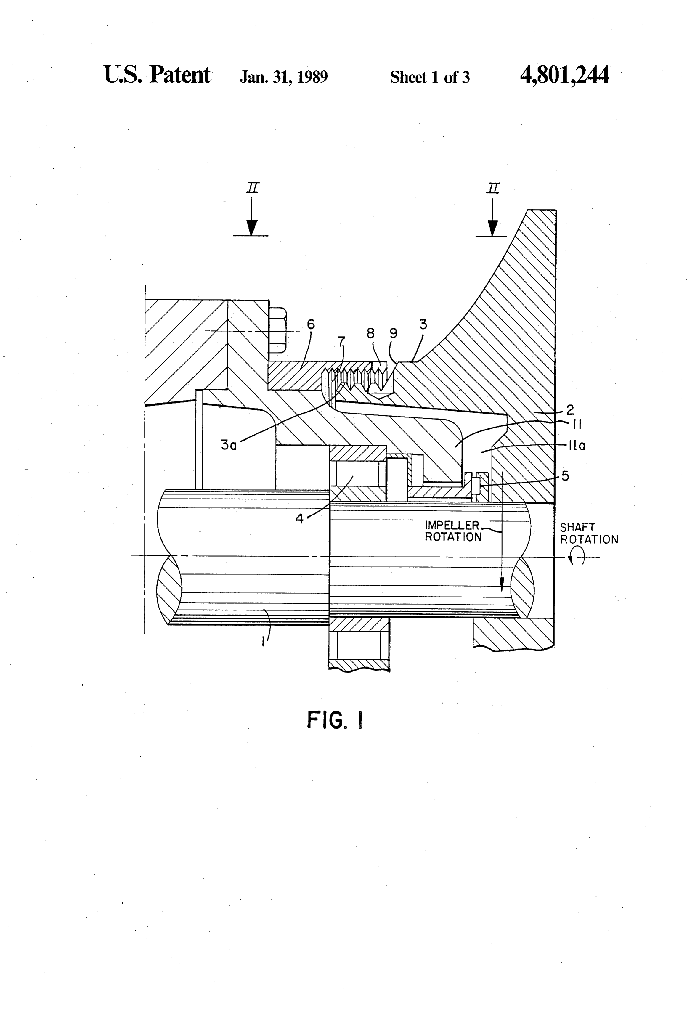
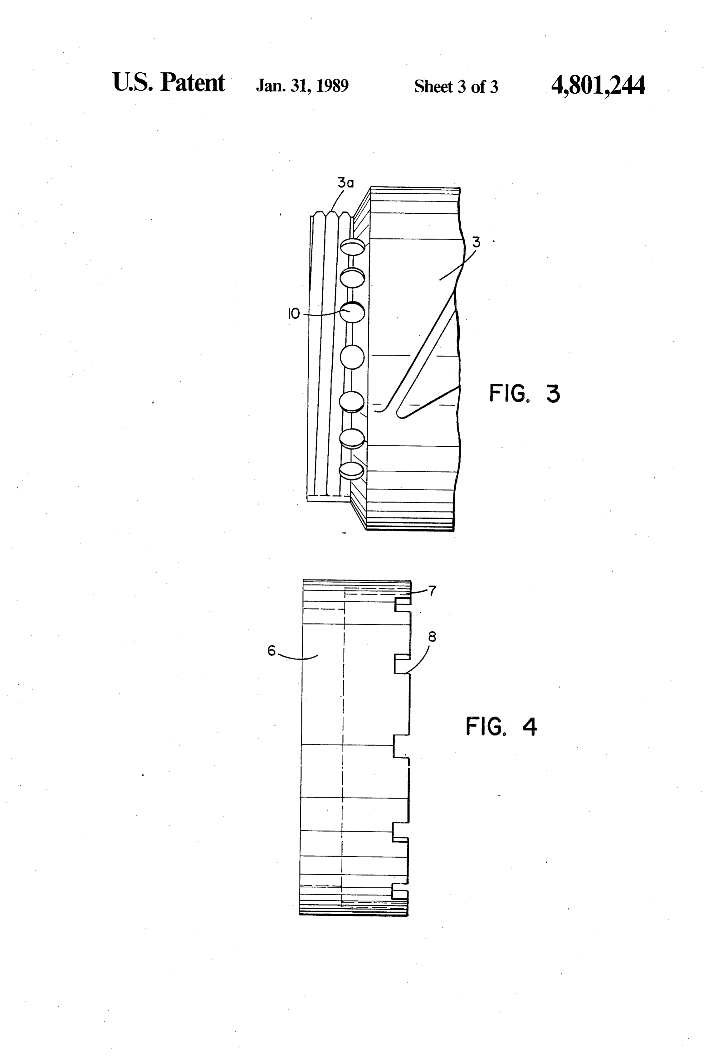
are wound around the hub 3, the device and the risk of damage decreases. has cutting means 8 at the inlet of the socket member 6. The described method has however certain disadvan tages, in that the pure medium which is fed continu The cutting means are here formed as a number of re ously costs money and may under certain circumstances 6. Theor cesses slots 8 on the outer edge of the socket member slots cooperate with a number of radial holes 10 cause harmful dilution of the surrounding medium. 30 in the hub portion 3 and thus provide means for cutting
SUMMARY OF THE INVENTION the fibers or other matter.
An object of the invention is to eliminate the need for In order to further increase the possibilities to take a flush water or fluid. away pollutants in the liquid from the sensitive area 11a Another object of the invention is to provide for a 35 of seal 5, the hub 3 has surface 9 chamfered away from device which protects the housing area where the me holes 10, thus diminishing the risks for a collection of chanical seal is situated. pollutants around the slot.
According to the broader aspects of the invention, While the present invention has been disclosed, in the device comprises counter-directed thread profiles connection with a preferred embodiment thereof, it or helically formed grooves and a cutting means. should be understood that there may be other embodi A feature of the invention is that the device has heli ments which fall within the spirit and scope of the in cally formed grooves so directed, that pollutant mate vention as defined by the following claims. rial is fed away from the mechanical seal area and the What is claimed is:
cutting means is arranged to cut elongated fibers or 1. In a submersible unit having a housing (11), a shaft materials. 45 (1) rotatably mounted by a bearing (4) in said housing
BRIEF DESCRIPTION OF THE DRAWINGS
(11), a mechanical seal (5), and an impeller (2) mounted on said shaft (1), the improvement comprising:
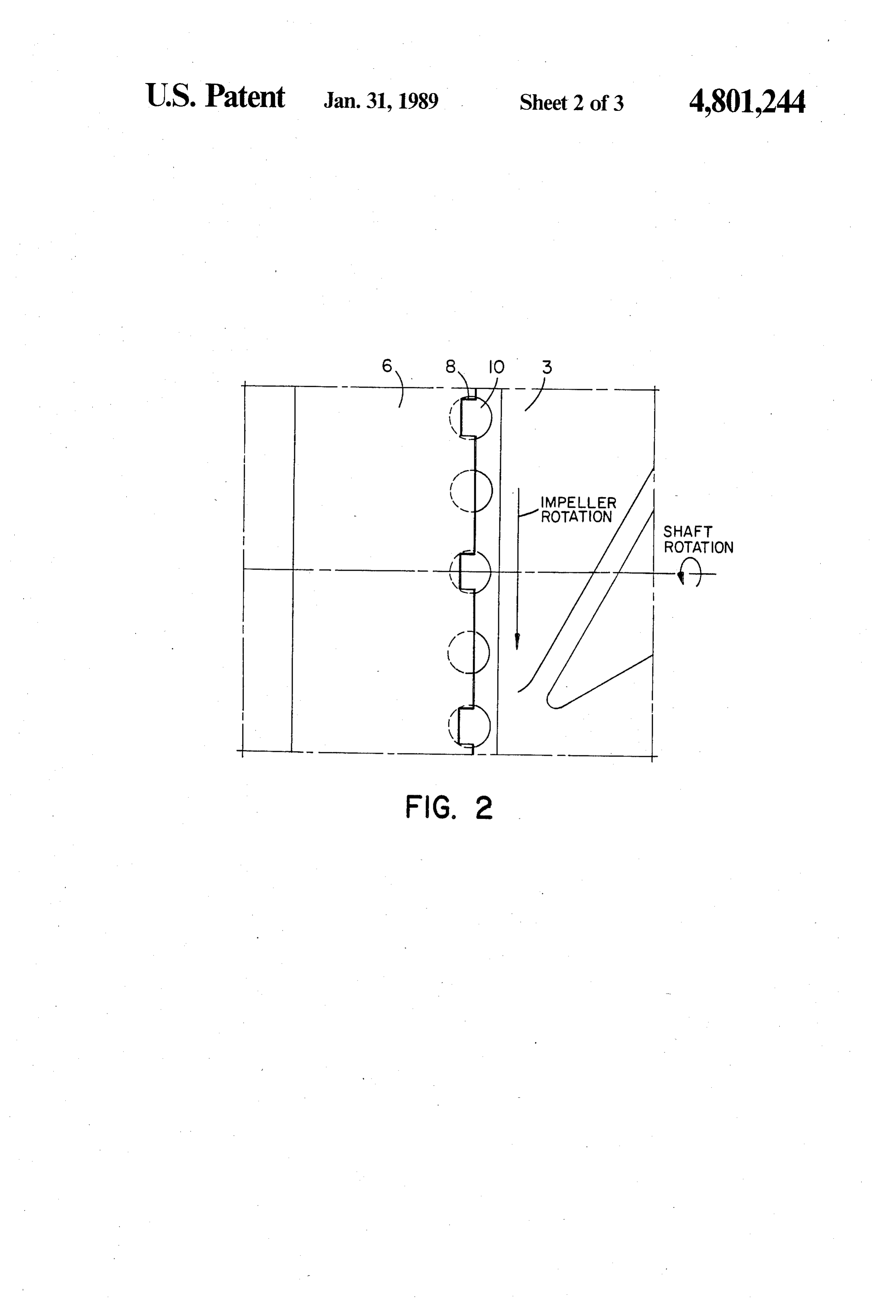
Other objects, features and advantages of the present a socket member (6) mounted on said housing (11), invention will become more fully apparent from the said member (6) having internally formed helical following detailed description of the preferred embodi 50 grooves (7) and a plurality of cutting slots (8); ment, the appended claims and the accompanying said impeller (2) having a hub portion (3) with exter drawings in which: nally formed helical grooves (3.a) which extend FIG. 1 shows a sectional view of a part of a mixer into and are spaced radially inward from said inter unit provided with the device according to the inven nally formed helical grooves (7); and tion; 55 said hub portion (3) having a plurality of circumfer FIG. 2 shows a part of the device seen from direction entially spaced and radially directed holes (10) of arrows 2-2 in FIG. 1; and positioned to cooperate with said cutting slots (8) FIGS. 3 and 4 shows the main parts of the device in for cutting pollutant material. more detail. 2. The improvement according to claim 1 including a DETALED DESCRIPTION OF THE chamfered surface (9) on said hub portion (3) directed PREFERRED EMBODIMENT away from said plurality of holes (10) to diminish col lection of pollutants material around said holes (10).
Referring to the drawings, there is shown a rotary 3. The improvement according to claim 1 wherein shaft 1, and an impeller 2 mounted on the shaft. The said internally and externally formed grooves (7, 3a) impeller has a hub portion 3. The arrangement includes 65 have counter-directed thread profiles so that any pollut a bearing 4, a mechanical seal 5, a socket member 6, ant material in the space between said grooves (7,3a) is having a helically formed groove 7 and cutting means 8. directed outward from said housing (11) toward the Hub portion 3 has a chamfered surface 9 and holes 10. rear-ward portion of said impeller (2) during rotation.
Page 6
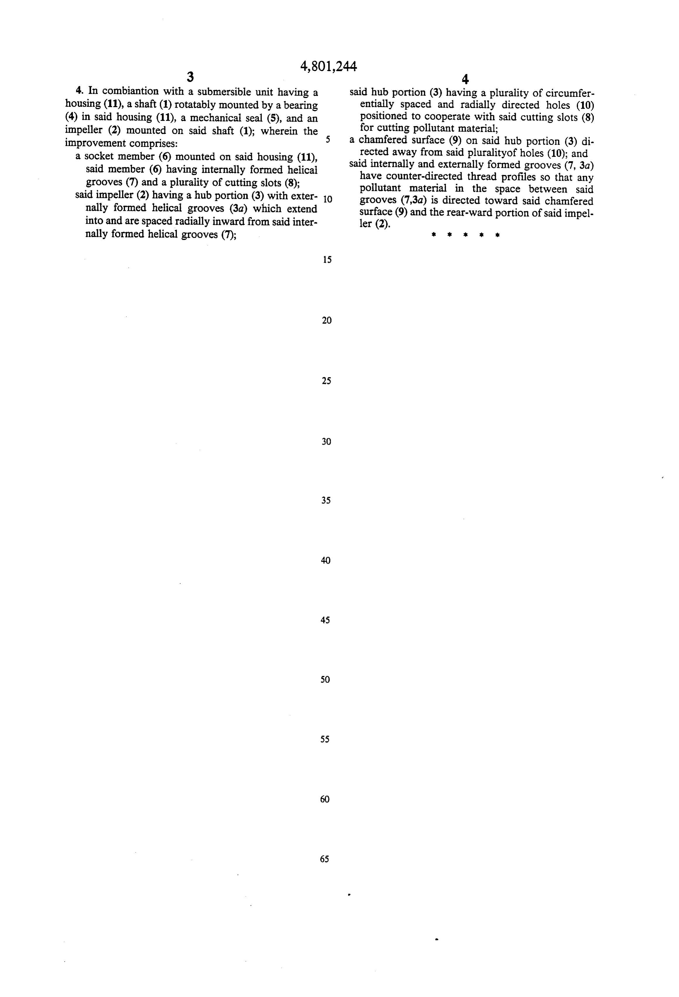
4. In combiantion with a submersible unit having a said hub portion (3) having a plurality of circumfer housing (11), a shaft (1) rotatably mounted by a bearing entially spaced and radially directed holes (10) (4) in said housing (11), a mechanical seal (5), and an positioned to cooperate with said cutting slots (8) impeller (2) mounted on said shaft (1); wherein the for cutting pollutant material; improvement comprises: a chamfered surface (9) on said hub portion (3) di a socket member (6) mounted on said housing (11), rected away from said pluralityof holes (10); and said member (6) having internally formed helical said internally and externally formed grooves (7, 3a) grooves (7) and a plurality of cutting slots (8); have counter-directed thread profiles so that any said impeller (2) having a hub portion (3) with exter 10 pollutant material in the space between said nally formed helical grooves (3.a) which extend grooves (7,3a) is directed toward said chamfered surface (9) and the rear-ward portion of said impel into and are spaced radially inward from said inter ler (2).
nally formed helical grooves (7);
Provenance
- Collection
- Cited prior art
- Original PDF
- patentimages.storage.googleapis.com →
- Filed
- 1987-06-04
- Pages
- 6
- Method
- pdftotext (the PDF's own text layer) + pdftoppm 300dpi page scans
- Source
- Google Patents bibliographic record
- Granted
- 1989-01-31
- Inventors
- Peter Stahl; Flygt AB
- Transcribed from
- patentimages.storage.googleapis.com →