patent · US3957031
Light collectors in cylindrical geometry
18 May 1976
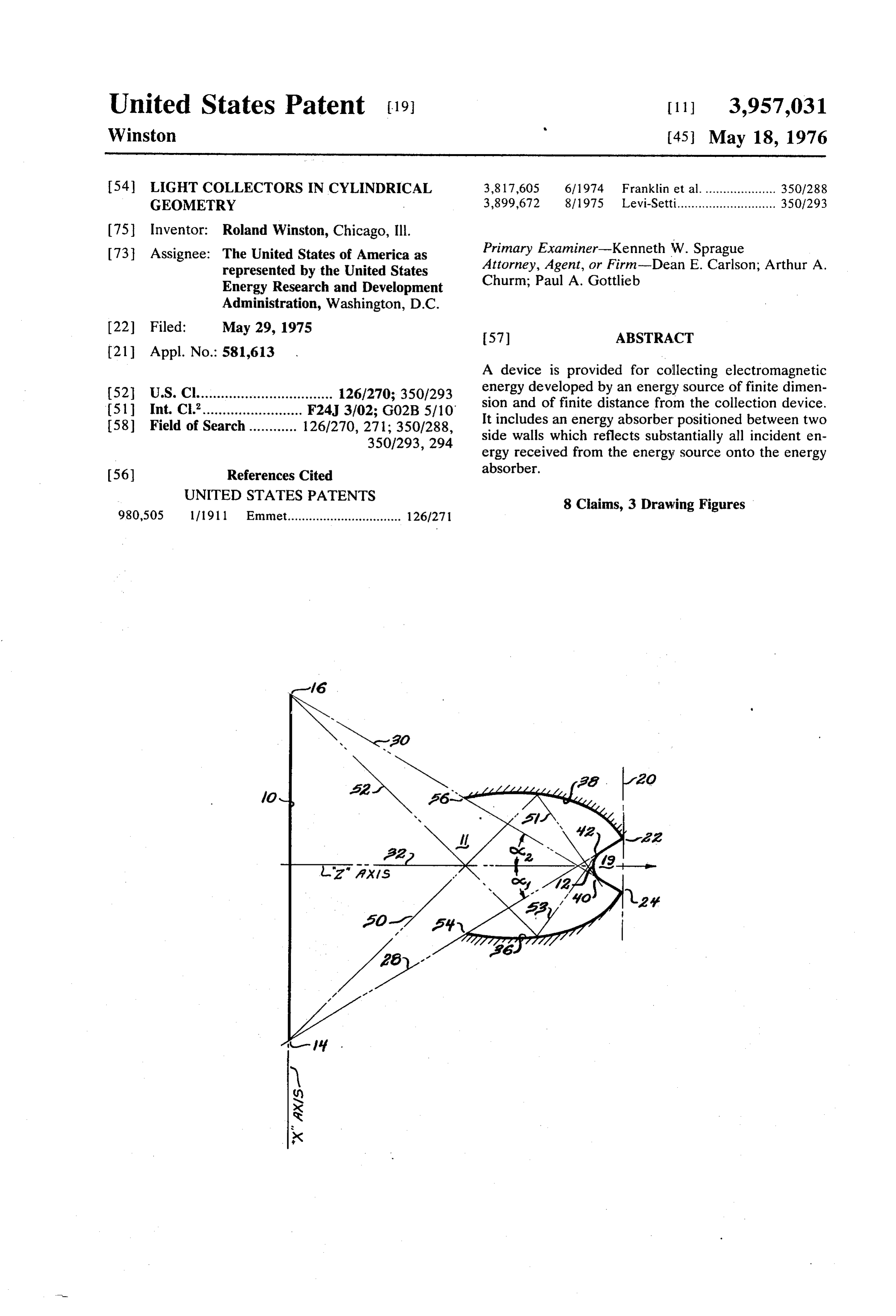
Page 1 — bibliographic record
United States Patent (19) 11 3,957,031 Winston (45) May 18, 1976 54) LIGHT COLLECTORS IN CYLINDRICAL 3,817,605 6/1974 Franklin et al..................... 350/288 GEOMETRY 3,899,672 8/1975 Levi-Setti............................ 350,1293 (75) Inventor: Roland Winston, Chicago, Ill.
73 Assignee: The United States of America as Primary Examiner-Kenneth W. Sprague represented by the United States Attorney, Agent, or Firm-Dean E. Carlson; Arthur A. Energy Research and Development Churm; Paul A. Gottlieb
Administration, Washington, D.C.
22) Filed: May 29, 1975 57) ABSTRACT
A device is provided for collecting electromagnetic 52 U.S. Cl.................................. 126/270; 350/293 energy developed by an energy source of finite dimen 51 Int. C.’......................... F24J 3/02; G02B 5/10 sion and of finite distance from the collection device. 58) Field of Search ............ 126/270, 271; 350/288, It includes an energy absorber positioned between two 350/293,294 side walls which reflects substantially all incident en ergy received from the energy source onto the energy 56) References Cited absorber.
UNITED STATES PATENTS
8 Claims, 3 Drawing Figures 980,505 1/1911 Emmet................................ 1261271
Page 2
Drawing sheet — no readable text.
Page 3
Drawing sheet — no readable text.
Page 4
i shaped that all energy directed from the conjugate edge
LIGHT COLLECTORS IN CYLINEDRICAL of the energy source intersecting the axis of the ab GEOMETRY sorber at any angle, and striking any point on the wall, is directed along a line tangent to the energy receiver.
CONTRACTUAL ORIGIN OF THE INVENTION 5 Each wall extends no more than to a line from the
The invention described herein was made in the second edge of the energy source, conjugate to the course of, or under, a contract with the UNITED other side wall, to a point of tangency with the energy STATES ENERGY RESEARCH AND DEVELOP absorber along the first axis.
MENT ADMINISTRATION.
10 BRIEF DESCRIPTION OF THE DRAWINGS
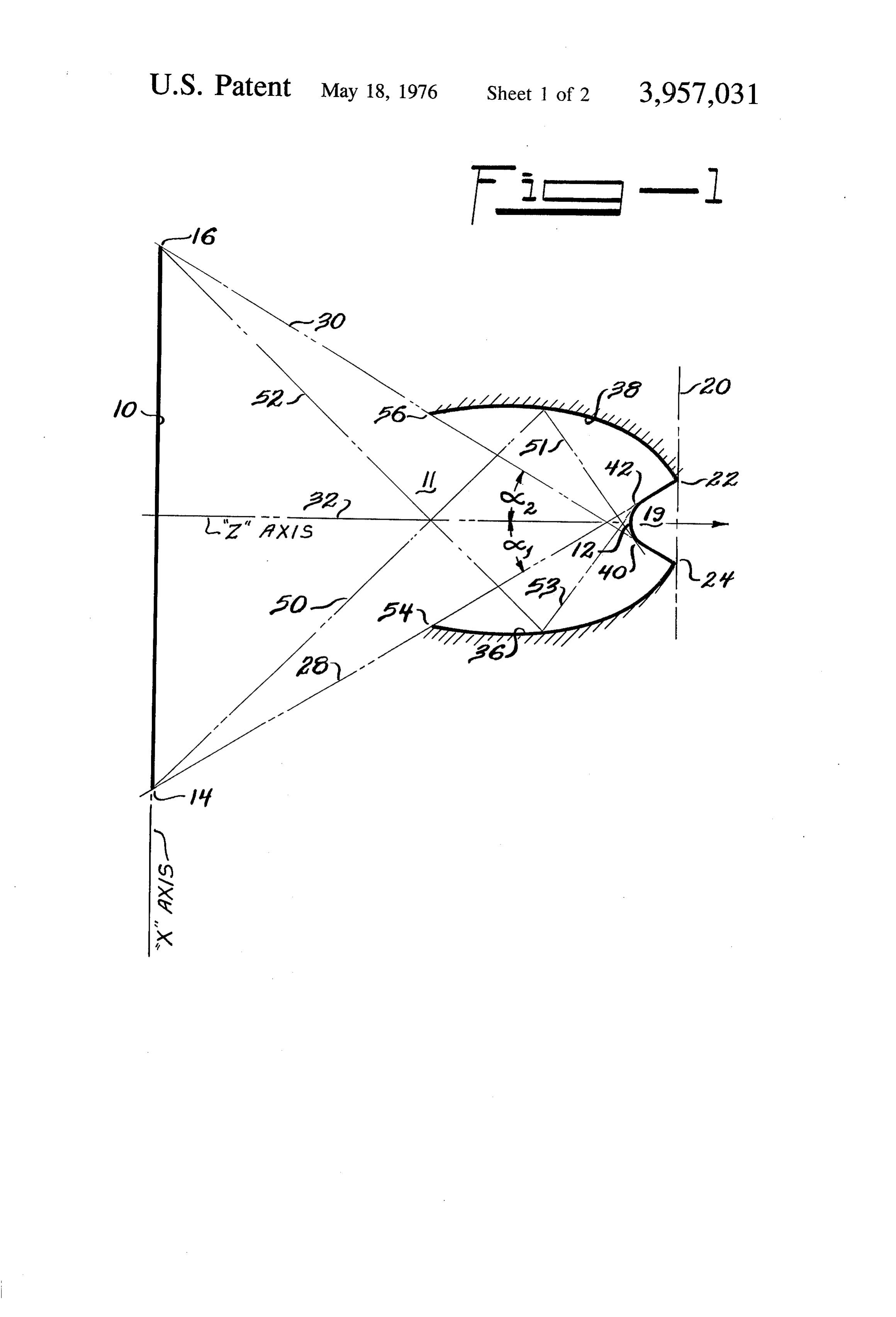
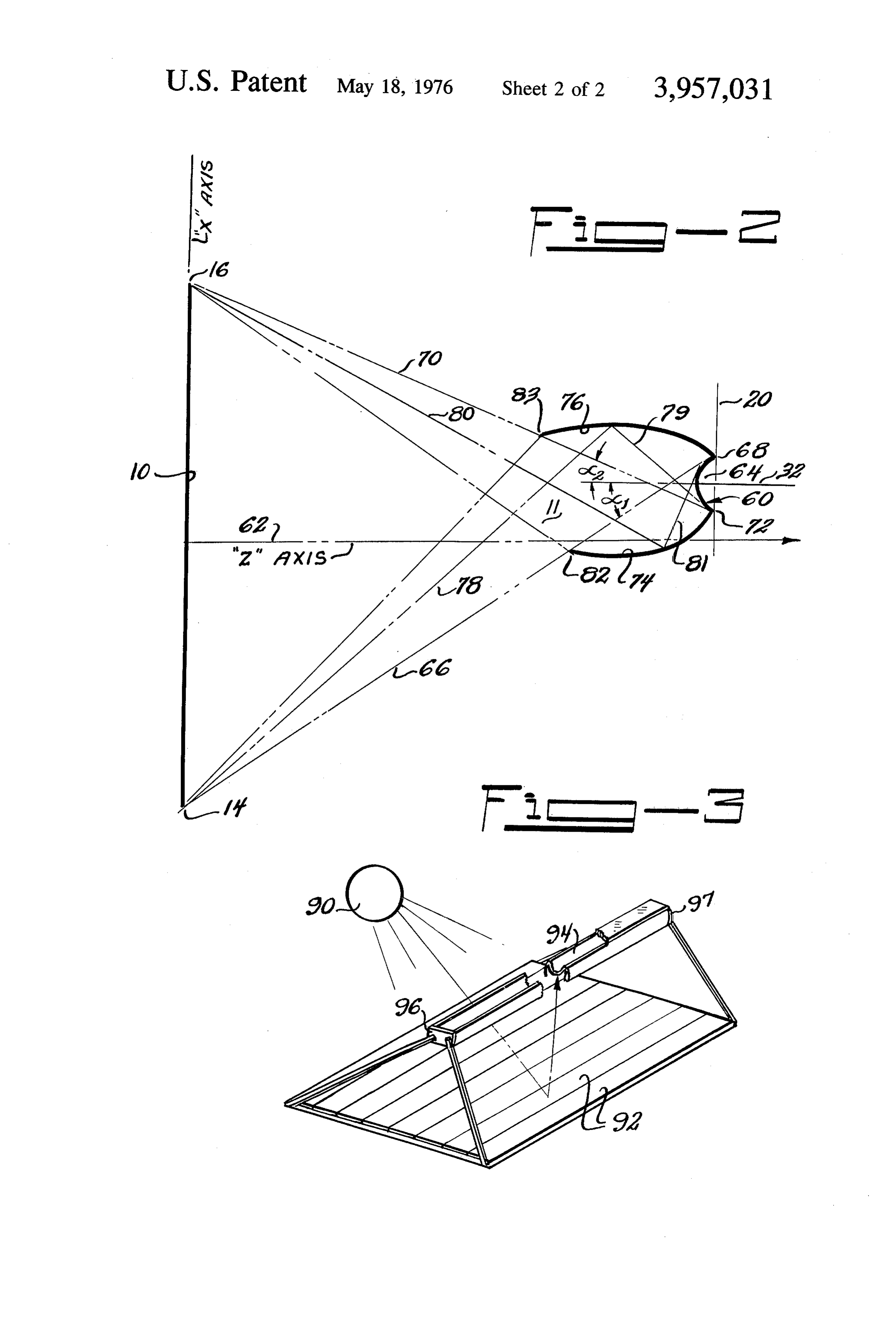
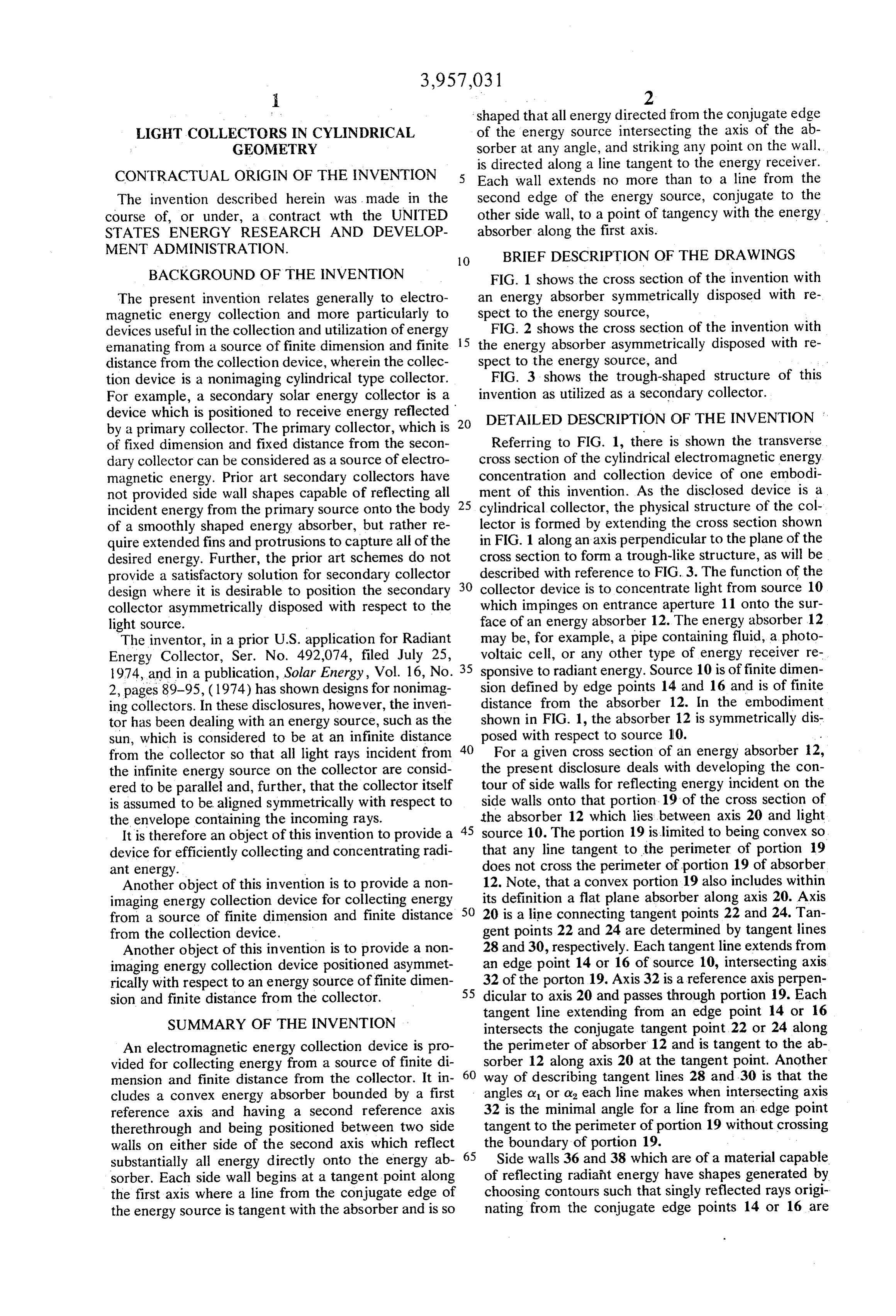
BACKGROUND OF THE INVENTION FIG. 1 shows the cross section of the invention with The present invention relates generally to electro an energy absorber symmetrically disposed with re magnetic energy collection and more particularly to spect to the energy source, devices useful in the collection and utilization of energy FIG. 2 shows the cross section of the invention with emanating from a source of finite dimension and finite 5 the energy absorber asymmetrically disposed with re distance from the collection device, wherein the collec spect to the energy source, and tion device is a nonimaging cylindrical type collector. FIG. 3 shows the trough-shaped structure of this For example, a secondary solar energy collector is a invention as utilized as a secondary collector. device which is positioned to receive energy reflected 20 DETAILED DESCRIPTION OF THE INVENTION by a primary collector. The primary collector, which is of fixed dimension and fixed distance from the secon Referring to FIG. 1, there is shown the transverse dary collector can be considered as a source of electro cross section of the cylindrical electromagnetic energy magnetic energy. Prior art secondary collectors have concentration and collection device of one embodi not provided side wall shapes capable of reflecting all ment of this invention. As the disclosed device is a incident energy from the primary source onto the body 25 cylindrical collector, the physical structure of the col of a smoothly shaped energy absorber, but rather re lector is formed by extending the cross section shown quire extended fins and protrusions to capture all of the in FIG. 1 along an axis perpendicular to the plane of the desired energy. Further, the prior art schemes do not cross section to form a trough-like structure, as will be provide a satisfactory solution for secondary collector 30 described with reference to FIG.3. The function of the design where it is desirable to position the secondary collector device is to concentrate light from source 10 collector asymmetrically disposed with respect to the which impinges on entrance aperture 11 onto the sur light source. face of an energy absorber 12. The energy absorber 12 The inventor, in a prior U.S. application for Radiant voltaicmay be, for example, a pipe containing fluid, a photo Energy Collector, Ser. No. 492,074, filed July 25, 35 cell, or any other type of energy receiver re 1974, and in a publication, Solar Energy, Vol. 16, No. sponsive to radiant energy. Source 10 is of finite dimen 2, pages 89-95, (1974) has shown designs for nonimag sion defined by edge points 14 and 16 and is of finite ing collectors. In these disclosures, however, the inven distance from the absorber 12. In the embodiment tor has been dealing with an energy source, such as the shown in FIG. 1, the absorber 12 is symmetrically dis sun, which is considered to be at an infinite distance 40 posed with respect to source 10. from the collector so that all light rays incident from For a given cross section of an energy absorber 12, the infinite energy source on the collector are consid the present disclosure deals with developing the con ered to be parallel and, further, that the collector itself tour of side walls for reflecting energy incident on the is assumed to be aligned symmetrically with respect to side walls onto that portion. 19 of the cross section of the envelope containing the incoming rays. the absorber 12 which lies between axis 20 and light It is therefore an object of this invention to provide a 45 source 10. The portion 19 is limited to being convex so device for efficiently collecting and concentrating radi that any line tangent to the perimeter of portion 19 ant energy. does not cross the perimeter of portion 19 of absorber Another object of this invention is to provide a non 12. Note, that a convex portion 19 also includes within imaging energy collection device for collecting energy its definition a flat plane absorber along axis 20. Axis from a source of finite dimension and finite distance 50 20 is a line connecting tangent points 22 and 24. Tan from the collection device. gent points 22 and 24 are determined by tangent lines Another object of this invention is to provide a non 28 and 30, respectively. Each tangent line extends from imaging energy collection device positioned asymmet an edge point 14 or 16 of source 10, intersecting axis rically with respect to an energy source of finite dimen 55 32 of the porton 19. Axis 32 is a reference axis perpen sion and finite distance from the collector. dicular to axis 20 and passes through portion 19. Each tangent line extending from an edge point 14 or 16
SUMMARY OF THE INVENTION intersects the conjugate tangent point 22 or 24 along An electromagnetic energy collection device is pro the perimeter of absorber 12 and is tangent to the ab vided for collecting energy from a source of finite di sorber 12 along axis 20 at the tangent point. Another mension and finite distance from the collector. It in 60 way of describing tangent lines 28 and 30 is that the cludes a convex energy absorber bounded by a first angles or or o, each line makes when intersecting axis reference axis and having a second reference axis 32 is the minimal angle for a line from an edge point therethrough and being positioned between two side tangent to the perimeter of portion 19 without crossing walls on either side of the second axis which reflect the boundary of portion 19. substantially all energy directly onto the energy ab 65 Side walls 36 and 38 which are of a material capable sorber. Each side wall begins at a tangent point along of reflecting radiaht energy have shapes generated by the first axis where a line from the conjugate edge of choosing contours such that singly reflected rays origi the energy source is tangent with the absorber and is so nating from the conjugate edge points 14 or 16 are
Page 5
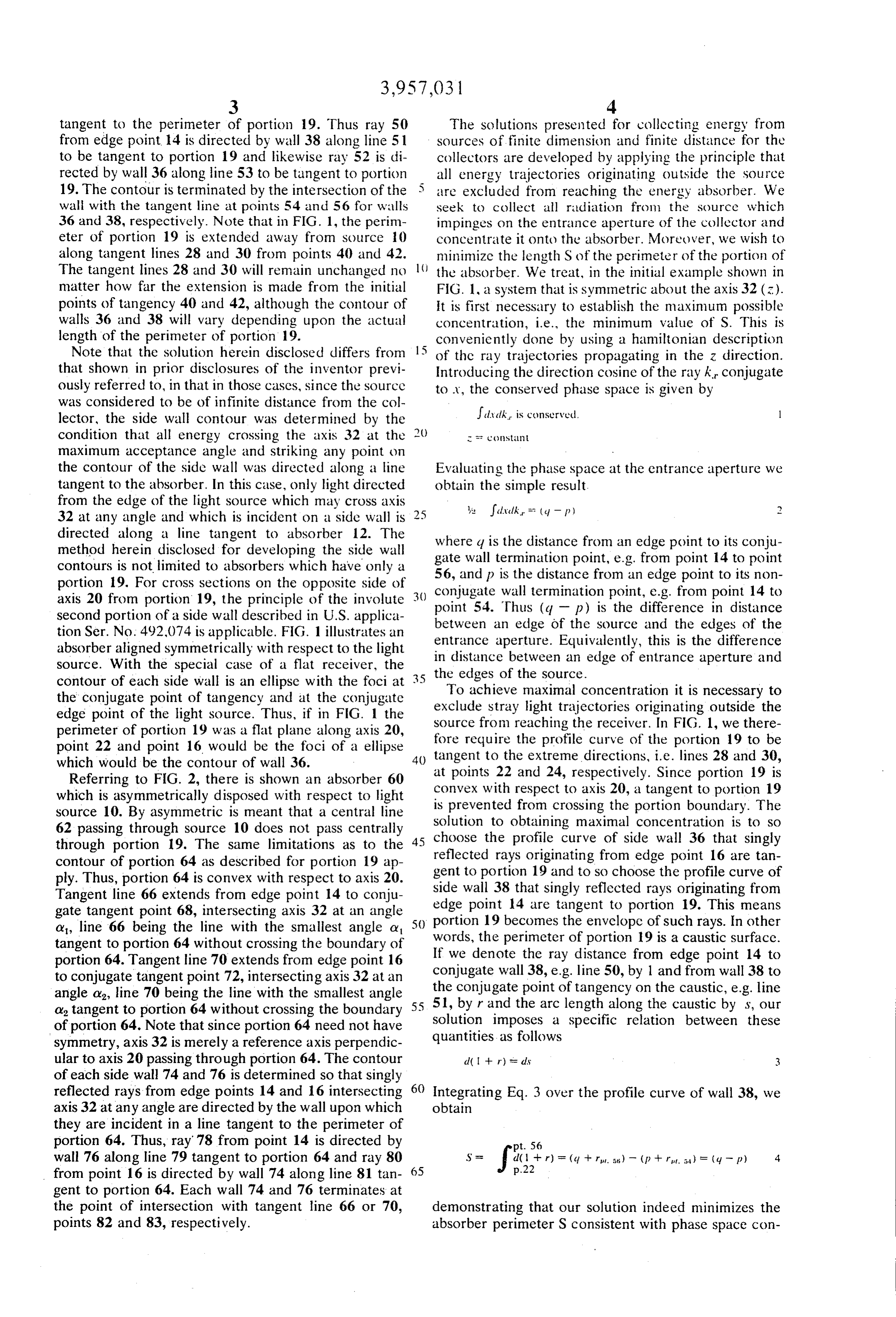
tangent to the perimeter of portion 19. Thus ray 50 The solutions presented for collecting energy from from edge point 14 is directed by wall 38 along line 51 sources of finite dimension and finite distance for the to be tangent to portion 19 and likewise ray 52 is di collectors are developed by applying the principle that rected by wall 36 along line 53 to be tangent to portion 5 all energy trajectories originating Outside the Source 19. The contour is terminated by the intersection of the are excluded from reaching the energy absorber. We wall with the tangent line at points 54 and 56 for walls seek to collect all radiation from the source which 36 and 38, respectively. Note that in FIG. 1, the perim impinges on the entrance aperture of the collector and eter of portion 19 is extended away from source 10 concentrate it onto the absorber. Moreover, we wish to along tangent lines 28 and 30 from points 40 and 42. minimize the length S of the perimeter of the portion of The tangent lines 28 and 30 will remain unchanged no () the absorber. We treat, in the initial example shown in matter how far the extension is made from the initial FIG. 1, a system that is symmetric about the axis 32 (3). points of tangency 40 and 42, although the contour of It is first necessary to establish the maximum possible walls 36 and 38 will vary depending upon the actual concentration, i.e., the minimum value of S. This is length of the perimeter of portion. 19. conveniently done by using a hamiltonian description Note that the solution herein disclosed differs from 15 of the ray trajectories propagating in the z direction. that shown in prior disclosures of the inventor previ introducing the direction cosine of the ray k, conjugate ously referred to, in that in those cases, since the source to A, the conserved phase space is given by was considered to be of infinite distance from the col lector, the side wall contour was determined by the Jal dk is conserved. l condition that all energy crossing the axis 32 at the () r st:
maximum acceptance angle and striking any point on the contour of the side wall was directed along a line Evaluating the phase space at the entrance aperture we tangent to the absorber. In this case, only light directed obtain the simple result.
from the edge of the light source which may cross axis ye ?alvalk. - (4 - p) 32 at any angle and which is incident on a side wall is directed along a line tangent to absorber 12. The where q is the distance from an edge point to its conju method herein disclosed for developing the side wall gate wall termination point, e.g. from point 14 to point contours is not limited to absorbers which have only a 56, and p is the distance from an edge point to its non portion 19. For cross sections on the opposite side of conjugate wall termination point, e.g. from point 14 to axis 20 from portion 19, the principle of the involute point 54. Thus (q - p) is the difference in distance second portion of a side wall described in U.S. applica between an edge of the source and the edges of the tion Ser. No. 492,074 is applicable. FIG. 1 illustrates an entrance aperture. Equivalently, this is the difference absorber aligned symmetrically with respect to the light in distance between an edge of entrance aperture and source. With the special case of a flat receiver, the the edges of the source.
contour of each side wall is an ellipse with the foci at To achieve maximal concentration it is necessary to the conjugate point of tangency and at the conjugate exclude Stray light trajectories originating outside the edge point of the light source. Thus, if in FIG. 1 the source from reaching the receiver. In FIG. 1, we there perimeter of portion 19 was a flat plane along axis 20, fore require the profile curve of the portion 19 to be point 22 and point 16 would be the foci of a ellipse which would be the contour of wall 36. 40 tangent to the extreme directions, i.e. lines 28 and 30, Referring to FIG. 2, there is shown an absorber 60 at points 22 and 24, respectively. Since portion 19 is convex with respect to axis 20, a tangent to portion 19 which is asymmetrically disposed with respect to light is prevented from crossing the portion boundary. The source 10. By asymmetric is meant that a central line Solution to obtaining maximal concentration is to so 62 passing through source 10 does not pass centrally choose the profile curve through portion 19. The same limitations as to the reflected rays originating from of side wall 36 that singly contour of portion 64 as described for portion 19 ap gent to portion 19 and to so choose edge point 16 are tan ply. Thus, portion 64 is convex with respect to axis 20. the profile curve of Tangent line 66 extends from edge point 14 to conju side wall 38 that singly reflected rays originating from gate tangent point 68, intersecting axis 32 at an angle edge point 14 are tangent to portion 19. This means o, line 66 being the line with the smallest angle a 50 portion 19 becomes the envelope of such rays. In other tangent to portion 64 without crossing the boundary of words, the perimeter of portion 19 is a caustic surface. portion 64. Tangent line 70 extends from edge point 16 If we denote the ray distance from edge point 14 to to conjugate tangent point 72, intersecting axis 32 at an conjugate wall 38, e.g. line 50, by 1 and from wall 38 to angle a line 70 being the line with the smallest angle the conjugate point of tangency on the caustic, e.g. line a tangent to portion 64 without crossing the boundary 55 51, by r and the arc length along the caustic by s, our Solution imposes a specific relation between these of portion 64. Note that since portion 64 need not have quantities symmetry, axis 32 is merely a reference axis perpendic as follows ular to axis 20 passing through portion 64. The contour d( -- r) se dis 3 of each side wall 74 and 76 is determined so that singly reflected rays from edge points 14 and 16 intersecting 60 Integrating Eq. 3 over the profile curve of wall 38, we axis 32 at any angle are directed by the wall upon which obtain they are incident in a line tangent to the perimeter of portion 64. Thus, ray 78 from point 14 is directed by pt. 56 wall 76 along line 79 tangent to portion 64 and ray 80 from point 16 is directed by wall 74 along line 81 tan 65
gent to portion 64. Each wall 74 and 76 terminates at the point of intersection with tangent line 66 or 70, demonstrating that our solution indeed minimizes the points 82 and 83, respectively. absorber perimeter S consistent with phase space con
Page 6
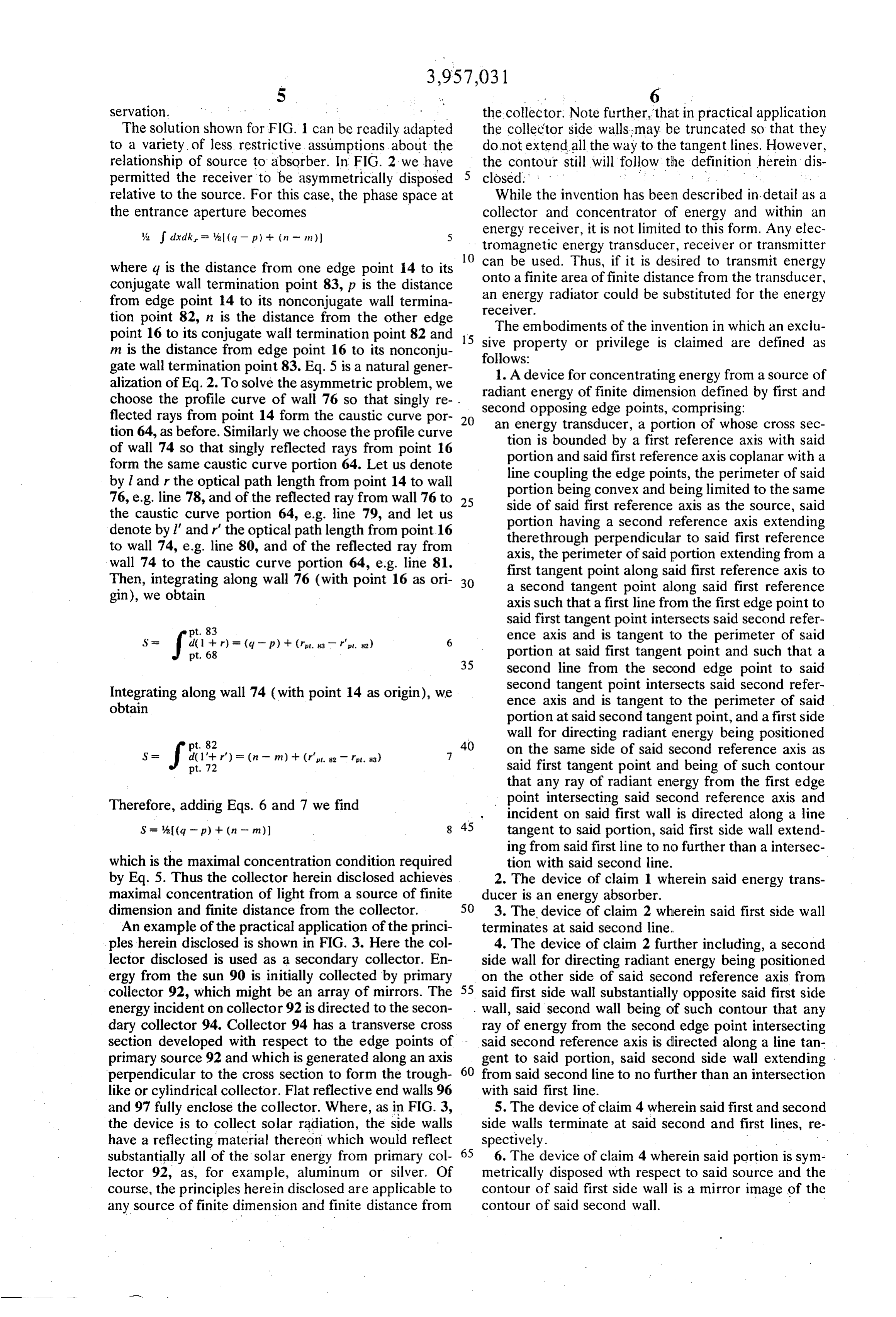
Servation. the collector. Note further, that in practical application The solution shown for FIG. 1 can be readily adapted the collector side walls may be truncated so that they to a variety of less, restrictive assumptions about the do not extend all the way to the tangent lines. However, relationship of source to absorber. In FIG. 2 we have the contour still will follow the definition herein dis permitted the receiver to be asymmetrically disposed closed. : . . . . . relative to the source. For this case, the phase space at While the invention has been described in detail as a the entrance aperture becomes collector and concentrator of energy and within an A. dx.dk = a(q - p) + (n - m) 5 energy receiver, it is not limited to this form. Any elec tromagnetic energy transducer, receiver or transmitter
can be used. Thus, if it is desired to transmit energy where q is the distance from one edge point 14 to its onto a finite area of finite distance from the transducer, conjugate wall termination point 83, p is the distance from edge point 14 to its nonconjugate wall termina an energy radiator could be substituted for the energy tion point 82, n is the distance from the other edge receiver.
point 16 to its conjugate wall termination point 82 and 15 siveTheproperty embodiments of the invention in which an exclu or privilege is claimed are defined as m is the distance from edge point 16 to its nonconju follows:
gate wall termination point 83. Eq. 5 is a natural gener 1. A device for concentrating energy from a source of alization of Eq. 2. To solve the asymmetric problem, we radiant energy of finite dimension defined by first and choose the profile curve of wall 76 so that singly re flected rays from point 14 form the caustic curve por 20 second opposing edge points, comprising: an energy transducer, a portion of whose cross sec tion 64, as before. Similarly we choose the profile curve tion is bounded by a first reference axis with said of wall 74 so that singly reflected rays from point 16 portion and said first reference axis coplanar with a form the same caustic curve portion 64. Let us denote line coupling the edge points, the perimeter of said by land r the optical path length from point 14 to wall portion being convex and being limited to the same 76, e.g. line 78, and of the reflected ray from wall 76 to 25 side of said first reference axis as the source, said the caustic curve portion 64, e.g. line 79, and let us portion having a second reference axis extending denote by l' and r' the optical path length from point 16 therethrough perpendicular to said first reference to wall 74, e.g. line 80, and of the reflected ray from axis, the perimeter of said portion extending from a wall 74 to the caustic curve portion 64, e.g. line 81. first tangent point along said first reference axis to Then, integrating along wall 76 (with point 16 as ori 30 a second tangent point along said first reference gin), we obtain axis such that a first line from the first edge point to
said first tangent point intersects said second refer ence axis and is tangent to the perimeter of said
pt. 68 (-p) + (re-r'. 6 35 portion at said first tangent point and such that a second line from the second edge point to said
Integrating along wall 74 (with point 14 as origin), we second tangent point intersects said second refer obtain ence axis and is tangent to the perimeter of said portion at said second tangent point, and a first side
wall for directing radiant energy being positioned 40 on the same side of said second reference axis as
S = Jarir) pt. 72 - (n-m) + (r. 82 pt. 83) 7 said first tangent point and being of such contour that any ray of radiant energy from the first edge
Therefore, adding Eqs. 6 and 7 we find point intersecting said second reference axis and incident on said first wall is directed along a line
S = %(q - p) + (n - m) 8 45 tangent to said portion, said first side wall extend ing from said first line to no further thana intersec which is the maximal concentration condition required tion with said second line.
by Eq. 5. Thus the collector herein disclosed achieves 2. The device of claim 1 wherein said energy trans maximal concentration of light from a source of finite ducer is an energy absorber.
dimension and finite distance from the collector. 50 3. The device of claim 2 wherein said first side wall An example of the practical application of the princi terminates at said second line.
ples herein disclosed is shown in FIG. 3. Here the col 4. The device of claim 2 further including, a second lector disclosed is used as a secondary collector. En side wall for directing radiant energy being positioned ergy from the sun 90 is initially collected by primary on the other side of said second reference axis from collector 92, which might be an array of mirrors. The 55 said first side wall substantially opposite said first side energy incident on collector 92 is directed to the secon wall, said second wall being of such contour that any dary collector 94. Collector 94 has a transverse cross ray of energy from the second edge point intersecting section developed with respect to the edge points of said second reference axis is directed along a line tan primary source 92 and which is generated along an axis gent to said portion, said second side wall extending perpendicular to the cross section to form the trough 60 from said second line to no further than an intersection like or cylindrical collector. Flat reflective end walls 96 with said first line.
and 97 fully enclose the collector. Where, as in FIG. 3, 5. The device of claim 4 wherein said first and second the device is to collect solar radiation, the side walls side walls terminate at said second and first lines, re have a reflecting material thereon which would reflect spectively.
substantially all of the solar energy from primary col 65 6. The device of claim 4 wherein said portion is sym lector 92, as, for example, aluminum or silver. Of metrically disposed with respect to said source and the course, the principles herein disclosed are applicable to contour of said first side wall is a mirror image of the any source of finite dimension and finite distance from contour of said second wall.
Page 7
7. The device of claim 4 wherein said energy ab- 8. The device of claim 7 wherein said source is a sorber extends - along a third reference axis perpendicu - rimary solar energy collector and said device is posi lar to said first and second reference axes, said first and - E. ned y • Y E. ! collector to concentrate e. second side walls also extending in the direction of said Ioned as a secondary co gy third axis and being parallel thereto to form a trough- 5 directed thereto by cksaidski primary like structure.
collector.
Provenance
- Collection
- Cited prior art
- Original PDF
- patentimages.storage.googleapis.com →
- Filed
- 1975-05-29
- Pages
- 7
- Method
- pdftotext (the PDF's own text layer) + pdftoppm 300dpi page scans
- Source
- Google Patents bibliographic record
- Granted
- 1976-05-18
- Inventors
- Roland Winston; Energy Research and Development Administration ERDA
- Transcribed from
- patentimages.storage.googleapis.com →