patent · US4723826
Lens type solar collector requiring no orientation system
9 February 1988
Page 1 — bibliographic record
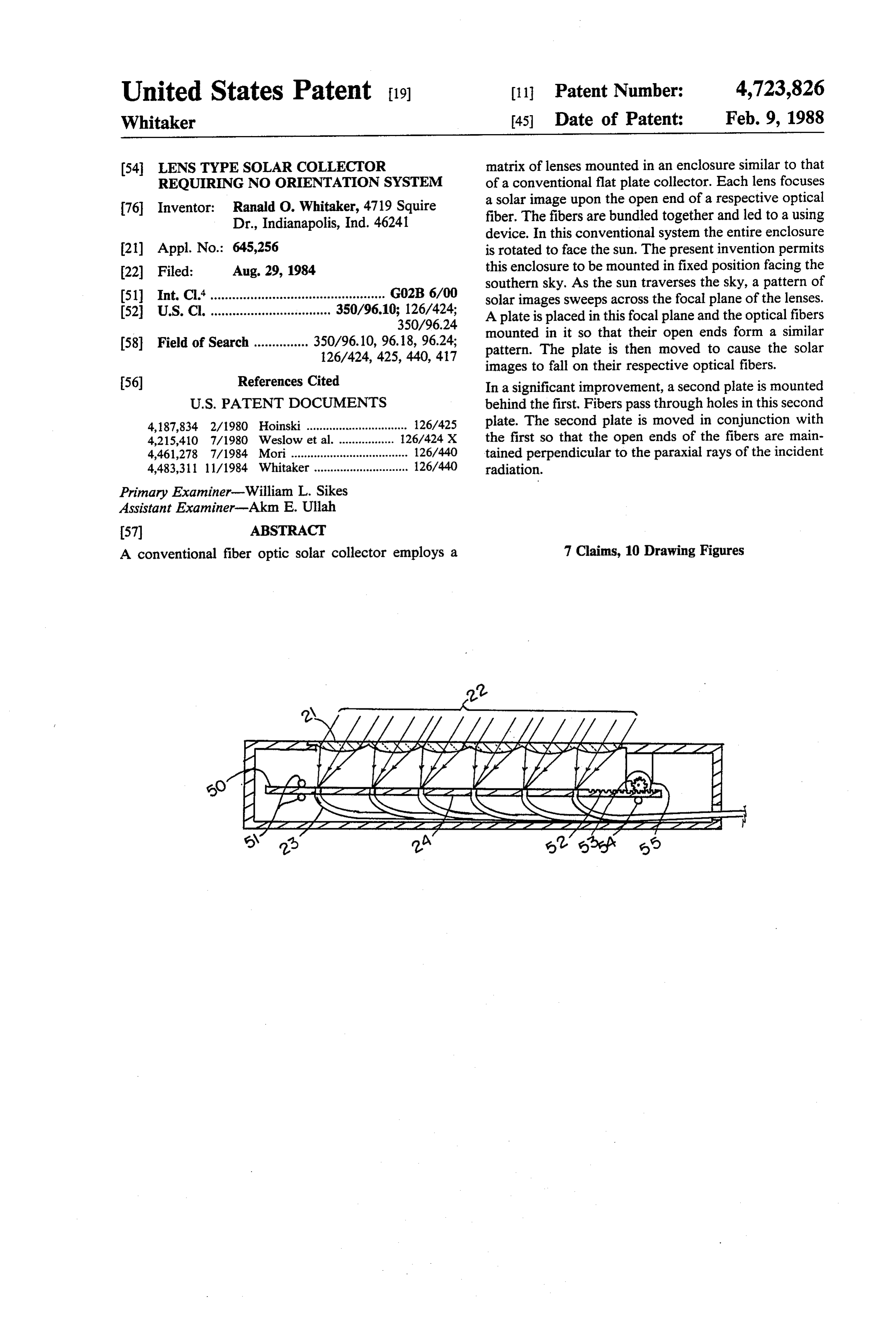
United States Patent (19) 11 Patent Number: 4,723,826 Whitaker (45. Date of Patent: Feb. 9, 1988 (54 LENS TYPESOLAR COLLECTOR matrix of lenses mounted in an enclosure similar to that REQUIRING NO ORIENTATION SYSTEM of a conventional flat plate collector. Each lens focuses 76 Inventor: Ranald O. Whitaker, 4719 Squire a solar image upon the open end of a respective optical Dr., Indianapolis, Ind. 46241 fiber. The fibers are bundled together and led to a using device. In this conventional system the entire enclosure 21) Appl. No.: 645,256 is rotated to face the sun. The present invention permits 22 Filed: Aug. 29, 1984 this enclosure to be mounted in fixed position facing the southern sky. As the sun traverses the sky, a pattern of 51) Int. Cl."................................................ GO2B 6/00 solar images sweeps across the focal plane of the lenses. 52 U.S.C. ................................. 350/96.10; 126/424; A plate is placed in this focal plane and the optical fibers
(58) Field of Search............... 350/96.10, 96.18, 96.24; mounted in it so that their open ends form a similar 126/424, 425, 440, 417 pattern. The plate is then moved to cause the solar images to fall on their respective optical fibers.
56) References Cited In a significant improvement, a second plate is mounted
4,187,834 2/1980 Hoinski ............................... 126/425 plate. The second plate is moved in conjunction with 4,215,410 7/1980 Weslow et al. 26/424 X the first so that the open ends of the fibers are main 4,461,278 7/1984 Mori .................................... 126/440 tained perpendicular to the paraxial rays of the incident 4,483,311 11/1984 Whitaker ............................. 126/440 radiation.
Primary Examiner-William L. Sikes
Assistant Examiner-Akm E. Ullah
A conventional fiber optic solar collector employs a 7 Claims, 10 Drawing Figures
372 SSSSSSA is Rover capital
Page 2
Drawing sheet — no readable text.
Page 3
Drawing sheet — no readable text.
Page 4
Drawing sheet — no readable text.
Page 5
Drawing sheet — no readable text.
Page 6
of lenses 21 faces the sun. Solar radiation 22 passes
LENS TYPE SOLAR COLLECTOR REQUIRING through lenses 21 and forms solar images on the open NO ORIENTATION SYSTEM ends of optical fibers 23. Optical fibers 23 are bundled together and led to a using system such as a hot water
CROSS REFERENCES TO RELATED 5 heater.
APPLICATIONS A significant feature of this system is that there is no There are no related applications. Consequently, conduction loss to the surrounding air. The heat which there are no cross references. this system delivers is a function of the solar radiation STATEMENT AS TO RIGHTS TO INVENTIONS 10 impinging on the collector and that only. Consequently
MADE UNDER FEDERALLY SPONSORED it can deliver as much heat on the coldest day of winter RESEARCH AND DEVELOPMENT (IF ANY) as it does on the hottest day of summer. This is in stark contrast to the conventional flat plate collector-which
This invention was not made under Federally spon can deliver no heat on the coldest day of winter when sored research and development. Consequently there is 15 that heat is needed most.
no statement regarding such rights. A second significant feature is that heat can be deliv BACKGROUND OF THE INVENTION ered at high temperature. It can be shown that the theo 1. Field of the Invention. retical limit is the temperature of the surface of the This invention is in the field of solar collectors. sun-some 6,000 K. This can be achieved by operating 20 the system outside the atmosphere, using lossless mate 2. Description of the Prior Art.
Whitaker (App. No. 06/521,491 Filed 10/09/79) dis rials, and using an absorber such as that described in cusses a solar collector using a matrix of lenses and a set Whitaker U.S. Pat. No. 3,234,931. of optical fibers, each lens focusing solar radiation upon A third significant feature is that an orientation sys a respective optical fiber. The entire array of lenses is 25 tem is required. It must turn the entire array to face the oriented to face the sum. Consequently each solar image sun. Orientation systems are available but they are trou is kept on the optical axis of its respective lens at all ble prone and costly. This is especially true in location times. where storms are common.
Diner (U.S. Pat. No. 4,201,197) discusses a similar SUMMARY OF THE INVENTION system, using one large lens focusing upon the open end
A frame similar to that of a conventional flat plate
Bowers (U.S. Pat. No. 4,282,858 filed 3/27/80) dis collector is placed in fixed position facing generally cusses a similar system to that of Whitaker. toward the sun. The front of the collector consists of a The French and Japanese are both working signifi matrix of lenses each about 10 cm square-or hexago cantly in this field. No publications are presently on nal. This invention provides a set of optical fibers the
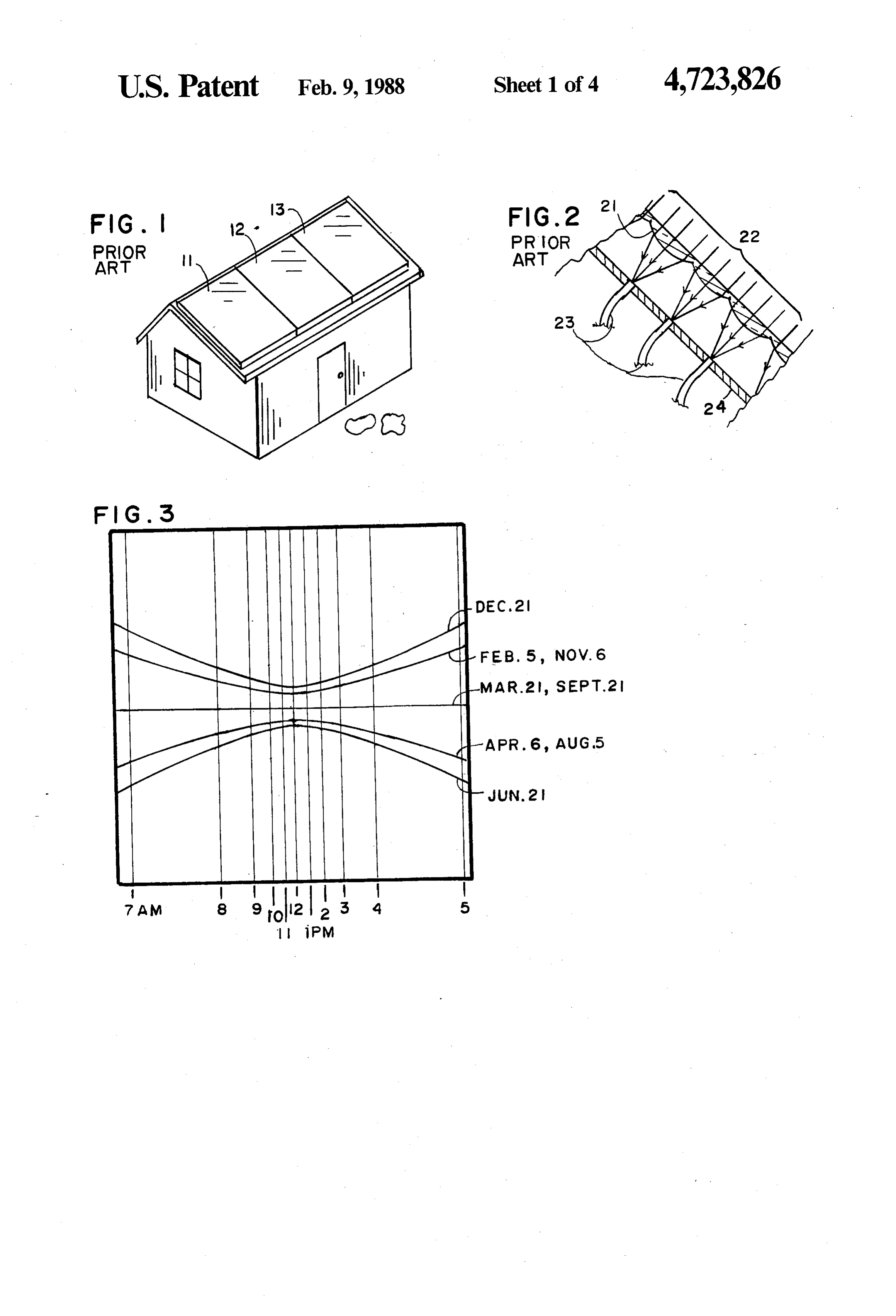
Pertinent details regarding flat plate collectors and open end of each of which fibers is kept in position to the Whitaker system will next be discussed. receive a respective one of these solar images. This A typical installation of conventional flat plate solar result is obtained by placing a "positioning' plate in the collectors is shown in FIG.1. The collectors 11, 12, and focal plane of the lenses. The open ends of the optical 13 are placed on a south-facing roof. Solar radiation fibers terminate in this plate, forming a pattern identical passes through the glass plate with which each collector to that of the solar images. A servo system moves the is covered. Within the collector this radiation is ab plate to keep the open ends of the optical fibers each sorbed on a blacken surface and turned into sensible under its respective solar image. In an alternate system heat. A portion of this heat passes to a working fluid a computer is used to position the plate. circulated through the collector and is by that fluid 45 The axis of the open end of each optical fiber should carried to a using device (such as a hot water heater) face the incident radiation. To accomplish this desired inside the house. A second portion is lost by conduction result, the basic system is modified to provide an "orien back up through the glass to the ambient air. As the tation' plate on the fiber side of the positioning plate. ambient temperature drops, this loss becomes excessive. The orientation plate bears a pattern of holes similar to A typical collector will lose half the collected energy 50 those of the positioning plate. Pivots through which the via this conduction when the outside temperature drops optical fibers pass are placed in both plates. The motors to 273 K (freezing). Consequently conventional flat which move the positioning plate also move the orienta plate collectors are useful for heating water and homes tion plate-but at a faster rate. This keeps the fibers only in temperate or tropic climates.
A second significant feature of the flat plate collector 55 facing the impinging radiation.
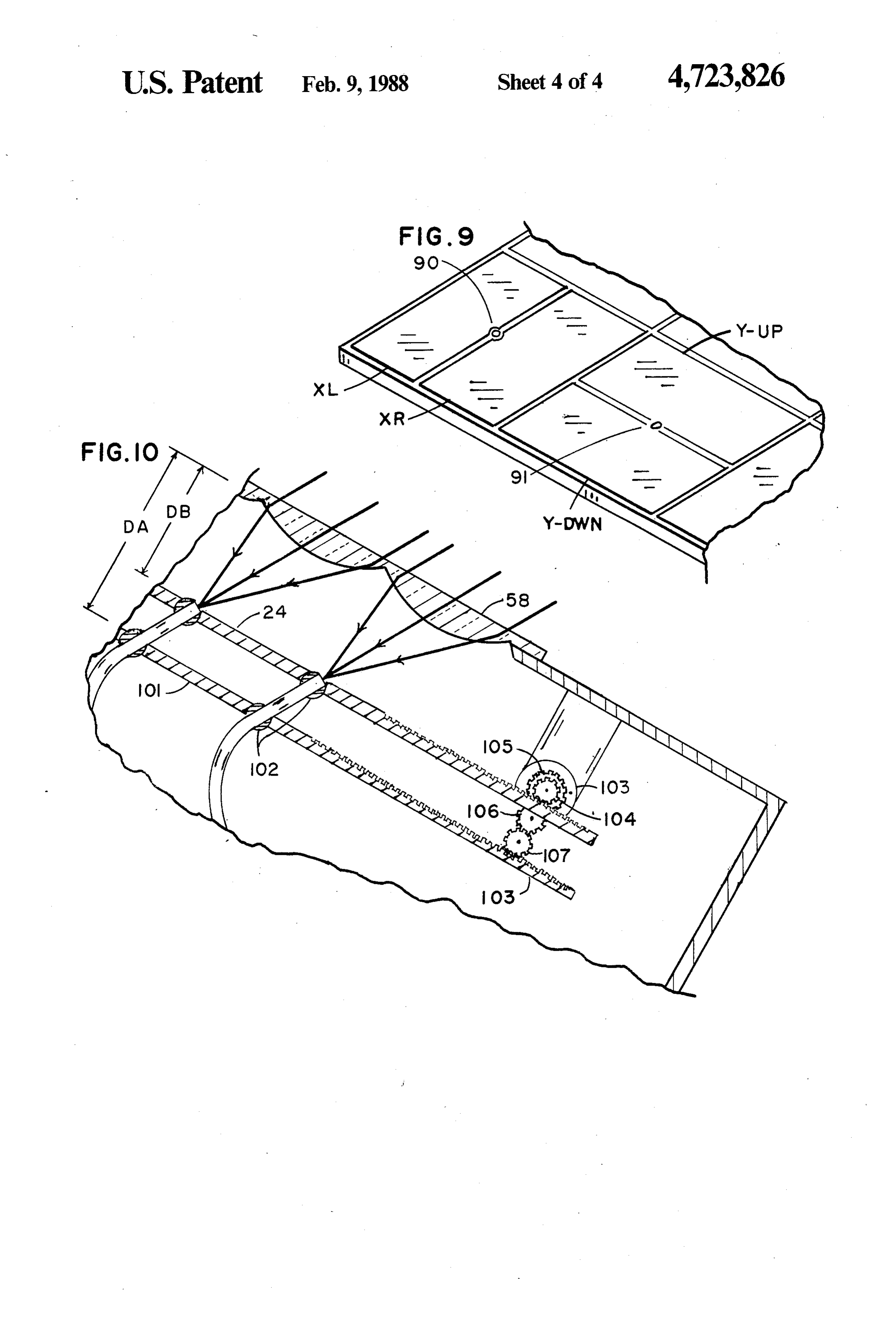
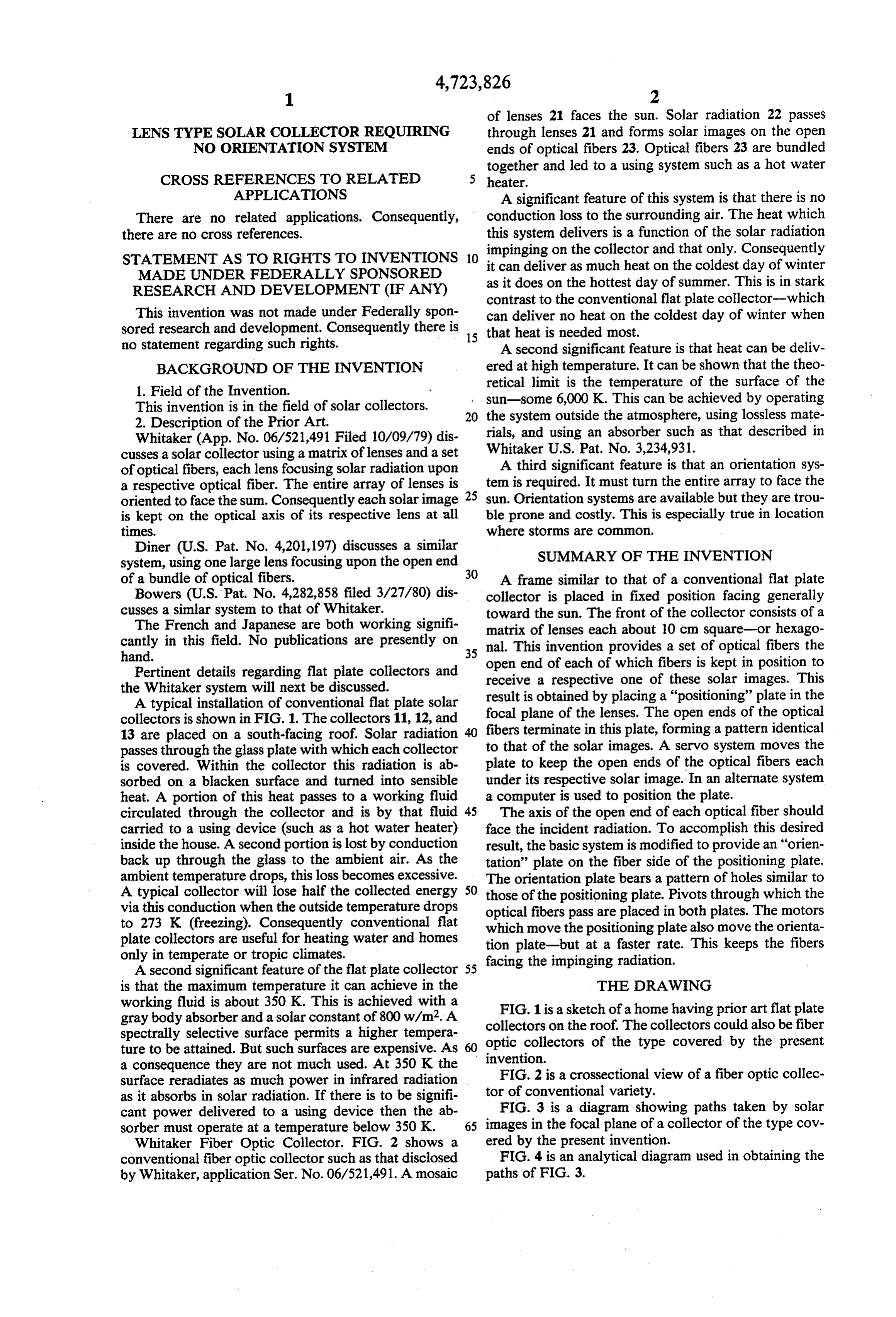
is that the maximum temperature it can achieve in the THE DRAWING working fluid is about 350 K. This is achieved with a FIG. 1 is a sketch of a home having prior art flat plate gray body absorber and a solar constant of 800 w/m2. A collectors on the roof. The collectors could also be fiber spectrally selective surface permits a higher tempera optic collectors of the type covered by the present ture to be attained. But such surfaces are expensive. As invention.
a consequence they are not much used. At 350 K the surface reradiates as much power in infrared radiation FIG. 2 is a crossectional view of a fiber optic collec as it absorbs in solar radiation. If there is to be signifi torFIG.of conventional variety.
3 is a diagram showing paths taken by solar cant power delivered to a using device then the ab sorber must operate at a temperature below 350 K. 65 images in the focal plane of a collector of the type cov Whitaker Fiber Optic Collector. FIG. 2 shows a ered by the present invention.
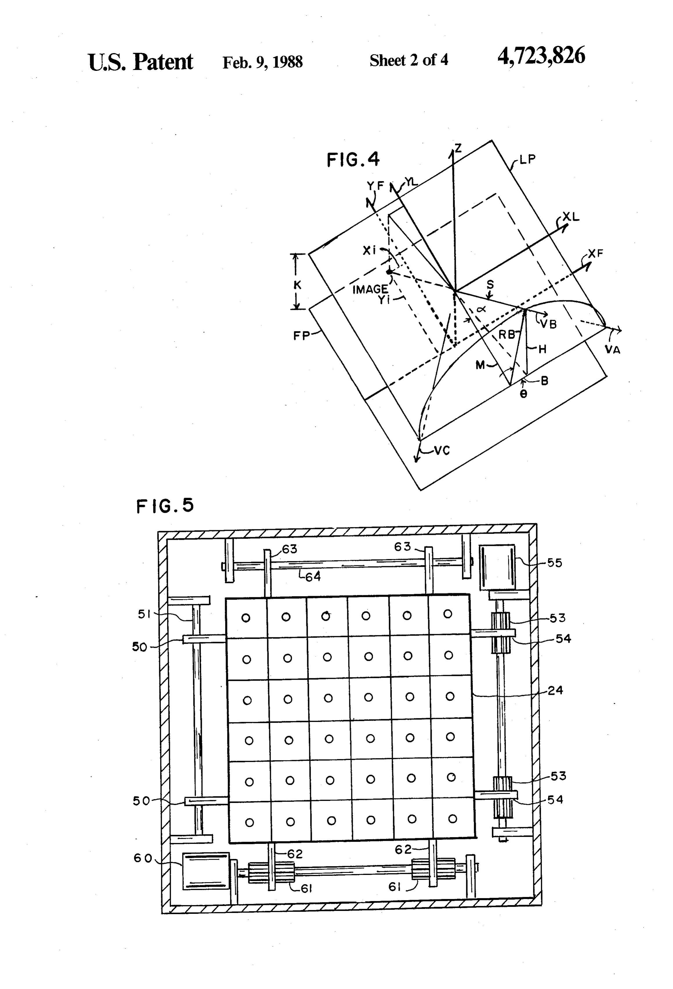
conventional fiber optic collector such as that disclosed FIG. 4 is an analytical diagram used in obtaining the by Whitaker, application Ser. No. 06/521,491. A mosaic paths of FIG. 3.
Page 7
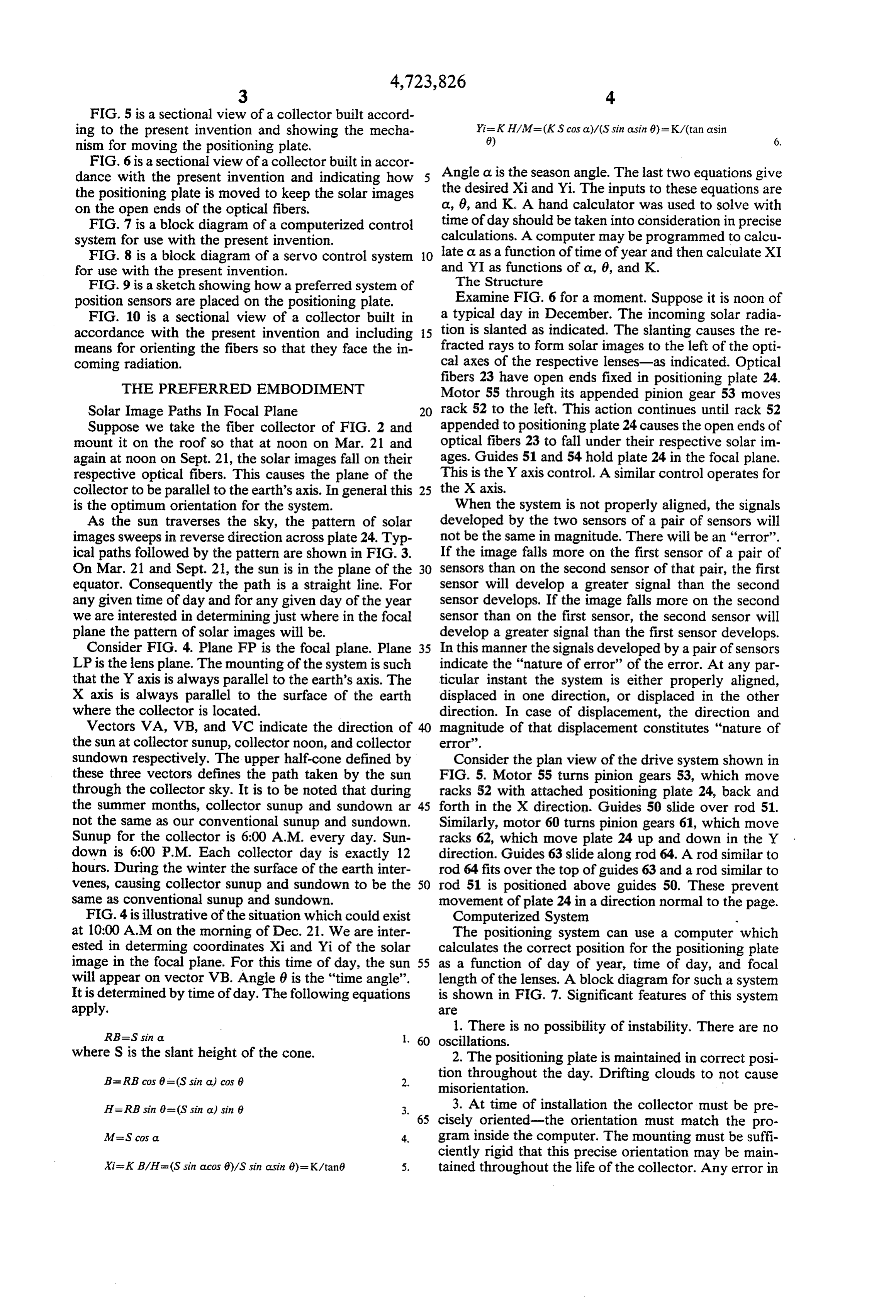
FIG. 5 is a sectional view of a collector built accord ing to the present invention and showing the mecha Yi-K H/M=(KS cosa)/(S sin a sin 0) = K/(tanasin
nism for moving the positioning plate.
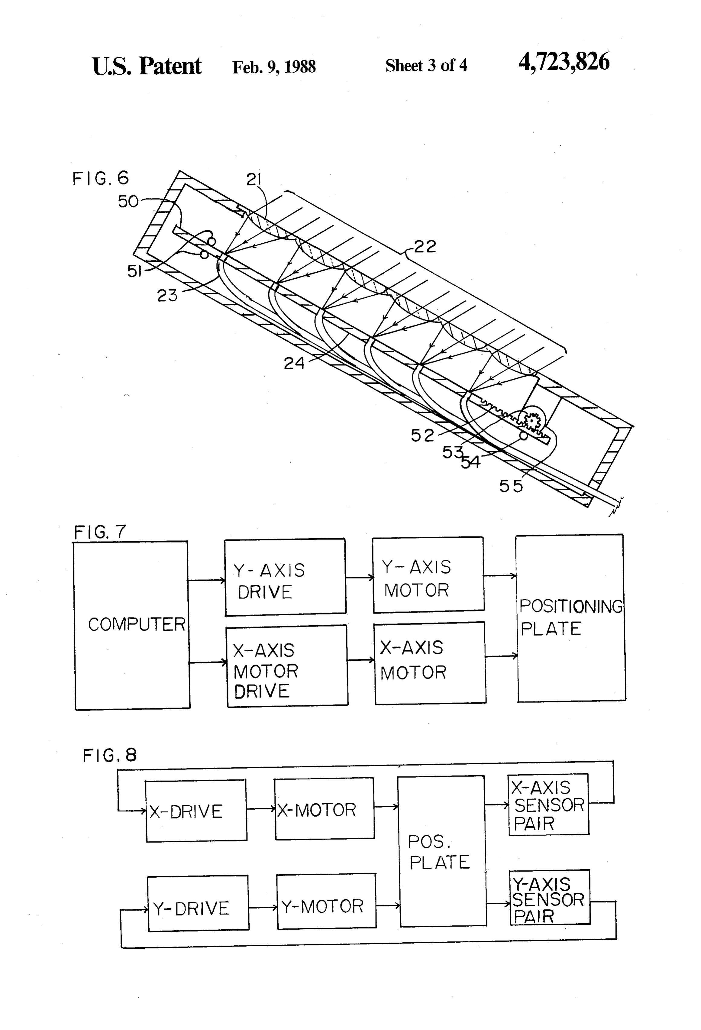
FIG. 6 is a sectional view of a collector built in accor dance with the present invention and indicating how 5 Angle a is the season angle. The last two equations give the positioning plate is moved to keep the solar images the desired Xi and Yi. The inputs to these equations are on the open ends of the optical fibers. o, 6, and K. A hand calculator was used to solve with FIG. 7 is a block diagram of a computerized control time of day should be taken into consideration in precise system for use with the present invention. calculations. A computer may be programmed to calcu FIG. 8 is a block diagram of a servo control system 10 late a. as a function of time of year and then calculate XI for use with the present invention. and YI as functions of a, 6, and K. FIG. 9 is a sketch showing how a preferred system of The Structure position sensors are placed on the positioning plate. Examine FIG. 6 for a moment. Suppose it is noon of FIG. 10 is a sectional view of a collector built in a typical day in December. The incoming solar radia accordance with the present invention and including 15 tion is slanted as indicated. The slanting causes the re means for orienting the fibers so that they face the in fracted rays to form solar images to the left of the opti coming radiation. cal axes of the respective lenses-as indicated. Optical fibers 23 have open ends fixed in positioning plate 24.
THE PREFERRED EMBODIMENT Motor 55 through its appended pinion gear 53 moves Solar Image Paths. In Focal Plane 20 rack 52 to the left. This action continues until rack 52 Suppose we take the fiber collector of FIG. 2 and appended to positioning plate 24 causes the open ends of mount it on the roof so that at noon on Mar. 21 and optical fibers 23 to fall under their respective solar im again at noon on Sept. 21, the solar images fall on their ages. Guides 51 and 54 hold plate 24 in the focal plane. respective optical fibers. This causes the plane of the This is the Y axis control. A similar control operates for collector to be parallel to the earth's axis. In general this 25 the X axis.
is the optimum orientation for the system. When the system is not properly aligned, the signals As the sun traverses the sky, the pattern of solar developed by the two sensors of a pair of sensors will images sweeps in reverse direction across plate 24. Typ not be the same in magnitude. There will be an "error'. ical paths followed by the pattern are shown in FIG. 3. If the image falls more on the first sensor of a pair of On Mar. 21 and Sept. 21, the sun is in the plane of the 30 sensors than on the second sensor of that pair, the first equator. Consequently the path is a straight line. For sensor will develop a greater signal than the second any given time of day and for any given day of the year sensor develops. If the image falls more on the second we are interested in determining just where in the focal sensor than on the first sensor, the second sensor will plane the pattern of solar images will be. develop a greater signal than the first sensor develops. Consider FIG. 4. Plane FP is the focal plane. Plane 35 In this manner the signals developed by a pair of sensors LP is the lens plane. The mounting of the system is such indicate the "nature of error' of the error. At any par that the Y axis is always parallel to the earth's axis. The ticular instant the system is either properly aligned, X axis is always parallel to the surface of the earth displaced in one direction, or displaced in the other where the collector is located. direction. In case of displacement, the direction and Vectors VA, VB, and VC indicate the direction of 40 magnitude of that displacement constitutes "nature of the sun at collector sunup, collector noon, and collector error'.
sundown respectively. The upper half-cone defined by Consider the plan view of the drive system shown in these three vectors defines the path taken by the sun FIG. 5. Motor 55 turns pinion gears 53, which move through the collector sky. It is to be noted that during racks 52 with attached positioning plate 24, back and the summer months, collector sunup and sundown ar 45 forth in the X direction. Guides 50 slide over rod 51. not the same as our conventional sunup and sundown. Similarly, motor 60 turns pinion gears 61, which move Sunup for the collector is 6:00 A.M. every day. Sun racks 62, which move plate 24 up and down in the Y down is 6:00 P.M. Each collector day is exactly 12 direction. Guides 63 slide along rod 64. A rod similar to hours. During the winter the surface of the earth inter rod 64 fits over the top of guides 63 and a rod similar to venes, causing collector sunup and sundown to be the 50 rod 51 is positioned above guides 50. These prevent same as conventional sunup and sundown. movement of plate 24 in a direction normal to the page. FIG. 4 is illustrative of the situation which could exist Computerized System at 10:00 A.M. on the morning of Dec. 21. We are inter The positioning system can use a computer which ested in determing coordinates Xi and Yi of the solar calculates the correct position for the positioning plate image in the focal plane. For this time of day, the sun 55 as a function of day of year, time of day, and focal will appear on vector VB. Angle 6 is the "time angle". length of the lenses. A block diagram for such a system It is determined by time of day. The following equations is shown in FIG. 7. Significant features of this system apply. 3.
RB=S sin a 1. There is no possibility of instability. There are no i. 60 oscillations.
where S is the slant height of the cone. 2. The positioning plate is maintained in correct posi B= RB cos 8=(S sin a) cos 0 2. tion throughout the day. Drifting clouds to not cause misorientation.
H= RB sin 8=(S sin a) sin 8 3. 3. At time of installation the collector must be pre 65 cisely oriented-the orientation must match the pro
M=S cos a 4. gram inside the computer. The mounting must be suffi ciently rigid that this precise orientation may be main
Xi=KB/H=(S sin acos 0)/S sin a sin 6)=K/tané 5. tained throughout the life of the collector. Any error in
Page 8
orientation which develops will cause the solar images the paraxial ray to be perpendicular to the open end of to move from the optical fibers. The computer will the optical fiber. The paraxial ray is defined as the ray maintain this error, rather than correct it. coming from the center of the solar disc. Servo Drive System COMPARISON OF PRESENT SYSTEM WITH A An alternate servo drive system is diagrammed in CONVENTIONAL FIBER OPTIC SYSTEM FIG.8. The Ysensor senses when an error along the Y axis exists and feeds a signal to the Y axis drive which In the conventional system (See Whitaker, applica causes this error to be reduced to zero. The action is tion Ser. No. 06/521,491) the plate holding the optical similar for the X axis. A preferred sensor system is fibers does not move relative to the lens matrix. It keeps illustrated in FIG. 9. Four sensors are mounted on one 10 each optical fiber on the optical axis of its respective corner of the positioning plate. Sensors XR and XL are lens. The entire collector is turned to face the sun. The placed around optical fiber 90 as shown. When the solar following are significant:
image is correctly positioned on the open end of optical 1. The system can be used from conventional sunup fiber 90, the two sensors will receive equal amounts of to sundown during the summer. About fifteen hours. the stray radiation appearing at the edge of the solar 15 The present system can be used only during the twelve image. If the solar image is displaced to the right, sensor hours centered about noon. Toward the limits of this XR will receive more than sensor XL. period the solar spot becomes excessively large and If the solar image is displaced to the left-XL will traverse required of the positioning system becomes receive more than XR. Sensors XR and XL are prefera excessive. This limits the effective period to no more bly silicon solar cells. Each develops an electrical out 20 than 10 hours. During winter the effective period is less put proportional to the light falling upon it. The differ than this.
ence in these two outputs is used to casue the X axis 2. The conventional system causes the collector to driver to act to move the positioning place so that the face the sun at all times. The amount of solar radiation error is brought to zero. The Y axis control operates in impinging on the collector is not reduced according to similar manner, using sensors YUP and YDWN posi 25 the cosine law. For the current system the solar radia tioned around fiber 91. Significant features of this sys tion impinging upon the collector is reduced by the ten are: cosine law. This further reduces the effective hours of 1. Instabilities may develop. This problem arises with the current collector. During summer it will be effec every closed loop system. tive from 8:00 A.M until 4:00 P.M. During winter, from 2. Passing clouds disturb the system. Cause the sys 30 9:00 A.M. until 3:00 P.M.
tem to jig and job. Bending the optical fibers and wear 3. The one great advantage of the current system ing out the mechnical parts. These jigs and jogs may be over the conventional system is that it is mounted fixed reduced by slowing the response of the control loops. to the supporting structure. This large collector con 3. Independent control must be provided to cause the taining the matrix of lenses is not swinging around in the system to face the sun at sunup. 35 open inviting the next strong wind to provide it free 4. The chief advantage of this system over the com transportation into the next county.
puter system is that small errors caused by frame war GENERAL COMMENTS page or freezing of the ground on which the system is mounted-are corrected by the servo system. 1. The lens structure depicted in FIG. 2 and subse
ALIGNING THE FIBERS TO THE INCOMING
quent figures facilitates cleaning of the outer surface.
Since the lens surface is inside and the outer surface is
RADIATION flat, the latter may be covered with a plastic sheet of The maximum possible amount of radiation enters the essentially the same index of refraction as the lens mate fiber when the solar radiation is normal to the fiber. rial. The contacting surface may be wiped with a fluid During early morning and late evening the radiation 45 to cause close adherence. When the sheet becomes comes in at a considerable slant. It is the nature of the dirty, it may be whisked off and a new one put on. open end of the optical fiber that as the slat at which 2. The plates may be replaced by a wire framework. radiation strikes the fiber increases, more of it is re 3. Several alternate pivotal mechanisms may be used flected and less accepted. Also, there is a critical angle in place of those depicted in FIG. 10. beyond which no radiation will be transmitted down 50 4. The pinion and rack drive system may be replaced the fiber. Consequently the system of FIG. 2 can oper by one of several alternate systems. Such as a hydraulic ate effectively from about 9:00 in the morning until 3:00 drive involving a piston.
in the afternoon. This period may be extended if means 5. The sensor system of FIG. 9 is suggestive only. is provided for turning the optical fibers so that they Several alternate systems may be used. always face the incoming radiation. 55 6. In the preferred system the collector is positioned Means for accomplishing this for the X axis is illus so that the plane of the lenses is normal to solar radia trated in FIG. 10. An orientation plate 101 is placed tion at noon on the 21st of March and again on the 21st under positioning plate 24. Pivots 102 for holding the of September. However, the conditions of particular fibers are placed in both plates. The X motor 103 turns installations and the requirements of those installations pinion 104, moving positioning plate 24. Motor 103 also may make it desirable to depart from this orientation. turns pinion gear 105-which turns gear 106, which For instance, should there be general cloud cover dur turns gear 107, which moves orientation plate 101. The ing the summer months, then the collector should be ratio of pitch diameter of gear 104 to pitch diameter of tilted so that it faces the winter sun-to increase effec gear 105 is equal to the ratio of da to db. As far as the X tiveness of collection during the winter. Likewise, if the axis is concerned, this causes the ends of optical fibers to 65 system is used strictly for space heating in winter, the face the centers of their respective lenses. collector should be tilted to face the winter sun. But if A similar system causes the fibers to face the centers the cloud cover is in winter and the system is used to of the lenses as far as the Y axis is concerned-causes generate power for operating an air conditioner, then
Page 9
the collector should be tilted more toward the summer said Y direction being perpendicular to said X direction sun. If there is cloud cover in the mornings but not in and also lying in the plane of said plate; the afternoons-the collector should be turned toward said X drive including a pair of X photoelectric sen the west. sors, an X amplifier, and an X motor; 6. Convex lenses have been shown in the several 5 said X pair of photoelectric sensors being mounted on figures. Fresnel lenses may be used. Fresnel lenses said plate and adapted for developing an X set of would reduce the amount of lens material required. electrical signals indicating magnitude and direc However, there is a loss associated with the serrations. tion of error in positioning of said plate in the X In most applicatios the additional mass of the lens mate direction;
rial used in the convex lenses is not sufficient to justify 10 said X amplifier being adapted in response to said X the loss associated with the Fresnel lenses. electrical signals for delivering an X drive signal; 7. The radiation delivered by the system is capable of said X motor being adapted in response to said X generating high temperatures. The radiation may be drive signal for moving said positioning plate in delivered to a stove for cooking means. It may be used that X direction which will reduce the X position to provide heat to a steam engine. It may be used to 15 ing error to zero; and light interior rooms and light factories. In the last appli said Y drive being similarly composed to said X drive cation the broad spectrum of solar radiation provides and performing a service in said Y direction similar better "seeability” than do sharp line spectra such as to that performed by said X drive in said X direc that provided by fluroescent tubs. tion.
8. Care must be exercised in selection of optical fibers. 20 3. A system for collecting solar power as in claim 1; Excessive attenuation within the fibers causes unwanted losses and heats the bundled fibers to excessive tempera said positioning means being a bi-axial drive compris tures. DuPont provides a plastic fiber (Crofon) which is ing a computer; an X drive for positioning said 1 mm in diameter and has losses permitting it to be used plate in the X direction and a Y drive for position for distances of a few meters. The material is inexpen 25 ing said plate in the Y direction, said X direction sive. Glass fibers from one of several sources have very lying in the plane of said plate and said Y direction low attenuation-permitting them to be used for dis being perpendicular to said X direction and also tances up to 1 km. However, diameters are low and cost lying in the plane of said plate; is high. At present there is no market for large diameter said X drive, in response to electrical signals received low-loss fibers. As this market develops, appropriate 30 from said computer, being adapted for moving said materials will become available. plate in the X direction; 9. The preferred material for the lenses is molded said Y drive being adapted in response to electrical plastic. However, glass lenses may be used. Transpar signals received from said computer for moving ency to solar radiation is the only requirement. Quality said plate in the Y direction; and of lenses must be higher than that for lenses used in 35 said computer being modified by a computer pro conventional systems (such as that of Whitaker dis gram, said modification adapting said computer for cussed previously) since the former must focus sharply generation of said electrical signals. over an appreciable portion of the focal plane while the 4. A system for collecting solar power as in claim 2; latter must focus sharply only on the optical axis. said solar power having associated with its solar radi I claim: 40 ation having a paraxial solar ray; 1. A stationary solar collector system for collecting said system including means for orienting each of said solar radiation from the sun; optical fibers so that the open end of each of said said system comprising means, including a matrix of optical fibers is approximately perpendicular to lenses, for focusing solar radiation onto a focal said paraxial solar ray delivered to said open end by plane to form a set of solar images in said plane; 45 said respective lens;
a set of optical fibers, each of said fibers having an said orienting means including an orientation plate open end; placed on the fiber side of said positioning plate and a positioning plate holding said open ends of said bearing a pattern of holes whose configuration is fibers within a common plane which is coincident congruent to said solar image configuration; with said focal plane; and 50 said X motor having gearing operatively associated positioning means for moving said plate laterally with said X motor and said orientation plate for relative to said matrix of lenses, said optical fibers driving said orientation plate in the X direction and being substantially equal in number to the number said Y motor having gearing operatively associated of lenses in said matrix and positioned within said with said Y motor and said orientation plate for plate with said open ends being in the same pattern 55 driving said orientation plate in the Y direction; or configuration as the lenses in said matrix and and such that each open end is at the focal point of a the gearing ratios of said gearing being selected to corresponding lens in said matrix, said positioning cause said orientation plate to move to keep the means moving said plate laterally relative to said axes of the open ends of the said optical in align matrix of lenses in such manner that said pattern of 60 ment with respective paraxial rays. open ends of said fibers can always be made to 5. A system as in claim 4;
coincide with said pattern of solar images as the sun each of said holes in said orientation plate and each of traverses the solar collector. said holes in said positioning plate bearing a respec 2. A system for collecting solar power as in claim 1; tive pivot member rotatably mounted in said hole; said positioning means being a biaxial drive comprising 65 and an X drive for positioning said plate in the X direction each of said pivot members bearing a hole through and a Y drive for positioning said plate in the Y direc which a respective fiber passes. tion; said X direction lying the plane of said plate and 6. A system for collecting solar power as in claim 3;
Page 10
said solar power having associated with it solar radia with said Y motor and said orientation plate for tion having a paraxial solar ray; driving said orientation plate in the Y direction; said system including means for orienting each of said and optical fibers so that the open end of each of said the gearing ratios of said gearing being selected to optical fibers is approximately perpendicular to cause said orientation plate to move to keep the said paraxial solar ray delivered to said open end by axes of the open ends of said optical in alignment said respective lens; with respective paraxial rays. said orienting means including an orientation plate 7. A system for collecting solar power as in claim 6; placed on the fiber side of said positioning plate and each of said holes in said orientation plate and each of bearing a pattern of holes whose configuration is 10 said holes in said positioning plate bearing a respec congruent to said solar image configuration; tive pivot member rotatably mounted in said hole; said X motor having gearing operatively associated and with said X motor and said orientation plate for each of said pivot members bearing a hole through driving said orientation plate in the X direction and which a respective
fiber passes.
said Y motor having gearing operatively associated 15
Page 11
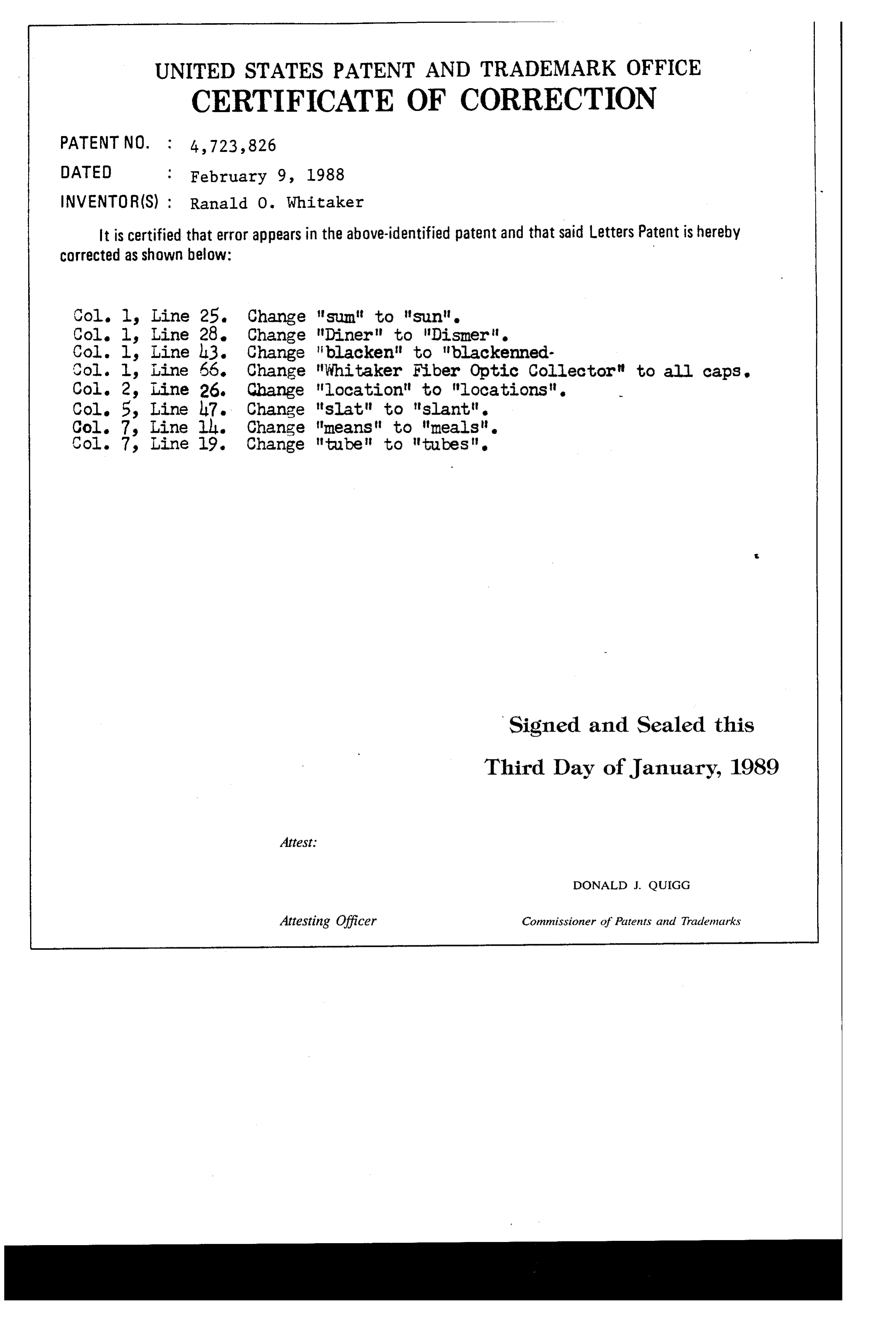
UNITED STATES PATENT AND TRADEMARK OFFICE
CERTIFICATE OF CORRECTION
INVENTOR (S) : Ranald O. Whitaker
It is certified that error appears in the above-identified patent and that said Letters Patent is hereby Corrected as shown below:
Col. 1, Line 28. Change "Diner to Disner it. Col. l. Line l3. Change "blacken" to "blackenned Col. l, Line 66. Change "Whitaker Fiber Optic Collector it to all caps. Col. 2, Line 26. Change "location" to "locations. Col. 5, Line l7. Change "slat" to "slantt. Col. 7, Line ill. Change means to meals Col. 7, Line 19. Change tube to tubest
Signed and Sealed this
Third Day of January, 1989
Attest.
DONALD J. QUIGG
Attesting Officer Commissioner of Patents and Trademarks
Provenance
- Collection
- Cited prior art
- Original PDF
- patentimages.storage.googleapis.com →
- Filed
- 1984-08-29
- Pages
- 11
- Method
- pdftotext (the PDF's own text layer) + pdftoppm 300dpi page scans
- Source
- Google Patents bibliographic record
- Granted
- 1988-02-09
- Inventors
- Ranald O. Whitaker
- Transcribed from
- patentimages.storage.googleapis.com →