patent · US4798444
Solar collection device
17 January 1989
Page 1 — bibliographic record
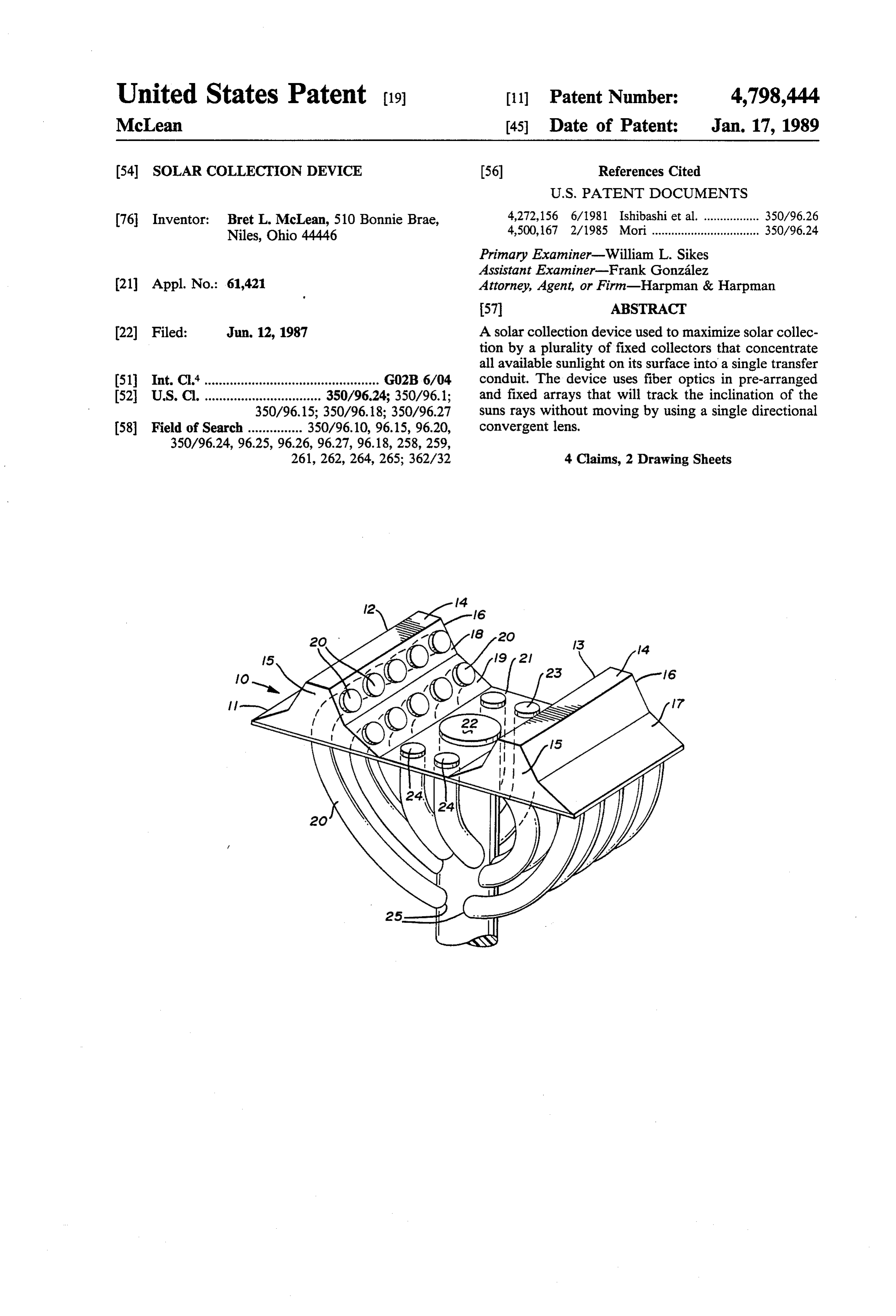
United States Patent (19) 11 Patent Number: 4,798,444 McLean 45 Date of Patent: Jan. 17, 1989 (54. SOLAR COLLECTION DEVICE (56) References Cited
76 Inventor: Bret L. McLean, 510 Bonnie Brae, 4,272,156 6/1981 Ishibashi et al. ................. 350/96.26 Niles, Ohio 44446 4,500,167 2/1985 Mori................................. 350/96.24 Primary Examiner-William L. Sikes
Assistant Examiner-Frank González 21 Appl. No.: 61,421 Attorney, Agent, or Firm-Harpman & Harpman
22 Filed: Jun. 12, 1987 A solar collection device used to maximize solar collec tion by a plurality of fixed collectors that concentrate all available sunlight on its surface into a single transfer 511 Int. Cl*................................................ GO2B6/04 conduit. The device uses fiber optics in pre-arranged 52 U.S. Cl. ................................ 350/96.24; 350/96.1; and fixed arrays that will track the inclination of the 350/96.15; 350/96.18; 350/96.27 suns rays without moving by using a single directional 58 Field of Search ............... 350/96.10, 96.15, 96.20, convergent lens.
261, 262, 264, 265; 362/32 4 Claims, 2 Drawing Sheets
Page 2
Drawing sheet — no readable text.
Page 3
Drawing sheet — no readable text.
Page 4
angularly positioned panels 18 and 19 each having a
SOLAR COLLECTION DEVICE different relative alignment.
A plurality of fiber optic bundles 20 are positioned in
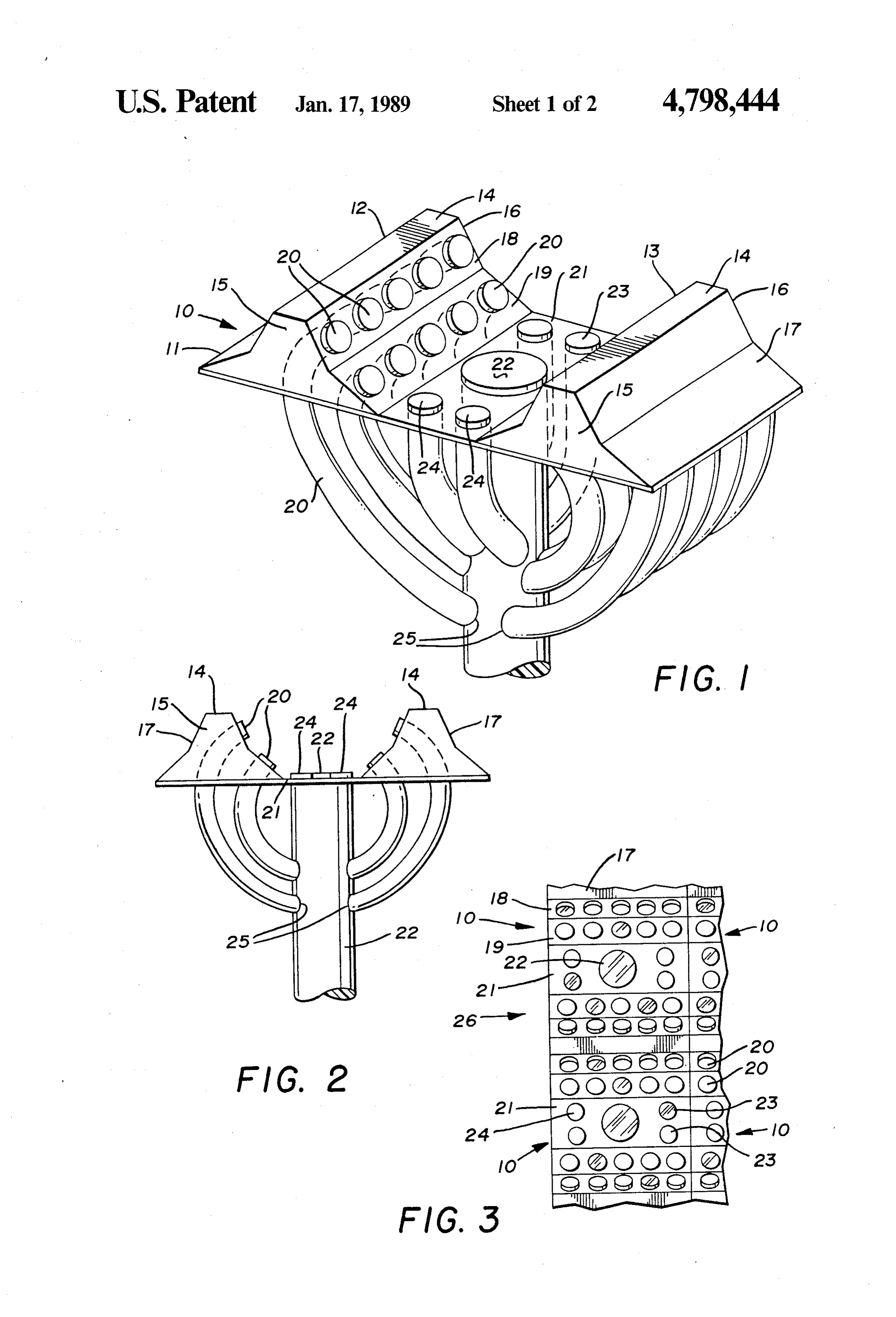
BACKGROUND OF THE INVENTION each of the panels 18 and 19 in spaced longitudinally 1. Technical Field aligned relation to one another and in oppositely dis This invention relates to solar light collection systems posed aligned relation between said panels. that use solar energy as a light source and transfer that Each of the upstanding portions 12 and 13 with its light via fiber optic cables. associated fiber optic bundles are spaced in relation to 2. Description of Prior Art one another by a main support plate 21 having a cen Prior Art devices of this type have relied on a variety O trally positioned large diameter fiber optic bundle 22. Pairs of secondary fiber optic bundles 23 and 24 are of different collection configurations with primary emi positioned phasis on concentrating and directing the solar light. dle 22 all ofonwhich either side of said central fiber optic bun are aligned co-planar with the sup
Sun tracking devices have been developed to adjust the port plate 21.
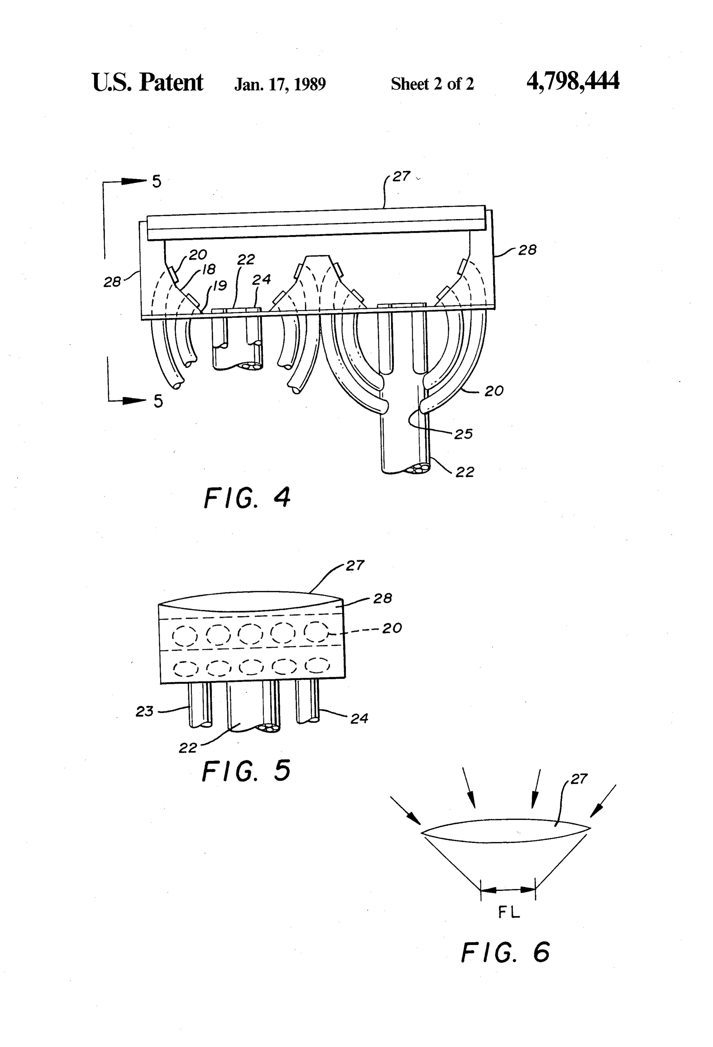
collectors to the varying angular inclination of the suns 15 The fiber optic bundles 20 and secondary fiber optic track during the day which varies due to the earths bundles 23 and 24 extend away and downwardly from rotation and the seasonal variations, see for example their respective sun engagement ends and intersect with U.S. Pat. No. 4,297,000, U.S. Pat. No. 4,511,755, U.S. the larger diameter fiber optic bundle 22 annularly on Pat. No. 4,152,752 and U.S. Pat. No. 3,51,559. the outer surface of same at 25. In U.S. Pat. No. 4,297,000 a solar lighting system is 20 Referring to FIGS. 4 and 5 of the drawings a typical disclosed that uses a solar collector and a tracking multiple array 26 of the solar collectors 10 is disclosed mechanism. The collector is a parabolic mirror to con wherein two of the collectors are mounted together centrate the solar light on a fiber optic bundle that ex with extended vertical side wall portions 28. A continu tends into the building. Various fiber bundles are then ous and contoured lip 29 is formed on the respective branched off to illuminate distant interior areas. 25 side wall portions 28 to hold and support a convergent In U.S. Pat. No. 4,511,755 a solar collection apparatus single directional lens 27 therebetween extending over is disclosed wherein a plurality of lenses are mounted in two of the solar collectors 10.
spaced parallel relation to their respective focal points Referring to FIG. 6 of the drawings, the convergent which are pigtails to gather the concentrated solar light lens 27 is illustrated in graphic form with the angle of and direct same for use. 30 sun inclination illustrated and corresponding area of U.S. Pat. No. 4,152,752 discloses an illumination sys multiple focal points FL during the daylight hours as tem having a central collector and a network of light the relative angle of the sun on the collectors changes. pipes to direct light to outlet fixtures controlled by light The use of convergent lens 27 effectively tracks the switches and variable light transmission devices. sun by maintaining the focal point of the light engage U.S. Pat. No. 3,511,559 has a light gathering globe 35 ment on the collector within a given path. It is the with light transmission tube with internal reflectors. A combination of the positioning of the fiber optic bundles light dispersion fixture is positioned inside the building on the solar collector and the convergent lens 27 that and has a convex centrally located reflector to reflect makes this solar collector system highly efficient with and dissipate the light over a large area within the struc out the cost of a mechanical moving tracking device. ture. Referring now to FIG. 3 of the drawings, the multi SUMMARY OF THE INVENTION ple array 26 of the solar collectors 10 can be seen (with the convergent lens 27 removed for clarity) as would be
A solar collection device that gathers and concen used in a typical application or a plurality of Solar col trates solar light energy into a plurality of indepen lectors are aligned in end to end relation and side by side dently spaced fixed fiber optic bundles. The device is so 45 alignment for use on a structure. Thus aligned, the solar aligned as to track the suns angle of deviation during the collectors 10 will maximize the time and relative angle day enhancing its efficiency and usefulness. of sun impingement on the fiber optic bundles. Since the DESCRIPTION OF THE DRAWINGS suns angle north and south varies from winter to sum mer the relative positioning of the solar collectors 10 in
FIG. 1 is a perspective view of the solar collector; 50 an array 26 is critical to maximize sun time on the fiber FIG. 2 is a side plan view of the solar collector; optic bundles. By aligning the panels 18 and 19 at diver FIG. 3 is a top plan view of a portion of an array of gent angles of less than 90 of the vertical and facing the solar collectors as would be present in use. towards one another in spaced relation the fiber optic FIG. 4 is a side plan view of an array of solar collec bundles 20 achieve maximum sun penetration even tors; 55 though the fiber optics in general are not efficient in FIG. 5 is an end view on lines 5-5 of FIG. 4; and transferring light directed towards them at an angle FIG. 6 is a graphic representation of sun angle incli greater than 30 of their longitudinal axis. nation on a convergent lens. By utilizing the plurality of fiber optic bundles 20 in DESCRIPTION OF THE PREFERRED respective panels 18 and 19 the solar sunlight can be 60 transferred into the main fiber optic bundle 22 at 25
EMBODIMENT below the solar collectors 10 surface as here and before A solar collector 10 can be seen in FIGS. 1 and 2 of described.
the drawings having a main frame 11 comprising agen It should be noted that the angle of inclination of the erally rectangular structure with a pair of oppositely fiber option bundles 20, 23, 24 into the main fiber optic disposed upstanding portions 12 and 13. Each of the 65 bundle 22 is no greater that 30 of its longitudinal axis upstanding portions 12 and 13 have a elongated rectan for maximum light transfer.
gular top 14, vertical end walls 15 and 16, a pair of Thus, it will be seen that a new and novel solar collec outwardly facing side walls 17 and two inwardly facing tor has been illustrated and described using fiber optics
Page 5
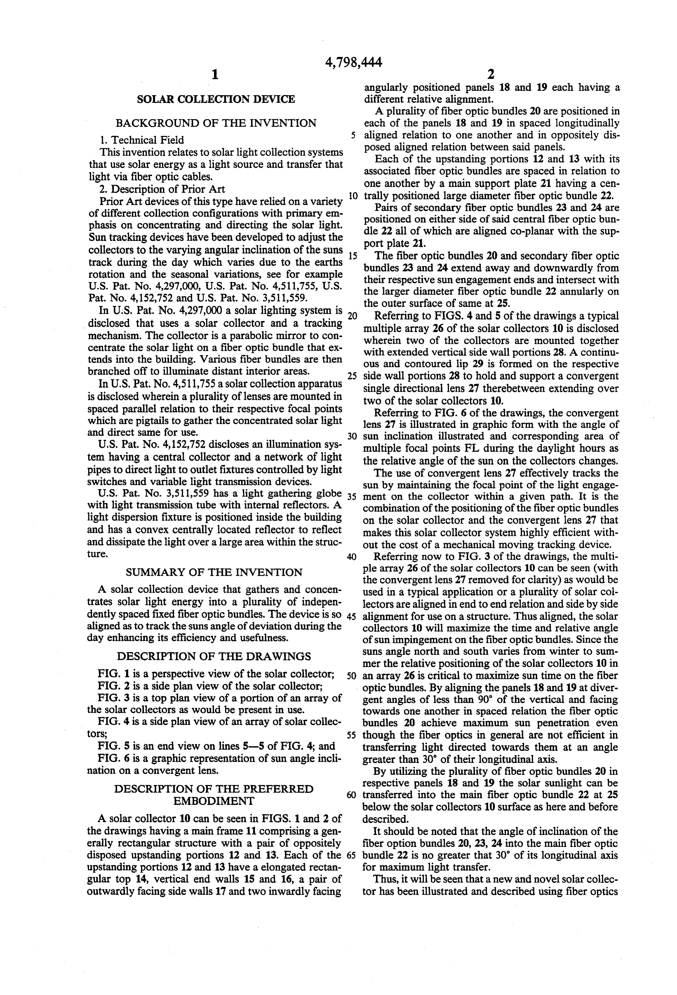
in a fixed ray to maximize the inherent variations of the interconnecting said fiber optic bundles annularly suns inclination as it travels the sky and that various below the horizontal plane of said support frame. changes and modifications may be made therein with 3. The solar collector of claim 1 wherein said each of out departing from the spirit of the invention, therefore said upstanding portions are identical and are intercon I claim: 5 nected by a flat planar portion of said main frame sup 1. A solar collection device comprising a plurality of port frame having said main fiber optic bundle and fiber optic bundles of a pre-determined size, a main support frame having oppositely disposed angularly secondary fiber optic bundles positioned therein. aligned upstanding portions in spaced relative relation a plurality ofcollector 4. A solar device comprising in combination fiber optic bundles spaced within a main to one another, pairs of angularly arranged panels are O support frame having oppositely disposed angularly positioned on each of said upstanding portions of said aligned upstanding portions in spaced relative relation main support frame, a main fiber optic bundle and sec ondary fiber optic bundles are positioned between said to one another, a main fiber optic bundle and secondary upstanding portions on said main support frame on the fiber optic bundles are positioned between said upstand same horizontal plane, some of said fiber optic bundles 15 ing portions on said main support frame, some of said are arranged in aligned spaced relation in said angularly fiber optic bundles are arranged in aligned spaced rela arranged panels on said upstanding portions, a conver tion in angularly arranged panels on said upstanding gent lens in spaced relation to said plurality of fiber portions of said main support frame, a convergent less optic bundles, means for interconnecting said plurality positioned in spaced relation to all of said plurality of of fiber optic bundles with said main fiber optic bundle. 20 fiber optic bundles on said support frame, said upstand 2. The solar collection device of claim 1 wherein said ing portions of said main support frame are angularly means for interconnecting said plurality of fiber optic arranged in oppositely disposed relation to one another. bundles with said main fiber optic bundle comprises it k . . .
Provenance
- Collection
- Cited prior art
- Original PDF
- patentimages.storage.googleapis.com →
- Filed
- 1987-06-12
- Pages
- 5
- Method
- pdftotext (the PDF's own text layer) + pdftoppm 300dpi page scans
- Source
- Google Patents bibliographic record
- Granted
- 1989-01-17
- Inventors
- Bret L. McLean
- Transcribed from
- patentimages.storage.googleapis.com →