patent · US4425905
Sunlight collecting and concentrating apparatus
17 January 1984
Page 1 — bibliographic record
5 : ;; ;; ; i. : '.
United States Patent (19) 11) 4,425,905 Mori 45) Jan. 17, 1984 54 SUNLIGHT COLLECTING AND Primary Examiner-Samuel Scott CONCENTRATINGAPPARATUS Assistant Examiner-Margaret A. Focarino 76 Inventor: Kei Mori, 3-16-3-501, Kaminoge, Attorney, Agent, or Firm-Merchant, Gould, Smith, Setagaya-ku, Tokyo, Japan Edell, Welter & Schmidt
A sunlight collecting and concentrating apparatus hav 22 Filed: Jul. 15, 1982 ing a mirror or lens device rotated independently about (30) Foreign Application Priority Data a vertical and horizontal axis, respectively, so that the Jul. 18, 1981 JP Japan ................................ 56-1250 mirror or lens always faces the sun when despite change is in the sun's azimuth and altitude. An optical conduc 51 Int. Cl. ................................................. F24J 3/02 tor is provided which has a first section arranged coaxi 52 U.S. C. .................................... 126/425; 126/439; ally with the horizontal axis and a second section ar 350/96.10; 350/96.24 ranged coaxially with the vertical axis. Means are pro 58) Field of Search ............... 126/424, 425, 438, 439, vided between the first and second conductors for al 126/451; 350/96.10, 96.24, 289,293,294, 96.15; lowing relative rotation therebetween. Thus, no wind 353/3 ing torsion of the conductors take place during the rotational movement of the mirror about the first and 56 References Cited the second axes. Means are also provided for preventing
4,026,267 5/1977 Coleman ...................... 350/96.24 X from the tracking sensor device to a control circuit for 4,201,197 5/1980 Dismer ................................ 126/451 operating the mirror.
4,297,000 10/1981 Fries ............................. 350/96.24 X 4,307,936 12/1981 Ochiai .............................. 350/96.24 16 Claims, 6 Drawing Figures
ONTROL
CIRCUIT
Page 2
Drawing sheet — no readable text.
Page 3
Drawing sheet — no readable text.
Page 4
Drawing sheet — no readable text.
Page 5
Drawing sheet — no readable text.
Page 6
FIG. 4 shows a diagram of a radio transmission sys
SUNLIGHT COLLECTING AND tem for transmitting the signal from the tracking sensor CONCENTRATING APPARATUS to the controller.
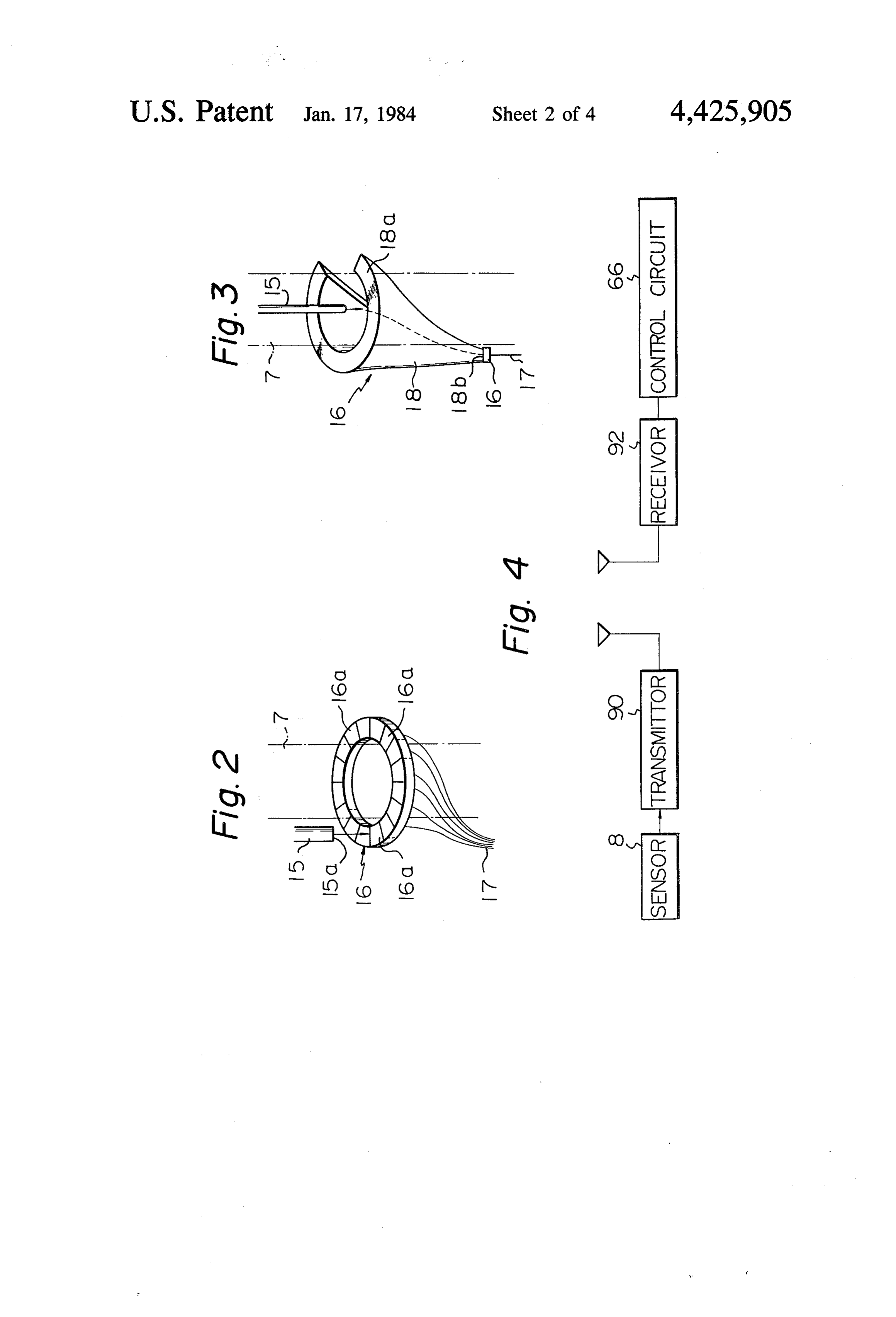
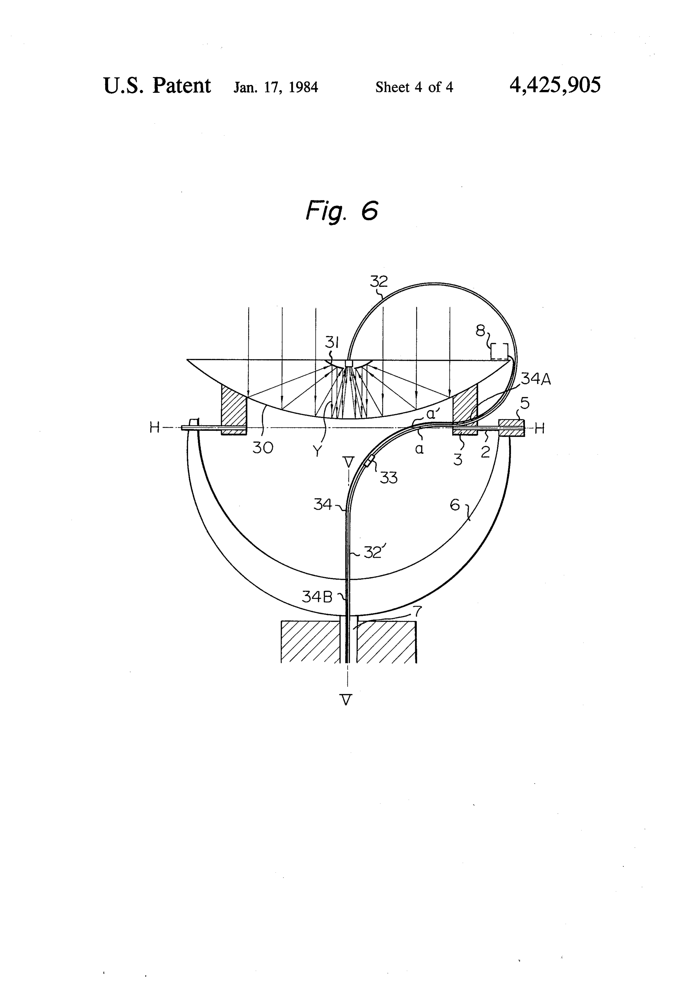
FIGS. 5 and 6 show other embodiment of the present
BACKGROUND OF THE INVENTION 5 invention.
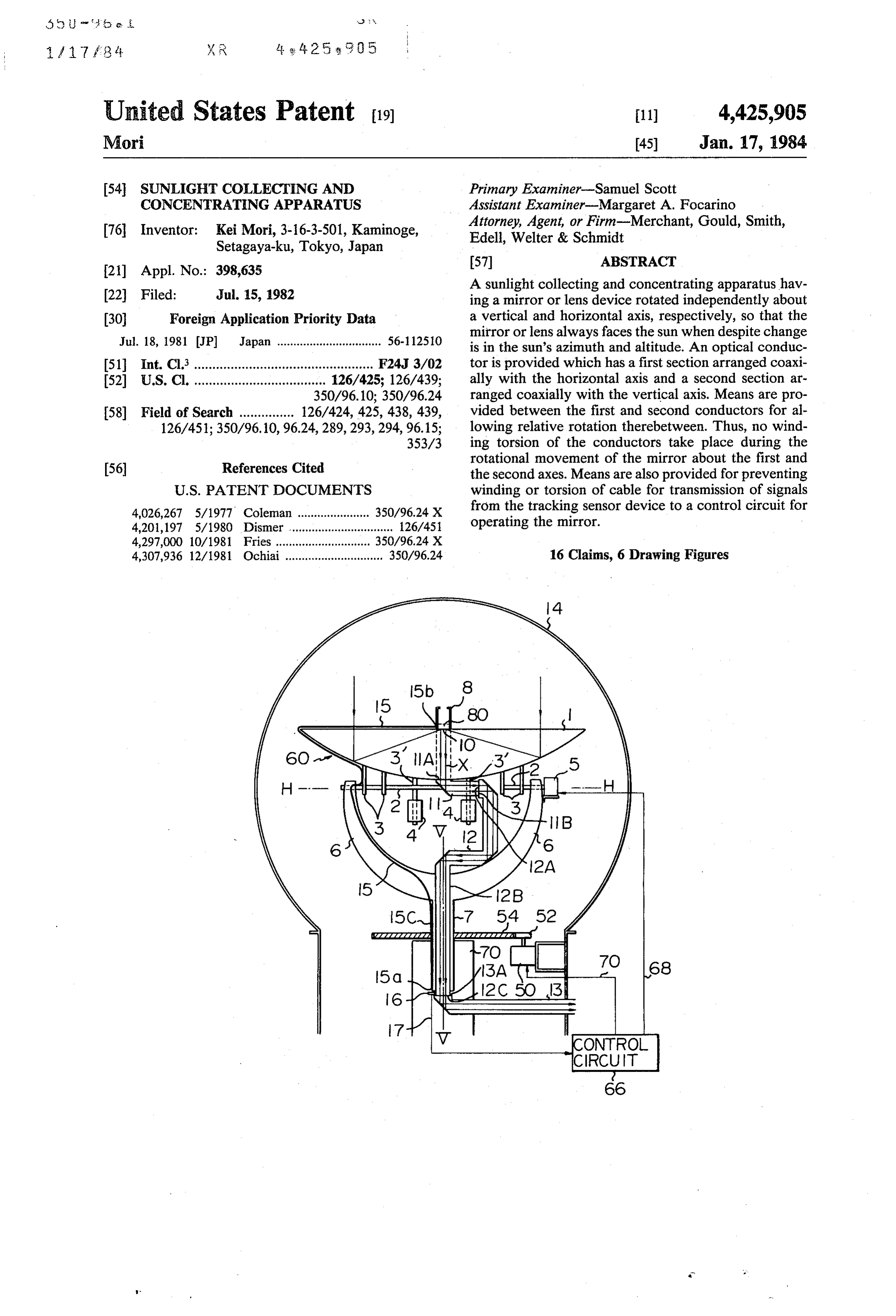
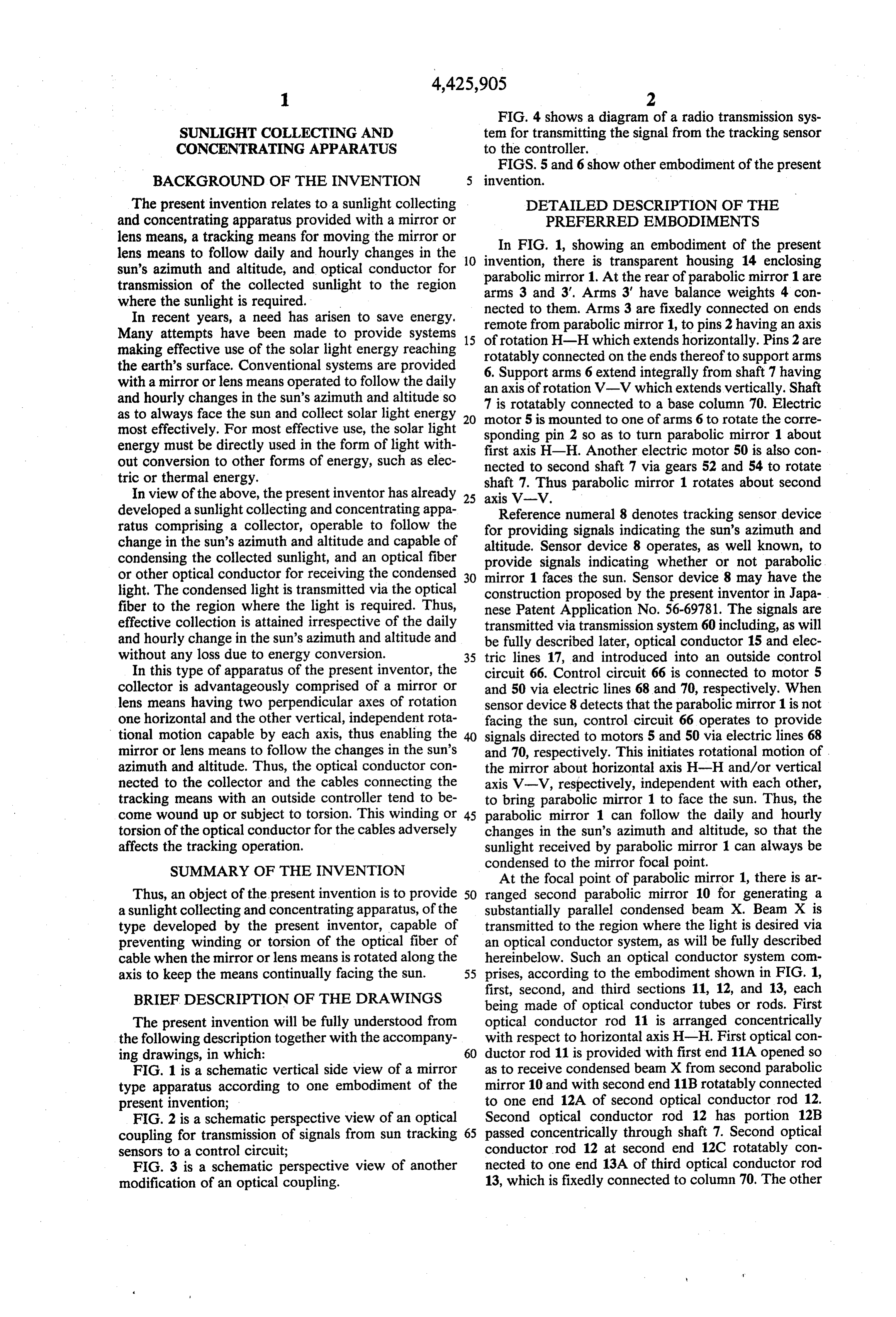
The present invention relates to a sunlight collecting DETAILED DESCRIPTION OF THE and concentrating apparatus provided with a mirror or PREFERRED EMBODIMENTS lens means, a tracking means for moving the mirror or In FIG. 1, showing an embodiment of the present lens means to follow daily and hourly changes in the 10 invention, there is transparent housing 14 enclosing sun's azimuth and altitude, and optical conductor for parabolic mirror 1. At the rear of parabolic mirror 1 are transmission of the collected sunlight to the region arms 3 and 3'. Arms 3' have balance weights 4 con where the sunlight is required.
In recent years, a need has arisen to save energy. remote from parabolic 3mirror nected to them. Arms are fixedly connected on ends 1, to pins 2 having an axis
Many attempts have been made to provide systems 15 of rotation H-H which extends horizontally. Pins 2 are making effective use of the solar light energy reaching rotatably connected on the ends thereof the earth's surface. Conventional systems are provided 6. Support arms 6 extend integrally fromtoshaft support arms 7 having with a mirror or lens means operated to follow the daily an axis of rotation V-V which extends vertically. Shaft and hourly changes in the sun's azimuth and altitude so 7 is rotatably connected to a base column 70. Electric as to always face the sun and collect solar light energy 20 motor 5 is mounted to one of arms 6 to rotate the corre most effectively. For most effective use, the solar light sponding pin 2 so as to turn parabolic mirror 1 about energy must be directly used in the form of light with first axis H-H. Another electric motor 50 is also con out conversion to other forms of energy, such as elec nected to second shaft 7 via gears 52 and 54 to rotate tric or thermal energy.
In view of the above, the present inventor has already 25 shaft 7. Thus parabolic mirror 1 rotates about second axis V-V.
developed a sunlight collecting and concentrating appa ratus comprising a collector, operable to follow the forReference numeral 8 denotes tracking sensor device providing signals indicating the sun's azimuth and change in the sun's azimuth and altitude and capable of condensing the collected sunlight, and an optical fiber altitude. Sensor device 8 operates, as well known, to provide signals indicating whether or not parabolic or other optical conductor for receiving the condensed 30 mirror 1 faces the sun. Sensor device 8 may have the light. The condensed light is transmitted via the optical construction proposed by the present inventor in Japa fiber to the region where the light is required. Thus, nese Patent Application No. 56-69781. The signals are effective collection is attained irrespective of the daily transmitted via transmission system 60 including, as will and hourly change in the sun's azimuth and altitude and be fully described later, optical conductor 15 and elec without any loss due to energy conversion. 35 tric lines 17, and introduced into an outside control In this type of apparatus of the present inventor, the circuit 66. Control circuit 66 is connected to motor 5 collector is advantageously comprised of a mirror or and 50 via electric lines 68 and 70, respectively. When lens means having two perpendicular axes of rotation sensor device 8 detects that the parabolic mirror 1 is not one horizontal and the other vertical, independent rota facing the sun, control circuit 66 operates to provide tional motion capable by each axis, thus enabling the 40 signals directed to motors 5 and 50 via electric lines 68 mirror or lens means to follow the changes in the sun's and 70, respectively. This initiates rotational motion of . azimuth and altitude. Thus, the optical conductor con the mirror about horizontal axis H-H and/or vertical nected to the collector and the cables connecting the axis V-V, respectively, independent with each other, tracking means with an outside controller tend to be to bring parabolic mirror 1 to face the sun. Thus, the come wound up or subject to torsion. This winding or 45 parabolic mirror 1 can follow the daily and hourly torsion of the optical conductor for the cables adversely changes in the sun's azimuth and altitude, so that the affects the tracking operation. sunlight received by parabolic mirror 1 can always be SUMMARY OF THE INVENTION condensed to the mirror focal point.
At the focal point of parabolic mirror 1, there is ar
Thus, an object of the present invention is to provide 50 ranged second parabolic mirror 10 for generating a a sunlight collecting and concentrating apparatus, of the substantially parallel condensed beam X. Beam X is type developed by the present inventor, capable of transmitted to the region where the light is desired via preventing winding or torsion of the optical fiber of an optical conductor system, as will be fully described cable when the mirror or lens means is rotated along the hereinbelow. Such an optical conductor system com axis to keep the means continually facing the sun. 55 prises, according to the embodiment shown in FIG. 1, first, second, and third sections 11, 12, and 13, each
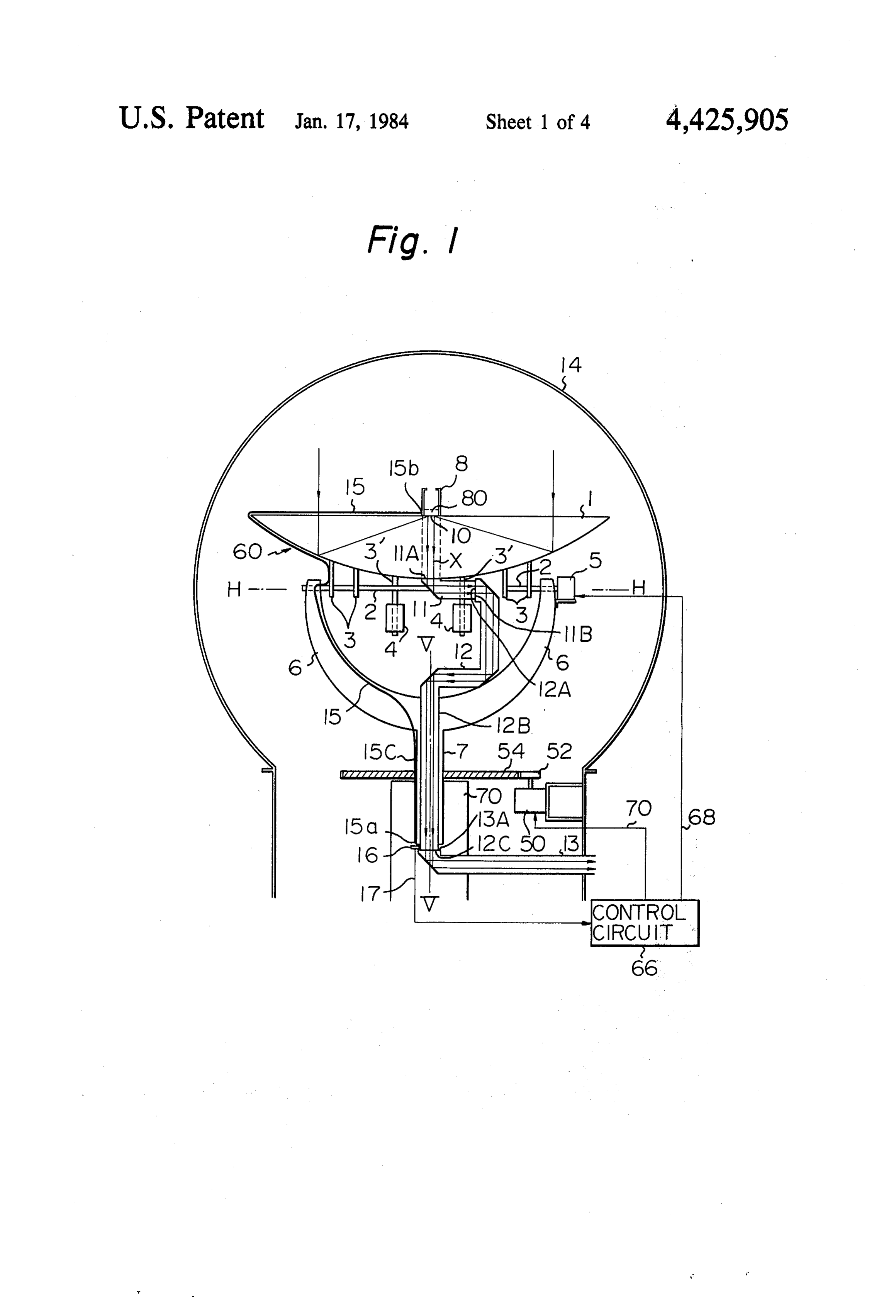
BRIEF DESCRIPTION OF THE DRAWINGS being made of optical conductor tubes or rods. First The present invention will be fully understood from optical conductor rod 11 is arranged concentrically the following description together with the accompany with respect to horizontal axis H-H. First optical con ing drawings, in which: 60 ductor rod 11 is provided with first end 11A opened so FIG. 1 is a schematic vertical side view of a mirror as to receive condensed beam X from second parabolic type apparatus according to one embodiment of the mirror 10 and with second end 11B rotatably connected present invention; to one end 12A of second optical conductor rod 12. FIG. 2 is a schematic perspective view of an optical Second optical conductor rod 12 has portion 12B coupling for transmission of signals from sun tracking 65 passed concentrically through shaft 7. Second optical sensors to a control circuit; conductor rod 12 at second end 12C rotatably con FIG. 3 is a schematic perspective view of another nected to one end 13A of third optical conductor rod modification of an optical coupling. 13, which is fixedly connected to column 70. The other
Page 7
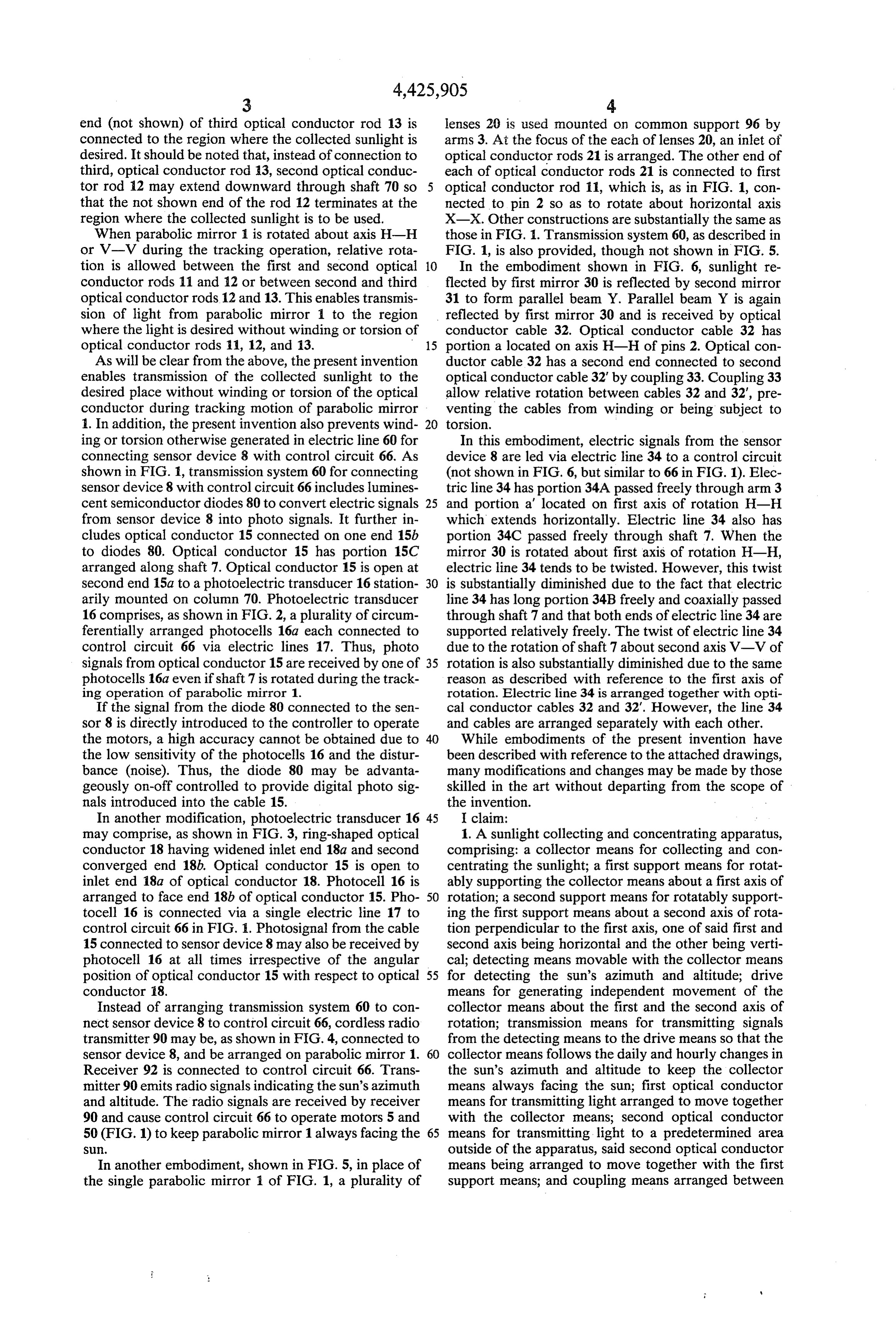
end (not shown) of third optical conductor rod 13 is lenses 20 is used mounted on common support 96 by connected to the region where the collected sunlight is arms 3. At the focus of the each of lenses 20, an inlet of desired. It should be noted that, instead of connection to optical conductor rods 21 is arranged. The other end of third, optical conductor rod 3, second optical conduc each of optical conductor rods 21 is connected to first tor rod 2 may extend downward through shaft 70 so optical conductor rod 11, which is, as in FIG. 1, con that the not shown end of the rod 12 terminates at the nected to pin 2 so as to rotate about horizontal axis region where the collected sunlight is to be used. X-X. Other constructions are substantially the same as When parabolic mirror is rotated about axis H-H those in FIG. 1. Transmission system 60, as described in or V-V during the tracking operation, relative rota FIG. 1, is also provided, though not shown in FIG. 5. tion is allowed between the first and second optical 10 In the embodiment shown in FIG. 6, sunlight re conductor rods 11 and 12 or between second and third flected by first mirror 30 is reflected by second mirror optical conductor rods 12 and 13. This enables transmis 31 to form parallel beam Y. Parallel beam Y is again sion of light from parabolic mirror 1 to the region reflected by first mirror 30 and is received by optical where the light is desired without winding or torsion of conductor cable 32. Optical conductor cable 32 has optical conductor rods 11, 12, and 13. 15 portion a located on axis H-H of pins 2. Optical con As will be clear from the above, the present invention ductor cable 32 has a second end connected to second enables transmission of the collected sunlight to the optical conductor cable 32' by coupling 33. Coupling 33 desired place without winding or torsion of the optical allow relative rotation between cables 32 and 32", pre conductor during tracking motion of parabolic mirror venting the cables from winding or being subject to 1. In addition, the present invention also prevents wind torsion.
ing or torsion otherwise generated in electric line 60 for In this embodiment, electric signals from the sensor connecting sensor device 8 with control circuit 66. As device 8 are led via electric line 34 to a control circuit shown in FIG. , transmission system 60 for connecting (not shown in FIG. 6, but similar to 66 in FIG. 1). Elec sensor device 8 with control circuit 66 includes lumines tric line 34 has portion 34A passed freely through arm 3 cent semiconductor diodes 80 to convert electric signals 25 and portion a located on first axis of rotation H-H from sensor device 8 into photo signals. It further in which extends horizontally. Electric line 34 also has cludes optical conductor 15 connected on one end 15b portion 34C passed freely through shaft 7. When the to diodes 80. Optical conductor 15 has portion 15C mirror 30 is rotated about first axis of rotation H-H, arranged along shaft 7. Optical conductor 15 is open at electric line 34 tends to be twisted. However, this twist second end 15a to a photoelectric transducer 16 station 30 is substantially diminished due to the fact that electric arily mounted on column 70. Photoelectric transducer line 34 has long portion 34B freely and coaxially passed 16 comprises, as shown in FIG. 2, a plurality of circum through shaft 7 and that both ends of electric line 34 are ferentially arranged photocells 16a each connected to supported relatively freely. The twist of electric line 34 control circuit 66 via electric lines 17. Thus, photo due to the rotation of shaft 7 about second axis V-V of signals from optical conductor 15 are received by one of 35 rotation is also substantially diminished due to the same photocells 16a even if shaft 7 is rotated during the track reason as described with reference to the first axis of ing operation of parabolic mirror 1. rotation. Electric line 34 is arranged together with opti If the signal from the diode 80 connected to the sen cal conductor cables 32 and 32. However, the line 34 sor 8 is directly introduced to the controller to operate and cables are arranged separately with each other.
the motors, a high accuracy cannot be obtained due to 40 While embodiments of the present invention have the low sensitivity of the photocells 16 and the distur been described with reference to the attached drawings, bance (noise). Thus, the diode 80 may be advanta many modifications and changes may be made by those geously on-off controlled to provide digital photo sig skilled in the art without departing from the scope of nals introduced into the cable 15. the invention.
In another modification, photoelectric transducer 16 45 I claim:
may comprise, as shown in FIG. 3, ring-shaped optical 1. A sunlight collecting and concentrating apparatus, conductor 18 having widened inlet end 18a and second comprising: a collector means for collecting and con converged end 18b. Optical conductor 15 is open to centrating the sunlight; a first support means for rotat inlet end 18a of optical conductor 18. Photocell 16 is ably supporting the collector means about a first axis of arranged to face end 18b of optical conductor 15. Pho 50 rotation; a second support means for rotatably support tocell 16 is connected via a single electric line 17 to ing the first support means about a second axis of rota control circuit 66 in FIG. I. Photosignal from the cable tion perpendicular to the first axis, one of said first and 15 connected to sensor device 8 may also be received by second axis being horizontal and the other being verti photocell 16 at all times irrespective of the angular cal; detecting means movable with the collector means position of optical conductor 15 with respect to optical 55 for detecting the sun's azimuth and altitude; drive conductor 18. means for generating independent movement of the Instead of arranging transmission system 60 to con collector means about the first and the second axis of nect sensor device 8 to control circuit 66, cordless radio rotation; transmission means for transmitting signals transmitter 90 may be, as shown in FIG.4, connected to from the detecting means to the drive means so that the sensor device 8, and be arranged on parabolic mirror 1. 60 collector means follows the daily and hourly changes in Receiver 92 is connected to control circuit 66. Trans the sun's azimuth and altitude to keep the collector mitter 90 emits radio signals indicating the sun's azimuth means always facing the sun; first optical conductor and altitude. The radio signals are received by receiver means for transmitting light arranged to move together 90 and cause control circuit 66 to operate motors 5 and with the collector means; second optical conductor 50 (FIG. 1) to keep parabolic mirror 1 always facing the 65 means for transmitting light to a predetermined area St. outside of the apparatus, said second optical conductor In another embodiment, shown in FIG. 5, in place of means being arranged to move together with the first the single parabolic mirror 1 of FIG. 1, a plurality of support means; and coupling means arranged between
Page 8
the first and second optical conductor means for trans 10. An apparatus according to claim 1, wherein said mitting the light from the former to the latter while transmission means comprises a radio means connected permitting relative rotation therebetween. to the sensor for providing signals indicating the sun's 2. An apparatus according to claim 1, wherein said azimuth and altitude and a radio receive means con collector means comprises a single parabolic mirror for nected to the drive means for driving the collector in generating a concentrated beam directed to the first accordance with the sun's position, said receiver being optical conductor means. arranged on a desired position remote from the collec 3. An apparatus according to claim 2, further com tor.
prising a second parabolic mirror arranged for catching 10 11. An apparatus according to claim 1, wherein said transmission means comprises a first transducer con the beam received by the first mirror and for directing nected to the sensor for converting the electric signals the beam to the first optical conductor means. from the sensor to photo signals, an optical signal cable 4. An apparatus according to claim 1, wherein said connected to the first transducer, a second transducer collector means comprises a plurality of lenses and a means for converting the optical signals from the opti plurality of supplemental optical conductors each ar 15 cal signal cable to electric signals, and an electric line ranged to receive light from each lens on one end and connecting the second transducer means to the drive each connected to the first optical conductor means on eaS.
the other end.
5. An apparatus according to claim 1, wherein said first12.transducer
An apparatus according to claim 11, wherein said means comprises luminescent semicon coupling means is located coaxially with respect to the 20 ductor diodes and a modulator for converting signals first axis of rotation. from the diodes to digital signals by pulsatively modu 6. An apparatus according to claim 1, wherein said lating the signals from the transducer. first optical conductor means comprises an optical con 13. An apparatus according to claim 11, wherein said ductor member arranged coaxially with respect to the second transducer means comprises a plurality of cir first axis, said optical conductor member having an inlet 25 cumferentially located photocells fixedly connected to end opened outwardly for receiving the collected light the second support means and arranged to open to the from the collector means and a second end rotatably end of the optical signal cable remote from the sensor, connected to the coupling means. each of photocells being connected to the drive means. 7. An apparatus according to claim 1, wherein said 14. An apparatus according to claim 11, wherein said second conductor means comprises an optical conduc 30 second transducer means comprises an optical conduc tor member having an end rotatably connected to the tor of substantially tubular shape fixedly connected to coupling means, a middle portion arranged concentri the second support means, having an inlet with a sub cally with the second axis, and a second end connectible stantially circular surface opened to the end of the opti to the area where the collected sunlight is used. cal signal cable remote from the sensor and a converged 8. An apparatus according to claim 7, further com 35 and a photosensor facing the converged end for receiv prising another optical conductor member fixed to the ing photo signal, and an electric line connecting the second support means, a second coupling means for photo sensor with the drive means.
rotatable connection of the second conductor means 15. An apparatus according to claim 1, wherein said with the other optical conductor member, said other transmission means comprises an electric line connect optical conductor means being connected to the outside 40 ing the sensor with the drive means, said electric line of the apparatus. having a portion arranged along the first axis and a 9. An apparatus according to claim 1, said first optical second portion passed freely through the second sup conductor means comprising a flexible optical cable port concentrically along said second axis. having an inlet end located to receive the light from the 16. An apparatus according to claim 1, said drive collector, said flexible optical cable having a middle 45 means comprising a first electric motor means for gen portion located on a first axis of rotation, said second erating the rotation about the first axis, a second electric optical conductor means comprising a flexible optical motor means for generating the rotation about the sec cable substantially coaxial with respect to the second ond axis, and a control circuit connecting the transmis axis of rotation, said coupling means being located at a sion means with the first and second electric motor position spaced from the first and second axis of rota 50 eas. sk k is sk sk tion.
Provenance
- Collection
- Cited prior art
- Original PDF
- patentimages.storage.googleapis.com →
- Filed
- 1982-07-15
- Pages
- 8
- Method
- pdftotext (the PDF's own text layer) + pdftoppm 300dpi page scans
- Source
- Google Patents bibliographic record
- Granted
- 1984-01-17
- Inventors
- Kei Mori
- Transcribed from
- patentimages.storage.googleapis.com →