patent · US4492424A
Solar collector
8 January 1985
Page 1 — bibliographic record
S. U - 6 1. SR 1 / 8 A 85 OR 4 p. 492 4.24
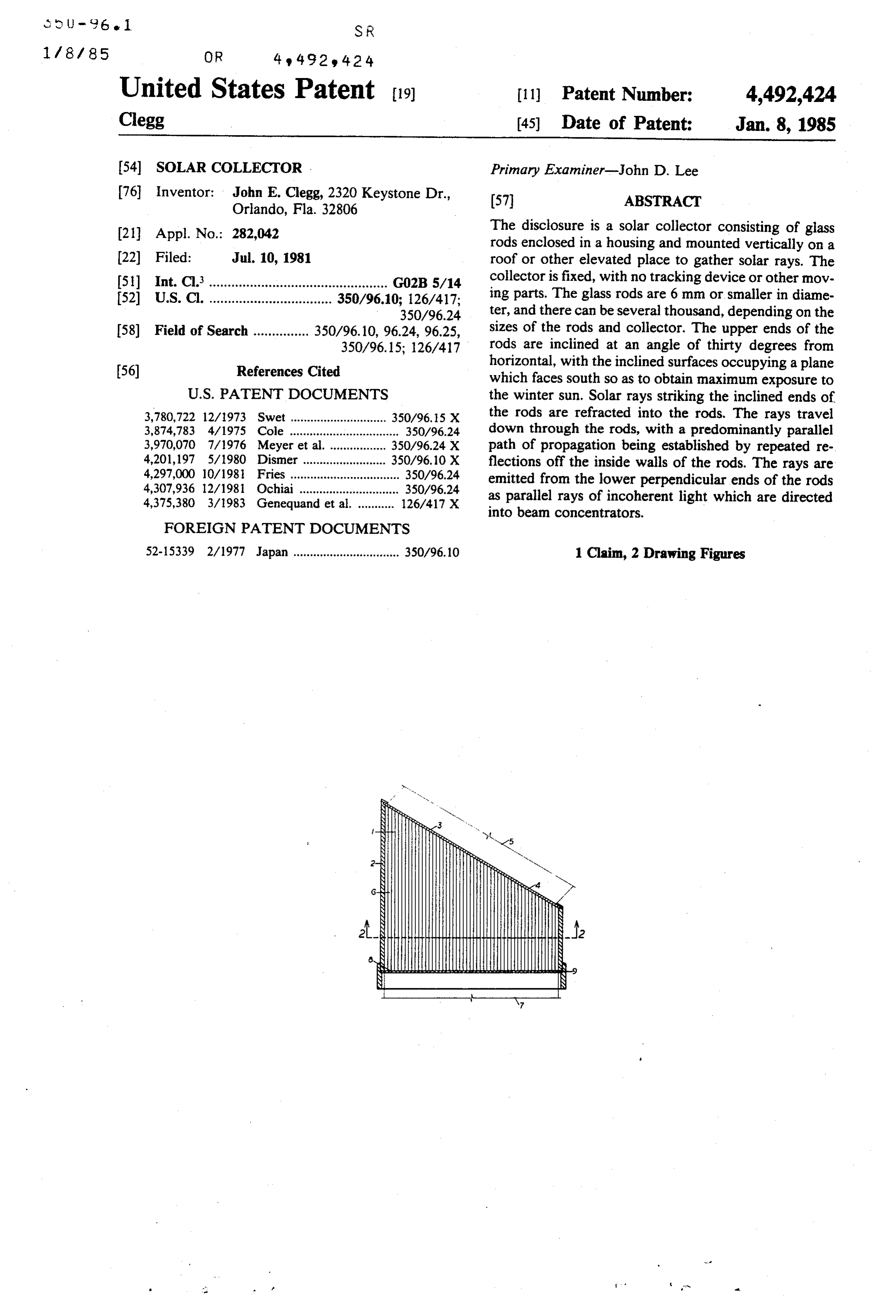
United States Patent (19) (11) Patent Number: 4,492,424 Clegg (45) Date of Patent: Jan. 8, 1985 (54) SOLAR COLLECTOR . Primary Examiner-John D. Lee 76 Inventor: John E. Clegg, 2320 Keystone Dr., (57) ABSTRACT
Orlando, Fla. 32806 21 Appl. No.: 282,042 The disclosure is a solar collector consisting of glass rods enclosed in a housing and mounted vertically on a 22 Filed: Jul. 10, 1981 roof or other elevated place to gather solar rays. The 51) Int. Cl................................................. GO2B 5/14 collector is fixed, with no tracking device or other mov 52 U.S. C. ................................. 350/96.10; 126/417; ing parts. The glass rods are 6 mm or smaller in diame 350/96.24 ter, and there can be several thousand, depending on the 58) Field of Search ............... 350/96.10, 96.24, 96.25, sizes of the rods and collector. The upper ends of the 350/96.15; 126/417 rods are inclined at an angle of thirty degrees from (56) References Cited horizontal, with the inclined surfaces occupying a plane which faces south so as to obtain maximum exposure to
3,780,722 12/1973 Swet ............................. 350/96.15 X the rods are refracted into the rods. The rays travel 3,874,783 4/1975 Cole ................................. 350/96.24 down through the rods, with a predominantly parallel 3,970,070 7/1976 Meyer et al. ................. 350/96.24 X path of propagation being established by repeated re 4,201,197 5/1980 Dismer ......................... 350/96.10 X flections off the inside walls of the rods. The rays are 4,297,000 10/1981 Fries ................................. 350/96.24 emitted from the lower perpendicular ends of the rods 4,307,936 12/1981 Ochiai .............................. 350/96.24 as parallel rays of incoherent light which are directed 4,375,380 3/1983 Genequand et al. ........... 126/417 X into beam concentrators.
FOREIGN PATENT DOCUMENTS
52-15339 2/1977 Japan ................................ 350/96.10 1 Claim, 2 Drawing Figures
Page 2
Drawing sheet — no readable text.
Page 3
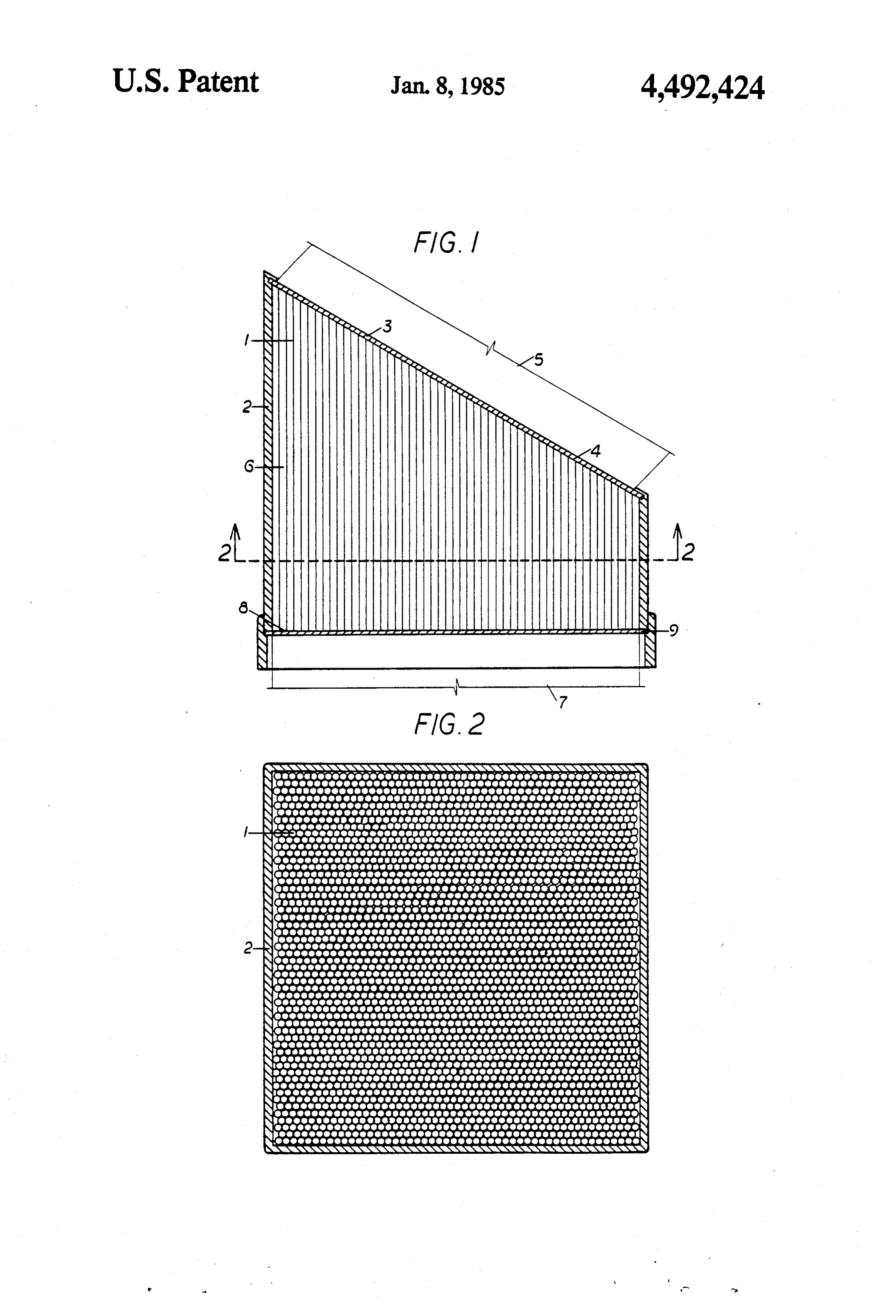
Refracted solar rays 6 are transmitted down through
SOLAR COLLECTOR glass rods 1, with a predominantly parallel path of prop agation of rays 6 being established by repeated reflec
BACKGROUND OF THE INVENTION tion off the walls of glass rods 1.
The invention relates to optical light-gathering in 5 larParallel solar rays 7 are emitted through perpendicu r lower ends 8 of glass rods 1, pass through plate glass struments, specifically to fixed glass-rod solar collec cover 9 and enter tOS.
a prismatic beam concentrator (not
Prior art includes the fixed solar panels for heating shown).
FIG. 2 is a cross sectional view of glass rods 1 and water and the dish-shaped solar receptors for convert 10 casing 2. There are 2500 rods with a diameter of 6 mm ing solar heat to electricity, with automatic tracking occupying an area of 900 cm2. This area is somewhat devices. Both of these devices are receptors only, and larger than that which would be required if a solid beam there is no means of transmitting the rays, as there is were transmitted through the collector, because there with the disclosure, which is a receptor and transmitter. must be an increase in the number of rods and in the size SUMMARY OF THE INVENTION 5 of the collector to compensate for the loss of transmit ted rays in the spaces between the rods.
The obvious advantage of the disclosure over solar The distinctive features by which the invention is receptors with tracking devices is that there are no distinguishable over prior art of record including flexi mechanical parts which must be operated by electricity ble optical fiber collectors is that rigid glass rods with and which require maintenance and replacement of 20 diameters far greater than that of optical fibers are used. parts. The disadvantage is that the collector is fixed and Whereas the diameters of optical fibers are measured in does not receive the full complement of solar rays since microns, a typical size being 5 to 10 microns, the recom its face is not perpendicular to the sun. mended diameters of the glass rods is 1 to 6 millimeters. This disadvantage is compensated for by the simple The surface area of each exposed inclined upper end expedient of increasing the size of the solar collector. 25 4 is larger than the cross sectional area of each glass rod The increase in size and weight has no effect on the 1 as shown in FIG. 2. This indicates that the collector operation of a fixed collector as it would on the tracking will be equally effective hour for hour in winter when solar receptor in which size and weight distribution are the sun is low in the sky, and when the days are short critical factors. and the need of solar energy for heating is greatest, as in 30 the summer when the sun is high in the sky.
DESCRIPTION OF THE DRAWINGS I claim:
FIG. 1 is an elevation of the solar collector. 1. A solar collector comprising vertical glass rods FIG. 2 is a cross section taken on line 2-2 of FIG. 1. enclosed in a housing under a plate glass cover, with the
DESCRIPTION OF THE PREFERRED
glass rods being of a relatively large diameter of one to 35 six millimeters, with the exposed upper ends of the glass
EMBODIMENT rods being uniformally inclined from horizontal, with FIG. 1 shows vertical glass rods 1 enclosed in hous the exposed inclined upper ends of the glass rods occu ing 2 under plate glass cover 3. Exposed inclined upper pying a common plane, with the lower ends of the glass ends 4 of glass rods 1 lie in a common plane inclined 30 rods being perpendicular to the vertical axes of the glass from horizontal, with the inclination facing the equator 40 rods and occupying a horizontal plane, with the glass so as to present maximum exposure to the winter sun. rods being supported at their lower ends by a horizontal Incipient solar beam 5 is refracted through glass cover plate glass base; as a means of receiving, refracting and 3, strikes exposed upper ends 4 and is refracted down transmitting parallel ksolar sk rays
in a vertical direction, into glass rods 1.
Provenance
- Collection
- Patents citing this work
- Pages
- 3
- Method
- pdftotext (the PDF's own text layer) + pdftoppm 300dpi page scans
- Patent office record
- patents.google.com →
- Source
- Google Patents citing-documents table
- Assignee
- Clegg John E
- Inventors
- John E. Clegg
- Published
- 1985-01-08
- Transcribed from
- patentimages.storage.googleapis.com →