patent · US1492674
Apparatus for burning hydrocarbon oils
6 May 1924
Page 1
Drawing sheet — no readable text.
Page 2
Patented May 6, 1924. 1492,674 UNITED STATES PATENT office.
CHARLES E. CHAPMAN, OF FORT EDWARD, NEw YoRK, AssIGNOR of on E-HALE To
JOSEPH GOODFELLOW, OF FORT EDWARD, NEW YORK.
APPARATUS FOR BURNING HYDRocARBON outs.
Application filed July 8, 1922, serial No. 573,644.
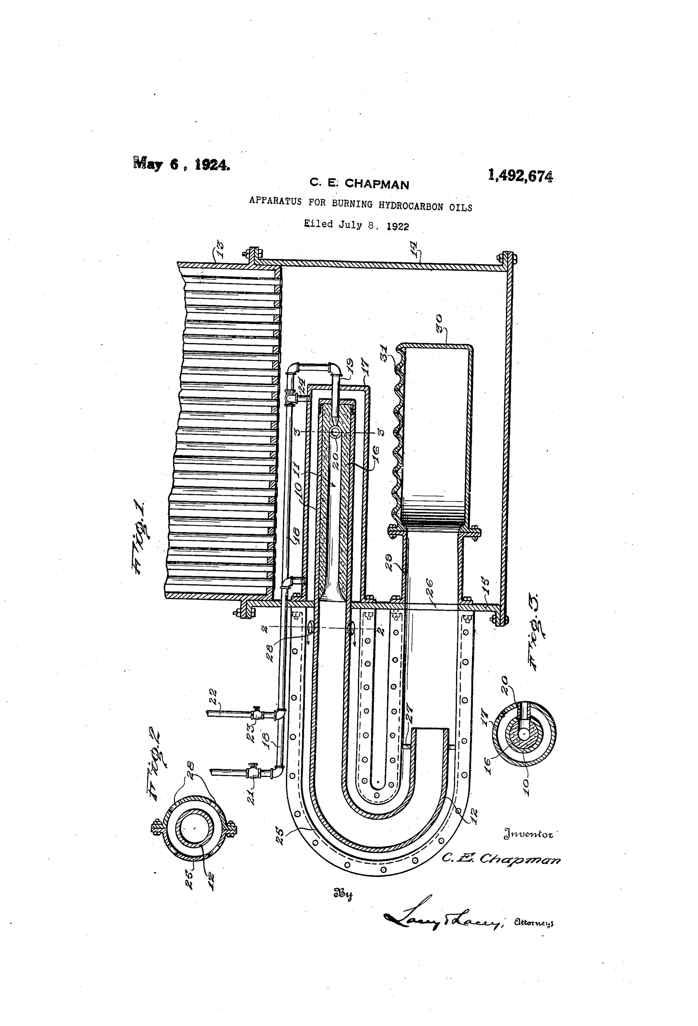
To all whom it may concern: tional view showing my improved appara 55 Be it known that II, CHARLES E. CHIAP tus in conjunction with a steam boiler. MAN, citizen of the United States, residing Figure 2 is a detail sectional view on the at Fort Edward, in the county of Washing line.Figure 2-2 of Figure 1, and 3 is a detail sectional view on the ton and State of New York, have invented certain new and useful Improvements in In carryingFigure
Apparatus, for Burning Hydrocarbon Oils, the invention into effect, Iem 60 of which the following is a specification. ploy a retort tube 10 closed at one end by a This invention relates to an improved removable cap or the like, to provide a re O apparatus for burning hydrocarbon oils, tort chamber 11 while the opposite end of being similar to the apparatus disclosed the the tube is bent to form a discharge horn 12, 65 in Patent No. 1,386,091, issued to me Au out tube being of uniform diameter through gust 2, 1921, as well as to the apparatus shownits thelength. In the drawings, I have apparatus in connection with a disclosed in Patent No. 1,419,223, issued to 15 me June 13, 1922. conventional boiler 18 having a base 14, one The invention seeks, as one of its princi Wall15,ofand, which is, for convenience, indicated 70 pal objects, to provide an apparatus where at as will be observed, the inner end of the retort tube 10 is inserted through said in the flame may be forced, cut down, or Wall otherwise regulated without disturbing the bottomto sheetextend within the base beneath the of the boiler. Mounted with 20 proper functioning of the apparatus. in the retort chamber 11 is a refractory A further object of the invention is to shell 16 closed at its inner end and 75 provide an apparatus wherein, like the pre lining vious apparatus of my former patents, heat bolted
or otherwise secured at one end to the i? a Steam jacket 17. surrounding ed products of combustion will be drawn 25 into a steam jacketed retort for breaking said chamber. Leading from a suitable oil down the chemical structure of a vaporous supply to the inner end of the tube 10 is an supply pipe 18 at the inner end of which 80 mixture of steam and oil injected into the isoilmounted an injector nozzle 19 extending retort chamber but wherein a burner will be provided for directing the flame, pro into the retort chamber 11 through the in 30 duced by subsequent combustion of said ner end of the shell 16 axially of the cham vapor, around the retort so that regardless ber and leading into the chamber at one side thereof through the wall of the jacket 17 is, of whether the flame is forced or cut down, asbest shown the flame will play over the retort across for the heated inproductsFigure 3, an inlet pipe 20 of combustion, this the opening leading into the retort chamber. pipe being disposed horizontally and enter 35 so that the heated products of combustion may always be present at said opening to ing the chamber immediately at the inner 90 be drawn into said chamber, thus insuring anglesof thereto.
end the nozzle 19 at substantially right
Interposed in the pipe 18 is the proper operation of the apparatus. an appropriate shut-off valve 21. Leading And the invention has as a still further 40 object to provide an apparatus wherein the into the steam jacket 17 at the end thereof discharge horn employed in connection with adjacent the wall 15 is a steam supply pipe the retort will be provided with a jacket shut-off valve is23,interposed
through which a supply of heated air will posite end of said chamber intofrom and leading the the op oil sup be delivered at the mouth of said horn to 45 become mingled with the vaporous mixture ply pipe 18 is an outlet pipe 24 for said of steam and oil for assisting the combus chamber. - at its ends to 100 tion thereof and wherein the flow of air the wall 15 of the basesecured
Bolted or otherwise 14 of the boiler, at through the jacket around the horn will the outer side of said wall, is a U-shaped
50 Other and incidental objects will appear jacket 25 surrounding the discharge horn 12 of the refort tube. companion
This jacket sections is split 05 hereinafter.
In the drawings: . . . . . . . longitudinally into • -` ? ? . . .. . ? ?
Figure 1 is a fragmentary longitudinal sec which, as seen in Figure 2, are provided
Page 3
with mating flanges bolted or otherwise Attention is now directed to the fact that secured together so that the sections may be readily assembled about the horn, and the burner 30 will direct the flame upwardly around the retort so that regardless of formed through the wall 15 at the lower whether end of said jacket is an opening 26. As supply of fuel the flame is forced by an augmented will be observed, the discharge horn termi tion of the fuelorsupply, is cut down by a restric 70 the flame will, at nates short of the lower end of the jacket, all times, play over the outer end of the pipe being provided with suitable lugs 2 center 20 for not only excluding air but also provid ing the free end of the horn within the 10 jacket, and formed in the jacket near its ing, at all times, heated products of combus upper end is a series of spaced air inlet pipe. tion in the proximity of the outer end of the 75 openings 28. Bolted or otherwise secured ucts ofFailure in the supply of heated prod combustion at the pipe 20 through to the wall 15 at its inner side to surround deflection or restriction of the flame to, in the opening 26 in said wall is a tube 29 5 forming, in effect, a continuation of the turn, cause failure of the apparatus, will jacket, and detachably mounted upon Said pipe accordingly be prevented. However, the 80 tube is a bulner 30 lying beneath the retort through 20 is located horizontally to open in a plane there with. At its upper side, this verticallyoneto side open of the retort rather than through the lower side burner is provided with jet openings 31, the 20 burne being otherwise closed with respect of the retort so that the flame cannot rise to the base of the boiler. directly into said pipe to cause overheat In operation, oil under pressure is fed ingHaving of the retort chamber.
through the pipe 18 to the nozzle 19 while is claimed thus described the invention, what as new is:
steam is supplied under pressure through 1. The herein described apparatus for
the pipe 22 to the steam jacket 17 and since burning fuel oils including a steam jacketed the burner 30 is located immediately beneath retort chamber having a discharge horn, an the retort, flame from the burner will play oil supply receiving around said jacket for Superheating the of said chamber andsteam from the jacket steam therein. Accordingly, superheated means discharging in said chamber,nebulizing including a burner steam will be discharged through the outlet for directing flame toward the chamber and pipe 24 to become mingled with the oil pass fed by the horn, and means for conducting ing through the pipe 18 for atomizing the oil so that a vaporous mixture of oil and steam air2.toThe the burner.
herein described apparatus for will be discharged from the nozzle into the burning fuel
retort chamber. The discharge of the noz retort chamberoilshaving including a steam jacketed a älischarge horn, an 00 zle will, of course, create a Suction in the oil supply receiving steam from the jacket pipe 20 so that the heated ??(??????? of coln bustion will be coincidently drawn in through means discharging in said chamber,nebulizing of said chamber and including a burner 40 said pipe into the retort chamber to become for directing flame toward the chamber and mixed with the vapor therein. The temper fed by the horn, means for conducting air 105 ature of said chamber will thus be greatly to the burner, and a horizontally disposed in elevated with the result that the chemical take for the products of combustion leading structure of the oil and steam of the vapor into the chamber at one side thereof. will be broken down. From the retort cham 3. The herein described apparatus for
ber the vapor will then be impelled through burning feul the discharge horn 12 to issue from the retort chamberoilshaving including a steam jacketed O a ischarge horn, an mouth thereof into the jacket 25, thereby Set oil supply receiving steam from the jacket ting up a suction in the jacket acting to of said chamber and including
draw in a supply of air through the inlet means discharging in said chamber,nebulizing a burner openings 28 of the jacket so that before for directing flame toward the chamber and ls the fuel vapor reaches the burner air will fed by the horn, and an individual air jacket be mixed therewith for supplying oxygen surrounding the horn.
auxiliary to that derived from the steam in 4. The herein described apparatus for
jected through the nozzle 19. As will be burning fuel oils including a steam jacketed seen, the airflowing through the jacket will retort chamber having a discharge horn, an be caused to traverse the length of the dis oil supply receiving charge horn so that the air, before becom of said chamber andsteam from the jacket ing mingled with the fuel vapor, will be means discharging in the chamber,nebulizing including a jacket 60 heated to a high temperature for thus fur surrounding the horn, the jacket being pro ther augmenting the combustibility of the vided with an opening whereby air will be vapor. Practically perfect combustion will aspirated accordingly be had at the burner. Further charge fromthrough the jacket by the dis more, as will be noted, the air flowing recting flame toward theandretort the horn, a burner for di chamber fed 65 through the jacket 25 will tend to cool the by the horn.
discharge horn. 5. The herein described apparatus for
Page 4
means discharging in said chamber, and 45 burning fuel oils including a steam jacketed means retort chamber having a discharge horn, an horn with for supplying the discharge from the oil supply receiving steam from the jacket 9. The herein fresh air.
of said chamber and including nebulizing burning fuel oil including described apparatus for means discharging in said chamber, a jacket retort chamber having a discharge a steam jacketed 50 surrounding said horn having the horn dis oil supply receiving steam from thehorn, an jacket charging therein and provided with an air of said chamber and including nebulizing inlet opening whereby air will be drawn means discharging in said chamber, and as through the jacket about the horn, and a
O burner for directing flame toward the retort pirating means associated with the horn chamber in communication with said jacket. whereby the discharge from the horn will 65 6. The herein described apparatus for function to aspirate air through said means. 10. The herein described apparatus for burning fuel oils including a steam jacketed burning fuel oils including a steam jacketed retort chamber having a discharge horn, an 5 oil supply receiving steam from the jacket retort chamber having a discharge horn, an of said chamber and including nebulizing oil supply receiving steam from the jacket 60
means discharging in said chamber, a jacket of saiddischarging chamber and including nebulizing surrounding the horn, the jacket being pro means for directing flame in said chamber, a burner toward the chamber and vided near one end with an air inlet opening 20) and having the horn discharging therein fed by the horn, and means supplying the near the opposite end of the horn whereby burner with air and directing the discharge 65 air will be drawn through the jacket, and a 11. Thehorn from the toward the burner.
herein described apparatus for burner for directing flame toward the retort burning fuel oils including a steam jacketed chamber in communication with said jacket. retort chamber having a discharge 25 7. The herein described apparatus fol' supply receiving steam from thehorn, an burning fuel oils including a steam jacketed oil jacket retort chamber having a discharge horn, an of said chamber and including nebulizing means discharging into said chamber, a oil supply receiving steam from the jacket burner for directing flame toward the cham of the chamber and including nebulizing 30 means discharging in said chamber, an inlet ber and fed by the horn, and means supply for the products of combustion leading into ing the burner with air and forming a jacket the chamber adjacent the discharge end of for12.theThe horn.
said nebulizing means, a jacket surrounding burning fuelherein described apparatus for the horn, the jacket being provided with an retort chamberoilshaving including a steam jacketed a ??isöharge horn, an 35 air inlet opening and having the horn dis charging therein whereby air will be drawn oil supply receiving steam from the jacket 80 through the jacket, and a burner for direct of saiddischarging chamber and including nebulizing ing flame toward the retort chamber in com means jacket associated into said chamber, and a with the horn whereby the munication with said jacket. discharge from the horn will function to 85 40 8. The herein described apparatus for aspirate air through the jacket. burning fuel oils including a steam jacketed In testimony whereof I affix my signature. retort chamber having a discharge horn, an oil supply receiving steam from the jacket of said chamber and including nebulizing CHARLES E. CHAPMAN. L. s.
Provenance
- Collection
- Cited prior art
- Original PDF
- patentimages.storage.googleapis.com →
- Filed
- 1922-07-08
- Pages
- 4
- Method
- pdftotext (the PDF's own text layer) + pdftoppm 300dpi page scans
- Source
- Google Patents bibliographic record
- Granted
- 1924-05-06
- Inventors
- Charles E Chapman
- Transcribed from
- patentimages.storage.googleapis.com →