patent · US3931806
Method and apparatus for storing a medium heated by solar energy
13 January 1976
Page 1 — bibliographic record
United States Patent (19) 11 3,931,806 Hayes 45 Jan. 13, 1976
54 METHOD AND APPARATUS FOR STORING 57 ABSTRACT A MEDIUM HEATED BY SOLAR ENERGY A heating system has means for directing heat only to 75) Inventor: Thomas Edward Hayes, Goshen, a portion of a medium for storing heat which portion Ind. is at a temperature below that to which heating means 73 Assignee: Johnson Service Company, then heats the medium. The system then functions to store heat in the medium during periods of less-than
Milwaukee, Wis. maximum heating of the medium without degrading 22 Filed: May 6, 1974 the temperature of a higher-temperature portion of the medium. The system has particular utility with a (21) Appl. No.: 467,400 solar heat collector from which the available heat var ies with the intensity of the solar energy. Heat is then 52 U.S. Cl.................................... 126/400; 165/18 collected in the portion of the medium during periods 5 Int. Cl”............................................ F24J 3/02 of marginal solar energy intensity without degrading 58 Field of Search .............. 126/271, 400; 165/18; the higher temperature of another portion of the me 2371 A dium heated to a higher temperature during a prior period of greater solar energy intensity. In a specific 56 References Cited embodiment the system has three compartments for UNITED STATES PATENTS separating a fluid heat-storing medium into portions, a 2,342,211 2/1944 Newton............................... 2371. A pump supplying the fluid to a solar heat collector, and 2,544,474 3/1951 Swanton, Jr........................ 237/1 A a pump supplying the fluid to a heat exchanger for 2,575,478 l l 1951 Wilson................................ 23711 A heating a house. The means for directing heat to a 2,713,252 7/1955 Jackson et al...... ... 65/18 portion of the medium then direct fluid heated in the 2,943,842 7|1960 Sullivan ................................ 165/18 collector to a compartment of fluid at a temperature 3,295,591 lf 1967 Thomason .......................... 126/400 nearest below that to which the solar heat collector then heats the fluid. The pump supplying fluid to the
Primary Examiner-W. F. O'Dea collector withdraws fluid from a compartment at a Assistant Examiner-Peter D. Ferguson lowest temperature to maximize the thermal efficiency Attorney, Agent, or Firm-Johnson, Dienner, Emrich of the collector and exchanger. & Wagner 18 Claims, 5 Drawing Figures
COLLECTOR
INPUT
WATER
RETURN WATER
SENSOR 50

Page 2
Drawing sheet — no readable text.
Page 3
Drawing sheet — no readable text.
Page 4
Drawing sheet — no readable text.
Page 5
the fluid heated to different temperatures, for example,
METHOD AND APPARATUS FOR STORING A fluid heated at times of different solar energy intensity. MEDIUM HEATED BY SOLAR ENERGY Moreover, inlet and outlet passageways for conveying the fluid to and from the solar heat collector are dis
BACKGROUND OF THE INVENTION posed in diagonally opposite corners of the tank; this This invention relates to a heating system having arrangement would appear to promote a generally ro means for storing heat. The system has particular and tary, mixing circulation of the fluid in the tank as preferred utility in a heating system using solar energy caused by the jet action of the fluid withdrawn from the as a source of heat. tank for heating in the collector and returned to the Several factors related to the production of heat for 10 tank for storage. Mixing differently heated portions of structural space heating systems, hot water heatins the fluid will degrade the higher temperature of fluid systems and other heating systems have recently co portion heated to the temperature toward the lower alesced to encourage new technologies for producing temperature of other fluid portions of the tank. heat in such heating systems. Specifically, the cost of In the patent, water is suggested as the fluid. In the heat energy has continued to rise. In addition, the vast 5 embodiment having stones for the storage of heat, it is consumption of heating energy, particularly in urban believed that the stones, although 2% times heavier areas, has provided substantial problems of pollution, than water, have a specific heat of only 4, to provide a and, most recently, a shortage of traditional hydrocar thermal heat storage efficiency only 60% of that of a bon fuels has developed. Each of these factors has system utilizing only water for the storage of heat. contributed to recently increased interest in sources of 20 Systems for heating hot water with solar energy have heat energy alternative to those traditionally employed been commercially available for a number of years. and more efficient utilization of heat energy produced However, it is believed that these systems have only a from all sources. One such alternative energy source is heat collector and a tank for the storage of water energy radiated from the sun. heated in the collector. A discharge pipe then distrib Solar energy has, of course, long been known but has 25 utes the heated water to hot water outlets, as well not been significantly exploited for two principal rea known in plumbing systems distributing hot water from sons. The first reason is the relatively low density of the water heaters using more conventional energy sources. energy per unit area of a surface collecting the energy. As with conventional water heaters, it is believed that The low energy density requires both substantial sur the tanks storing solar heated water rely on convection face areas and relatively long times for the collection of 30 currents of the water, with or without an internal pipe a required quantity of heat energy. The second reason structure for directing the convection flow of the water, is the uncontrollable availability of energy from the sun to maintain a uniform temperature of heated water in to times which may not coincide with the desired times the tank. The uniform temperature of the water in such of energy utilization. Specifically, solar energy is only water heaters is considered desirable to provide the available during daylight hours and even during day 35 maximum quantity of water heated to a desired temper light hours varies in available intensity with the angle of ature, usually a temperature preset with a thermostat incidence of the energy which, of course, depends upon connected to the water heater.
the time of day, and varies with the degree of cloud The relatively low energy density and variable avail COWe. ability of solar energy additionally present another Both of these problems may be mitigated by means 40 problem. Specifically, a medium heated by a solar heat for the storage of heat energy accumulated during collector is often heated to a temperature only slightly times of excess availability for later distribution. Such above that at which it was introduced into the solar heat storage means may also have utility with heating heat collector. It is then quite possible that for a large systems employing traditional energy sources by per part of a day the solar heat collector could heat the mitting consumption of the energy during convenient 45 medium to a temperature warmer that that at which it times such as off-peak hours in the availability of elec was supplied to the collector but cooler than the warm tric energy or hours of relatively low pollution. est temperature to which a portion of the medium was One system for the storage of heat energy, particu earlier heated. Operation of a system under such condi larly heat energy from a solar collector, is disclosed in 50 tions will degrade the maximum temperature of the U.S. Pat. No. 3,369,541 issued Feb. 20, 1968 in the heat storing medium even though additional heat was name of Thomason. This patent discloses two embodi supplied to the entire system during the heat collecting ments of a heat storage device each having a tank con operation.
taining a heat-storing, fluid medium. A pump circulates This problem is not ordinarily encountered in heating the fluid from the tank to a solar-energy heat collector 55 systems utilizing traditional sources of heat energy and returns the heated fluid from the collector to the because these sources of heat energy are selected to tank for storage. Heat exchange passages adjacent the provide heating temperatures which are substantially in tank receive a flow of air which is heated in the pas excess of those required in the system. Moreover, the sages and discharged into a structure as space heat. In traditional sources of heat energy usually provide sub only one embodiment a collection of stones or other 60 stantially constant heating temperatures. For example heat storage and heat exchanger material surrounds the natural gas flames at a substantially constant tempera tank in thermal communication with the tank for the ture of about 3800 F., a constant temperature substan storage of heat brought to the tank by the fluid and in tially in excess of that required from systems for heat heat exchanging relation with the air to be heated by ing structures or hot water.
pumping the air through interstices between the stones It is also well-known that the thermal efficiency of or other material. 65 heat exchange devices both for the collection and utili In both embodiments disclosed in the patent the tank zation of heat is greatest with the greatest disparity of for storing the heated fluid medium is internally en temperatures between the media between which heat is tirely open to permit uninhibited mixing of portions of to be exchanged. It is therefore desirable in a system
Page 6
having means for heating a medium to introduce the directing heat from the heating means only to a portion medium into the heating means at the lowest possible of the medium at a temperature below the temperature temperature. Similarly, it is desirable to introduce a to which the heating means then heats the medium for medium into means for utilizing the heat of the medium storing heat, in the medium when the heating means at the highest possible temperature. heats the medium only to a temperature below that to SUMMARY OF THE INVENTION which another portion of the medium was previously heated without degrading the maximum temperature of
Accordingly, it is an object of the invention to pro the previously higher-temperature-heated portion of vide a heating system having a medium for storing heat 10 the medium. In the particular preferred embodiment and means for heating the medium without degrading a wherein the means for heating the medium is a solar higher temperature of a previously heated portion of heat collector, the apparatus aso provides means for the medium. storing heat in the medium during periods of marginal It is a further object of the invention to provide a or less-thann-maximum solar heating of the medium heating system having a medium for storing heat and without degrading the temperature of the highest tem means for withdrawing heat from a highest temperature 15 perature portion of the medium. portion of the medium to provide the greatest thermal Another embodiment has means withdrawing heat efficiency to the heat withdrawing means. from a highest temperature portion of the medium for It is still a further object of the invention to provide a permitting the greatest thermal efficiency of the means heating system having means for heating a lowest tem withdrawing the heat. In still another embodiment, the perature portion of the medium to provide the greatest 20 medium is a fluid supplied to the heating means and the thermal efficiency to the heating means. embodiment additionally comprises means supplying It is still further object of the invention to provide the medium to the heating means from a lowest tem each of the foregoing objects in a system using solar perature portion of the medium for permitting the energy as means for heating the medium. greatest thermal efficiency of the heating means. To these ends the invention provides in a heating 25 In this description of the invention the term “heat' is system having a medium for storing heat, means for used in the sense of adding energy such as to tend to heating the medium and means for withdrawing heat increase the temperature of the medium to which the from the medium for use, a method and apparatus for heat is supplied. However, it is specifically intended storing heat in the medium between a time at which the that the invention shall also include within its scope medium is heated and a time at which the heat is with 30 heating in the sense that energy is withdrawn so as to drawn for use. tend to reduce the temperature of a medium, that is, to The method comprises at least partially dividing the cool the medium. When the system of the invention is medium for separating portions of the medium poten so used as a cooling system, it will be additionally un tially at different temperatures and directing heat from derstood that the terms above and below the tempera the heating means only to a portion of the medium at a 35 ture of another portion of the medium are reversed temperature below the temperature to which the heat from their ordinary meaning to indicate temperatures ing means then heats the medium. By directing the heat below and above, respectively, the temperatures of the only to a portion of the medium at a temperature below other portions of the medium.
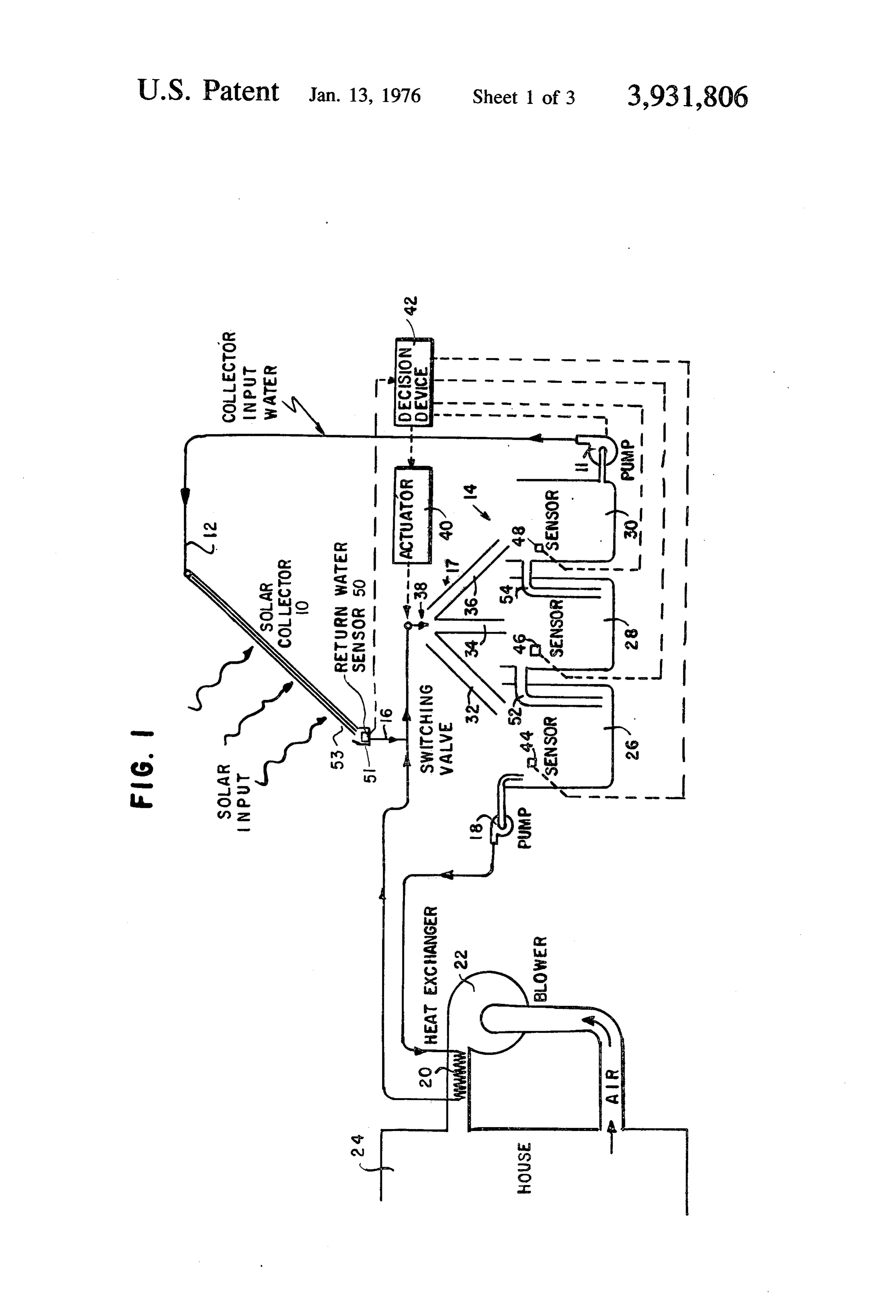
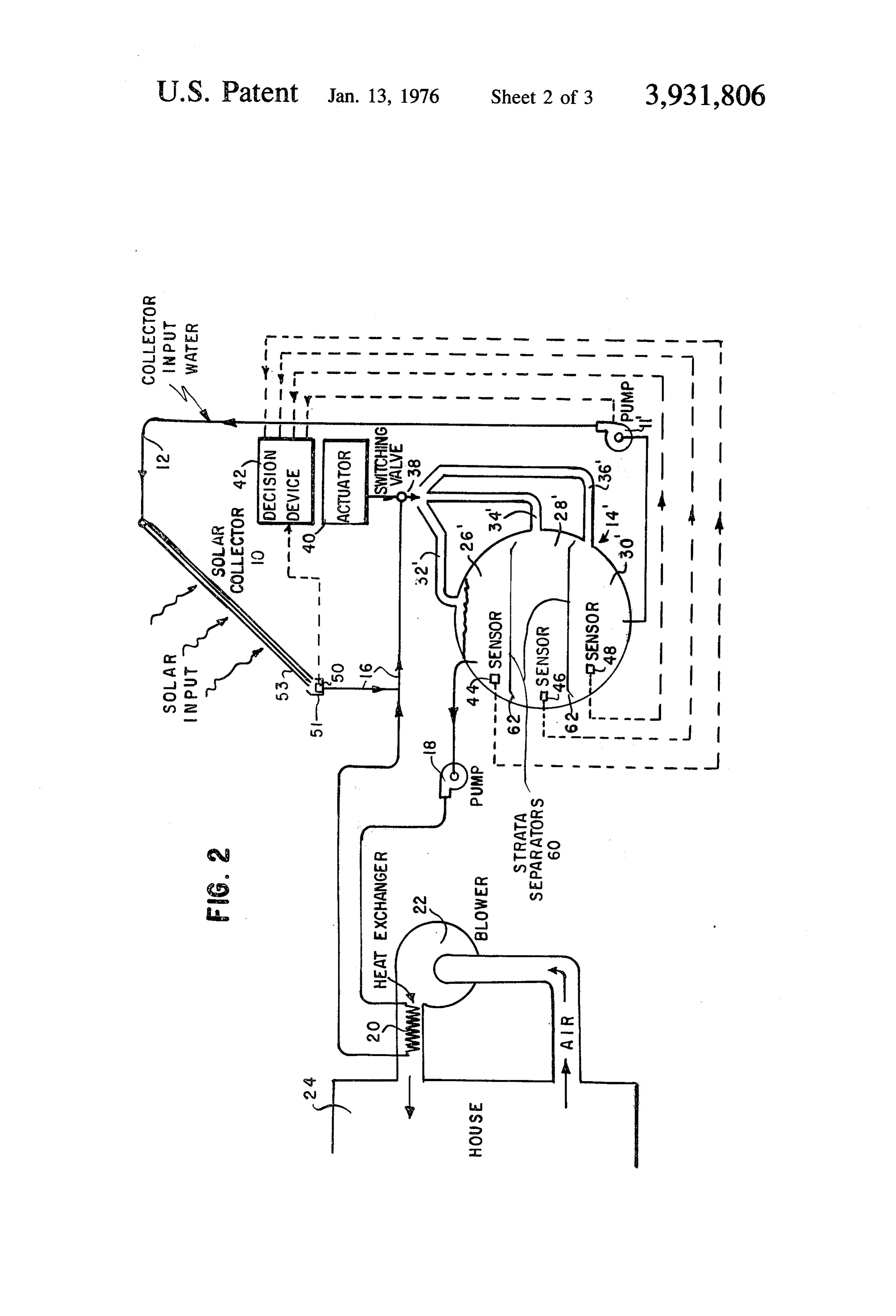
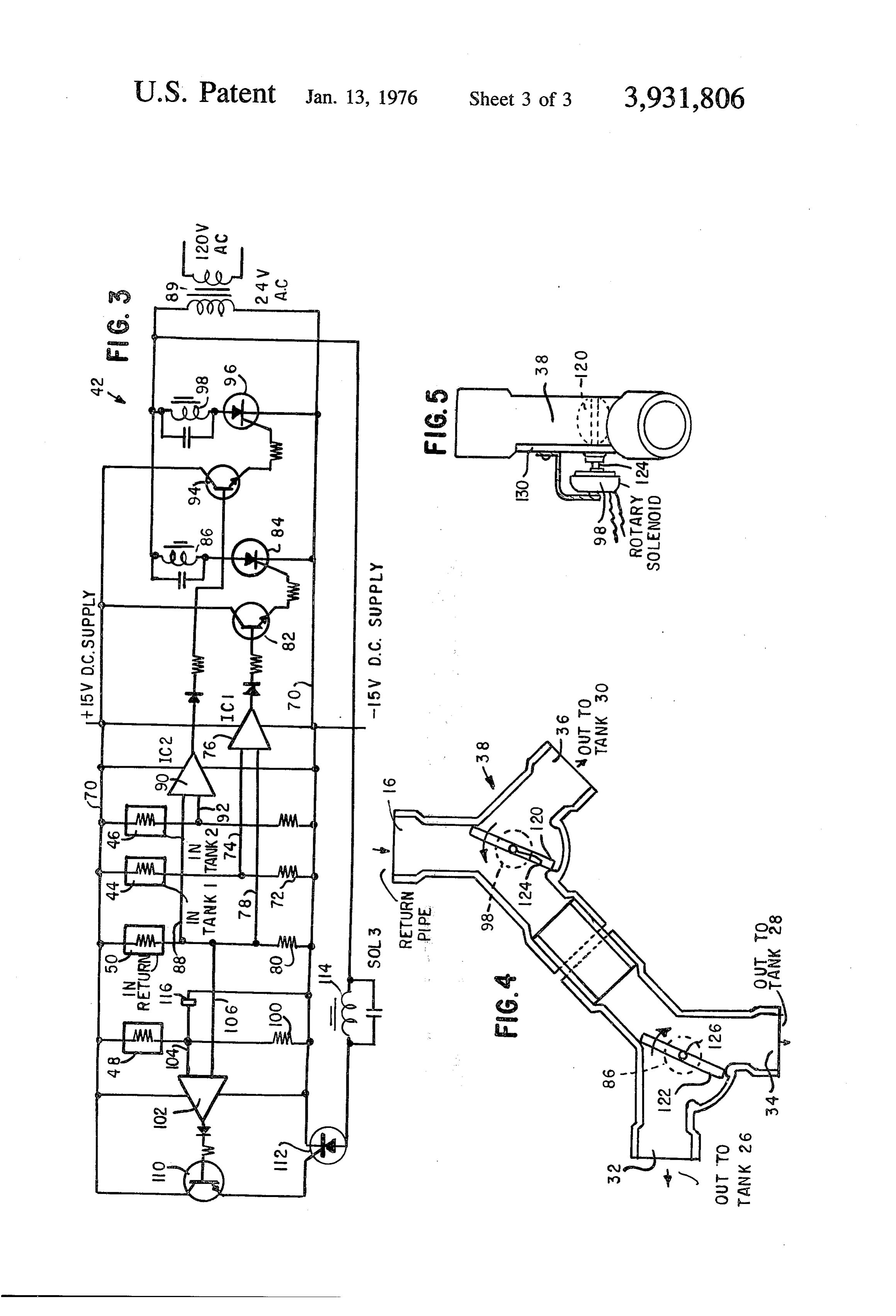
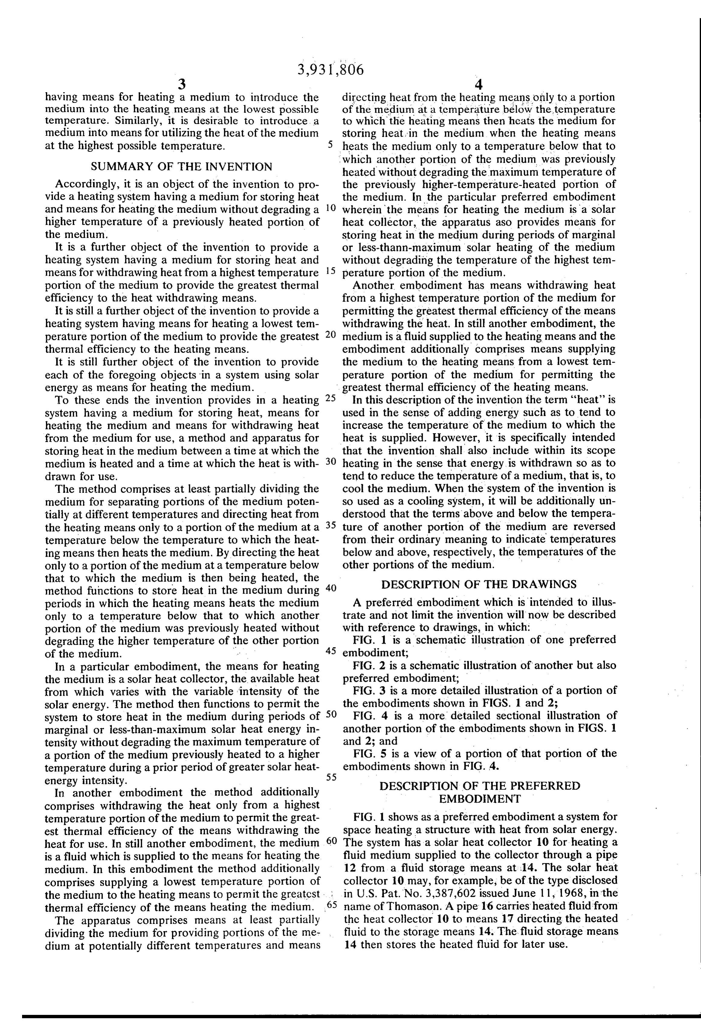
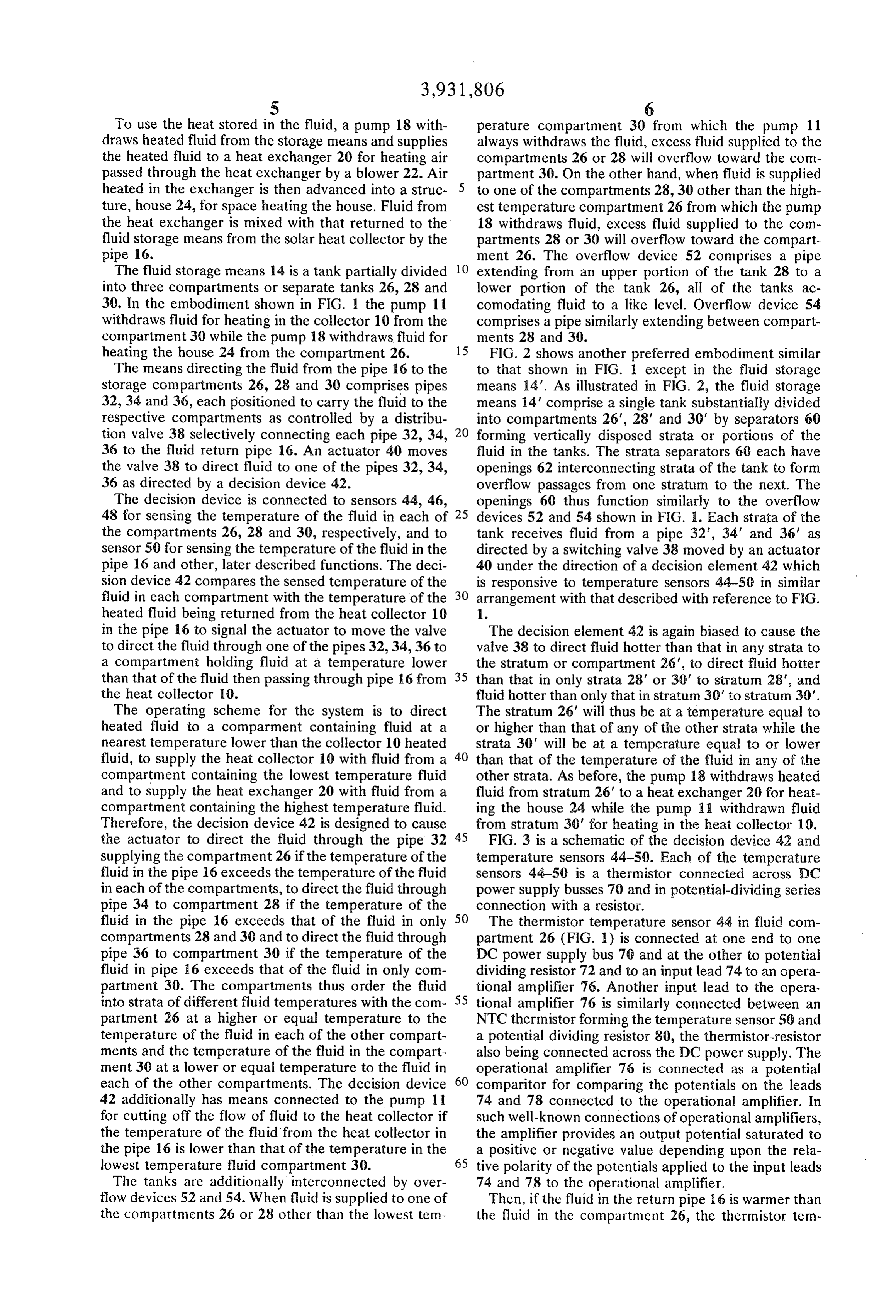
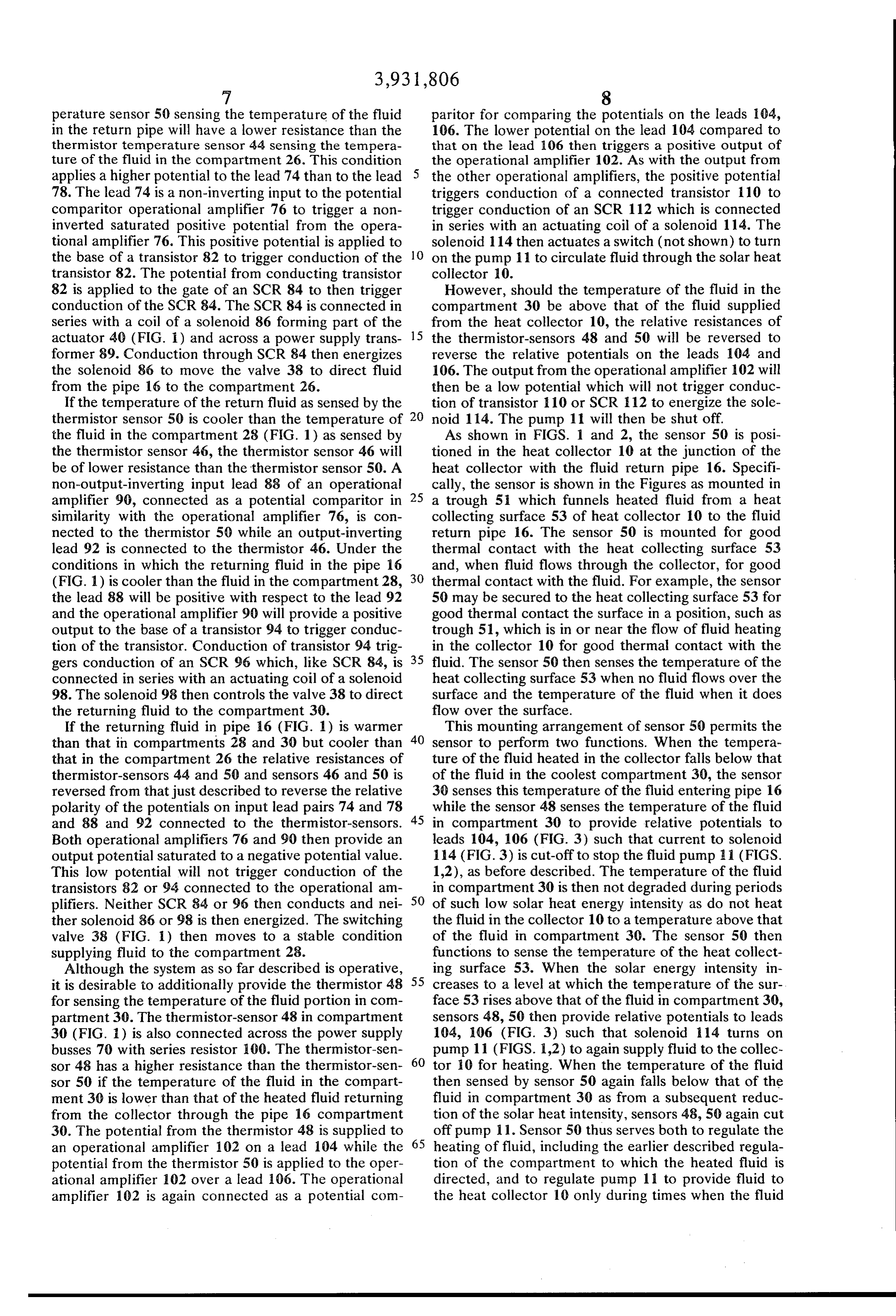
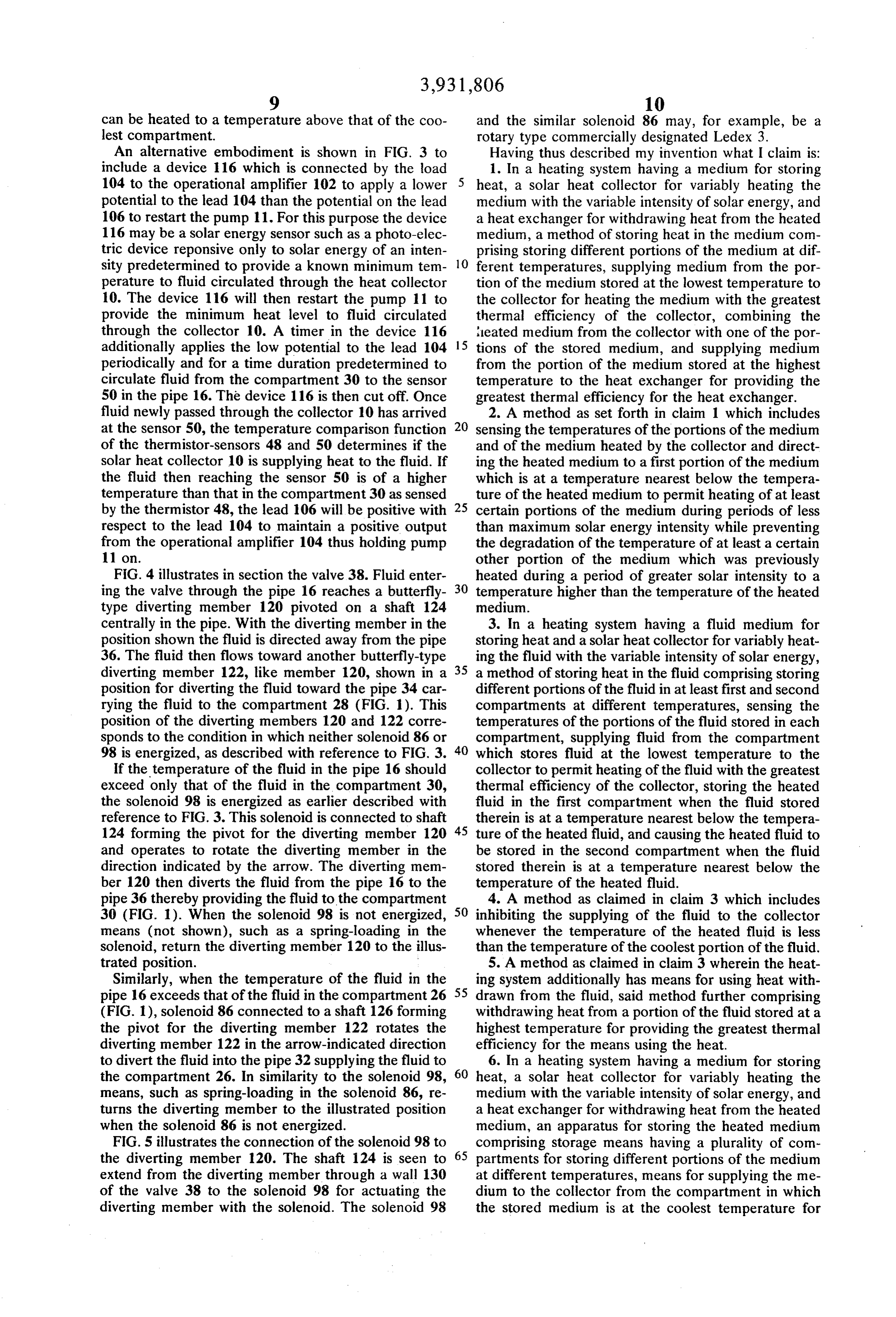
that to which the medium is then being heated, the 40 DESCRIPTION OF THE DRAWINGS method functions to store heat in the medium during periods in which the heating means heats the medium A preferred embodiment which is intended to illus only to a temperature below that to which another trate and not limit the invention will now be described portion of the medium was previously heated without with reference to drawings, in which: degrading the higher temperature of the other portion 45 FIG. 1 is a schematic illustration of one preferred of the medium. . embodiment; - In a particular embodiment, the means for heating FIG. 2 is a schematic illustration of another but also the medium is a solar heat collector, the available heat preferred embodiment;
from which varies with the variable intensity of the FIG. 3 is a more detailed illustration of a portion of solar energy. The method then functions to permit the 50 the embodiments shown in FIGS. 1 and 2; system to store heat in the medium during periods of FIG. 4 is a more detailed sectional illustration of marginal or less-than-maximum solar heat energy in another portion of the embodiments shown in FIGS. 1 tensity without degrading the maximum temperature of and 2; and a portion of the medium previously heated to a higher FIG. 5 is a view of a portion of that portion of the temperature during a prior period of greater solar heat 55 embodiments shown in FIG. 4.
energy intensity. DESCRIPTION OF THE PREFERRED In another embodiment the method additionally EMBODEMENT comprises withdrawing the heat only from a highest temperature portion of the medium to permit the great FIG. 1 shows as a preferred embodiment a system for est thermal efficiency of the means withdrawing the space heating a structure with heat from solar energy. heat for use. In still another embodiment, the medium 60 The system has a solar heat collector 10 for heating a is a fluid which is supplied to the means for heating the fluid medium supplied to the collector through a pipe medium. In this embodiment the method additionally 12 from a fluid storage means at 14. The solar heat comprises supplying a lowest temperature portion of collector 10 may, for example, be of the type disclosed the medium to the heating means to permit the greatest in U.S. Pat. No. 3,387,602 issued June 11, 1968, in the thermal efficiency of the means heating the medium. 65 name of Thomason. A pipe 16 carries heated fluid from The apparatus comprises means at least partially the heat collector 10 to means 17 directing the heated dividing the medium for providing portions of the me fluid to the storage means 14. The fluid storage means dium at potentially different temperatures and means 14 then stores the heated fluid for later use.
Page 7
S 6
To use the heat stored in the fluid, a pump 18 with perature compartment 30 from which the pump 11 draws heated fluid from the storage means and supplies always withdraws the fluid, excess fluid supplied to the the heated fluid to a heat exchanger 20 for heating air compartments 26 or 28 will overflow toward the com passed through the heat exchanger by a blower 22. Air partment 30. On the other hand, when fluid is supplied heated in the exchanger is then advanced into a struc to one of the compartments 28, 30 other than the high ture, house 24, for space heating the house. Fluid from est temperature compartment 26 from which the pump the heat exchanger is mixed with that returned to the 18 withdraws fluid, excess fluid supplied to the com fluid storage means from the solar heat collector by the partments 28 or 30 will overflow toward the compart pipe 16. ment 26. The overflow device 52 comprises a pipe The fluid storage means 14 is a tank partially divided 10 extending from an upper portion of the tank 28 to a into three compartments or separate tanks 26, 28 and lower portion of the tank 26, all of the tanks ac 30. In the embodiment shown in FIG. 1 the pump 11 comodating fluid to a like level. Overflow device 54 withdraws fluid for heating in the collector 10 from the comprises a pipe similarly extending between compart compartment 30 while the pump 18 withdraws fluid for ments 28 and 30.
heating the house 24 from the compartment 26. 15 FIG. 2 shows another preferred embodiment similar The means directing the fluid from the pipe 16 to the to that shown in FIG. except in the fluid storage storage compartments 26, 28 and 30 comprises pipes means 14'. As illustrated in FIG. 2, the fluid storage 32, 34 and 36, each positioned to carry the fluid to the means 4' comprise a single tank substantially divided respective compartments as controlled by a distribu into compartments 26", 28' and 30' by separators 60 tion valve 38 selectively connecting each pipe 32, 34, forming vertically disposed strata or portions of the 36 to the fluid return pipe 16. An actuator 40 moves fluid in the tanks. The strata separators 60 each have the valve 38 to direct fluid to one of the pipes 32, 34, openings 62 interconnecting strata of the tank to form 36 as directed by a decision device 42. overflow passages from one stratum to the next. The The decision device is connected to sensors 44, 46, openings 60 thus function similarly to the overflow 48 for sensing the temperature of the fluid in each of 25 devices 52 and 54 shown in FIG. I. Each strata of the the compartments 26, 28 and 30, respectively, and to tank receives fluid from a pipe 32, 34' and 36' as sensor 50 for sensing the temperature of the fluid in the directed by a switching valve 38 moved by an actuator pipe 16 and other, later described functions. The deci 40 under the direction of a decision element 42 which sion device 42 compares the sensed temperature of the is responsive to temperature sensors 44-50 in similar fluid in each compartment with the temperature of the 30 arrangement with that described with reference to FIG. heated fluid being returned from the heat collector 10 1.
in the pipe 16 to signal the actuator to move the valve The decision element 42 is again biased to cause the to direct the fluid through one of the pipes 32, 34, 36 to valve 38 to direct fluid hotter than that in any strata to a compartment holding fluid at a temperature lower the stratum or compartment 26', to direct fluid hotter than that of the fluid then passing through pipe 16 from 35 than that in only strata 28' or 30' to stratum 28', and the heat collector 10. fluid hotter than only that in stratum 30' to stratum 30'. The operating scheme for the system is to direct The stratum 26' will thus be at a temperature equal to heated fluid to a comparment containing fluid at a or higher than that of any of the other strata while the nearest temperature lower than the collector 10 heated strata 30' will be at a temperature equal to or lower fluid, to supply the heat collector 10 with fluid from a 40 than that of the temperature of the fluid in any of the compartment containing the lowest temperature fluid other strata. As before, the pump 18 withdraws heated and to supply the heat exchanger 20 with fluid from a fluid from stratum 26' to a heat exchanger 20 for heat compartment containing the highest temperature fluid. ing the house 24 while the pump 11 withdrawn fluid Therefore, the decision device 42 is designed to cause from stratum 30' for heating in the heat collector 10. the actuator to direct the fluid through the pipe 32 45 FIG. 3 is a schematic of the decision device 42 and supplying the compartment 26 if the temperature of the temperature sensors 44-50. Each of the temperature fluid in the pipe 16 exceeds the temperature of the fluid sensors 44-50 is a thermistor connected across DC in each of the compartments, to direct the fluid through power supply busses 70 and in potential-dividing series pipe 34 to compartment 28 if the temperature of the connection with a resistor.
fluid in the pipe 6 exceeds that of the fluid in only 50 The thermistor temperature sensor 44 in fluid com compartments 28 and 30 and to direct the fluid through partment 26 (FIG. 1) is connected at one end to one pipe 36 to compartment 30 if the temperature of the DC power supply bus 70 and at the other to potential fluid in pipe 6 exceeds that of the fluid in only com dividing resistor 72 and to an input lead 74 to an opera partment 30. The compartments thus order the fluid tional amplifier 76. Another input lead to the opera into strata of different fluid temperatures with the com 55 tional amplifier 76 is similarly connected between an partment 26 at a higher or equal temperature to the NTC thermistor forming the temperature sensor 50 and temperature of the fluid in each of the other compart a potential dividing resistor 80, the thermistor-resistor ments and the temperature of the fluid in the compart also being connected across the DC power supply. The ment 30 at a lower or equal temperature to the fluid in operational amplifier 76 is connected as a potential each of the other compartments. The decision device 60 comparitor for comparing the potentials on the leads 42 additionally has means connected to the pump 11 74 and 78 connected to the operational amplifier. In for cutting off the flow of fluid to the heat collector if such well-known connections of operational amplifiers, the temperature of the fluid from the heat collector in the amplifier provides an output potential saturated to the pipe 16 is lower than that of the temperature in the a positive or negative value depending upon the rela lowest temperature fluid compartment 30. 65 tive polarity of the potentials applied to the input leads The tanks are additionally interconnected by over 74 and 78 to the operational amplifier. flow devices 52 and 54. When fluid is supplied to one of Then, if the fluid in the return pipe 16 is warmer than the compartments 26 or 28 other than the lowest tem the fluid in the compartment 26, the thermistor tem
Page 8
perature sensor 50 sensing the temperature of the fluid paritor for comparing the potentials on the leads 104, in the return pipe will have a lower resistance than the 106. The lower potential on the lead 104 compared to thermistor temperature sensor 44 sensing the tempera that on the lead 106 then triggers a positive output of ture of the fluid in the compartment 26. This condition the operational amplifier 102. As with the output from applies a higher potential to the lead 74 than to the lead the other operational amplifiers, the positive potential 78. The lead 74 is a non-inverting input to the potential triggers conduction of a connected transistor 110 to comparitor operational amplifier 76 to trigger a non trigger conduction of an SCR 112 which is connected inverted saturated positive potential from the opera in series with an actuating coil of a solenoid 114. The tional amplifier 76. This positive potential is applied to solenoid 114 then actuates a switch (not shown) to turn the base of a transistor 82 to trigger conduction of the 10 on the pump 11 to circulate fluid through the solar heat transistor 82. The potential from conducting transistor collector 0.
82 is applied to the gate of an SCR 84 to then trigger However, should the temperature of the fluid in the conduction of the SCR 84. The SCR 84 is connected in compartment 30 be above that of the fluid supplied series with a coil of a solenoid 86 forming part of the from the heat collector 10, the relative resistances of actuator 40 (FIG. 1) and across a power supply trans 15 the thermistor-sensors 48 and 50 will be reversed to former 89. Conduction through SCR 84 then energizes reverse the relative potentials on the leads 104 and the solenoid 86 to move the valve 38 to direct fluid 106. The output from the operational amplifier 102 will from the pipe 16 to the compartment 26. then be a low potential which will not trigger conduc If the temperature of the return fluid as sensed by the tion of transistor 10 or SCR 12 to energize the sole thermistor sensor 50 is cooler than the temperature of 20 noid 114. The pump 11 will then be shut off. the fluid in the compartment 28 (FIG. 1) as sensed by As shown in FIGS. 1 and 2, the sensor 50 is posi the thermistor sensor 46, the thermistor sensor 46 will tioned in the heat collector 10 at the junction of the be of lower resistance than the thermistor sensor 50. A heat collector with the fluid return pipe 16. Specifi non-output-inverting input lead 88 of an operational cally, the sensor is shown in the Figures as mounted in amplifier 90, connected as a potential comparitor in 25 a trough 51 which funnels heated fluid from a heat similarity with the operational amplifier 76, is con collecting surface 53 of heat collector 10 to the fluid nected to the thermistor 50 while an output-inverting return pipe 6. The sensor 50 is mounted for good lead 92 is connected to the thermistor 46. Under the thermal contact with the heat collecting surface 53 conditions in which the returning fluid in the pipe 16 and, when fluid flows through the collector, for good (FIG. 1) is cooler than the fluid in the compartment 28, 30 thermal contact with the fluid. For example, the sensor the lead 88 will be positive with respect to the lead 92 50 may be secured to the heat collecting surface 53 for and the operational amplifier 90 will provide a positive good thermal contact the surface in a position, such as output to the base of a transistor 94 to trigger conduc trough 51, which is in or near the flow of fluid heating tion of the transistor. Conduction of transistor 94 trig in the collector 10 for good thermal contact with the gers conduction of an SCR 96 which, like SCR 84, is 35 fluid. The sensor 50 then senses the temperature of the connected in series with an actuating coil of a solenoid heat collecting surface 53 when no fluid flows over the 98. The solenoid 98 then controls the valve 38 to direct surface and the temperature of the fluid when it does the returning fluid to the compartment 30. flow over the surface.
If the returning fluid in pipe 6 (FIG. 1) is warmer This mounting arrangement of sensor 50 permits the than that in compartments 28 and 30 but cooler than 40 sensor to perform two functions. When the tempera that in the compartment 26 the relative resistances of ture of the fluid heated in the collector falls below that thermistor-sensors 44 and 50 and sensors 46 and 50 is of the fluid in the coolest compartment 30, the sensor reversed from that just described to reverse the relative 30 senses this temperature of the fluid entering pipe 16 polarity of the potentials on input lead pairs 74 and 78 while the sensor 48 senses the temperature of the fluid and 88 and 92 connected to the thermistor-sensors. 45 in compartment 30 to provide relative potentials to Both operational amplifiers 76 and 90 then provide an leads 104, 106 (FIG. 3) such that current to solenoid output potential saturated to a negative potential value. 114 (FIG. 3) is cut-off to stop the fluid pump 11 (FIGS. This low potential will not trigger conduction of the 1,2), as before described. The temperature of the fluid transistors 82 or 94 connected to the operational am 50 in compartment 30 is then not degraded during periods plifiers. Neither SCR 84 or 96 then conducts and nei of such low solar heat energy intensity as do not heat ther solenoid 86 or 98 is then energized. The switching the fluid in the collector 10 to a temperature above that valve 38 (FIG. 1) then moves to a stable condition of the fluid in compartment 30. The sensor 50 then supplying fluid to the compartment 28. functions to sense the temperature of the heat collect Although the system as so far described is operative, 55 ing surface 53. When the solar energy intensity in it is desirable to additionally provide the thermistor 48 creases to a level at which the temperature of the sur for sensing the temperature of the fluid portion in com face 53 rises above that of the fluid in compartment 30, partment 30. The thermistor-sensor 48 in compartment sensors 48, 50 then provide relative potentials to leads 30 (FIG. ) is also connected across the power supply 104, 106 (FIG. 3) such that solenoid 14 turns on busses 70 with series resistor 100. The thermistor-sen pump 11 (FIGS. 1,2) to again supply fluid to the collec sor 48 has a higher resistance than the thermistor-sen 60 tor 10 for heating. When the temperature of the fluid sor 50 if the temperature of the fluid in the compart then sensed by sensor 50 again falls below that of the ment 30 is lower than that of the heated fluid returning fluid in compartment 30 as from a subsequent reduc from the collector through the pipe 16 compartment tion of the solar heat intensity, sensors 48, 50 again cut 30. The potential from the thermistor 48 is supplied to 65 off pump 11. Sensor 50 thus serves both to regulate the an operational amplifier 102 on a lead 104 while the heating of fluid, including the earlier described regula potential from the thermistor 50 is applied to the oper tion of the compartment to which the heated fluid is ational amplifier 102 over a lead 106. The operational directed, and to regulate pump 11 to provide fluid to amplifier 102 is again connected as a potential com the heat collector 10 only during times when the fluid
Page 9
can be heated to a temperature above that of the coo and the similar solenoid 86 may, for example, be a lest compartment. rotary type commercially designated Ledex 3. An alternative embodiment is shown in FIG. 3 to Having thus described my invention what I claim is: include a device 116 which is connected by the load 1. In a heating system having a medium for storing 104 to the operational amplifier 102 to apply a lower 5 heat, a solar heat collector for variably heating the potential to the lead 104 than the potential on the lead medium with the variable intensity of solar energy, and 106 to restart the pump 11. For this purpose the device a heat exchanger for withdrawing heat from the heated 116 may be a solar energy sensor such as a photo-elec medium, a method of storing heat in the medium com tric device reponsive only to solar energy of an inten prising storing different portions of the medium at dif sity predetermined to provide a known minimum tem- 10 ferent temperatures, supplying medium from the por perature to fluid circulated through the heat collector tion of the medium stored at the lowest temperature to 10. The device 116 will then restart the pump 11 to the collector for heating the medium with the greatest provide the minimum heat level to fluid circulated thermal efficiency of the collector, combining the through the collector 10. A timer in the device 116 leated medium from the collector with one of the por additionally applies the low potential to the lead 104 15 tions of the stored medium, and supplying medium periodically and for a time duration predetermined to from the portion of the medium stored at the highest circulate fluid from the compartment 30 to the sensor temperature to the heat exchanger for providing the 50 in the pipe 16. The device 116 is then cut off. Once greatest thermal efficiency for the heat exchanger. fluid newly passed through the collector 10 has arrived 2. A method as set forth in claim 1 which includes at the sensor 50, the temperature comparison function 20 sensing the temperatures of the portions of the medium of the thermistor-sensors 48 and 50 determines if the and of the medium heated by the collector and direct solar heat collector 10 is supplying heat to the fluid. If ing the heated medium to a first portion of the medium the fluid then reaching the sensor 50 is of a higher which is at a temperature nearest below the tempera temperature than that in the compartment 30 as sensed ture of the heated medium to permit heating of at least by the thermistor 48, the lead 106 will be positive with 25 certain portions of the medium during periods of less respect to the lead 104 to maintain a positive output than maximum solar energy intensity while preventing from the operational amplifier 104 thus holding pump the degradation of the temperature of at least a certain 11 on. other portion of the medium which was previously FIG. 4 illustrates in section the valve 38. Fluid enter heated during a period of greater solar intensity to a ing the valve through the pipe 16 reaches a butterfly- 30 temperature higher than the temperature of the heated type diverting member 120 pivoted on a shaft 124 medium.
centrally in the pipe. With the diverting member in the 3. In a heating system having a fluid medium for position shown the fluid is directed away from the pipe storing heat and a solar heat collector for variably heat 36. The fluid then flows toward another butterfly-type ing the fluid with the variable intensity of solar energy, diverting member 122, like member 120, shown in a 35 a method of storing heat in the fluid comprising storing position for diverting the fluid toward the pipe 34 car different portions of the fluid in at least first and second rying the fluid to the compartment 28 (FIG. 1). This compartments at different temperatures, sensing the position of the diverting members 120 and 122 corre temperatures of the portions of the fluid stored in each sponds to the condition in which neither solenoid 86 or compartment, supplying fluid from the compartment 98 is energized, as described with reference to FIG. 3. 40 which stores fluid at the lowest temperature to the If the temperature of the fluid in the pipe 16 should collector to permitheating of the fluid with the greatest exceed only that of the fluid in the compartment 30, thermal efficiency of the collector, storing the heated the solenoid 98 is energized as earlier described with fluid in the first compartment when the fluid stored reference to FIG. 3. This solenoid is connected to shaft therein is at a temperature nearest below the tempera 124 forming the pivot for the diverting member 120 45 ture of the heated fluid, and causing the heated fluid to and operates to rotate the diverting member in the be stored in the second compartment when the fluid direction indicated by the arrow. The diverting mem stored therein is at a temperature nearest below the ber 120 then diverts the fluid from the pipe 16 to the temperature of the heated fluid.
pipe 36 thereby providing the fluid to the compartment 4. A method as claimed in claim 3 which includes 30 (FIG. 1). When the solenoid 98 is not energized, 50 inhibiting the supplying of the fluid to the collector means (not shown), such as a spring-loading in the whenever the temperature of the heated fluid is less solenoid, return the diverting member 120 to the illus than the temperature of the coolest portion of the fluid. trated position. 5. A method as claimed in claim 3 wherein the heat Similarly, when the temperature of the fluid in the ing system additionally has means for using heat with pipe 16 exceeds that of the fluid in the compartment 26 55 drawn from the fluid, said method further comprising (FIG. 1), solenoid 86 connected to a shaft 126 forming withdrawing heat from a portion of the fluid stored at a the pivot for the diverting member 122 rotates the highest temperature for providing the greatest thermal diverting member 122 in the arrow-indicated direction efficiency for the means using the heat. to divert the fluid into the pipe 32 supplying the fluid to 6. In a heating system having a medium for storing the compartment 26. In similarity to the solenoid 98, 60 heat, a solar heat collector for variably heating the means, such as spring-loading in the solenoid 86, re medium with the variable intensity of solar energy, and turns the diverting member to the illustrated position a heat exchanger for withdrawing heat from the heated when the solenoid 86 is not energized. medium, an apparatus for storing the heated medium FIG. 5 illustrates the connection of the solenoid 98 to comprising storage means having a plurality of com the diverting member 120. The shaft 124 is seen to 65 partments for storing different portions of the medium extend from the diverting member through a wall 130 at different temperatures, means for supplying the me of the valve 38 to the solenoid 98 for actuating the dium to the collector from the compartment in which diverting member with the solenoid. The solenoid 98 the stored medium is at the coolest temperature for
Page 10
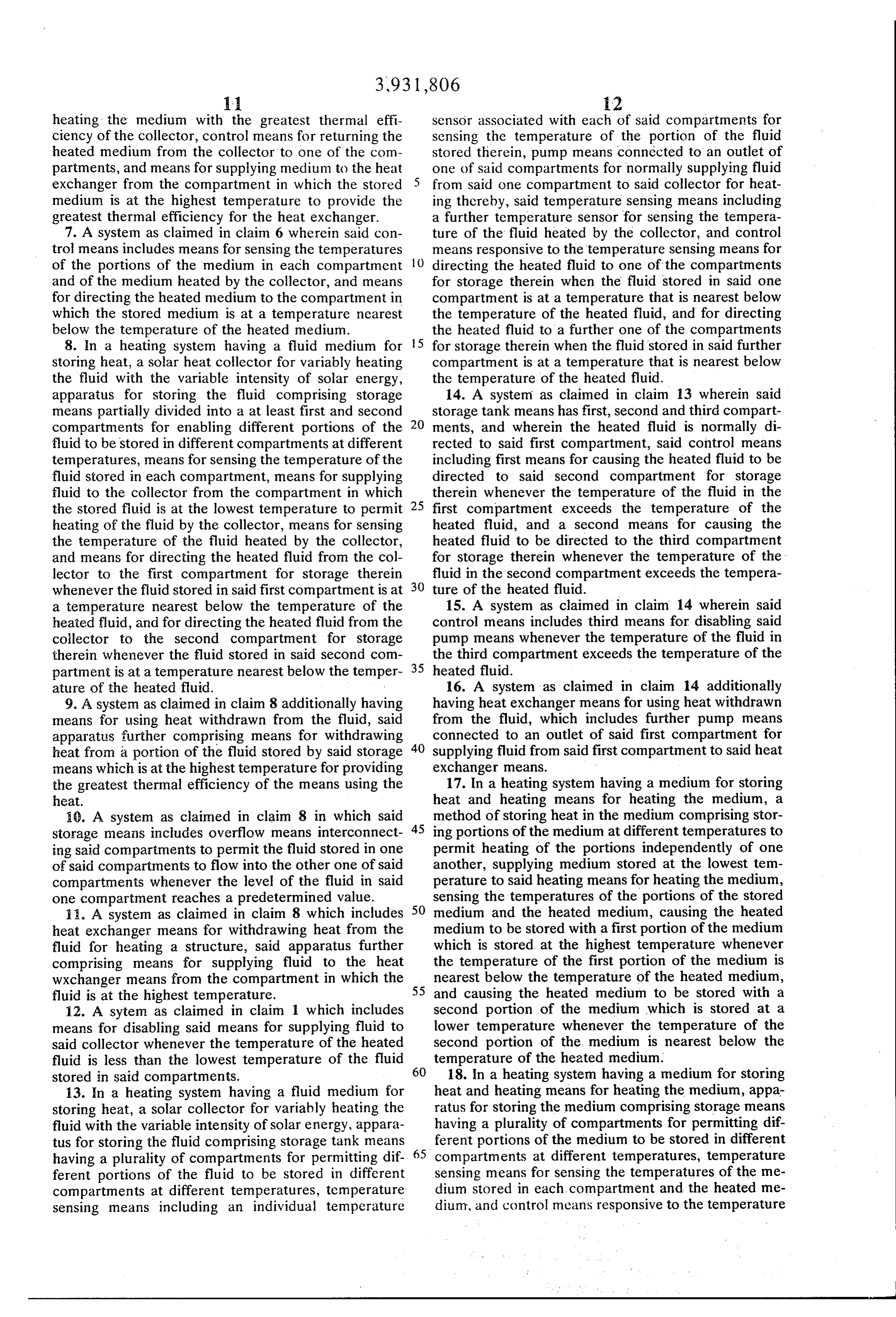
heating the medium with the greatest thermal effi sensor associated with each of said compartments for ciency of the collector, control means for returning the sensing the temperature of the portion of the fluid heated medium from the collector to one of the com stored therein, pump means connected to an outlet of partments, and means for supplying medium to the heat one of said compartments for normally supplying fluid exchanger from the compartment in which the stored 5 from said one compartment to said collector for heat medium is at the highest temperature to provide the ing thereby, said temperature sensing means including greatest thermal efficiency for the heat exchanger. a further temperature sensor for sensing the tempera 7. A system as claimed in claim 6 wherein said con ture of the fluid heated by the collector, and control trol means includes means for sensing the temperatures means responsive to the temperature sensing means for of the portions of the medium in each compartment 10 directing the heated fluid to one of the compartments and of the medium heated by the collector, and means for storage therein when the fluid stored in said one for directing the heated medium to the compartment in compartment is at a temperature that is nearest below which the stored medium is at a temperature nearest the temperature of the heated fluid, and for directing below the temperature of the heated medium. the heated fluid to a further one of the compartments 8. In a heating system having a fluid medium for 5 for storage therein when the fluid stored in said further storing heat, a solar heat collector for variably heating compartment is at a temperature that is nearest below the fluid with the variable intensity of solar energy, the temperature of the heated fluid. apparatus for storing the fluid comprising storage 14. A system as claimed in claim 13 wherein said means partially divided into a at least first and second 20 storage tank means has first, second and third compart compartments for enabling different portions of the ments, and wherein the heated fluid is normally di fluid to be stored in different compartments at different rected to said first compartment, said control means temperatures, means for sensing the temperature of the including first means for causing the heated fluid to be fluid stored in each compartment, means for supplying directed to said second compartment for storage fluid to the collector from the compartment in which 25 therein whenever the temperature of the fluid in the the stored fluid is at the lowest temperature to permit first compartment exceeds the temperature of the heating of the fluid by the collector, means for sensing heated fluid, and a second means for causing the the temperature of the fluid heated by the collector, heated fluid to be directed to the third compartment and means for directing the heated fluid from the col for storage therein whenever the temperature of the lector to the first compartment for storage therein fluid in the second compartment exceeds the tempera whenever the fluid stored in said first compartment is at 30 ture of the heated fluid.
a temperature nearest below the temperature of the 15. A system as claimed in claim 14 wherein said heated fluid, and for directing the heated fluid from the control means includes third means for disabling said collector to the second compartment for storage pump means whenever the temperature of the fluid in therein whenever the fluid stored in said second com the third compartment exceeds the temperature of the partment is at a temperature nearest below the temper 35 heated fluid.
ature of the heated fluid. 16. A system as claimed in claim 14 additionally 9. A system as claimed in claim 8 additionally having having heat exchanger means for using heat withdrawn means for using heat withdrawn from the fluid, said from the fluid, which includes further pump means apparatus further comprising means for withdrawing connected to an outlet of said first compartment for heat from a portion of the fluid stored by said storage 40 supplying fluid from said first compartment to said heat means which is at the highest temperature for providing exchanger means.
the greatest thermal efficiency of the means using the 17. In a heating system having a medium for storing heat. heat and heating means for heating the medium, a i0. A system as claimed in claim 8 in which said method of storing heat in the medium comprising stor storage means includes overflow means interconnect 45 ing portions of the medium at different temperatures to ing said compartments to permit the fluid stored in one permit heating of the portions independently of one of said compartments to flow into the other one of said another, supplying medium stored at the lowest tem compartments whenever the level of the fluid in said perature to said heating means for heating the medium, one compartment reaches a predetermined value. sensing the temperatures of the portions of the stored 11. A system as claimed in claim 8 which includes 50 medium and the heated medium, causing the heated heat exchanger means for withdrawing heat from the medium to be stored with a first portion of the medium fluid for heating a structure, said apparatus further which is stored at the highest temperature whenever comprising means for supplying fluid to the heat the temperature of the first portion of the medium is wxchanger means from the compartment in which the 55 nearest below the temperature of the heated medium, fluid is at the highest temperature. and causing the heated medium to be stored with a 12. A sytem as claimed in claim 1 which includes second portion of the medium which is stored at a means for disabling said means for supplying fluid to lower temperature whenever the temperature of the said collector whenever the temperature of the heated second portion of the medium is nearest below the fluid is less than the lowest temperature of the fluid 60 temperature of the heated medium. stored in said compartments. 18. In a heating system having a medium for storing 13. In a heating system having a fluid medium for heat and heating means for heating the medium, appa storing heat, a solar collector for variably heating the ratus for storing the medium comprising storage means fluid with the variable intensity of solar energy, appara having a plurality of compartments for permitting dif tus for storing the fluid comprising storage tank means 65 ferent portions of the medium to be stored in different having a plurality of compartments for permitting dif compartments at different temperatures, temperature ferent portions of the fluid to be stored in different sensing means for sensing the temperatures of the me compartments at different temperatures, temperature dium stored in each, compartment and the heated me sensing means including an individual temperature dium, and control means responsive to the temperature
Page 11
sensing means for directing the heated medium from the compartments for storage therein when the me the heating means to one of the compartments for dium stored in said further compartment is at a temper storage therein when the medium stored in said one ature nearest below the temperature of the heated compartment is at a temperature that is nearest below the temperature of the heated medium, said control 5 medium.
means directing the heated medium to a further one of ck k : :: *k
Page 12
UNITED STATES PATENT AND TRADEMARK of FICE
CERTIFICATE OF CORRECTION
INVENTOR(S) . Thomas Edward Hayes
It is Certified that error appears in the above-identified patent and that said Letters Patent are hereby corrected as shown below:
eigned and Sealed this twenty-fifth Day of May 1976
SEAL
attest
RUTH C. MASON C. MARSHALL D ANN At testing Officer Commissioner of Patents and Trademarks
Provenance
- Collection
- Cited prior art
- Original PDF
- patentimages.storage.googleapis.com →
- Filed
- 1974-05-06
- Pages
- 12
- Method
- pdftotext (the PDF's own text layer) + pdftoppm 300dpi page scans
- Source
- Google Patents bibliographic record
- Granted
- 1976-01-13
- Inventors
- Thomas Edward Hayes; Johnson Service Co
- Transcribed from
- patentimages.storage.googleapis.com →