patent · US5714665
Method and apparatus for the decomposition and re-use-as-resource treatment of ozone layer-depleting substances by application of UV light
3 February 1998
Page 1 — bibliographic record
ates Patent 19 11 Patent Number: 5,714,665
FOREIGN PATENT DOCUMENTS
REsouRC 10/1993 Japan.
LAYER-DEP ING SUBSTANCES BY 11/1991 United Kingdom ..... 204/157.3 APPLICATION OF UW LIGHT Primary Examiner. Arun S. Phasge
Attorney, Agent, or Firm. Flynn. Thiel, Boutell & Tanis, 75 Inventors: Kuninobu Ohtake; Takeshi Ohyama, PC, both of Yokohanna; Hisashi Sakai, 57 ABSTRACT
Kyoto, Xingzhe o, Kyoto; Shigeru
Morikawa, Kyoto, all of Japan A method for continuously decomposing OZOne layer depleting substances which comprises adding air serving as 73 Assignee: The Tokyo Electric Power Co., Inc., a photolytic reaction promoter to at least one member Tokyo, Japan selected from the group consisting of CFCs, HCFCs, halons and halogen-containing Organic solvents. Subjecting the 21 Appl. No.: 394,007 resultant mixture to irradiation with UV light, and separating the resultant solid product and the resultanthalogen product 22 Filled: Feb. 23, 1995 from each other to render the at least one member harmless (51 Int. Cl. ... B01, 2000 is described. The method comprises providing a refrigera 52 U.S. C. . 8/204; 588/2 15; tion medium comprising a lubricating oil and the at least one 20415 member, separating the lubricating oil from the at least one
member under normal temperature and normal pressure 58 Field of Search .................... conditions, separating moisture to a full extent from a 88,204.205:42 mixture consisting of the at least one merchber and air, and 56 References Cited subjecting the mixture to photolytic reaction by irradiation with UV light, and separating and collecting the resultant
apparatus for carrying out the method is also described.
5,260,036 l/1993 Weigold et al. ... 6 Clains, 9 Drawing Sheets
FLLFRCCARBON ...
CECTOR
(CAR AR ""
CNNER
ANO
GERATO ---------* FLuc RocARBON "FEMWiN
AND BFICATING UNT
JBFCANG Ol.
CEFR CFC
Page 2
Drawing sheet — no readable text.
Page 3
Drawing sheet — no readable text.
Page 4
Drawing sheet — no readable text.
Page 5
Drawing sheet — no readable text.
Page 6
Drawing sheet — no readable text.
Page 7
Drawing sheet — no readable text.
Page 8
Drawing sheet — no readable text.
Page 9
TTS Pafand- M' r th. 9 i? al"try'll h/
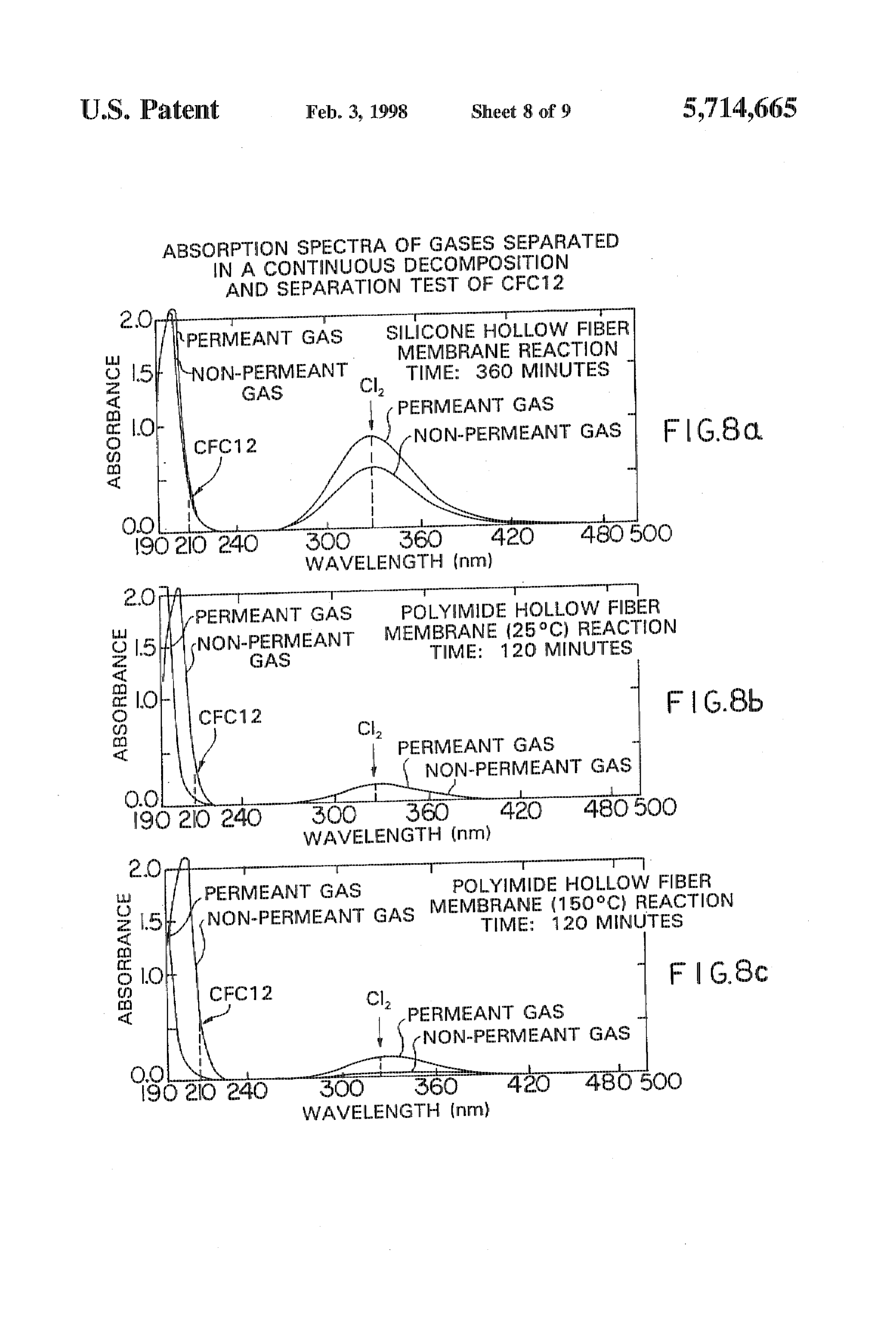
ABSORPTION SPECTRA OF GASES SEPARATED
IN A CONTINUOUS DECOMPOSETION
AND SEPARATION TEST OF CFC 12
2 O f -T-T-.--- raremeansmur
| PERMEANT GAS SILICONE HOLLOW FIBER
MEMEFESN
TIME: 360 MINUTES
MIDE HOLLOW FIBER
GAS EANT MEMBRANE (25°C)
TIME: 120 REACTION
MINUTES
| PERMEANT GAS ot-m-re.
POLYMIDE HOLLOW FIBER
MEME RANE (15OC) REACTION
dG.S. lo d NON-PERMEANT GAS TIME: 120h MINUTES imp, grin
CFC 12 C F. G.8c
PERMEANT GAS
WAVELENGTH (rim)
Page 10
Drawing sheet — no readable text.
Page 11
1 t
METEOD AND APPARATUS FOR THE ration membrane. These methods and apparatuses are par. DECOMPOSITION AND REUSEAS. ticularly set out in Japanese Patent Laid-Open Publication RESOURCE TREATMENT OF OEONE No. 5.277,205
LAYER-DEPLETING SUBSTANCES BY These patent applications deal with methods and appara APPLICATION OF UW LIGET 5 tuses for continuously decomposing and separating OZone layer-depleting substances without resorting to any chemical
BACKGROUND OF THE INVENTION treatment. However, any decomposition and re-use systern has never been established wherein a variety of ozone 1. Field of the Invention layer-depleting substances used in various fields are col This invention relates to a system for the decornposition 1. lected or recovered and are Subjected to continuous deCOI). and re-use-as-resource treatments of CFCs bromine position and separation treatment, after which the decom: containing halogenated fluorocarbons (hereinafter referred posed products are collected for re-use as a resource, to as, halons). HCFCs and other ozone layer-depleting SUMMARY OF THE INVENTION substances such as halogen-containing organic Solvents.
These substances including CFCs Inay be generically called It is accordingly an object of the invention to provide a ozone layer-depleting substances. More particularly, the fluorocarbon-decomposing and re-using system. Which invention relates to a method and apparatus for efficiently makes use of UV light whereby the systern can be estab decomposing ozone layer-depleting Substances by the use of lished for practical applications.
UV light for the re-use of the resultant decomposition O It is another object of the invention to provide a method products as kinds of resources. and apparatus for continuously decomposing a variety of 2. Description of The Prior Art ozone layer-depleting substances without resorting to any It has been generally accepted that CFC which has been specific chemical treatment under treating conditions close used in freezers, refrigerators, air-conditioners and aerosols to normal pressures whereby the ozone layer-depleting and also in washing of electronic parts CIC for dry cleaning is 25 substances are rendered harmless and the resultant decomi released in air and the thus released CFC rises up to the posed products can be re-used as kinds of resources. stratosphere wherein it is photodissociated by the action of It is a further object of the invention to provide a method sunlight and the resultant chlorine atoms destroy the ozone and apparatus for continuously decomposing a variety of layer therewith. Moreover, it has been reported that the ozone layer-depleting substances under good Working con sectional area of infrared ray absorption per Emolecule of 30 ditions by a simple mariner
CFC is greater by approximately two orders of magnitude The above objects can be achieved, according to one than that per CO molecule and that the anathermal effect of embodiment of the invention, by a method for continuously the earth resulting from CFC is as great as 10,000 to 20,000 decomposing CZone layer-depleting substances which con times that based on CO. per molecule, prises adding air serving as a photolyric reaction promoter to To avoid this, it has been advocated to reduce the amount 35 at least one member selected from the group consisting of of CFC used. The current CFC-saving measures include a CFCs, HCFCs, halons and halogen-Containing organic method for suppressing the release in air and a CFC alter solvents, subjecting the resultant mixture to irradiation with nating method. The release-suppressing method may be UV light, and separating the resultant Solid product and the classified into (a) a collection arid re-use method acid (b) a resultant halogen product from each other to render the at decomposition method. The decomposition of once used 40 east one member harnless, characterized by providing a CFC is believed to be a real measure. In fact, a variety of refrigeration medium comprising a lubricating oil and the at fluorocarbon decomposing methods have been studied up to least one member, separating the lubricating oil from the at now but have never been put into practice, least one member under normal temperature and normal At the treaty conference of Montreal's Protocol in 1992, pressure conditions, separating moisture to a full extent from which is a regulation treaty for OZone layer-depleting 45 a mixture consisting of the at least one member and air, and substances, it was determined that the fundanciental produc subjecting the mixture to photolytic reaction using UV light, tion of HCFC would be wholly abolished before 2020. On and separating and collecting the resultant halogen corn the other hand, although HFC does not contribute to destroy. pound from the photolytic reaction product. ing the ozone layer, it greatly influences the anathermal According to another embodiment of the invention, there tendency of the earth. Accordingly, it is assumed that HFC SO is also provided an apparatus for continuously decomposing will suffer some regulations in the future. Especially ozone layer-depleting Substances whereirl at least one mern HCFC22 has beer employed in domestic air conditioners ber selected from the group consisting of CFCs, HCFCs, over approximately 20 years and has been currently manu halons and halogen-containing Organic Solvents is provided factured in an armount of not less than 30,000 tons a year in acid admixed with air serving as a photolytic reaction Japan. The conversion of the HCFC into innoxious sub 55 promoter and is then subjected to irradiation with UV light stances has been a serious problem to solve next to that of to separate the resultant solid product and a halogen product CFC. Accordingly, the conversion, into harmless Substances, from each other to render the at least one member harnless, of HCFCs such as HCFC and HCF, will contribute to the the apparatus comprises a gas-liquid separator for a refr.ig. conservation of the terrestrial environment. eration medium containing a lubricating oil and at the least We already proposed methods and apparatuses for co one member wherein a lubricant oil is separated and tinuously decomposing and Separating Zone layer removed from the at least one member under normal tem. depleting substances wherein a continuously feeding gas perature and normal pressure conditions, a unit for feeding eous fluorocarbon is irradiated with UV light having a air added as a photolytic reaction promoter, a moisture specific wavelength at which the highest decomposition rate separator for completely separating and renoving moisture can be attained so that the fluorocarbor is decomposed and 65 from the at least one member and the air which are, the resultant reaction product and an unreacted fluorocarbon respectively, fed from the gas-liquid separator and the unit, are continuously separated from each other through a sepal a photolytic reactor having a UV light irradiator unit to
Page 12
which the fluorocarbon and air from which the moisture has alternate fluorocarbon HFC (134a: CHFCF), halogen been coincipletely separated therefrom are supplied, a sepa containing organic solvents (carbon tetrachloride, 1,1,1- rator for separating a gaseous or liquid halogen compound trichloroethane, trichloroethylene), and the like. formed by photolyric reaction from a reaction system, and a It will be noted that when HFC is decomposed, it is halogen collecting and storing unit wherein the separated 5 necessary to use UV light having a wavelength different halogen compound is collected and the at least one fluoro from that used for the other ozone layer-depleting sub carbon continuously fed to the apparatus. Stances.
For example, the optimum wavelength of the decompo
BRIEF DESCRIPTION OF THE DRAWINGS sition of HFC 134 becomes 102 nm when calculating
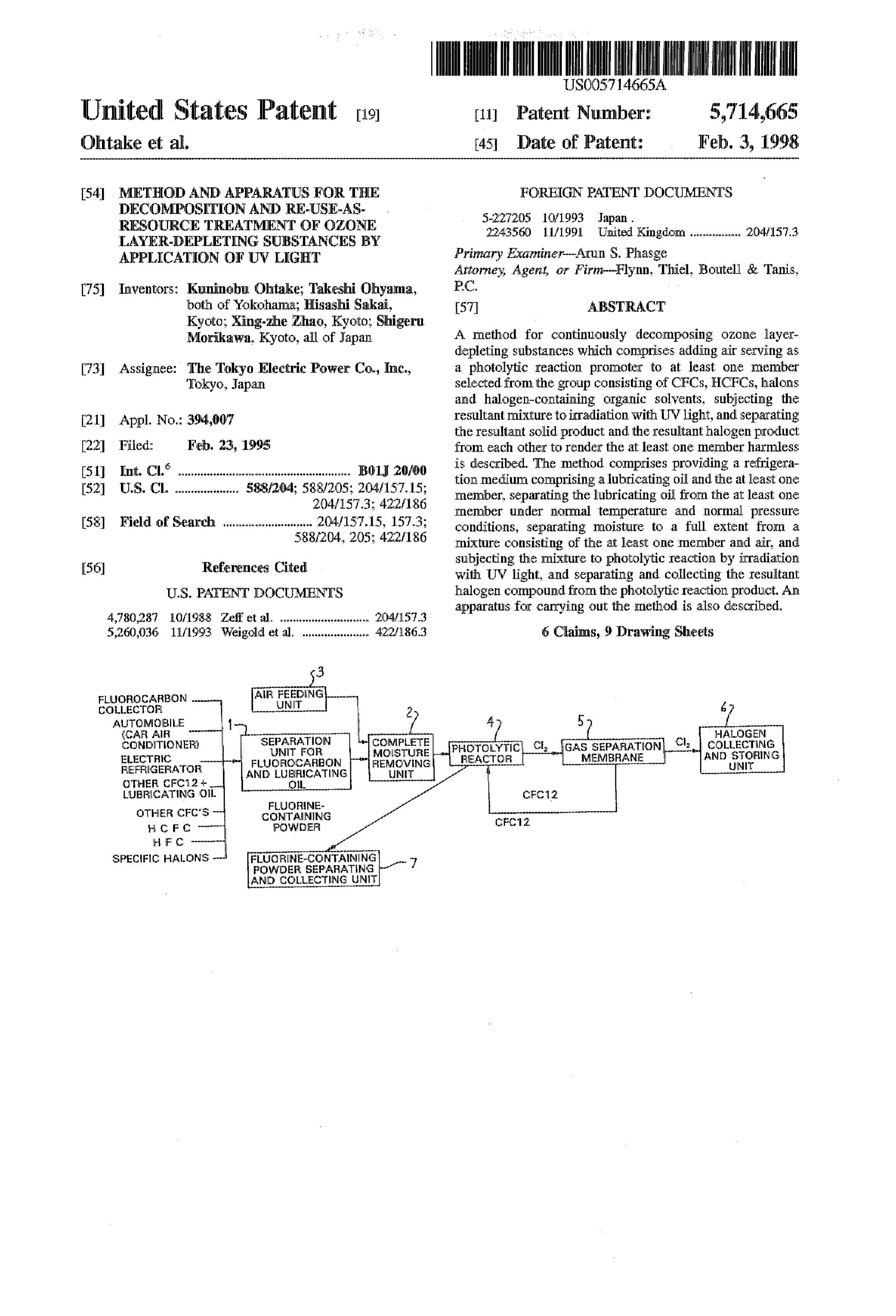
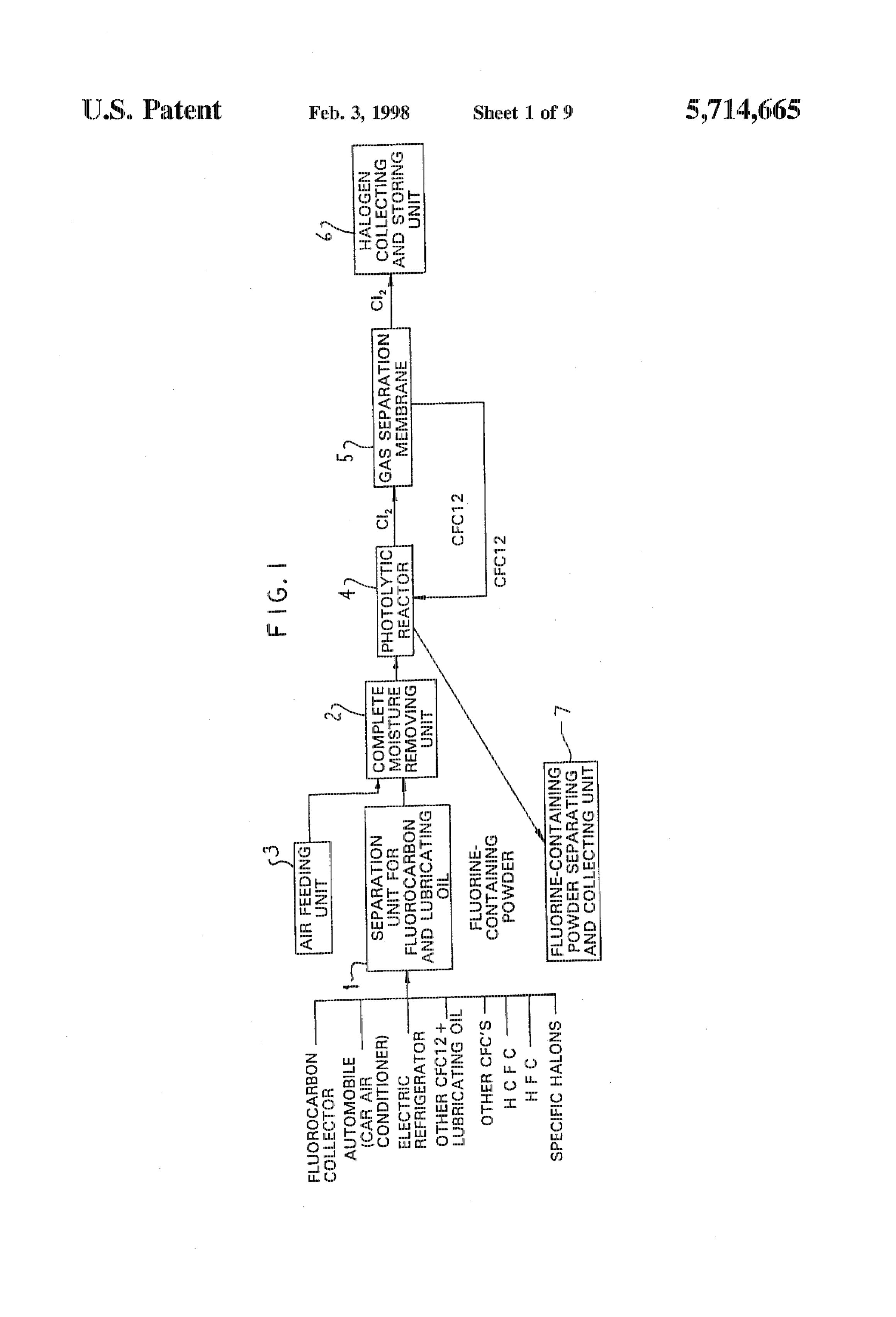
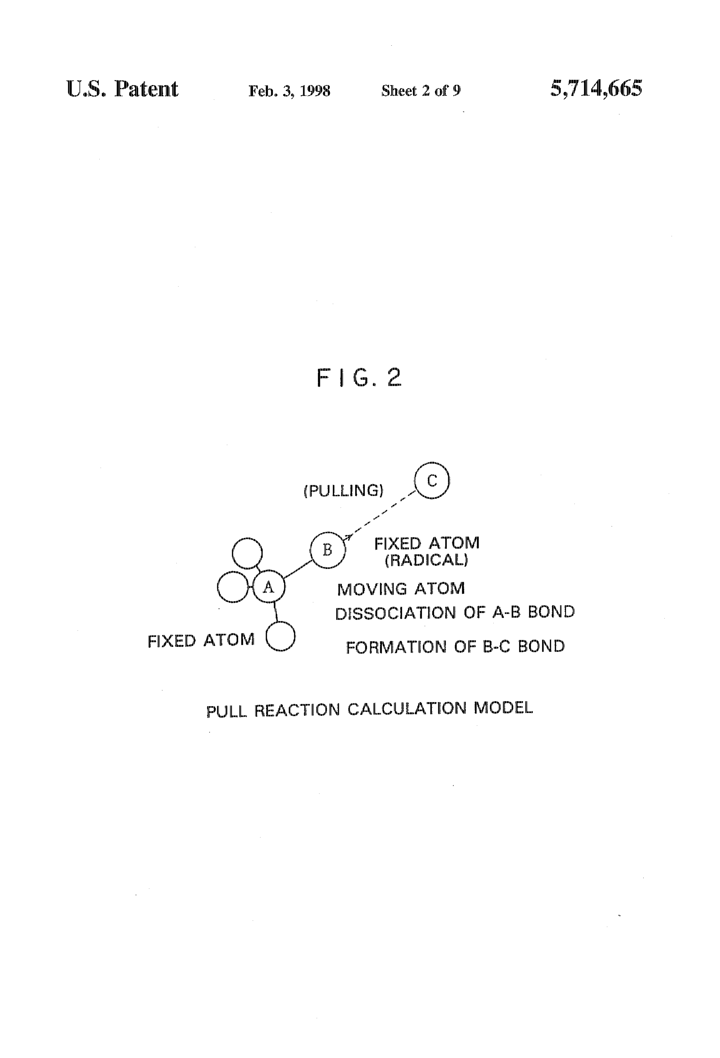
FIG. 1 is a flow chart showing a fluorocarbon (3-210) the HFC134ausing the non-experimental molecular decomposing and re-using systern according to an embodi orbital method (Gaussian, 92, Gaussian, Inc.). ment of the invention; According to the invention, lubricants which are con FIG. 2 is a schematic view showing an atom pull reaction which tained in ozone layer-depleting substances to be treated and model; 15 have the possibility of generating harmful substances FIG. 3 is a schematic view showing a complete separator on irradiation with UV light are first separated and removed under normal temperature and normal pressure conditions.
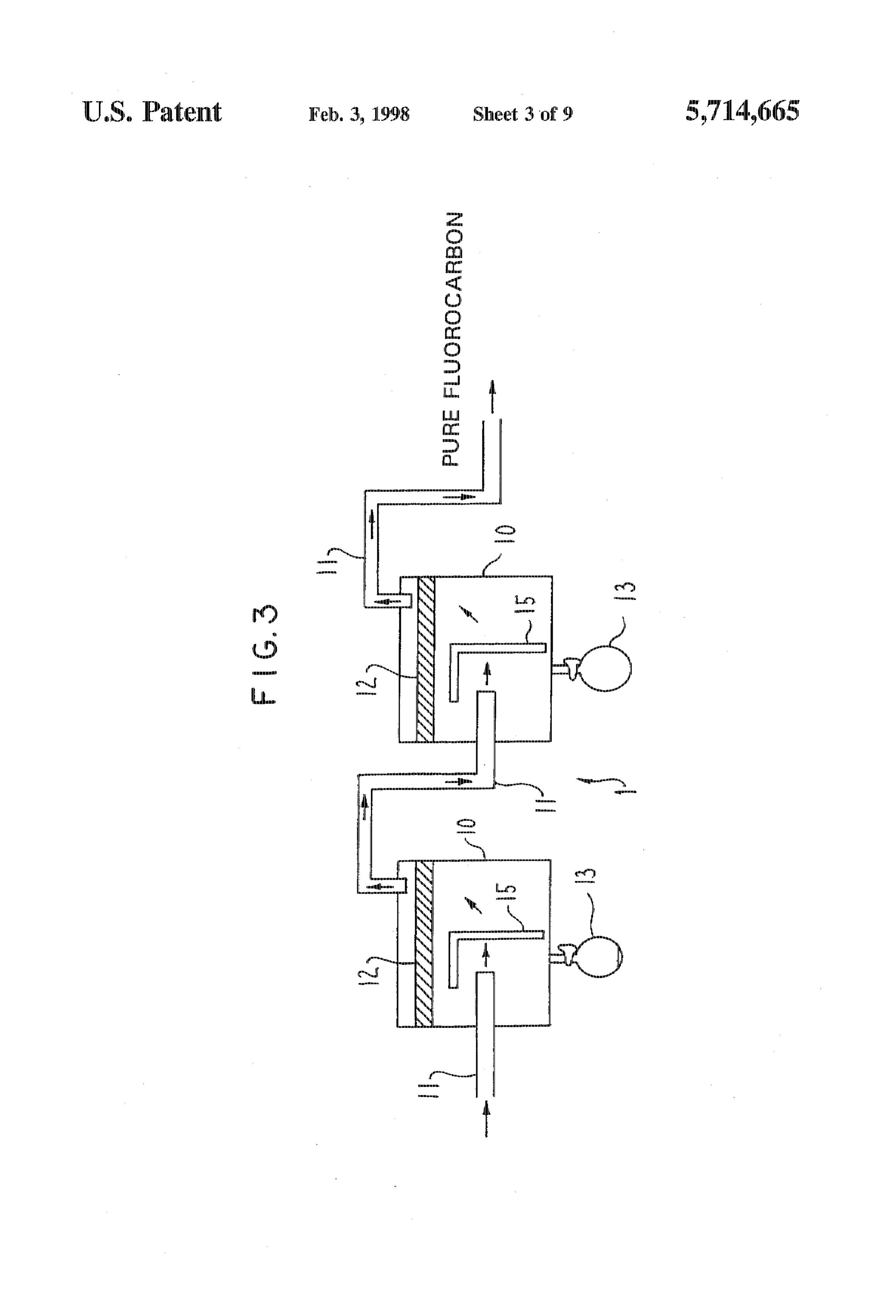
for a fluorocarbon and a lubricant oil used in an embodiment of the invention; Then, the thus removed fluorocarbon is subjected a pho tolytic reaction wherein oxygen in the air is used as a
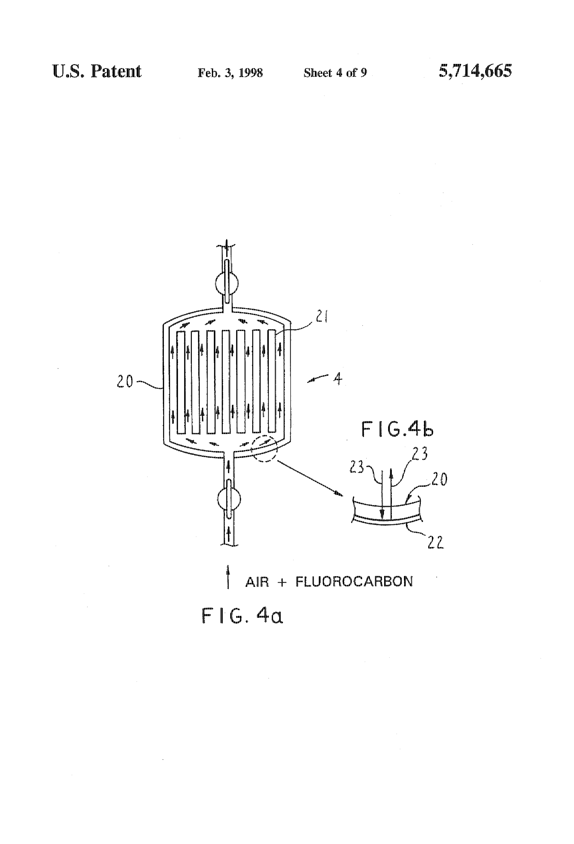
FIG. 4a is a schematic view showing a photolytic reactor photolytic reaction promoting substance or promoter. The used in an embodiment of the invention and FIG. 4 is an use of air as an oxygen source is convenient from the enlarged view showing a UV light reflecting film formed on standpoint of costs.
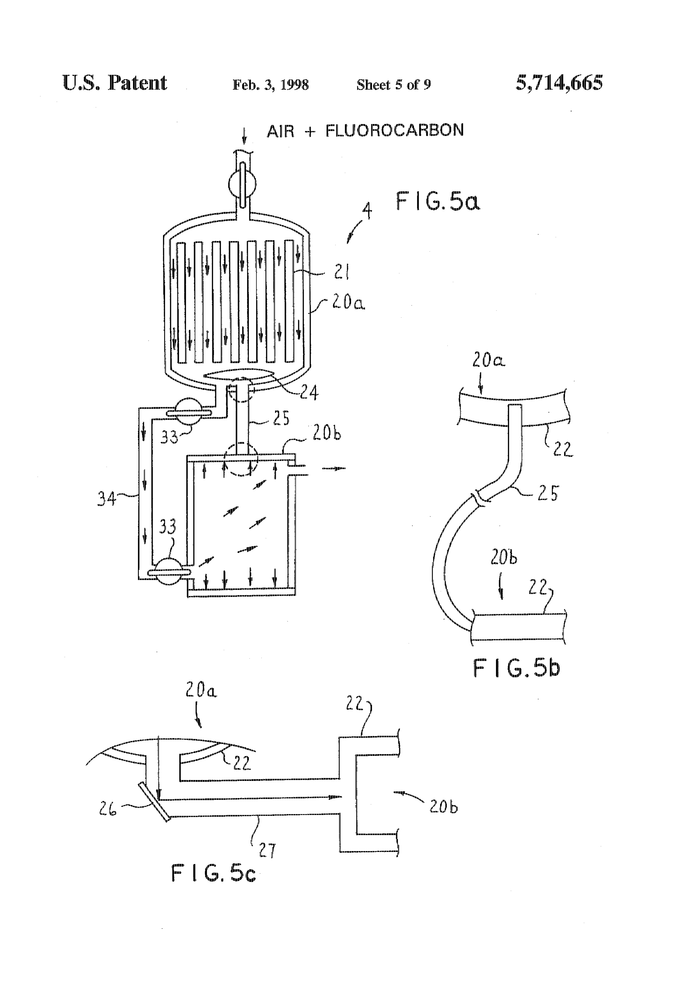
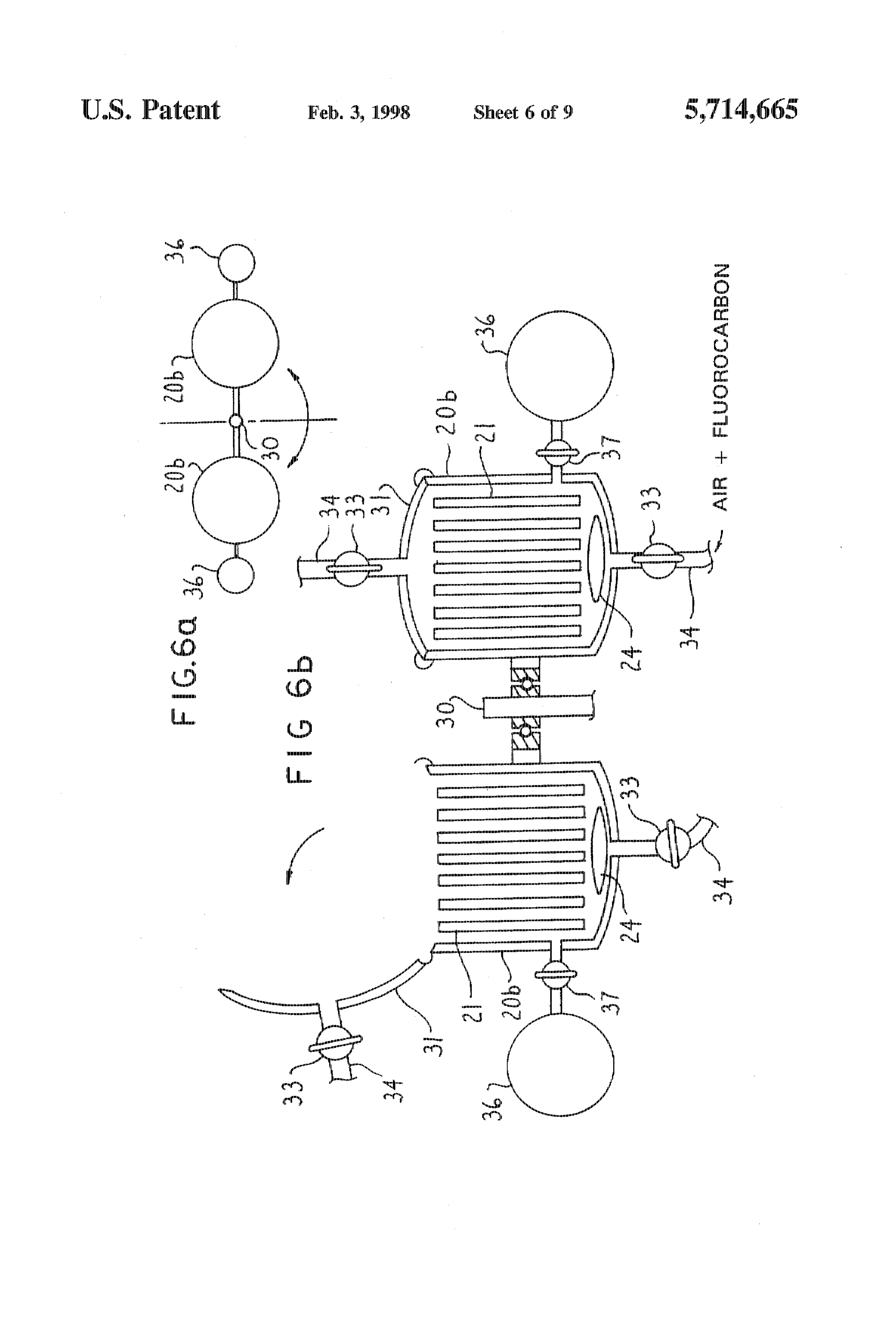
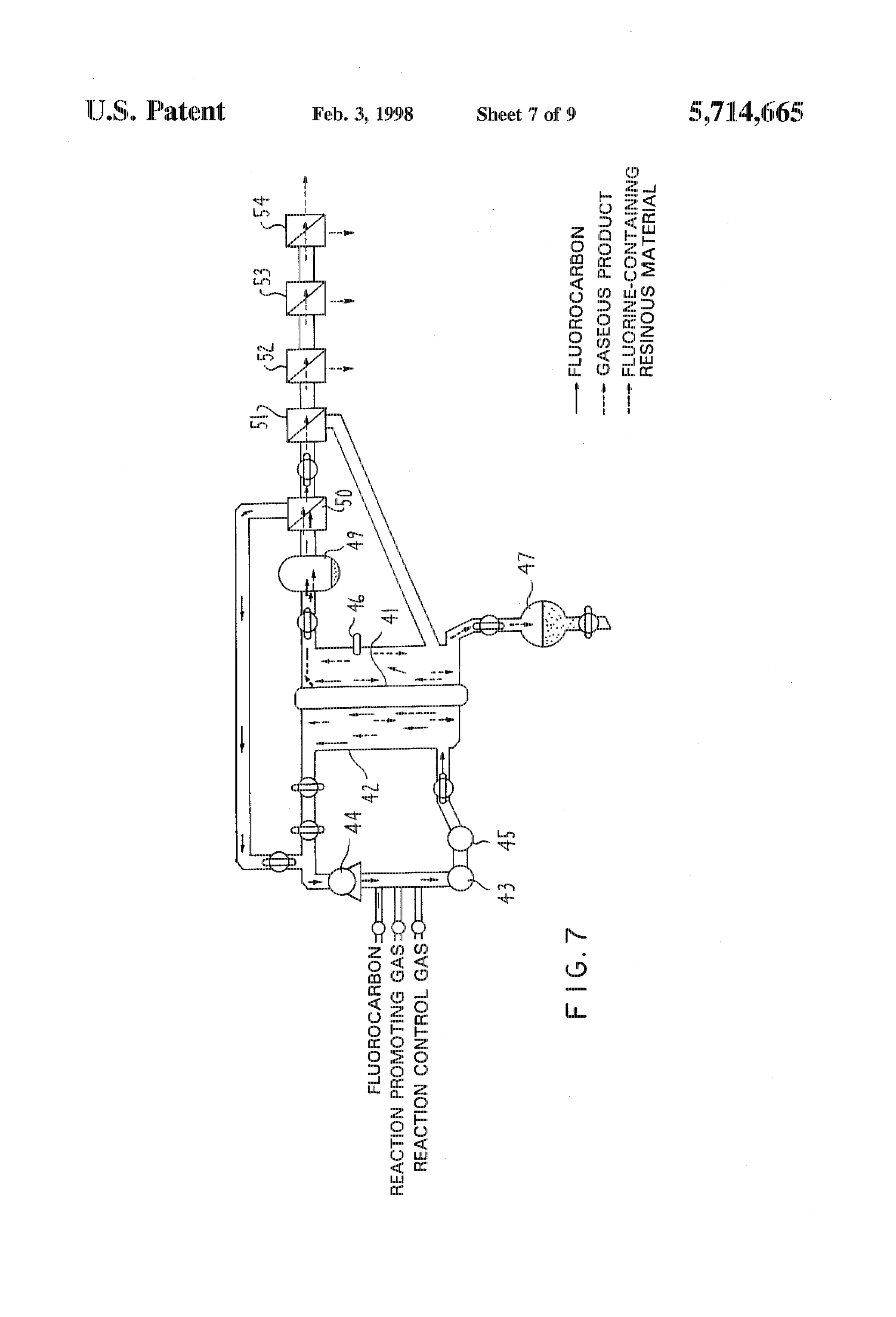
the inner Surface of the reactor; When moisture is present in a photolyric reactor, there is FIG. 5a is a photolytic reactor having a light source unit the high possibility that hydrogen fluoride, which is harmful and a reactor Limit which are separated from each other, FIG. 25 to human body, will be produced during the course of the 5b is a schematic view showing an optical fiber connector photolyric reaction. Accordingly, it is essential to introduce. between the light source unit and the reactor unit, and FIG. into the reactor, a fluorocarbon and air from which moisture Sc is a schematic view showing another type of connector has been completely removed. Chlorine (as will be gener using a high reflection mirror; ated from ozone layer-depleting substances, 1,1,1- FIGS. 6a and 6b are, respectively, a top view and a side 30 trichloroethane and the like) or bromine (as will be gener view, partially in section, of a photolytic reactor according ated from specific halons) can be readily removed by a gas to a further embodin lent of the invention; separator such as a gas separation membrane. The thus FIG. 7 is a schematic view showing a CFC decomposition removed gas is collected and stored in a storing unit. On the reactor used in an example of the invention; other hand, the fluorine-containing powder which is pro FIG. 8(a) to 8(c) are, respectively, graphs showing the 35 duced through the photolyric reaction is solid in nature and absorption spectra of gases separated during a continuous can be separated in the photolytic reactor and collected in a decomposition and separation test of CFC 12 using a sili collector unit.
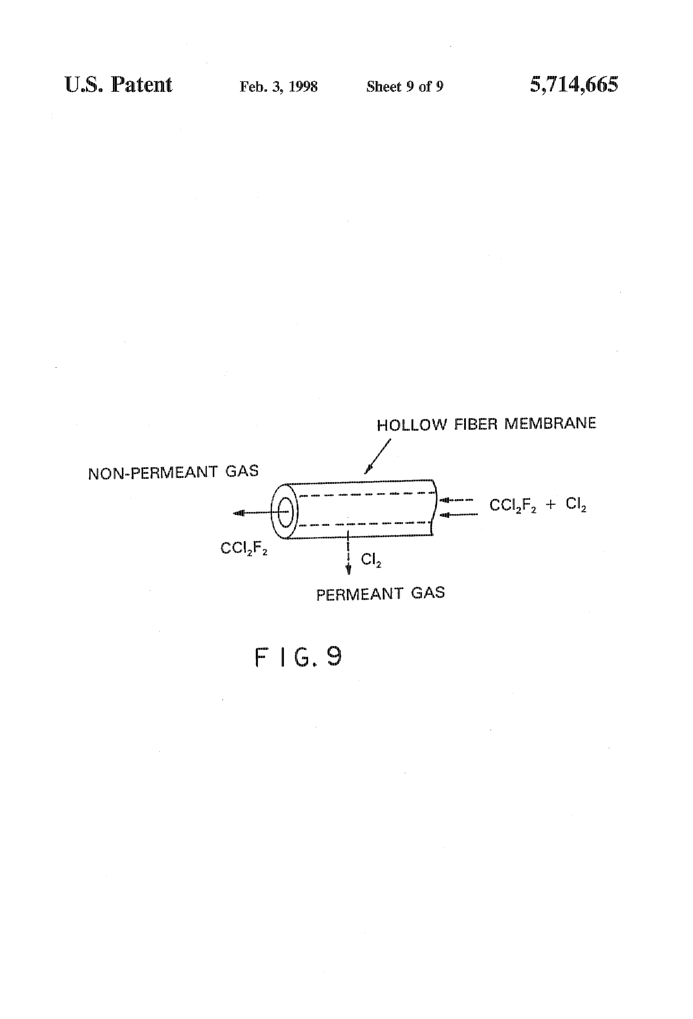
cone hollow fiber membrane and a polyimide hollow fiber The principle of the method according to the invention is membrane under different reaction conditions; and based on the photodissociation reaction of halogen atoms. FG. 9 is a schematic view showing the separation 40 such as of ozone layer-depleting substances caused by UW between CF 12 and Clby use of a hollow fiber membrane. light occurring in the ozone layer. This photodissociation reaction is efficiently conducted in a reactor on the ground
PREFERRED EMBOE)IMEN 'S OF THE in the practice of the invention. Thus, the ozone layer INVENTION depleting substances can be rendered harmless according to 45 the method of the invention.
In our Japanese Patent Applications set out hereinbefore, Analyses and Prediction of Decomposition Reactions of we proposed an optimum wavelength for decomposition of Ozone layer-depleting substances. With UW CFCs which is in the vicinity of 190 nm. We have now found Light According to a Molecular Orbital Method that the low pressure mercury lamp used for the decompo sition was not able to output a wavelength higher than 185 50 In Our previous Japanese patent application, the decorn nnn. Accordingly, there seems to be the high possibility that position reaction of CFC through UV light was analyzed by the wavelength at which the ozone layer-depleting Sub calculation according to the molecular orbital method (PM3) stances can be most efficiently decomposed is not higher using a personal computer, with the following predictions. than 185 nm rather than not higher than 190 nm. i) It was found that when five CFC compoucids and CFC For example, the decomposition of optimum wavelength radicals were calculated with respect to the bonding of the CFC12 becomes 169 nm when calculating (3.21G) strengths of C-Cl, C-F and C-C bonds, the bond the CFC12 using a non-experimental molecular orbital ing energy was about 10 eV for the C-C bond, about (nethod (Gaussian 92, Gaussian, Inc.) capable of directly 14.5 eV for the C-F bond and about 12 eV for the calculating the optimum wavelength for the photodissocia C-C bond irrespective of the types of five CFC tion of CFCs 60 compounds and CFC radicals (chlorine-dissociated The CFCs (CFCs) which are used for decomposition in radicals). If a limited wavelength of UV light would be the practice of the invention include, for example, CFC11 used, it would be highly possible that the C-Cl bond (CCF), CFC12 (CCIF), CFC113 (CCIF-CCIF), alone which has the smallest bonding energy could be CFC114 (CCIF-CCIF). CFC115 (CCIF-CF) and the like. photodissociated (see Table 1). The fluorocarbon analogues used in the invention include 65 (ii) In view of the potential curves of the photolytic halons (1211: CFCLBr, 1301: CFBr, 2402: CFBrCFBr), decomposition (for Cl dissociation) of the five CFC HCFCs (22: CHFC), 123: CHCICF; 141b: CHCClF), compounds and the CFC radicals, the potentials of CFC
Page 13
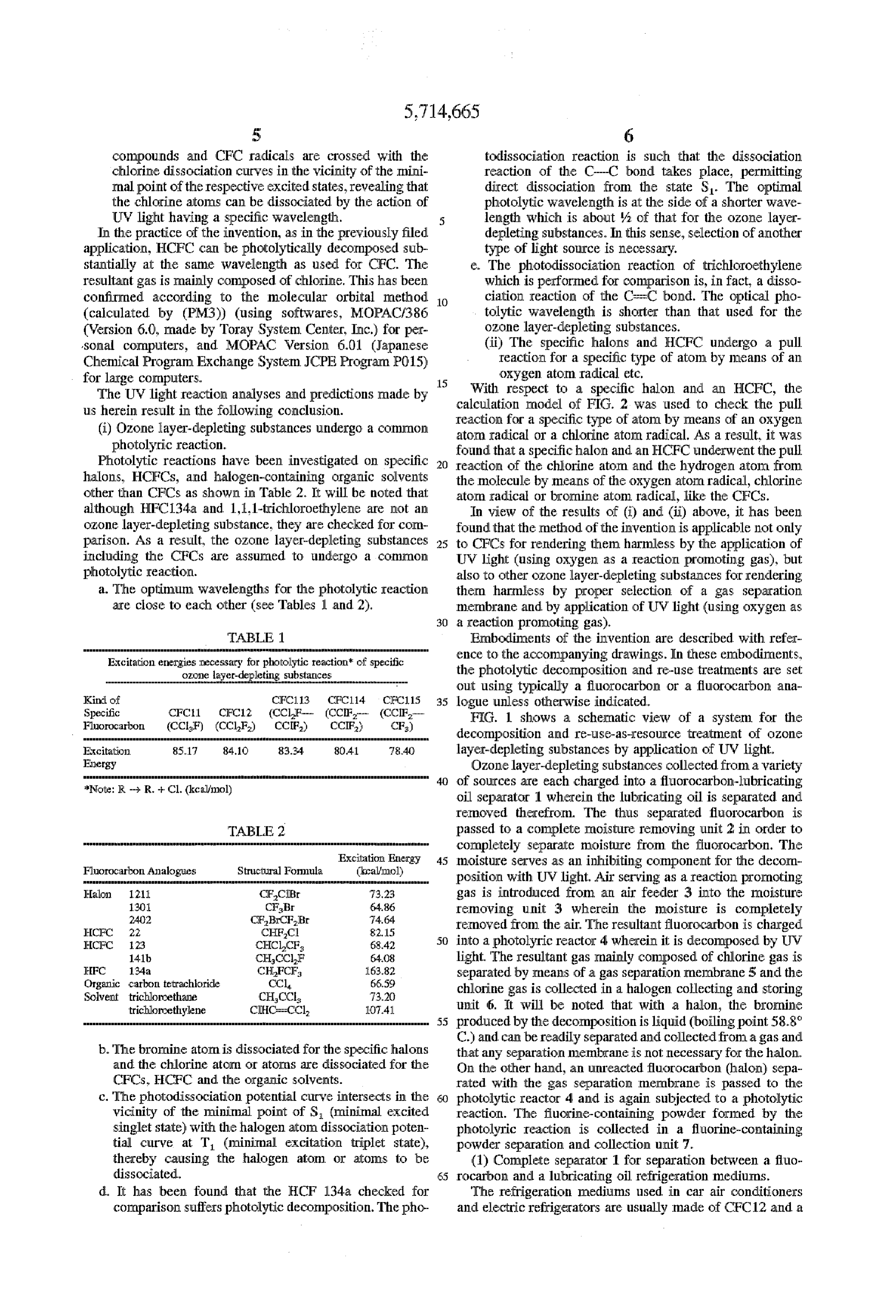
compounds and CFC radicals are crossed with the to dissociation reaction is such that the dissociation chlorine dissociation curves in the vicinity of the mini reaction of the C-C bond takes place, permitting Imal point of the respective eXcited states, revealing that direct dissociation from the state S. The optimal the chlorine atoms can be dissociated by the action of photolytic wavelength is at the side of a shorter wave UV light having a specific wavelength. length which is about/ of that for the ozone layer In the practice of the invention, as in the previously filed depleting substances. In this sense, Selection of another application, HCFC can be photolytically decomposed sub type of light source is necessary. stantially at the same wavelength as used for CFC. The The photodissociation reaction of trichloroethylene resultant gas is mainly composed of chlorine. This has been which is performed for comparison is, in fact, a disso confirmed according to the molecular orbital method O ciation reaction of the CircC bond. The optical pho (calculated by (PM3)) (using softwares, MOPAC/386 tolytic wavelength is shorter than that used for the (Version 6.0, made by Toray System. Center, Inc.) for per ozone layer-depleting substances. sonal computers, and MOPAC Version 6.01 (Japanese (ii) The specific halons and HCFC undergo a pull Chemical Program. Exchange System. JCPE Program PO15) reaction for a specific type of atom by means of an for large computers. 15
Oxygen atom radical etc.
The UV light reaction analyses and predictions made by With respect to a specific halon and an HCFC, the us herein result in the following conclusion. calculation model of FIG. 2 was used to check the pull (i) Ozone layer-depleting substances undergo a common reaction atom for a specific type of atom by means of an oxygen radical or a chlorine atoir radical. As a result, it was photolytic reaction. found that a specific halon and an HCFC underwent the pull Photolytic reactions have been investigated on specific 20 reaction of the chlorine atom and the hydrogen aton from halons, HCFCs, and halogen-containing Organic solvents the molecule by means of the oxygen atom radical, chlorine other than CFCs as shown in Table 2. It will be noted that aton radical or bromine atom. radical, like the CFCs. although HFC134a and 1,1,1-trichloroethylene are not an In view of the results of (i) and (ii) above, it has been CZone layer-depleting substance, they are checked for corn found that the method of the invention is applicable not only parison. As a result, the OZOne layer-depleting Substances 25 to CFCs for rendering them harmless by the application of including the CFCs are assumed to undergo a common UV light (using Oxygen as a reaction promoting gas), but photolytic reaction also to other czone layer-depleting substances for rendering a. The optimum wavelengths for the photolytic reaction thern harmless by proper selection of a gas separation are close to each other (see Tables 1 and 24), membrane and by application of UV light (using oxygen as 30 a reaction promoting gas).
Embodiments of the invention are described with refer reaction cf specific ence to the accompanying drawings. In these embodiments, the photolytic decompo El and re-use treatments are Set out using typically a fluorocarbon or a fluorocarbon ana
Kird of CFC113. FC114 CFC115 35 logue unless otherwise indicated. Specific CFC11 CFC12 (CCLF. (CCIF F.G. 1 shows a scheinatic view of a system for the Fluorocarbon (CC. 8 CF decomposition and re-use-as-resource treatment of ozone
Excitation. 85.17 84.1C 83.34. 80.41 8.4 layer-depleting substances by application of UV light, E Ozone layer-depleting Substances collected from a variety O of sources are each charged into a fluorocarbon-lubricating oil separator 1 wherein the lubricating oil is separated and removed therefrom. The thus separated fluorocarbon is passed to a complete moisture removing unit 2 in order to completely separate moisture from the fluorocarbon. The
Excitation Energ 45 moisture serves as an inhibiting component for the decorn
Fluorocarbon Analogues Structural Formula (kcalool position with UV light, Air Serving as a reaction promoting Hatlon 1211. CF. 3. gas is introduced from an air feeder 3 into the moisture
CFBr
CFBrCFEr
removing unit 3 wherein the moisture is completely
HCF F.Cl Ex retnoyed from the air. The resultant fluorocarbon is charged ECF 12: CHCCF 842 50 into a photolyric reactor 4 wherein it is decomposed by UW 141b CHCClF 6,408 light. The resultant gas mainly composed of chlorine gas is HFC 134a CHFCF 63.82 separated by Irneans of a gas separation membrane 5 and the Organic carbon tetrauchloride wa, 66.59 chlorine gas is collected in a halogen collecticig and storing Solvent trichloroethane Cls 3.20 trichloroethylene CCl O41 unit 6. It will be noted that with a halon, the bronine 55 produced by the decomposition is liquid (boiling point 58.8
C.) and can be readily separated and collected from a gas and b. The bronchine atorn is dissociated for the specific halorusthat any separation membrane is not necessary for the halon. and the chlorine atorn Orators are dissociated for the On the other hand, an unreacted fluorocarbon (halon) sepa CFCs, HCFC and the organic solvents rated with the gas separation membrane is passed to the c. The photodissociation potential curve intersects in the 50 photolytic reactor 4 and is again subjected to a photolytic vicinity of the minimal point of S (minimal excited reaction. The fluorine-containing powder formed by the Singlet state) with the halogen aton dissociatic poten photolyric reaction is collected in a fluorine-containing tial curve at T (minimal excitation triplet state). powder separation and C In lit 7. thereby causing the halogen atom or atoms to be (1) Complete separator 1 for separation between a fluo dissociated. 55 rocartoon and a lubricating oil refrigeration mediurns d. It has been found that the HCF 134a checked for The refrigeration mediums used in car air con OS comparison Suffers photolytic decomposition. The pho and electric refrigerators are usually made of CFC 12 and a
Page 14
lubricating oil at a ratio by weight of about 1:1. The separation units 10 have, at an inlet thereof, a duct for lubricating oil is composed of a mineral lubricant containing introducing a refrigeration medium of car air conditioners or an aromatic hydrocarbon. electric refrigerators collected by, for example, a fluorocar (Reaction analyses and predictions for lubricating oils bon collector. The mixture of a fluorocarbon with a Small using a colecular orbital method) 5 amount of a lubricating oil mist is introduced from the duct The lubricating oils in compressors of electric refrigera 11 wherein the CFC 12 and the lubricating oil are separated tors and car air conditioners are made of naphthenes, par from each other into each separation unit 10 operating under affins and aro natic compounds. Prior to experimental tests, normal temperature and normal pressure conditions. The the photolyric characteristics of individual components of thus separated fluorocarbon is passed from an outlet of the naphthenic, parafficic and aromatic lubricating oils are O separation unit 10 to an inlet of a next-stage separation unit determined by calculation according to the molecular orbital 10 through a duct 11. The separation unit 10 has a felt-like method (PM3) using the aforeindicated large computer and filter 12 in the vicinity of its outlet, as shown, in order not a personal computer, with the following results. to permit the mist of the lubricating oil to be entrained along a) The photoexcitation energy of the naphthenic and with the fluorocarbon from the outlet thereof. On the other parafiinic lubricating oils (dissociation of the C-H hand, the separated liquid lubricating oil is collected in a bond) should have an energy which is not less than two lubricating oil storicg unit 13 provided at the bottorn of the times that at a wavelength of 185 nm which is the separation unit 10. In order to permit complete separation shortest wavelength of UV light from a low pressure between the fluorocarbon and the lubricating oil, a baffle mercury lamp (i.e. UV light having a wavelength as plate 15 may be provided at a position in face-to-face short as not larger thany of the wavelength of 185 nm). relation with the direction of blowing the mixture of the Accordingly, the photodissociation does not take place fluorocarbon and the lubricating oil from the inlet toward the on irradiation with the low pressure mercury lamp. inside of the separation unit 10. By this, the stream of the b) On irradiation of aromatic lubricating oils with a low mixture introduced into the separation unit 10 is blown pressure mercury lamp at 185 nm, the C-H bond may against the baffle plate 15 to prevent the lubricating oil from Scattering. In this manner, the passage of the mixture of the be photodissociated. When the aromatic radicals and , fluorocarbon the chlorine radicals produced by photodissociation of and lubricating oil through the multi-stage CFCs are joined to each other, there is the likelihood separation units 10 enables one to completely separate the that toxic compounds are produced. To avoid this, the fluorocarbon from the lubricating oil.
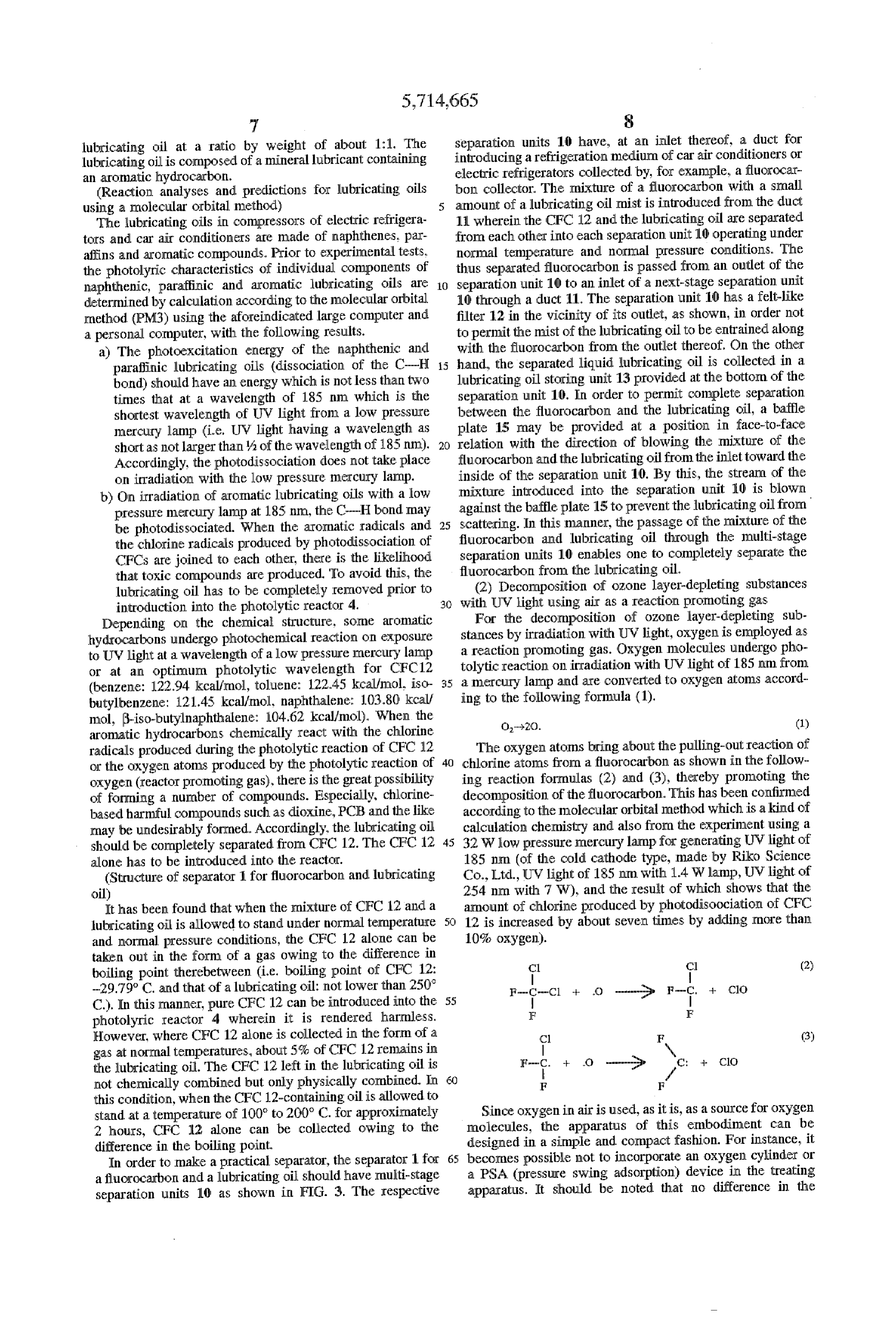
lubricating oil has to be completely renoved prior to (2) Decomposition of ozone layer-depleting substances introduction into the photolytic reactor 4. 30 with UV light using air as a reaction promoting gas Depending on the chemical structure, sorne aromatic For the decomposition of ozone layer-depleting sub hydrocarbons Undergo photochemical reaction on exposure stances by irradiation with UV light, oxygen is employed as to UV light at a wavelength of a low pressure mercury lamp a reaction promoting gas. Oxygen molecules undergo pho or at an optimum photolytic wavelength for CFC 12 tolytic reaction on irradiation with UV light of 185 nm from (benzene: 122.94 kcal/mol, toluene: 122.45 kcal/mol iso 35 a mercury lamp and are converted to oxygen atoms accord butylbenzene: 121.45 kcal/mol, naphthalene: 103.80 kcal/ ing to the following formula (1).
mol, 3-iso-butylnaphthalene: 104.62 kcal/mol). When the O-20. (1) aromatic hydrocarbons chemically react with the chlorine radicals produced during the photolytic reaction of CFC 12 The oxygen atoms bring about the pulling-out reaction of or the oxygen atoms produced by the photolytic reaction of chlorine atoms from a fluorocarbon as shown in the follow Xyger (reactor promoting gas), there is the great possibility ing reaction formulas (2) and (3), thereby promoting the of for Ining a number of compounds. Especially, chlorine decomposition of the fluorocarbon. This has been confirmed based harmful compounds such as dioxine, PCB and the like according to the molecular orbital method which is a kind of may be undesirably formed. Accordingly, the lubricating oil calculation chemistry and also from the experiment using a should be completely separated from CFC 12. The CFC 12 45 32 Wlow pressure mercury lamp for generating UV light of alone has to be introduced into the reactor. 185 nm (of the cold cathode type, made by Riko Science (Structure of separator for fluorocarbon and lubricating Co., Ltd., UV light of 185 nm with 1.4 W lamp, UV light of oil) 254 nm with 7 W), and the result of which shows that the It has been found that when the mixture of CFC 12 and a amount of chlorine produced by photodisoociation of CFC lubricating oil is allowed to stand under normal temperature 12 is increased by about sever times by adding more than and normal pressure conditions, the CFC 12 alone can be 10% oxygen).
taken out in the form of a gas owing to the difference in Cl Cl (2) boiling point therebetween (i.e. boiling point of CFC 12: ...A.
-29.79° C. and that of a lubricating oil: not lower than 250° F--Cl + O - G F- -- ClO C.). In this manner, pure CFC 12 can be introduced into the 55 F F photolyric reactor 4 wherein it is rendered harmless.
However, where CFC 12 alone is collected in the form of a Cl F (3) gas at normal ten cratures about 5% of CFC 12 remains in \ the lubricating oil. The CFC 12 left in the lubricating oil is F- + 0 - G C: + CO not chemically combined but only physically combined. In 60 F F this condition, when the CFC 12-containing oil is allowed to stand at a temperature of 100° to 200° C. for approximately Since oxygen in air is used, as it is, as a source for oxygen 2 hours, CFC 12 alone can be collected owing to the molecules, the apparatus of this embodiment can be difference in the boiling point. designed in a simple and compact fashion. For instance, it In order to make a practical separator, the separator for 65 becomes possible not to incorporate an oxygen cylinder or a fluorocarbor and a lubricating oil should have multi-stage a PSA (pressure swing adsorption) device in the treating separation units 10 as shown in FIG. 3. The respective apparatus. It should be noted that no difference in the
Page 15
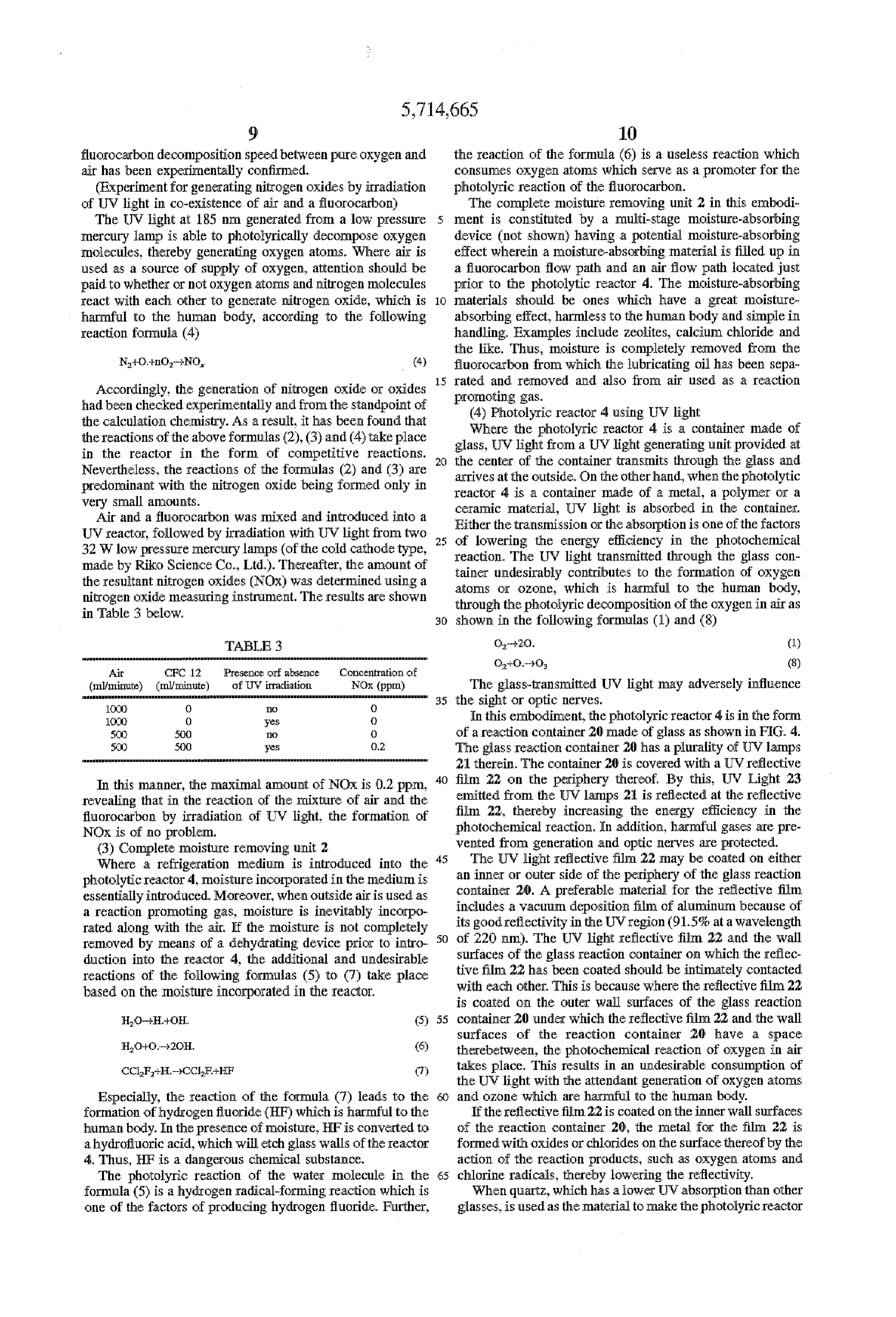
fluorocarbon decomposition speed between pure oxygen and the reaction of the formula (6) is a useless reaction which air has been experimentally confirmed. consumes oxyger atoms which serve as a promoter for the (Experiment for generating nitrogen oxides by irradiation photolyric reaction of the fluorocarbon. of UV light in co-existence of air and a fluorocarbon) The complete moisture removing unit 2 in this embodi. The UV light at 185 nm generated from a low pressure ment is constituted by a multi-stage moisture-absorbing mercury lamp is able to photolyrically decompose oxygen device (not shown) having a potential moisture-absorbing molecules, thereby generating oxygen atoms. Where air is effect wherein a moisture-absorbing material is filled up in used as a source of supply of oxygen, attention should be a fluorocarbon flow path and an air flow path located just paid to whether or not oxygenatorms and nitrogen molecules prior to the photolytic reactor 4. The moisture-absorbing react with each other to generate nitrogen oxide, which is 1O materials should be ones which have a great moisture harmful to the human body, according to the following absorbing effect, harmless to the human body and simple in reaction formula (4) handling. Examples include zeolites, calcium chloride and the like. Thus, moisture is completely removed from the
N+C+nd-NO, (4) fluorocarbon from which the lubricating oil has been sepa 15 cated and removed and also from air used as a reaction
Accordingly, the generation of nitrogen oxide or oxides promoting gas.
had been ch cked experimentally and from the standpoint of (4) Photolyric reactor 4 using UV light the calculation chemistry. As a result, it has been found that Where the photolyric reactor 4 is a container made of the reactions of the above formulas (2), (3) and (4) take place glass, UV light from a UV light generating unit provided at in the reactor in the form of competitive reactions. the center of the container transmits through the glass and Nevertheless, the reactions of the formulas (2) and (3) are arrives at the outside. On the other hand, when the photolytic predominant with the nitrogen oxide being formed only in reactor 4 is a container made of a metal, a polymer or a very Small amounts. ceramic material, UV light is absorbed in the container. Air and a fluorocarbon was mixed and introduced into a
UV reactor, followed by irradiation with UV light from two Either the transmission or the absorption is one of the factors 32W low pressure mercury lamps (of the cold cathode type, reaction. The the f lowering energy efficiency in the photochemical made by Riko Science Co., Ltd.). Thereafter, the amount of tainer undesirably light
UV transmitted through the glass con contributes to the formation of oxygen the resultant nitrogen oxides (NOx) was determined using a atoms or ozone, which is harmful to the human body, nitrogen oxide measuring irstrument. The results are shown through the photolyric decomposition of the oxygen in air as in Table 3 below, 3C) shown in the following formulas (1) and (8)
Concentraticor of
Air (ml/minut ) NOx (ppm) The glass-transmitted UV light may adversely influence
35 the sight or optic nerves.
OCO O yes O In this embodiment, the photolyric reactor 4 is in the form 500 O O of a reaction container 20 made of glass as shown in FIG. 4. 500 0.2 The glass reaction container 20 has a plurality of UW lamps 21 therein. The container 20 is covered with a UW reflective
In this manner, the maximal amount of NOx is 0.2 ppm, film 22 on the periphery thereof. By this, UV Light 23
revealing that in the reaction of the mixture of air and the emitted from the UV lamps 21 is reflected at the reflective fluorocarbon by irradiation of UV light, the formation of film 22, thereby increasing the energy efficiency in the NOx is of no problem. photochemical reaction. In addition, harmful gases are pre (3) Complete moisture removing unit 2 vented from generation and optic nerves are protected. Where a r tration medium is introduced into the The UV light reflective film 22 may be coated on either photoly ctor 4. Inoisture incorporated in the medium is an inner or outer side of the periphery of the glass reaction essentially introduced. Moreover, when outside air is used as container 20. A preferable material for the reflective film a reaction promoting gas, moisture is inevitably incorpo includes a vacuum deposition film of aluminum because of rated along with the air. If the moisture is not complete its good reflectivity in the UV region (91.5% at a wavelength removed by means of a dehydrating device prior to intro 50 of 220 nm). The UV light reflective film 22 and the wall duction into the reactor 4, the additional and undesirable surfaces of the glass reaction container on which the reflec reactions of the following formulas (5) to (7) take place tive with film 22 has been coated should be intimately contacted each other. This is because where the reflective film 22 based on the Inoisture incorporated in the reactor.
is coated on the outer wall surfaces of the glass reaction (5) : container 20 under which the reflective film 22 and the wall surfaces of the reaction container 20 have a space
therebetween, the photochemical reaction of oxygen in air
CCF-H...-9CC takes place. This results in an undesirable consumption of
the UV light with the attendant generation of oxygen atoms
Especially, the reaction of the formula (7) leads to the 50 and ozone which are harmful to the human body. formation of hydrogen fluoride (HF) which is harrnful to the If the reflective firm. 22 is coated on the inner Wall surfaces human body. In the presence of moisture, HFis converted to of the reaction container 20, the metal for the film 22 is a hydrofluoric acid, which will etch glass walls of the reactor formed with oxides or chlorides on the surface thereof by the 4. Thus, HF is a dangerous chemical substance. action of the reaction products, such as oxygen atoms and The photolyric reaction of the water molecule in the 65. chlorine radicals, thereby lowering the reflectivity. formula (5) is a hydrogen radical-forming reaction which is When quartz, which has a lower UW absorption than other one of the factors of producing hydrogen fluoride. Further, glasses, is used as the material to make the photolyric reactor
Page 16
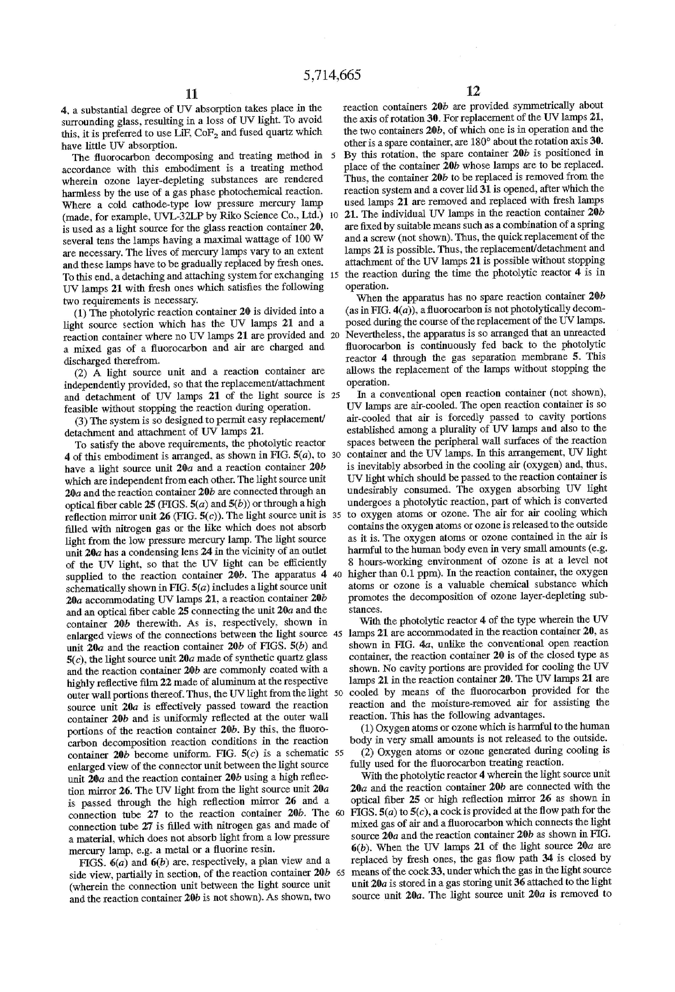
4, a substantial degree of UW absorption takes place in the reaction containers 2.0E are provided symmetrically about surrounding glass, resulting in a loss of UV light. To avoid the axis of rotation 30. For replacement of the UV lamps 21, this, it is preferred to use LiF CoE and fused quartz which the two containers 20b, of which one is in operation and the have little UW absorption. other is a spare contairer, are 180° about the rotation axis 30. The fluorocarbon decomposing and treating method in 5 By this rotation, the spare container 20b is positioned in accordance with this enbodiment is a treating method place of the container 20b whose lamps are to be replaced. wherein ozone layer-depleting substances are rendered Thus, the container 20b to be replaced is removed from the harmless by the use of a gas phase photochemical reaction. reaction system and a cover lid 31 is opened, after which the Where a cold cathode-type low pressure mercury lamp used lamps 21 are removed and replaced with fresh lamps (made, for example, UWL-32LP by Riko Science Ltd.) 10 21. The individual UV lamps in the reaction container 20b is used as a light source for the glass reaction container 20, are fixed by suitable means such as a combination of a spring several tens the lamps having a maximal wattage of 100 W and a screw (not shown). Thus, the quick replacement of the are necessary. The lives of mercury lamps vary to an extent lamps 21 is possible. Thus, the replacement/detachment and and these lamps have to be gradually replaced by fresh ones. attachment of the UV lamps 21 is possible without stopping To this end, a detaching and attaching system for exchanging the reaction during the time the photolytic reactor 4 is in UV lamps 21 with fresh ones which satisfies the following operation.
two requirements is necessary. When the apparatus has no spare reaction container 20b (1) The photolyric reaction container 20 is divided into a (as in FIG. 4(a)), a fluorocarbon is not photolytically decom light source section which has the UV lamps 21 and a posed during the course of the replacement of the UW lamps. reaction container where no UV lamps 21 are provided and 2 Nevertheless, the apparatus is so arranged that an unreacted a mixed gas of a fluorocarbon and air are charged and fluorocarbon is continuously fed back to the photolytic discharged therefrom. reactor 4 through the gas separation membrane 5. This (2) A light source unit and a reaction container are allows the replacement of the lamps without stopping the independently provided, so that the replacement/attachment operation.
and detachment of UV lamps 21 of the light source is 25 In a conventional open reaction container (not shown). feasible without stopping the reaction during operation. UW lamps are air-cooled. The open reaction container is so (3) The system is so designed to permit easy replacement? air-cooled that air is forcedly passed to cavity portions detachment and attachment of UV lamps 21. established among a plurality of UV lamps and also to the To satisfy the above requirements, the photolytic reactor spaces between the peripheral wall Surfaces of the reaction 4 of this embodiment is arranged, as shown in FIG. 5(a), to 30 container and the UW lamps. In this arrangement, UV light have a light source unit 20a and a reaction container 20b is inevitably absorbed in the cooling air (Oxygen) and, thus, which are independent from each other. The light source unit UV light which should be passed to the reaction container is 20a and the reaction container 20b are connected through an undesirably consumed. The oxygen absorbing UV light optical fiber cable 25 (FIGS. 5(a) and5(b)) or through a high undergoes a photolytic reaction, part of which is converted reflection mirror unit 26 (FIG. 5(c)). The light source unit is to oxygen atoms or ozone. The air for air cooling which filled with nitrogen gas or the like which does not absorb contains the oxygen atoms or OZone is released to the outside light from the low pressure mercury lamp. The light source as it is. The oxygen atoms or ozone contained in the air is unit 20a has a condensing lens 24 in the vicinity of an outlet harmful to the human body even in very small amounts (e.g. of the UV light, so that the UV light can be efficiently 8 hours-working environment of ozone is at a level not supplied to the reaction container 20b. The apparatus 4 higher than 0.1 ppm). In the reaction container, the oxygen schematically shown in FIG. 5(a) includes a light source unit atoms or ozone is a valuable chemical Substance which 20a accommodating UV lamps 21, a reaction container 20b promotes the decomposition of ozone layer-depleting sub and an optical fiber cable 25 connecting the unit 20a and the Stance.S.
container 20b therewith. As is, respectively, shown in With the photolytic reactor 4 of the type wherein the UV enlarged views of the connections between the light source lamps 21 are accommodated in the reaction container 20, as unit 20a and the reaction container 20b of FIGS. 5(b) and shown in FIG. 4a, unlike the conventional open reaction 5(c), the light source unit 20a made of synthetic quartz glass container, the reaction container 20 is of the closed type as and the reaction container 20b are commonly coated with a shown. No cavity portions are provided for cooling the UW highly reflective film 22 made of aluminum at the respective lamps 21 in the reaction container 20. The UW lamps 21 are outer wallportions thereof. Thus, the UV light from the light cooled by means of the fluorocarbon provided for the source unit 20a is effectively passed toward the reaction reaction and the moisture-removed air for assisting the container 20b and is uniformly reflected at the outer wall reaction. This has the following advantages. portions of the reaction container 20h. By this, the fluoro (1) Oxygen atoms or ozone which is harmful to the human carbon decomposition reaction conditions in the reaction body in very small amounts is not released to the outside. container 20b become uniform. FIG. 5(c) is a schematic (2) Oxygen attorns or OZone generated during cooling is enlarged view of the connector unit between the light source fully used for the fluorocarbon treating reaction. unit 20a and the reaction container 20h using a high reflec With the photolytic reactor 4 wherein the light source unit tion mirror 26. The UV light from the light source unit 20a 20a and the reaction container 20b are connected with the is passed through the high reflection mirror 26 and a optical fiber 25 or high reflection mirror 26 as shown in connection tube 27 to the reaction container 20b. The 60 FIGS. 5(a) to 5(c), a cock is provided at the flow path for the connection tube 27 is filled with nitrogen gas and made of mixed gas of air and a fluorocarbon which connects the light a material, which does not absorb light from a low pressure source 20a and the reaction container 20b as shown in FIG. mercury lamp, e.g. a metal or a fluorine resin. 6(b). When the UV lamps 21 of the light source 20a are FIGS. 6(a) and 6(b) are, respectively, a plan view and a replaced by fresh ones, the gas flow path 34 is closed by side view, partially in section, of the reaction container 20b 5 means of the cock3.3, under which the gas in the light source (wherein the connection unit between the light source unit unit 20a is stored in a gas storing unit 36 attached to the light and the reaction container 20b is not shown). As shown, two source unit 20a. The light source unit 2.0a is removed to
Page 17
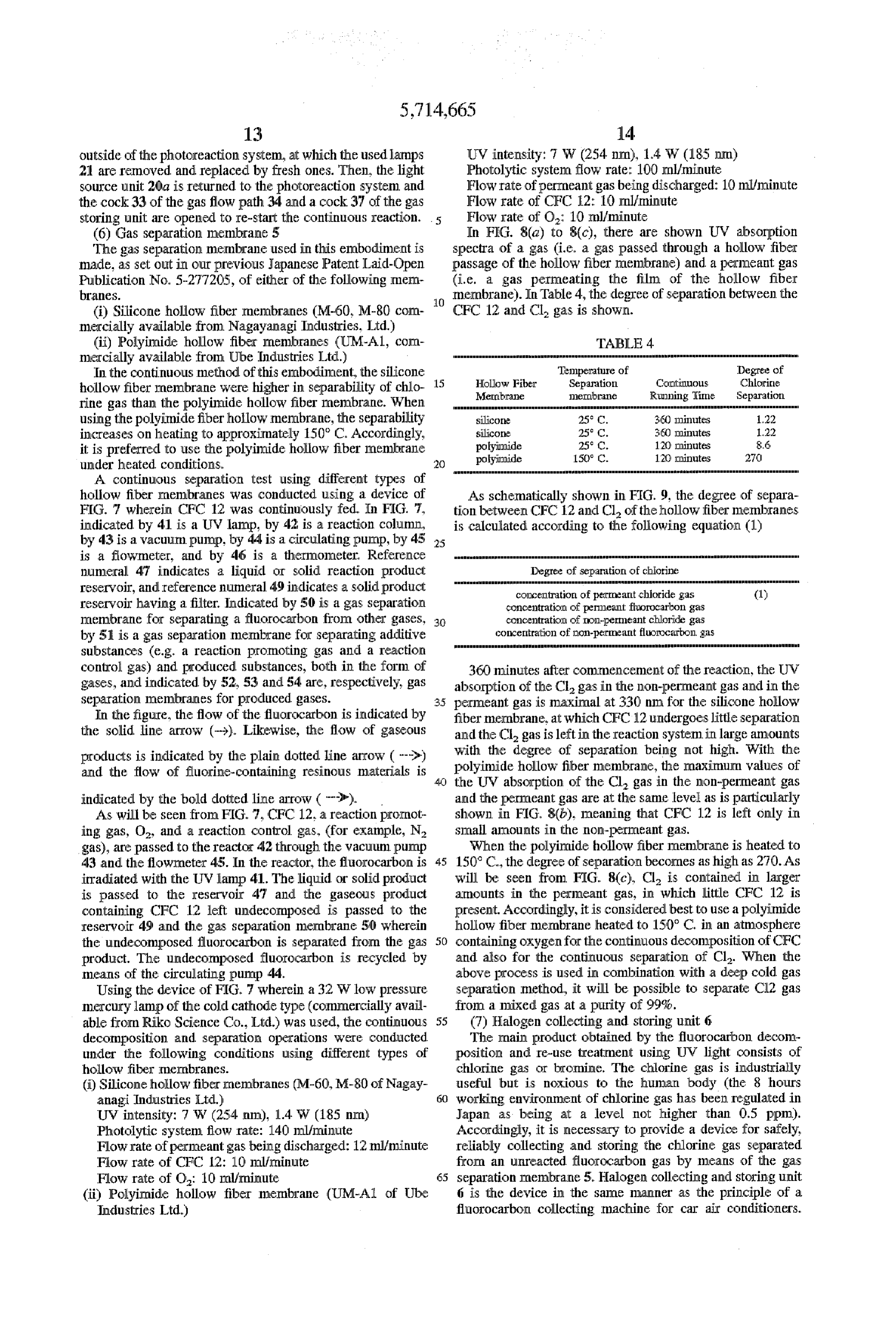
outside of the photoireaction system, at which the used lamps UV intensity: 7 W (254 nm), 1.4W (185 nm) 21 are removed and replaced by fresh ones. Then, the light Photolytic system flow rate: 100 ml/minute Source unit 20a is returned to the photoreaction system and Flow rate of perimeant gas being discharged: 10 ml/minute the cock 33 of the gas flow path 34 and a cock 37 of the gas Flow rate of CFC 12: 10 ml/minute storing unit are opened to re-start the continuous reaction. .. ) Flow rate of O: 10 ml/minute (6) Gas separation membrane 5 In FIG. 8(a) to 8(c), there are shown UW absorption The gas separation membrane used in this embodiment is spectra of a gas (i.e. a gas passed through a hollow fiber made, as set out in our previous Japanese Patent Laid-Open passage of the hollow fiber membrane) and a perimeant gas Publication No. 5-277205, of either of the following men (i.e. a gas permeating the film of the hollow fiber branes. 10 membrane). In Table 4, the degree of separation between the (i) Silicone hollow fiber membranes (M-60, M-80 com C 12 and Cl gas is shown.
mercially available from Nagayanagi Industries. Ltd.)
(ii) Polyimide hollow fiber membranes (UM-A1, corn TABLE 4 mercially available from Ube Industries Ltd.)
In the continuous method of this embodiment, the silicone Temperature of Degree of hollow fiber membrane were higher in Separability of chlo 15 Hollow Fiber Separation Continuous Chlorine ertbrae Running line Separation rine gas than the polyimide hollow fiber membrane. When using the polyimide fiber hollow membrane, the separability silicone 360 minutes increases on heating to approximately 150° C. Accordingly, silicone polyimide
360 dinutes 120 poinutes it is preferred to use the polyimide hollow fiber membrane polyimide 150° C. 120 minutes under heated conditions. 20
A continuous separation test using different types of hollow fiber membranes was conducted using a device of As schematically shown in FIG. 9, the degree of separa FIG. 7 wherein CFC 12 was continuously fed. In FIG. 7, tion between CFC 12 and Cl of the hollow fiber membranes indicated by 41 is a UV lamp, by 42 is a reaction column, is calculated according to the following equation (1) by 43 is a vacuum puncp, by 44 is a circulating pump, by 45 25 is a flowmeter, and by 46 is a thermometer, Reference numeral 47 indicates a liquid or solid reaction product Degre of separation of chlorine annu reservoir, and reference numeral 49 indicates a solid product concentration of perimeant chloride gas (1) reservoir having a filter. Indicated by 50 is a gas separation concentration of perimeant fluorocarbon gas membrane for separating a fluorocarbon from other gases, 30 concentration of non-perimeant chloride gas by 51 is a gas separation membrane for separating additive concentration of non-perneant fluorocarton Substances (e.g. a reaction promoting gas and a reaction control gas) and produced substances, both in the form of 360 minutes after commencement of the reaction, the UW gases, and indicated by 52, 53 and 54 are, respectively, gas absorption of the Cl gas in the non-perimeant gas and in the separation membranes for produced gases. 35 perimeant gas is maximal at 330 nm for the silicone hollow In the figure, the flow of the fluorocarbon is indicated by fiber membrane, at which CFC 12 undergoes little separation the solid line arrow (-)). Likewise, the flow of gaseous and the Cl gas is left in the reaction system in large amounts products is indicated by the plain dotted line arrow ( ->) with the degree of separation being not high. With the and the flow of fluorine-containing resinous materials is 40 the polyimide hollow fiber membrane, the maximum values of UW absorption of the Cl gas in the non-permeant gas indicated by the bold dotted line arrow ( ""). and the perimeant gas are at the same level as is particularly As will be seen from FIG. 7. CFC 12. a reaction promot shown in FIG. 8(b), meaning that CFC 12 is left only in ing gas, O, and a reaction control gas, (for example, N. Small amounts in the non-permeant gas. gas), are passed to the reactor 42 through the vacuum pump When the polyimide hollow fiber membrane is heated to 43 and the flow meter 45. In the reactor, the fluorocarbon is 150° C., the degree of separation becomes as high as 270. As irradiated with the UV lamp 4.1. The liquid or solid product will be seen from FIG. 8(c), Cl is contained in larger is passed to the reservoir 47 and the gaseous product amounts in the permeant gas, in which little CFC 12 is containing CFC 12 left undecomposed is passed to the present. Accordingly, it is considered best to use a polyimide reservoir 49 and the gas separation membrane 50 wherein hollow fiber membrane heated to 150° C. in an atmosphere the undecomposed fluorocarbor is separated from the gas 50 containing oxygen for the continuous decomposition of CFC product. The undecomposed fluorocarbon is recycled by and also for the continuous separation of Cl. When the means of the circulating pump 44. above process is used in combination with a deep cold gas Using the device of FIG. 7 wherein a 32 W low pressure separation method, it will be possible to separate Cl2 gas mercury lamp of the cold cathode type (commercially avail from a mixed gas at a purity of 99%.
able from Riko Science Co., Ltd.) was used, the continuous 55 (7) Halogen collecting and storing unit 6 decomposition and separation operations were conducted The main product obtained by the fluorocarbon decom under the following conditions using different types of position and re-use treatment using UV light consists of hollow fiber rnerbranes. chlorine gas or bromine. The chlorine gas is industrially (ii) Silicone hollow fiber membranes (M-60, M-80 of Nagay useful but is noxious to the human body (the 8 hours anagi Industries Ltd.) working environment of chlorine gas has been regulated in UV intensity: 7 W (254 nm), 1.4 W (185 nm) Japan as being at a level not higher than 0.5 ppm). Photolytic system flow rate: 140 ml/minute Accordingly, it is necessary to provide a device for safely, Flow rate of perimeant gas being discharged: 12 ml/minute reliably collecting and storing the chlorine gas separated Flow rate of CFC 2: 10 ICL/jrrinute from an unreacted fluorocarbon gas by means of the gas Flow rate of O. 10 ml/minute 55 separation membrane 5. Halogen collecting and storing unit (ii) Polyimide hollow fiber membrane (UM-A1 of Ube 6 is the device in the same manner as the principle of a Industries Ltd.) fluorocarbor collecting machine for car air conditioners.
Page 18
More particularly, the chlorine gas is compressed by means What is claimed is:
of a compressor to provide a high temperature and high 1. In an apparatus for continuously decomposing a halo pressure gas. The thus compressed halogen gas is allowed to genated organic compound by a photolytic reaction in a cool in a condenser to provide liquid chlorine, followed by reactor in which the halogenated organic compound is collection and storage in a cylinder in the form of a liquid. mixed with air as a photolytic reaction promoter and then In this manner, the reason why the principle of a fluorocar. subjected to UV radiation to decompose the halogenated bon collecting machine for car air conditioners (or, in some organic compound, the improvement characterized in said cases, the collecting machine itself) is applicable is that the apparatus comprising: means for continuously feeding a CFC 12 has a boiling point very close to that of chlorine. refrigeration medium containing a lubricating oil and a (8) Separation and collection device 7 for fluorine 10 halogenated organic compound to a separation unit; a sepa containing powder ration unit for separating the halogenated organic compound The fluorine-containing powder formed by the polymer from the refrigeration medium under standard temperature ization of reaction intermediates is moved within the reactor and pressure conditions, said separation unit comprising two along with a gas fluent. A felt filter and a reservoir for separation members in fluid communication with one fluorine-containing powder dropped from the filter (i.e. the 15 another, each of said separation fluorine-containing powder separator 7) is provided prior to provided therein for separating members having a baffle
the gas separation membrane 5, so that the fluorine the halogenated organic compound from the lubricating oil; a moisture containing powder is separated and collected from the gas receiving air and the separated halogenated organic com separator for fluent. Another reservoir (not shown) for fluorine-containing pound and removing moisture therefrom to form a dried air powder is provided below the reaction container 20, with which the powder is collected. 20 and halogenated organic compound mixture; neans for (9) Decomposition and re-use treatment apparatus for introducing air into said moisture separator; a photolytic ozone layer-depleting substances in foamed materials reactor for conducting a photolytic reaction with the dried The annual amount of foaming CFC arrives at about air and halogenated organic compound mixture and forming 40,000 tons, which corresponds to 25% of the overall a reaction mixture containing a separated halogen armount of in Japan. With respect to the kinds of ozone 25 compound, said photolytic reactor comprising a reaction layer-depleting Substances, CFC11 amounts to about 25,000 chamber having a plurality of UV lamps provided therein tons per year and CFC 12 amounts to about 12,000 tons a and a UV reflective film provided on the outer periphery year (in 1988). The ozone layer-depleting substances present thereof; a separator for separating the halogen compound in the used foamed materials are released in the air when from the reaction mixture; and a halogen collecting and crushed. Alternatively, when such foamed materials are 30 storing unit for receiving the separated halogen compound, allowed to stand as they are or are used for land-fill, the 2. The apparatus of claim 1, wherein said photolytic materials suffer gradual degradation with the attendant reactor is made of a material selected from the group release of the fluorocarbon contained therein. To avoid this, consisting of LiF, CoF2 and fused quartz, the fluorocarbon in the used, foanned materials has to be 3. In an apparatus for continuously decomposing a halc treatmented to render it harmless. Because the used foamed : genated organic compound by a photolytic reaction in a materials are collected one by one in small amounts, it is reactor in which the halogenated organic compound is reasonable to subject the material to treatment at collection mixed with air as a photolytic reaction promoter and then Celtics. Subjected to UV radiation to decompose the halogenated organic compound, the improvernent characterized in said
The fluorocarbon is collected in a receiver by compress apparatus ing foamed materials only by a compression force at tem comprising: means for continuously feeding a peratures close to normal termperatures such as by electro refrigeration III ediurn containing a lubricating oil and a hydraulic devices thereby permitting the fluorocarbon to be halogenated organic compound to a separation unit; a sepa released and then to be collected by a fluorocarbor collector. ration unit for separating the halogenated organic compound The thus collected fluorocarbon is charged into a fluorocar. from the refrigeration medium under standard temperature bon decomposition and re-use apparatus using UV light and and pressure conditions, said separation unit comprising two is thus rendered harmless. The compression of the foamed separation mernbers in fluid communication with one material is advantageous in that the matrix material of the another, each of said separation members having a baffle foamed material can be reduced in volume. provided therein for separating the halogenated organic As stated hereinabove. according to the embodiments of compound from the lubricating oil, a moisture separator for the invention. Small amounts of refrigeration mediums used receiving air and the separated halogenated organic com in and individually Collected from electric refrigerators, car pound and removing moisture therefronto form a dried air air conditioners and domestic air conditions are collected. and halogenated organic compound mixture; means for The ozone layer-depleting substances contained in the col introducing air into said moisture separator; a photolytic lected mediums can be readily photolytically decomposed reactor for conducting a photolytic reaction with the dried into innocuous Substances which are re-usable as kinds of 55 air and halogenated organic compound mixture and forming resources. The systern of this embodiment involves no a reaction mixture containing a separated halogen chemical treatment step and is able to treat ozone layer compound, said photolytic reactor comprising a tight source depleting substances under conditions close to normal tern means, a reaction chamber in which the photolytic reaction perature and normal pressure conditions. Moreover, the takes place and light tranSImitting means connecting said apparatus is a fully-automatic, continuous treating apparatus lightsource means and said reaction charaber, a separator for and is good at working properties. Nevertheless, the appa separating the halogen compound from the reaction mixture; ratus can be provided as being portable and simple in and a haloger collecting and storing unit for receiving the construction separated halogen compound.
Thus, according to the invention, a system of continu 4. The apparatus of claim 3, wherein said light transmit ously decomposing ozone layer-depleting substances for 65 ting means consists of an optical fiber cable. re-reuse of decomposition products as resources can be 5. The apparatus of claim 3, wherein said light transmit established. ting means consists of a connection pipe filled with nitrogen
Page 19
gas and a reflection rairror for reflecting UV light from said pound and removing moisture therefront to form a dried air light source unit toward said reaction chamber. and halogenated organic compound mixture; means for 6. In an apparatus for continuously decomposing a halo introducing air into said moisture separator; a photolytic genated organic compound by a photolytic reaction in a reactor for conducting a photolytic reaction with the dried reactor in which the halogenated organic compound is air and halogenated organic compound mixture and forming mixed with air as a photolytic reaction promoter and then a reaction mixture containing a separated halogen subjected to UW radiation to decompose the halogenated compound, said photolytic reactor comprising a pair of organic compound, the improvement characterized in said reaction chambers, each of said reaction chambers contain apparatus comprising means for continuously feeding a ing UV lamps and being interchangeably rotatable 180 refrigeration mediurn containing a lubricating oil and a 10 degrees about an axis of rotation between a first position at halogenated organic compound to a separation unit; a sepa which the photolytic reaction is conducted in a reaction ration unit for separating the halogenated organic compound chamber and a second position at which a reaction chamber from the refrigeration medium under standard temperature can be serviced, thereby enabling the photolytic reaction to and pressure conditions, said separation unit comprising two be conducted continuously; a separator for separating the separation members in fluid communication with one halogen compound from the reaction mixture; and a haloger
another, each of said separation members having a baffle collecting and storing unit for receiving the separated halo provided therein for separating the halogenated organic gen compound.
compound from the lubricating oil; a moisture separator for receiving air and the separated halogenated organic corn X: ck ck s: ::
Provenance
- Collection
- Cited prior art
- Original PDF
- patentimages.storage.googleapis.com →
- Filed
- 1995-02-23
- Pages
- 19
- Method
- pdftotext (the PDF's own text layer) + pdftoppm 300dpi page scans
- Source
- Google Patents bibliographic record
- Granted
- 1998-02-03
- Inventors
- Kuninobu Ohtake; Takeshi Ohyama; Hisashi Sakai; Xing-zhe Zhao; Shigeru Morikawa; Tokyo Electric Power Co Inc
- Transcribed from
- patentimages.storage.googleapis.com →