patent · US3188478
Pinhole detector optical system
8 June 1965
Page 1
Drawing sheet — no readable text.
Page 2
United States Patent Office Patented June 8, 1965
3,188,478 Since the basis of the quantitative response is light in PENHOLE DETECTOR OPTICAL SYSTEM tensity, it is extremely important that the intensity of the Melvin J. Binks, 4880 N. Marine, Chicago, Ill. light passing through the pinhole is the same or propor Filed Jan. 11, 1962, Ser. No. 165,579 tional to the intensity of the light that strikes the photo 8 Claims. (C. 250-219) sensitive element. A pinhole may not have its axis nor mal to the plane of the plate, and light passing through
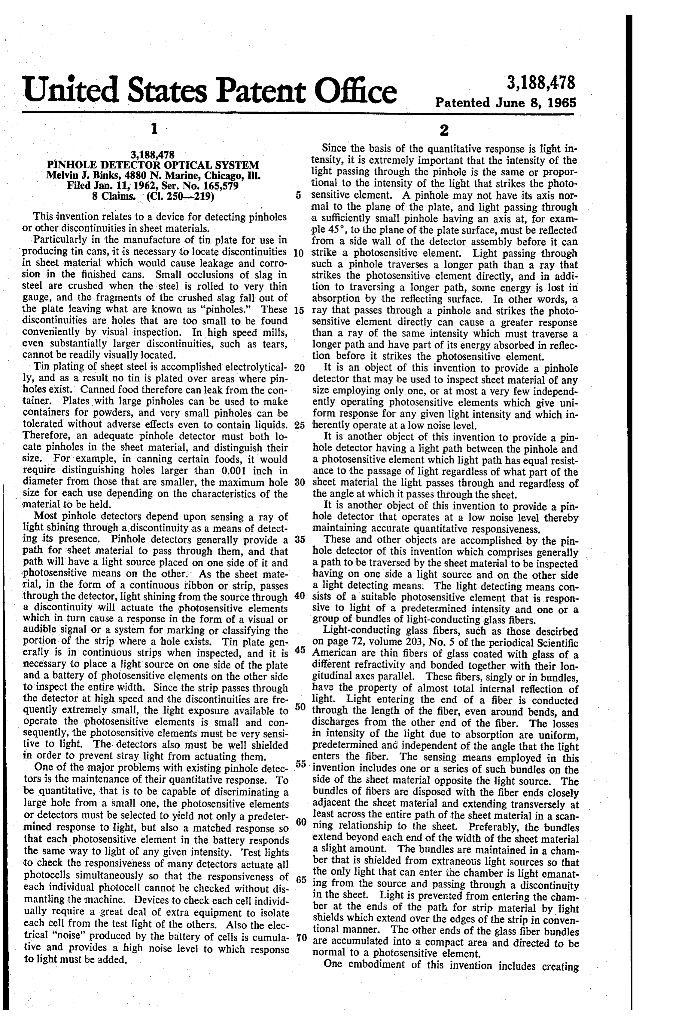
This invention relates to a device for detecting pinholes a sufficiently small pinhole having an axis at, for exam or other discontinuities in sheet materials. ple 45, to the plane of the plate surface, must be reflected ..Particularly in the manufacture of tin plate for use in from a side wall of the detector assembly before it can producing tin cans, it is necessary to locate discontinuities 10 strike a photosensitive element. Light passing through in sheet material which would cause leakage and corro such a pinhole traverses a longer path than a ray that sion in the finished cans. Small occlusions of slag in strikes the photosensitive element directly, and in addi steel are crushed when the steel is rolled to very thin tion to traversing a longer path, some energy is lost in gauge, and the fragments of the crushed slag fall out of absorption by the reflecting surface. In other words, a the plate leaving what are known as "pinholes." These 5 ray that passes through a pinhole and strikes the photo discontinuities are holes that are too small to be found sensitive element directly can cause a greater response conveniently by visual inspection. In high speed mills, than a ray of the same intensity which must traverse a even substantially larger discontinuities, such as tears, longer path and have part of its energy absorbed in reflec cannot be readily visually located. tion before it strikes the photosensitive element. Tin plating of sheet steel is accomplished electrolytical 20 It is an object of this invention to provide a pinhole ly, and as a result no tin is plated over areas where pin detector that may be used to inspect sheet material of any holes exist. Canned food therefore can leak from the con size employing only one, or at most a very few independ tainer. Plates with large pinholes can be used to make ently operating photosensitive elements which give uni containers for powders, and very small pinholes can be form response for any given light intensity and which in tolerated without adverse effects even to contain liquids. 25 herently operate at a low noise level. Therefore, an adequate pinhole detector must both lo It is another object of this invention to provide a pin cate pinholes in the sheet material, and distinguish their hole detector having a light path between the pinhole and size. For example, in canning certain foods, it would a photosensitive element which light path has equal resist require distinguishing holes larger than 0.001 inch in ance to the passage of light regardless of what part of the diameter from those that are smaller, the maximum hole 30 sheet material the light passes through and regardless of size for each use depending on the characteristics of the the angle at which it passes through the sheet. material to be held. It is another object of this invention to provide a pin Most pinhole detectors depend upon sensing a ray of hole detector that operates at a low noise level thereby light shining through a discontinuity as a means of detect maintaining accurate quantitative responsiveness. ing its presence. Pinhole detectors generally provide a 35 These and other objects are accomplished by the pin path for sheet material to pass through them, and that hole detector of this invention which comprises generally path will have a light source placed on one side of it and a path to be traversed by the sheet material to be inspected photosensitive means on the other. As the sheet mate having on one side a light source and on the other side rial, in the form of a continuous ribbon or strip, passes a light detecting means. The light detecting means con through the detector, light shining from the source through 40 sists of a suitable photosensitive element that is respon a discontinuity will actuate the photosensitive elements sive to light of a predetermined intensity and one or a which in turn cause a response in the form of a visual or group of bundles of light-conducting glass fibers. audible signal or a system for marking or classifying the Light-conducting glass fibers, such as those descirbed portion of the strip where a hole exists. Tin plate gen 45 on page 72, volume 203, No. 5 of the periodical Scientific erally is in continuous strips when inspected, and it is American are thin fibers of glass coated with glass of a necessary to place a light source on one side of the plate different refractivity and bonded together with their lon and a battery of photosensitive elements on the other side gitudinal axes parallel. These fibers, singly or in bundles, to inspect the entire width. Since the strip passes through have the property of almost total internal reflection of the detector at high speed and the discontinuities are fre 50 light. Light entering the end of a fiber is conducted quently extremely small, the light exposure available to through the length of the fiber, even around bends, and operate the photosensitive elements is small and con discharges from the other end of the fiber. The losses sequently, the photosensitive elements must be very sensi in intensity of the light due to absorption are uniform, tive to light. The detectors also must be well shielded predetermined and independent of the angle that the light in order to prevent stray light from actuating them. enters the fiber. The sensing means employed in this One of the major problems with existing pinhole detec- . 55. invention includes one or a series of such bundles on the tors is the maintenance of their quantitative response. To side of the sheet material opposite the light source. The be quantitative, that is to be capable of discriminating a bundles of fibers are disposed with the fiber ends closely large hole from a small one, the photosensitive elements adjacent the sheet material and extending transversely at or detectors must be selected to yield not only a predeter least across the entire path of the sheet material in a scan mined response to light, but also a matched response so 60 ning relationship to the sheet. Preferably, the bundles that each photosensitive element in the battery responds extend beyond each end of the width of the sheet material the same way to light of any given intensity. Test lights a slight amount. The bundles are maintained in a cham to check the responsiveness of many detectors actuate all ber that is shielded from extraneous light sources so that photocells simultaneously so that the responsiveness of 65 the only light that can enter the chamber is light emanat each individual photocell cannot be checked without dis ing from the source and passing through a discontinuity mantling the machine. Devices to check each cell individ in the sheet. Light is prevented from entering the cham. ually require a great deal of extra equipment to isolate ber at the ends of the path for strip material by light shields which extend over the edges of the strip in conven each cell from the test light of the others. Also the elec tional manner. The other ends of the glass fiber bundles trical "noise" produced by the battery of cells is cumula 70 are accumulated tive and provides a high noise level to which response into a compact area and directed to be to light must be added. normal to a photosensitive element. One embodiment of this invention includes creating
Page 3
equivalent optical paths or optical paths that provide Referring to the drawings, a continuous piece of sheet equal intensity losses or light absorption between the pin material 10 is passed through the device by the operation hole and the photosensitive element regardless of the of rollers 11 which drive the sheet material in the direc position or angle of the pinhole. The creation of equiv tion of from left to right as depicted in the drawings. A alent optical paths can be accomplished in several ways.
One method is to make all of the fiber bundles exactly. path for the sheet material is defined between a chamber 12, which is opaque and arranged to exclude any extrane the same length. Bundles conducting light from the edges ous light, and light sources 15, 15' and 15' which are of the sleet path will, in this embodiment, extend directly maintained in a chamber 13. Conventional light shields from one of their flat end faces to the other, while bundles employed around the edge of the sheet, which are not sensing from the center of the path will follow a more O shown, will be employed tortuous route between their end faces. Equivalent opti from extraneous light. to maintain chamber 12 sealed cal length may also be obtained by employing filters on The detection assembly is placed within the opaque the ends of shorter bundles to absorb the amount of light chamber 12. The detection assembly includes a photo energy equivalent to the absorption of the extra length sensitive element 16 and one or a plurality of fiber bundles, of the longest bundles. shown here as seven bundles numbered 17-23. An addi Light passing through a pinhole and impinging on the photosensitive element creates an electrical response from tional bundle 25 passes through the wall of chamber 12 the photosensitive element. This response is amplified, lamp 27,second into a that lightproof chamber 26 which contains a test is used intermittently to test both the quan after which it actuates means for signaling the presence titative and qualitative of, counting, marking, or otherwise locating the pinhole. 20 ment 16. Photosensitive response element of photosensitive ele 16 is connected through
The means responsive to the photosensitive element may the wall of chamber 12 to A.C. amplifier operate flaps or baffles to sort subsequently cut individual a conductor 30. The A.C. amplifier 28 28 is by means of connected to sheets with pinholes from sheets that have no discontinui ties. Employing the output of the photosensitive element ausual source through conductors 31 and is employed in the to operate other sorting or identifying means is a modi 25 elementwayto toa substantially convert the signal from the photosensitive larger but proportional signal fication considered within the scope of this invention. that is carried by conductors 32 to a device shown here as The light source employed preferably is one or more lamps that are operated with either D.C. or A.C. at high ameans marker 33, which could also be a classifier or other frequency. In modern mills, the sheet material passes terial 10.for sorting or identifying portions of the sheet ma through a pinhole detector at an extremely high speed 30 The glass fiber bundles, as heretofore stated, consist of and the exposure time in the detector is very brief. For example, at 60 cycles per second A.C. and with the strip bundles of parallel glass fibers that are bonded to and passing through the detector at 3000 feet per minute, five tion. Thesebybundles surrounded a glass having a different index of refrac inches of strip will pass through the detector per half small in diameter thatare composed of fibers that are so cycle, or per pulse, and pinholes that are two inches apart 35 and may even be flexible in maythey be bent around corners might not be individually detected. However, when the feature of these bundles is that the lightTheentering bundles. characterizing the end lamp is operated with a high frequency, for example of each fiber is transmitted through the fiber with substan 10,000 cycles per second, there will be 33 pulses per inch tially complete internal reflection whereby it discharges at that strip speed. The frequency of the light can easily from the other end without losses through the fiber wall. be selected for the particular strip speed and sensitivity 40 Intensity losses due to absorption are experienced in pass required in each case, and for most cases many pulses per ing through the fiber, but these are uniform, predictable inch of strip should be provided. When a continuous and predetermined per unit of fiber length.
D.C. light source is employed, a D.C. amplifier may be employed. However, when a D.C. source is used, it is tionOther materials that are capable of providing this func preferred to employ a high frequency chopper in either 45 the scopegreater
or lesser degree may be employed within this invention. Such material as rods or the optical or electrical circuit to create a square wave signal. This expedient is preferred because an A.C. am as Lucite or Plexiglas,methacrilate, tubes of poly methyl known commercially optical glass with polished or plifier can then be used which is advantageous because of silvered the inherently greater range that A.C. amplifiers have as employed;exterior surfaces and similar materials may be compared with D.C. amplifiers. A chopper in the optical 50 ly to insure that theirthese however materials must be used cautious optical properties are not exceeded.
circuit may consist of a perforated or slotted disc rotat For example, lateral transmission ing at high speed between the discharge end of the fiber bends or where the cross section isofdiminished, light, particularly at can pro bundles and the photosensitive element. A chopper in duce losses that will seriously affect the quantitative re the electrical circuit, such as a multivibrator, may also be Ee of the detector over certain portions of the strip used between the photosensitive element and the amplifier. path.
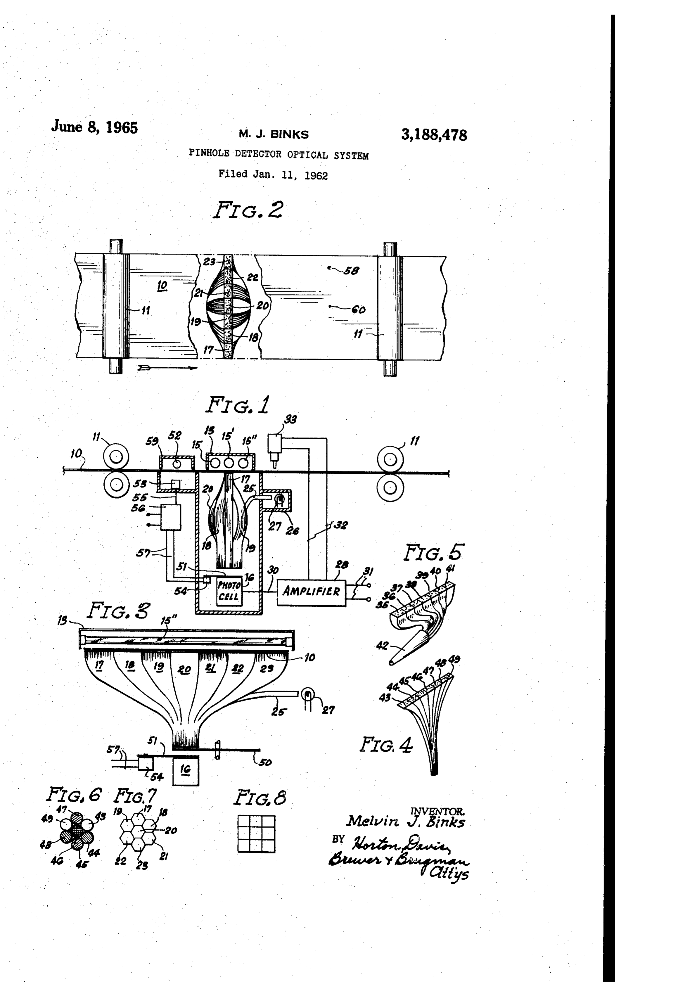
The accompanying drawings illustrate a presently pre The invention contemplates employing fiber bundles ferred embodiment of this invention. of the same absolute length so that light from a pinhole at FIG. 1 shows a partly sectional, partly schematic ele any portion of the width of the sheet material 10 will pass vation view. of a pinhole detector embodying this inven through tion; the same length of fiber in being transmitted 60 from the pinhole to the photosensitive element. The fiber
FIG. 2 shows a partly cut-away plan view of the de bundles shown in FIGS. 1, 2, 3 and 5 illustrate several tector shown in F.G. 1; variations of such equal optical length. It may be noted FIG. 3 is an enlarged view from the right side of por that bundles 17 and 23 must pass laterally from the edge tions of the pinhole detector shown in FIG. 1; of plate 10 to a position immediately above photosensi FIG. 4 illustrates one suitable arrangement of fibre tive element 16 and in so doing must traverse a greater bundles wherein each bundle is drawn and tapered; distance than the bundle 20 which is positioned directly FIG. 5 shows another suitable arrangement of fiber above bundles wherein all bundles are the same length, are ar of travelphotosensitive is compensated element 16. This additional length for by causing bundle 20 to bulge ranged to direct the light approximately 90° from the longitudinally with respect incident rays and terminate in a single light conductor; and 70 the amount that burdles 17toand sheet material 10 in exactly 23 must bulge laterally.
FIGS. 6, 7 and 8 are cross-sections of appropriate In other words, the length of each bundle between the bundle endings accumulated compactly to discharge light end face adjacent sheet material 10 and the end face ad into a photosensitive element, and these figures are not jacent photosensitive element 16 is the same. intended to be to scale or to represent sizes relative to each other. In FIG. 5 bundles identified with numerals 35 through 41 consecutively illustrate a modification of this invention
Page 4
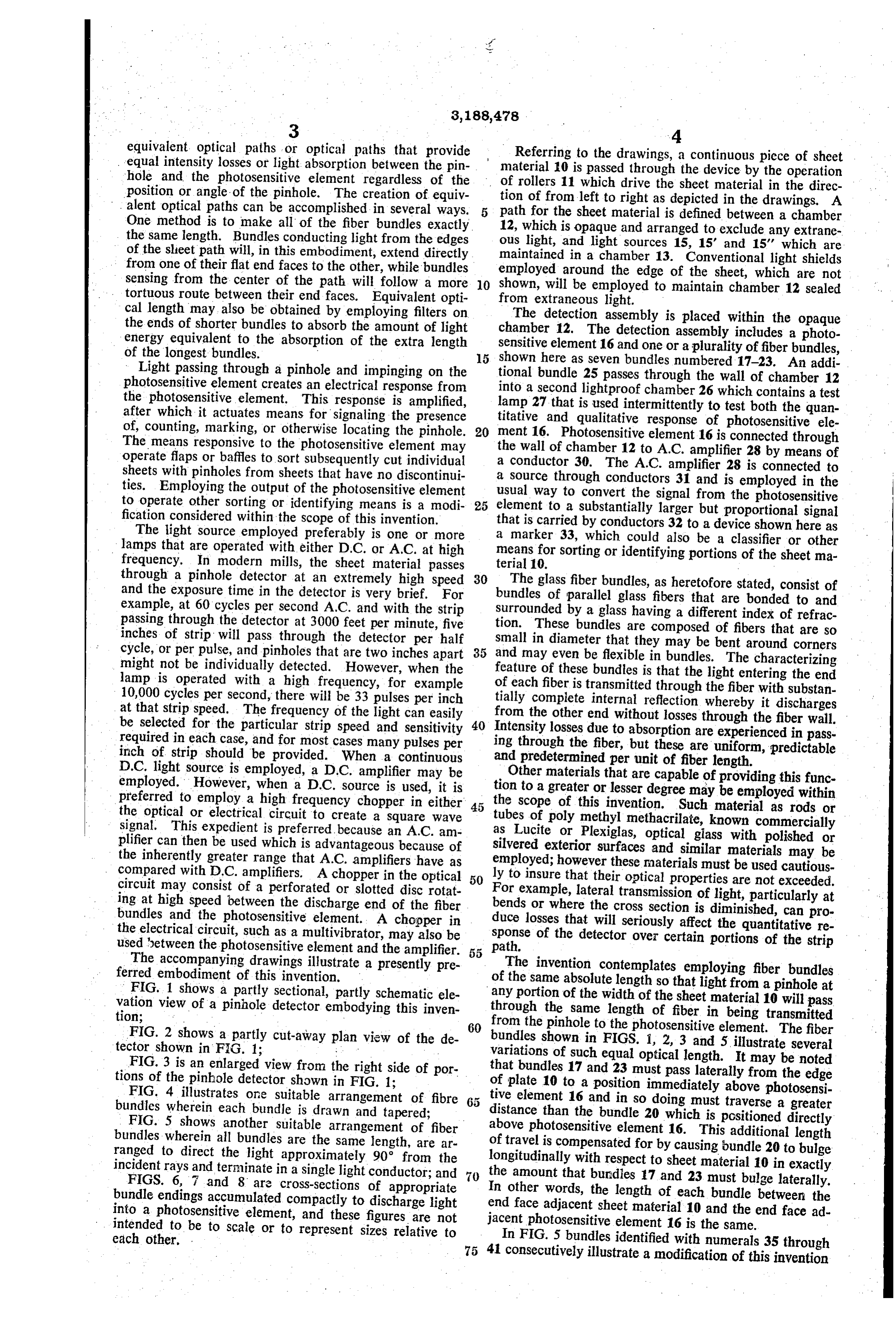
wherein the fiber bundles which are all of the same length light sources and chamber 12. When the sheet runs out, traverse paths with greater or lesser degrees of directness photosensitive element 16 is exposed to relatively intense so that they all travel the same distance between the light for a relatively long period. Such exposure causes planes in which their opposite end faces lie. The bundles a sensitive cell to become highly emissive and to operate of FIG. 5 also illustrate another advantage of this inven with a high noise level for several hours. As heretofore tion in that the bundles are all bent through a 90° turn so explained, the response of a photosensitive element is that the photosensitive element may be mounted hori added to the noise level, and a high noise level will change zontally whereby it is convenient to install and adjust and the quantitative response of such a photosensitive element. it requires much less vertical space. It is therefore very desirable to avoid a high noise level. Also in this embodiment, a large diameter single fila O Shutter 51 may be actuated by an additional light source ment fiber 42 that has been drawn to a conical shape is 52 that is positioned within a chamber 59 to actuate a optically connected to the end faces of one side of the photosensitive element 53 which is much less responsive bundles 35-41 so that light entering the wide end of fila to light than photosensitive element 16. The sensitivity ment 42 is concentrated to discharge through a substan of element 53 is such that the small amount of light shin tially smaller area from the narrow end. This means of 5 ing through an ordinary discontinuity will not actuate it. concentrating the light permits a rather wide end face Only direct exposure as when no sheet material is be on the fiber bundles to actuate a relatively small photo tween the source and the sensitive element will cause a sensitive element, such as an ordinary photoelectric cell response. The photosensitive element is connected with or photovoltaic p-n junction cell. Optical systems for conductor 55 to an amplifier 56 which operates through concentrating light may also include lenses, a conical tube 20 conductors 57 to energize the means 54 which in turn with silvered interior, a conical bar with silvered exterior, causes shutter 51 to operate.
a light gathering sphere which is a hollow sphere placed The pinhole detector of this invention functions as fol over the ends of the fiber bundles and having its interior lows. Rollers 11 drive sheet material from left to right coated with light reflecting material. A photosensitive through the pinhole detector. As the ribbon passes element preferably at 90 from the axis of the bundles, 25 through the detector, it comes between light sources 15, opens within the sphere. Other concentrating means and 15 and 15', and photocell 16. Immediately below the various combinations of the above may also be used. sheet material 10 are disposed the end faces of a series of FIG. 4 illustrates an embodiment wherein the cross glass fiber bundles which end faces extend transversely at section of each fiber bundle 43-49, inclusive, is reduced by least across the entire width of the sheet material. The such means as heating the bundle after it is formed and 30 fibre bundles 17-23 and the photosensitive element 16 drawing it to a lesser diameter. The discharge end of are enclosed in a chamber 12 to be in total darkness. such a group of bundles is concentrated into a small com When a pinhole passes between the sources and the end pact area which would appear as in FIG. 6. In the en faces of bundles 17-23, the light passing through the pin bodiment illustrated in FIG. 4, the bundles are of different hole enters the end face of one of the fiber bundles and lengths, bundles 43 and 49 being the longest, bundles 44 35 is conducted through the bundle to discharge into photo and 48 being next longest, bundles 45 and 47 being next sensitive element 16. If the pinhole is big enough, the to the shortest and bundle 46 being the shortest. In such intensity of the light passing through it will be sufficient a group of bundles, the longer bundles will absorb more to actuate the photosensitive element 16, as by discharg light than the shortest one which will affect the quantita ing a photoelectric cell, which results in an output pass tive response of the photosensitive element to light from 40 ing through conductor 30 that is amplified to sufficient the various bundles. To overcome this difficulty and re magnitude to actuate locater 33. Locater 33 is timed and tain equivalent optical characteristics, filters of different positioned to place a locating mark such as a dent or absorptivity may be placed over the ends of some bundles. scratch on the sheet material 10, as shown at 58 in FIG. As illustrated in FIG. 6, identical filters may be placed 1, at the portion of the sheet that was directly below lamp over the ends of bundles 44 and 48 to absorb the amount 15 at the time that the photocell was actuated, thereby of light discharging from those bundles that is equivalent locating pinhole 60.
to the absorption due to the extra length of bundles 43 From the foregoing description, it is evident that the and 49. Filters of even greater density may be placed pinhole detector of this invention is capable of highly over the ends of bundles 47 and 45 to absorb light equiv accurate response of both qualitative and quantitative alent to the extra length of bundles 49 and 43 and an even 50 nature. The use of a single photosensitive element, or denser filter may be placed over the end of bundle 46, at most a very few which operate independently with dif which is the shortest bundle to absorb light equivalent ferent bundles, reduces the electrical noise many-fold, it to the extra length of bundles 49 and 43. Bundles 49 and makes periodic testing of the accuracy of the response 43 require no filters and are shown without them. Thus it more easily and accurately accomplished and it produces is that all of the bundles will comprise light conducting significant savings both in the construction and mainte paths of equal light transmissivity. nance of the device.
The light bundles may terminate in hexagonal cross A single photosensitive element may be used because of sections as shown in FIG. 7 or in some pattern of square the fiber bundle light transmitters in the detection assem cross-sections as shown in FIG. 8, and one bundle ending bly. The bundles, besides permitting the use of a single may be for the test light bundle 25, although it may be 60 photosensitive element, conduct light from a pinhole to tapped into one of the other bundles to preserve a com the photosensitive element with predetermined and equal pact cross-section at the discharge end. intensity losses that can be accounted for in designing In FIG. 3 parts of the optical path are shown in greater quantitative responsiveness.
detail. These include a mechanical chopper 50 in the Having thus described the invention, what I claim is: form of a perforated or slotted disk that rotates on a shaft, 1. In a pinhole detector for detecting holes in a rapidly which is employed when the light sources function on
D.C. energy and an A.C. amplifier is used. The chopper moving continuous sheet of material having two major surfaces, the means including a light source, a photosensi 50 creates a high frequency square wave voltage in photo tive sensitive element 16 and amplifier 28 receives that out mentelement, means actuated by said photosensitive ele for indicating the presence of a hole in said sheet of put as an A.C. voltage which is amplified to a proportion 70 material, means defining a path between said light source ately larger A.C. voltage in lines 32.
and said photosensitive
FIG. 3 also shows a light stop or shutter 51 which is continuous sheet of material, element for said rapidly moving placed to prevent light from the fiber bundles from enter posed said light source being dis ing photosensitive element 16. The light stop or shutter adjacent to and across said path for directing light is employed when no sheet material 10 is between the 75 against one major surface of said sheet of material, and means shielding said photosensitive element from extra
Page 5
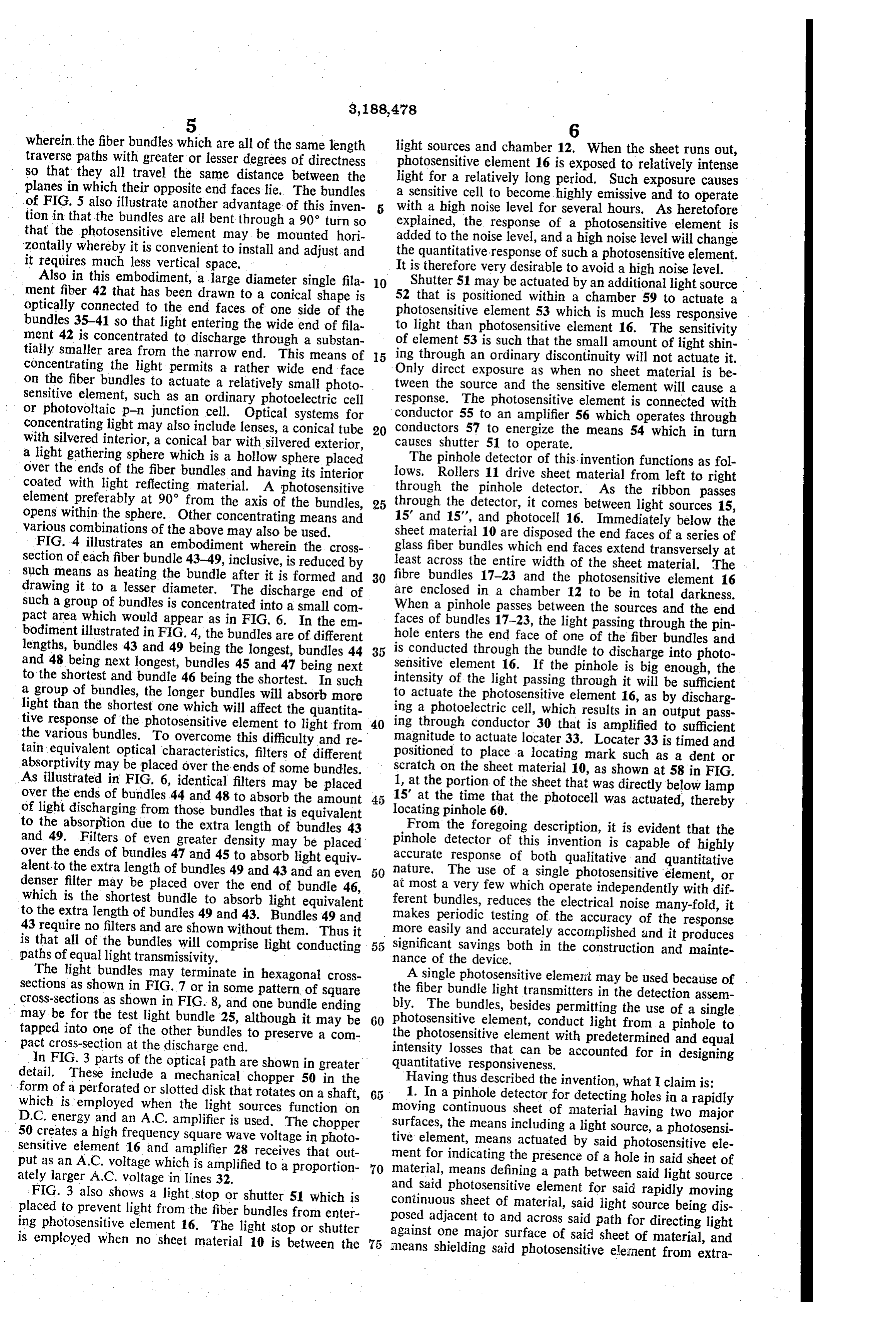
neous light; the means comprising a plurality of separate means actuated by said photosensitive element for indi elongated light conductors each having a first end, and cating the presence of a hole in said sheet of material, a second end, said first end including an end face disposed means defining a path between said light source and said adjacent to and in scanning relationship to the other major photosensitive element for said rapidly moving continuous surface of said sheet of material, said first ends of said sheet of material, said light source being disposed adjacent plurality of light conductors being in side-by-side relation to and across said path for directing light against one ma ship and said end faces thereof being aligned with and jor surface of said sheet of material, and means shielding confronting said light source whereby light from said said photosensitive element from extraneous light; the light source impinges upon at least one of said end faces means comprising a plurality of separate elongated light when a hole in said sheet of material passes said light O conductors each having a first and a second end, said first source, each of the second ends of said plurality of light end including an end face disposed adjacent to and in scan conductors having an end face disposed to discharge con ning relationship to the other major surface of said sheet ducted light into said photosensitive element. of material, said first ends of said plurality of light con 2. The detector of claim 1 in which each of said plu ductors being in side-by-side relationship and said end rality of light conductors comprises a bundle of light faces thereof being aligned with and confronting said conducting fibers. light source whereby light from said light source impinges 3. The detector of claim 1 in which each of said plu upon at least one of said end faces when a hole in said rality of light conductors defines a light path of substan sheet of material passes said light source, each of said sec tially equal light transmissivity. ond ends of said plurality of elongated light conductors 4. The detector of claim 3 in which a filter that absorbs 20 having a second end face, each of said second end faces light is disposed over an end face of a first of said plu discharging conducted light into said photosensitive ele rality of light conductors to create a light path of light ment of a generally uniform intensity in response to a uni transmissivity equivalent to the light transmissivity of a form light input at each of said first end faces. second of said plurality of light conductors.
5. The detector of claim 2 in which each of said plu 25 References Cited by the Examiner rality of light conducting bundles is tapered with the end m UNITED STATES PATENTS face thereof in scanning relationship having a larger area 2,256,595 9/41 Metcalf -------------- 250-227 than the end face thereof disposed to discharge light into 2,410,104 10/46 Rainey --------------- 250-227 . said photosensitive element.
6. The detector of claim 1 in which light responsive 30 2,563,274
shutter means intercepts light between said light conduc 2,669,354 2/54 Perrin ------------- 250-227 X tors and said photosensitive element when no sheet mate 2,892,951 6/59 Linderman ----------- 250-220 rial is in said detector.
7. The detector of claim in which said light source 2,945,958 7/60 Morris --------------- 250-230
includes a D.C. lamp and chopper means is interposed 35 3,114,283 between said light conductors and said photosensitive 12/63 Gruner ------------ 250-227 X element.
8. In a pinhole detector for detecting holes in a rapidly RALPH. G. NILSON, Primary Examiner, moving continuous sheet of material having two major ARCHIE R. BORCHELT, Examiner.
surfaces including a light source, a photosensitive element, 40
Provenance
- Collection
- Cited prior art
- Original PDF
- patentimages.storage.googleapis.com →
- Filed
- 1962-01-11
- Pages
- 5
- Method
- pdftotext (the PDF's own text layer) + pdftoppm 300dpi page scans
- Source
- Google Patents bibliographic record
- Granted
- 1965-06-08
- Inventors
- Melvin J Binks
- Transcribed from
- patentimages.storage.googleapis.com →