patent · US4781165
Internal combustion engine pollutant control system
1 November 1988
Page 1 — bibliographic record
United States Patent (19) 11 Patent Number: 4,781,165 Rawlings 45 Date of Patent: * Nov. 1, 1988 (54 INTERNAL COMBUSTION ENGINE 4,216,751 8/1980 Davison et al. ..................... 123/557 POLLUTANT CONTROL SYSTEM 4,233,945 11/1980 Beitz. .............. ... 123/557 4,274,383 6/1981 Adams ... ... 123/523 75 Inventor: Kelly R. Rawlings, Big Bear Lake, 4,303,051 12/1981 Weishaar ... ... 123/557 Calif. 4,306,531 12/1981 Watkins .. ... 123/557 73) Assignee: Anti-P, Inc., Los Angeles, Calif. 4,319,554 3/1982 Buffie ..... ... 123/559 4,345,141 8/1982 Little ...... ... 219/207 * Notice: The portion of the term of this patent 4,345,570 8/1982 McNeece ... 123/557 subsequent to Dec. 8, 2004 has been 4,356,805 11/1982 Kler ............ ... 123/557 disclaimed. 4,362,131 12/1982 Mason et al... ... 123/41.1
(21) Appl. No.: 106,715 4,370,970 2/1983 Kunz .. ... 123/557 4,391,259 7/1983 Urban ..... ... 123/557 22 Filed: Oct. 6, 1987 4,398,523 8/1983 Henson ... ... 123/557 4,411,240 10/1983 Kravetz .................... ... 123/557
Related U.S. Application Data 4,429,675 2/1984 Talbert ...................... ... 123/557 .
63) Continuation of Ser. No. 853,425, Apr. 23, 1986, Pat. 4,519,358 5/1985 Redele ........ ... 123/557 No. 4,711,222, which is a continuation-in-part of Ser. 4,711,222 12/1987 Rawlings ............................. 123/555
FOREIGN PATENT DOCUMENTS
(51 Int. Cl. ............................................. F02M 31/12 52 U.S. Cl. .................................... 123/555; 123/525; 56-83559 7/1981 Japan ................................... 123/549 123/549; 123/552; 123/592; 261/69.1; 261/142 Primary Examiner-Andrew M. Dolinar 58 Field of Search ............... 123/555, 557, 552,549, Attorney, Agent, or. Firm-Kelly, Bauersfeld & Lowry
56) References Cited (57) ABSTRACT
includes a fuel heater and vaporizer unit which pro 1,980,496 11/1934 Musselwhite . duces a 30% liquid/70% vapor fuel mixture for deliv 2,205,750 6/1940 Ross .................................... 123/555 ery to the carburetor, and a flow control valve con 2,285,905 6/1942 Cunningham et al. ............. 123/557 nected to be responsive to the ported vacuum pressure 2,306,897 12/1942 Ollig ......... 123/557 in the carburetor to increase the flow of heated and 2,717,827 9/1955 Best ....................................... 48/144 vaporized fuel to the carburetor when the ported pres 2,884,917 5/1959 Quinby . sure decreases, and decrease the flow of such heated 3,184,295 5/1965 Baverstock ......................... 123/557 3,544,290 12/1970 Larson, Sr. et al. ................ 123/592 and vaporized fuel when the ported pressure increases. 3,850, 152 11/1974 Hollins. The air drawn into the carburetor as a result of engine 3,931,800 1/1976 Gendron . operation is further heated to a temperature within the 3,931,801 1/1976 Rose et al. .......................... 123/557 range 160' F. to 180° F., by thermister controlled heat 3,933,135 1/1976 Zillman et al. . ing elements. In operation, the flow control valve 3,963,013 6/1976 Authement et al. . works in conjunction with the carburetor float chamber 3,968,775 7/1976 Harpman ........................... 123/25 B to provide varying amounts of heated liquid fuel and 4,020,815 5/1977 Hubert ................................ 123/556 heated vaporized fuel for mixing within the carburetor 4,040,403 8/1977 Rose et al. .......................... 123/557 4,092,963 6/1978 Vrooman ............................ 26/142 with the heated air, to enhance combustion within the 4,106,453 8/1978 Burley .......... ... 261/41 A engine and produce a corresponding reduction in ex 4,141,327 2/1979 Marcoux et al. .................... 123/549 haust pollutants.
4,213,433 7/1980 Day ..................................... 123/549 23 Claims, 4 Drawing Sheets
SSSN YS
iSNRSS
dawahir
Page 2
Drawing sheet — no readable text.
Page 3
Drawing sheet — no readable text.
Page 4
Drawing sheet — no readable text.
Page 5
Drawing sheet — no readable text.
Page 6
combustion engine are capable of providing complete
INTERNAL COMBUSTION ENGINE POLLUTANT combustion with air/fuel ratios of about 18.5:1. Air to CONTROL SYSTEM fuel ratios in this range are effective in reducing the
RELATED APPLICATION
undesirable hydrocarbon and carbon monoxide by-pro ducts of combustion.
This is a continuation of application Ser. No. 853,425, Prior proposed systems for increasing the efficiency filed Apr. 23, 1986, now U.S. Pat. No. 4,711,222, which of combustion and decreasing the levels of certain unde is a continuation-in-part of application Ser. No. 729,656, sirable combustion by-products have included appara filed May 2, 1985, now abandoned. 10 tus for heating and/or vaporizing fuel prior to injection
BACKGROUND OF THE INVENTION into the carburetor venturi, devices for preheating air before mixing the same with injected fuel, and various
This invention relates generally to internal combus other systems intended to separate the lighter from tion engines, and more specifically, to an improved heavier fuels in a mixture before mixing with air. Al system for automatically controlling the air/fuel mix though many different systems have been proposed for ture passing to the engine in a manner ensuring proper 5 increasing the efficiency of internal combustion engines operation of the engine over a wide spectrum of operat and reducing pollutants, none have proved entirely ing conditions, while simultaneously improving com satisfactory over the broad spectrum of engine operat bustion of the volatile mixture and thereby reducing ing conditions, as those commonly encountered in auto pollutants.
The usual automotive vehicle using a gasoline pow 20 mobile engines.
ered internal combustion engine includes a fuel tank, a necessary regard,
In this for a it has been found that it is not only system to be susceptable to tight control fuel pump and a carburetor. The carburetor is provided of the air/fuel ratio, but the system must also have the with a chamber for receiving gasoline from the fuel flexibility to allow change in the air/fuel ratio which pump, and a float controlled valve maintains the gaso line at a constant level in the chamber. The usual carbu 25 changes with varying load conditions. If the system retor includes a venturi through which air for combus does not have this flexibility but does have the ability to tion is drawn at substantial velocity, thus producing in maintain a constant air/fuel ratio, it would only really the venturi a pressure substantially less than atmo be effective over a desired or given operating range and spheric. This reduced pressure induces a flow of fuel would not function well outside such range. from the float chamber of the carburetor, and as the 30 Accordingly, there has been a need for an improved gasoline in liquid phase emerges from jets or nozzles internal combustion engine pollutant control system within the venturi, it is atomized or vaporized, or both, which is capable of tightly controlling the air/fuel mix and mixed with the combustion air flowing through the ture ratio received into the intake manifold, which sys venturi. ten also has the flexibility to allow a change in the The mixture of air and fuel is delivered to a manifold, 35 air/fuel ratio with changes in engine load conditions and from the manifold is drawn into the engine cylin and speed. In particular, there is a need for an improved ders during the suction strokes of the pistons therein. system which is capable of maximizing fuel efficiency in The air/fuel mixture is compressed in each cylinder automobile engines, while simultaneously permitting during the compression stroke of the piston, and is then changes in the air/fuel mixture to ensure engine respon ignited, either by a spark in the conventional engine, or 40 siveness to typical driving conditions. Such a system by compression with or without supplementary heating should preferably be adapted for use with existing car means in a diesel engine. Ideally, combustion of the buretion systems, be capable of use with such existing air/fuel mixture, which is initiated at the spark plug gap, carburetion systems while also requiring minimal modi progresses rapidly and is fully complete at the end of the fication to the same, and be constructed of components power stroke of the cylinder. Too rapid burning or 45 known to be able to withstand the rigors of long term detonation is wasteful and causes knocking. Too slow automobile engine usage. Additionally, in connection burning results in some fuel failing to burn and being with the foregoing, there is a need for a novel apparatus discharged in the exhaust. It is recognized that in the capable of safely and efficiently heating and partially usual gasoline engine a very substantial percentage of vaporizing fuel into a specific mixture, and associated fuel is wasted, and a relatively small percentage of the 50 total energy available in the fuel is converted into usable apparatus for controlling passage of the heated and partially vaporized fuel mixture to the carburetor. Such energy by the engine.
Due to the inefficiencies of prior engines, many at tion, systems and apparatus should be of simplified construc tempts have been made to improve the same by increas and maximize use of existing engine components. ing the efficiency of the associated carburetion system. 55 The present invention fulfills these needs and provides The ultimate purpose in increasing the efficiency of the other related advantages.
carburetion system for an engine is to increase the per SUMMARY OF THE INVENTION centage of fuel totally burnt in the cylinders, thereby increasing fuel economy and reducing certain undesir The present invention resides in an improved internal able combustion by-products such as hydrocarbons and 60 combustion engine pollutant control system which, in carbon monoxide, and increase other more desirable effect, modifies the carburetion of the engine to reduce combustion by-products such as carbon dioxide. exhaust pollutants while simultaneously ensuring engine It is generally accepted that reduction of harmful responsiveness to changes in carburetor throttling. To emissions could be accomplished by delivering a homo this effect, the improved system entails the heating of geneous mixture of air and fuel to the engine, thereby 65 air drawn into the carburetor to a temperature within allowing lean mixtures to be burned with complete the range of 160°F. to 180° F. Further, the fuel is heated combustion. Known state of the art carburetion-induc and vaporized prior to mixing with the heated air into a tion devices utilized with the conventional internal mixture of approximately 30% liquid fuel and approxi
Page 7
mately 70% vaporized fuel by volume at a temperature float chamber, a valve passageway connecting the valve within the range of 115 F. to 125 F. inlet to the valve outlet, a valve member situated and During an engine idle condition when the throttle is dimensioned to control the flow of fuel through the closed, only heated liquid fuel is injected into the carbu valve passageway, and means for moving the valve retor to ensure smooth operation. As the throttle is member with respect to the valve passageway. opened, however, additional quantities of heated liquid The valve moving means includes a valve shaft con fuel are momentarily injected into the carburetor, fol nected at one end to the valve member, and a flexible lowed by injection of heated vaporized fuel. As the diaphragm connected to the other end of the valve engine speed is further increased, a combination of shaft, which diaphragm is exposed on one side to atmo heated liquid fuel and heated vaporized fuel is injected O spheric pressure and on the other side to ported vacuum into the carburetor for mixing with the heated air to pressure. A spring is positioned above the diaphragm to form an appropriate explosive mixture needed for sus tained and responsive engine operation. Finally, the bias the same in a downward direction to urge the valve member to normally restrict flow through the valve system further provides that as the throttle is closed, the passageway. The tension force on the spring can be amount of heated vaporized fuel injected into the carbu 15 adjusted to meet the particular criteria needed to fine retor is decreased and eventually shut off, so that as the tune the apparatus for particular carburetion require engine again comes into an idle condition only heated ments. Additionally, a rib is provided on the valve pas liquid fuel is injected into the carburetor. sageway surface to prevent complete closure by the In a preferred form of the invention, a standard car valve member. This particular arrangement effectively buretor is utilized since the other components of the 20 permits the flow control valve to restrict the flow of system can be added to the standard carburetor to im prove virtually any existing internal combustion engine. fuel between the fuel heating and vaporizing means and For reference purposes, standard carburetors typically flowcarburetor, the while not altogether preventing any therethrough.
have a venturi mixing throat in fluid communication with an air intake at one end, and the intake manifold at 25 The aforementioned apparatus, and particularly the the other end. Such standard carburetors typically fur flow control valve, permits the carburetor float cham ther include a fuel float chamber, and a plurality of ber to remain substantially full of liquid fuel during an passages from the fuel chamber to the carburetor mix from engine idle condition, and the liquid fuel escaping there ing throat. as the engine idles is constantly replenished with In connection with this standard carburetor, the pre 30 fuel already subject to conditioning by the labyrinth. As ferred system includes at least one electrical resistance engine speed is increased, the flow control valve opens heating element situated within the air intake for heat to allow a greater amount of fuel to pass from the laby ing the air supplied to the carburetor venturi mixing rinth into the flow chamber. Because of the fuel demand throat to a temperature within the range of 165 F. to exerted by increased engine operation, the liquid fuel 175 F. The temperature of the resistance heating ele 35 level will tend to drop within the float chamber suffi ment is controlled by an air temperature sensing ther ciently to permit vaporized fuel to pass through the mister situated downstream of the resistance heating float chamber directly into the venturimixing throat for element, which functions as an on/off switch to control mixing with heated air drawn through the air intake. voltage input to the air heating element. Other features and advantages of the present inven Situated generally adjacent this air heating element is tion will become apparent from the following more a free-wheeling fan which functions to increase the detailed description, taken in conjunction with the ac turbulence of the heated air drawn into the carburetor companying drawings which illustrate, by way of ex mixing throat. It has been found that by increasing the ample, the principles of the invention. turbulence of such air, the mixing of the air and fuel within the venturimixing throat is enhanced to improve 45 BRIEF DESCRIPTION OF THE ORAWINGS combustion of the volatile mixture within the engine. The accompanying drawings illustrate the invention. A fuel heating and vaporizing means is interposed In such drawings:
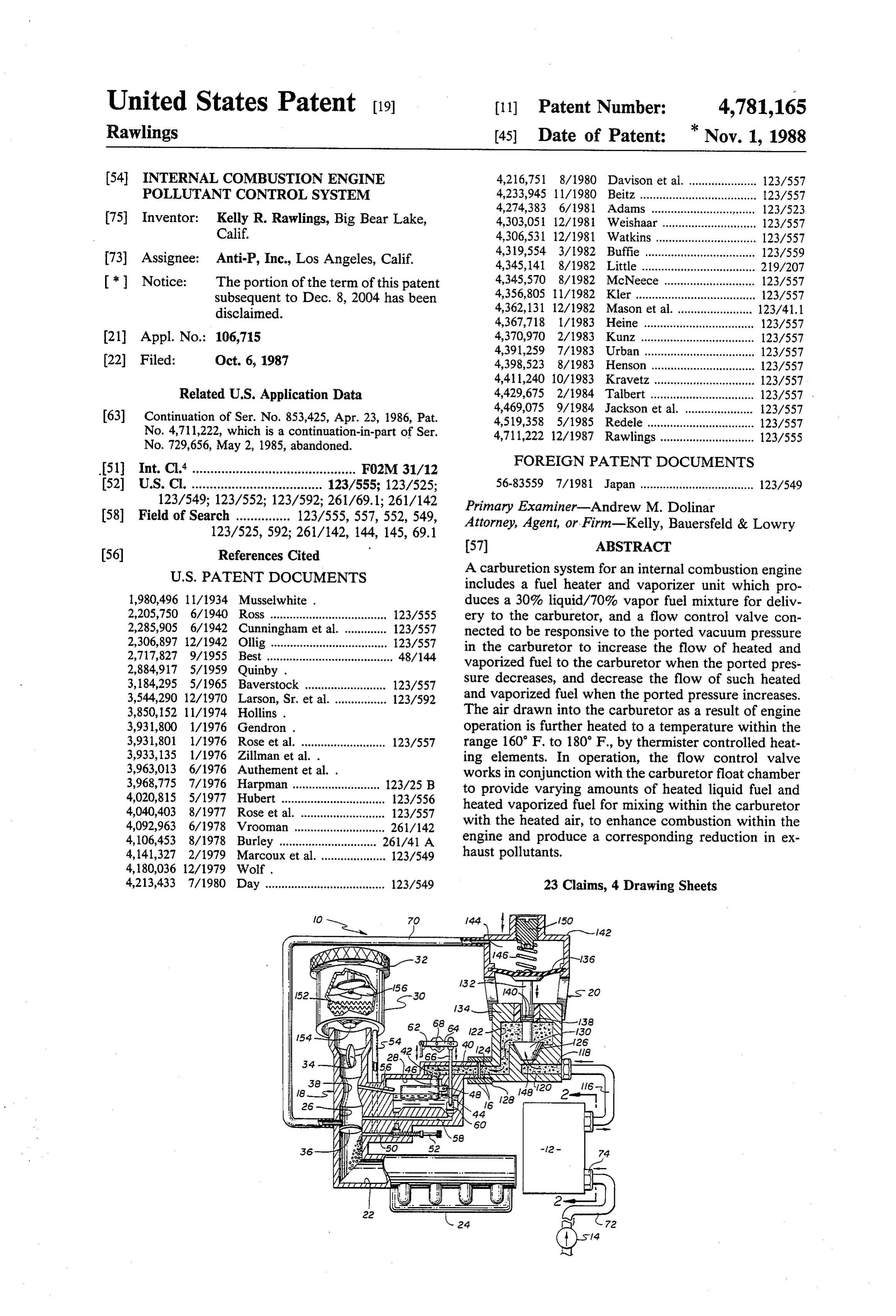
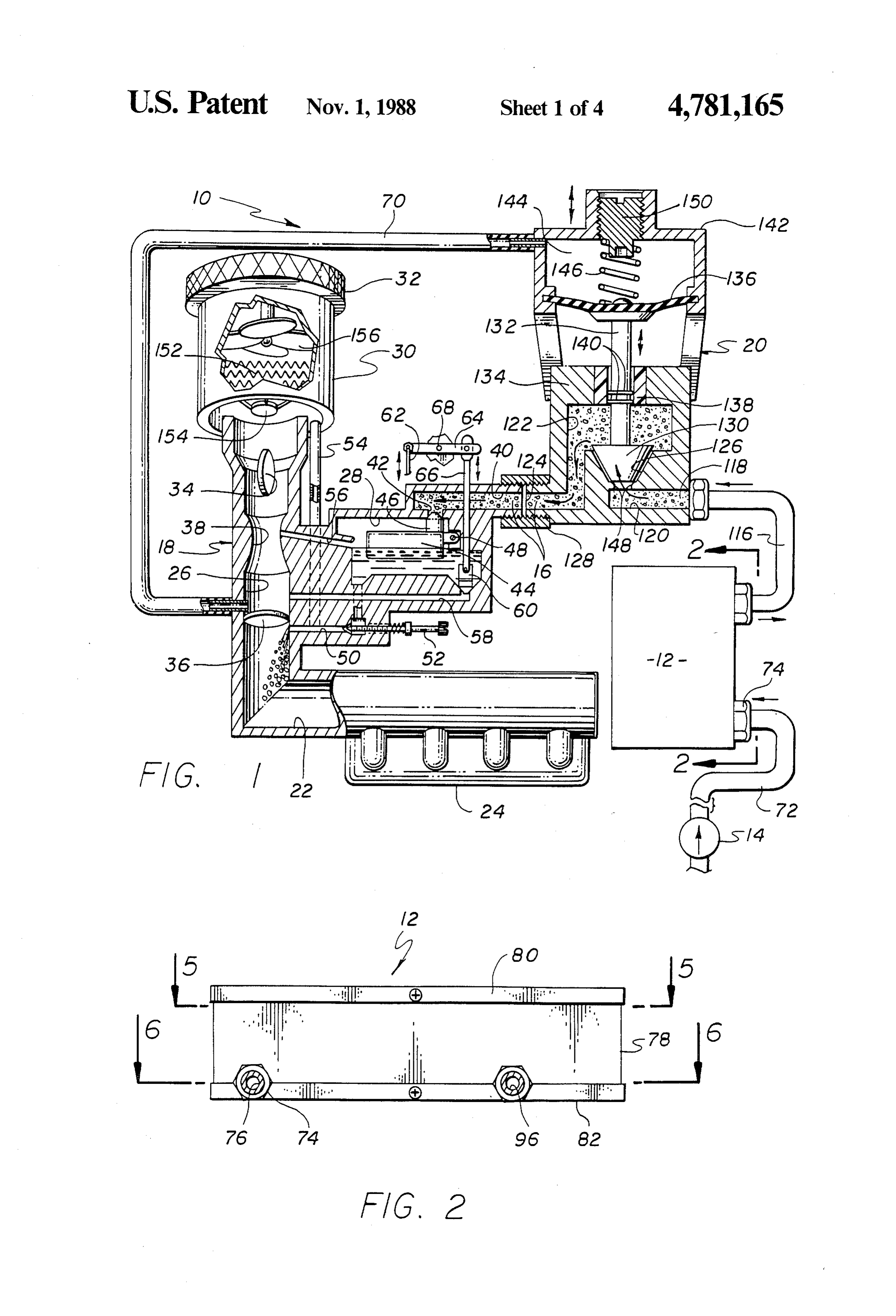
between the fuel pump and the carburetor to transform FIG. 1 is a diagrammatic illustration of a carburetion the fuel into a mixture of approximately 30% heated system for an internal combustion engine incorporating liquid fuel and approximately 70% heated vaporized 50 the improved features of the present invention, the con fuel by volume. This heating and vaporizing means figuration of the specific components being illustrated includes an electrical resistance heating element and a as they would appear during an engine idle condition; heat sink which defines a labyrinth having an inlet and FIG. 2 is an enlarged, partially sectional, elevational an outlet. Fuel temperature sensing means and a ther view of a fuel heating and vaporizing unit forming a mister are further provided to regulate the temperature 55 portion of the heat sink to ensure that the temperature of the the line of 2-2 the present invention, taken generally along of FIG. 1;
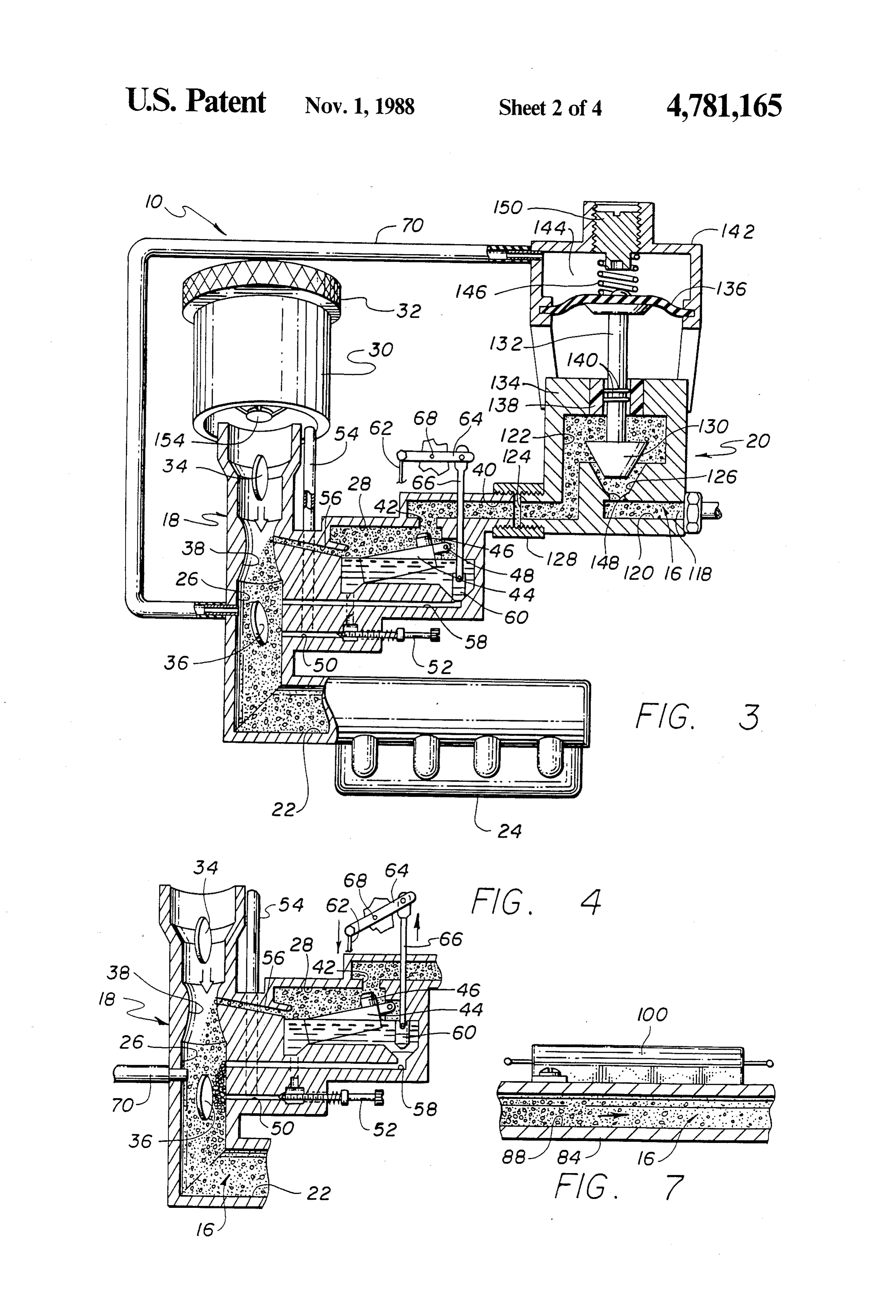
fuel mixture at the outlet of the labyrinth is within the FIG. 3 is a diagrammatic view similar to that illus range of 115 F. to 125 F. A flow constricting valve is further provided in the proximity of the labyrinth inlet trated in FIG. 1, illustrating the configuration of the to help vaporize and increase turbulence of the fuel as it particular system components as they would appear during an engine cruise condition;
enters the labyrinth.
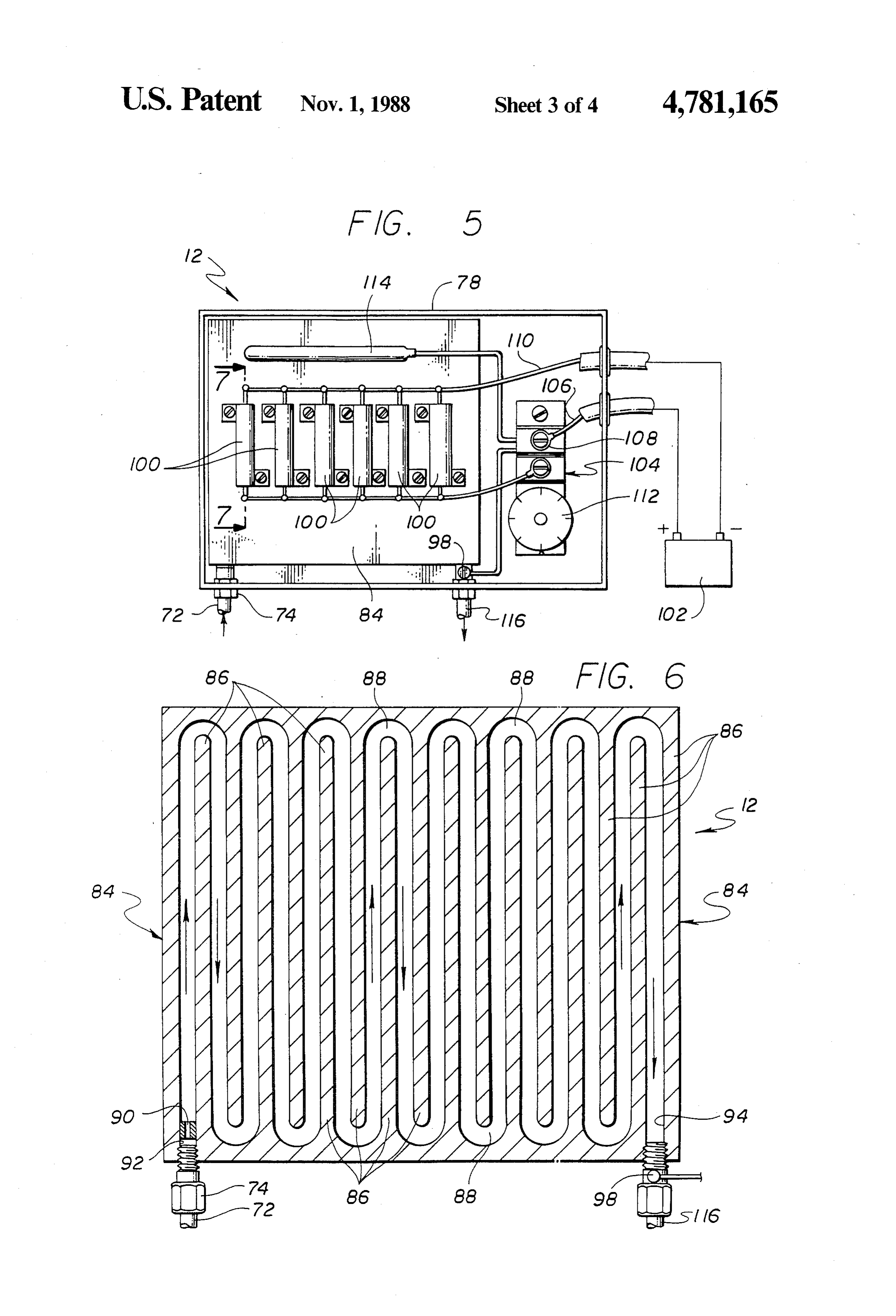
Finally, the apparatus of the presently preferred em FIG. 4 is a diagrammatic view similar to FIGS. 1 and bodiment includes means for controlling the flow of the 3, illustrating the configuration of various elements of mixture of liquid and vaporized fuel from the labyrinth the carburetor as they would appear during engine outlet to the float chamber. More specifically, this con 65 acceleration and wide open operating conditions; trolling means includes a flow control valve having a FIG. 5 is a partially diagrammatic plan view of the valve inlet in communication with the labyrinth outlet, fuel heating and vaporizing unit, taken generally along a valve outlet in communication with the carburetor the line 5-5 of FIG. 2;
Page 8
FIG. 6 is an enlarged sectional view of the fuel heat generated between a carburetor venturi 38 and the ing and vaporizing unit, taken generally along the line throttle valve, and the venturi vacuum is the negative 6-6 of FIG. 2; pressure generated between the choke valve 34 and the FIG. 7 is an enlarged sectional view of an electrical carburetor venturi.
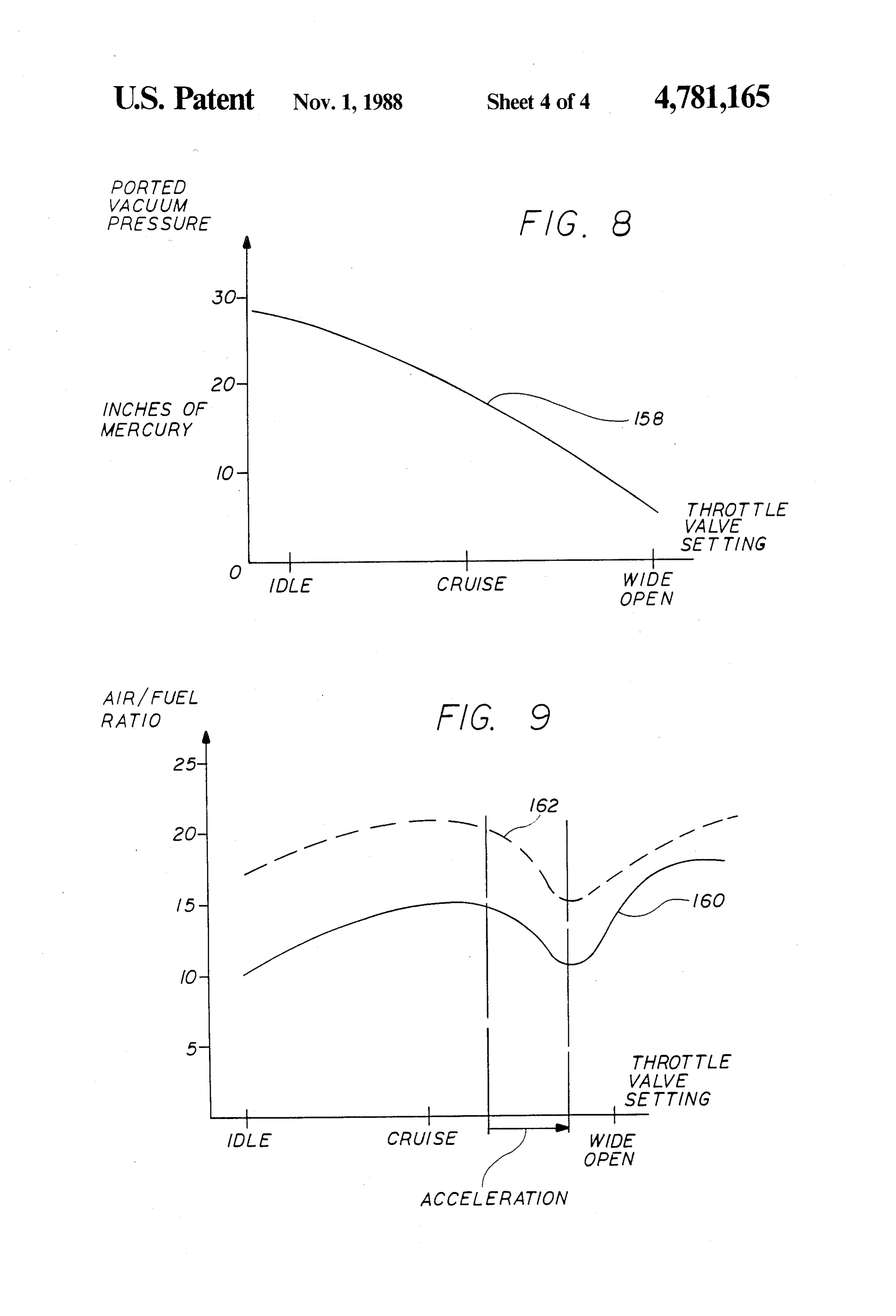
resistance heater positioned to heat a portion of a heat Fuel is pumped into the float chamber 28 from the sink within the fuel heating and vaporizing unit, taken fuel pump 14 through a carburetor fuel inlet 40 and a generally along the line 7-7 of FIG. 5; float chamber valve passageway 42. A fuel float mem FIG. 8 is a plot of ported vacuum pressure versus ber 44 having an upwardly projecting valve stem 46 is throttle valve setting; and w connected at a hinge 48 within the float chamber 28 in FIG. 9 illustrates the plots of the air/fuel ratio of a O a manner such that the float chamber passageway 42 standard carburetor with and without the addition of will be opened to fuel flow therethrough unless there is the present invention, over the operating range of an sufficient liquid fuel within the float chamber to raise engine between idle and wide open. the float 44 into a position causing the valve stem 46 to DETAILED DESCRIPTION OF THE occlude the float chamber valve passageway 42. Such 15 occlusion of the float chamber valve passageway 42 is
PREFERRED EMBODIMENT illustrated in FIG. 1.
As shown in the drawings for purposes of illustration, A plurality of fluid flow passageways are provided the present invention is concerned with an improved between the fuel float chamber 28 and the mixing throat internal combustion engine pollutant control system, 26 to permit fuel within the float chamber to be mixed generally designated by the reference number 10. This 20 with air and form a volatile mixture for delivery to the improved pollutant control system 10 broadly com cumbustion chamber means 24. A first such fuel pas prises a fuel heating and vaporizing unit 12 situated to sageway 50 forms an idle circuit which permits fuel to receive liquid fuel from a fuel pump 14 and produce a flow from the float chamber 28 to a portion of the car predetermined mixture 16 of liquid and vaporized fuel buretor 18 immediately below the throttle valve 36. The for delivering to a carburetor 18. Controlling delivery 25 flow of fuel through this idle circuit 50 is controlled by of the fuel mixture 16 from the heating and vaporizing an adjustable needle valve 52, and fuel flowing past the unit 12 to the carburetor 18 is a flow control valve 20. needle valve is mixed with air supplied from the air The improved pollutant control system 10 of this intake apparatus 30 through an idle air bleed line 54. A invention is capable of tightly controlling the air/fuel second one 56 of the aforementioned passages between mixture ratio produced at the carburetor 18 for delivery 30 the fuel float chamber 28 and the mixing throat 26 com to an intake manifold 22, which ultimately directs the prises a primary discharge tube having an inlet slightly air/fuel mixture to combustion chamber means 24. The elevated above the inlet of the fuel idle circuit 50, and improved system 10 also has the flexibility to allow an outlet which discharges fuel at the carburetor ven changes in the air/fuel mixture ratio corresponding to turi38. Finally, a third such passage 58 typically found changes in engine load conditions and speed. This is 35 in automotive carburetors comprises a power enrich particularly important if use of the improved system 10 ment circuit which, when opened to fuel flow, directs is to be feasible in automobile engines, where the fuel additional amounts of fuel into the mixing throat 26 demands of the carburetion system vary widely from between the venturi 38 and the throttle valve 36. idle engine conditions to wide open operation engine During an engine idle condition, the throttle valve 36 conditions. is completely closed, thereby preventing the creation of To better understand the technological advance ac sufficient ported vacuum pressure to draw fuel through complished by the present invention, the components the primary discharge tube 56 into the mixing throat 26. routinely associated with an internal combustion engine Sufficient manifold vacuum exists, however, in combi will hereinafter be described. The standard carburetor nation with the atmospheric pressure in the float cham (schematically illustrated in FIGS. 1, 3 and 4) includes 45 ber 28, to cause fuel to flow through the idle circuit 50 generally a mixing throat 26 and a fuel float chamber 28 into the carburetor 18. The mixture of air from the bleed which stores a measured quantity of fuel for delivery to line 54 and fuel from the idle circuit 50 may be adjusted the mixing throat as will be hereinafter described. The by means of the needle valve 52 to provide a sufficient upper end of the carburetor 18 is attached to an air air/fuel mixture to keep the engine running at idle (FIG. intake apparatus 30 which includes an air filter 32 for 50 1). As the throttle valve 36 is opened, the ported vac removing particulate matter from the air drawn into the uum pressure decreases sufficiently to draw fuel carburetor mixing throat 26. The lower end of the car through the primary discharge tube 56, and thereby buretor 18 is connected to the intake manifold 22 to supply sufficient amounts of fuel to the engine for direct the air/fuel mixture received from the mixing smooth operation thereof (FIG. 3). The power enrich throat 26 to the combustion chamber means 24. 55 ment circuit 58 is utilized when even additional amounts Situated within the air flow passageway between the of fuel are required during acceleration and wide open air intake apparatus 30 and the mixing throat 26 is a engine operation.
choke valve 34 utilized primarily to enrich the air/fuel In this regarding, a mechanical linkage is provided to mixture for cold engine starting conditions. A similar open a valve 60 situated to normally close the inlet to throttle valve 36 is disposed generally between the 60 the power enrichment circuit. This mechanical linkage mixing throat 26 and the intake manifold 22 to control includes a member 62 typically connected to the ac the various vacuum pressures created within the carbu celerater cable (not shown), a yoke 64 connected to the retor 18 as a result of air and fuel being drawn into the member 62 at one end and to a linkage shaft 66 at the combustion chamber means 24. For purposes of under other, which linkage shaft is connected opposite the standing terminology to be hereinafter used, the mani 65 yoke to the valve 60. As the throttle valve 36 is rotated fold vacuum is the negative pressure generated between to an open position (see FIG. 4), movement of the mem the throttle valve 36 and the combustion chamber ber 62 causes the yoke 64 to pivot about a hinge point means 24, the ported vacuum is the negative pressure 68, and draw the linkage shaft 66 upwardly and thereby
Page 9
remove the valve 60 from the inlet of the power enrich perature control over the fuel mixture 16 exiting the ment circuit 58. This permits additional amounts of unit outlet 96. To further prevent the fuel from becom liquid fuel to travel through the power enrichment ing heated above the desirable range, a standard ther circuit 58 into the mixing throat 26 to enrich the air/fuel mocouple 114 is placed adjacent the upper surface of mixture being delivered to the intake manifold 22. the heat sink 84 as a backup to the temperature sensor 98 In accordance with the present invention and as men (FIG. 5).
tioned briefly above, the fuel heating and vaporizing It is preferred that the fuel mixture 16 exiting the fuel unit 12 and the flow control valve 20 are disposed in the heating and vaporizing unit 12 consist of approximately fuel flow path between the fuel pump 14 and the carbu 30% liquid fuel and approximately 70% vaporized fuel retor float chamber 28. The flow control valve 20 is 10 by volume. Further, it is preferred that the temperature connected to the ported vacuum pressure within the of this fuel mixture 16 be within the range of 115 F. to carburetor mixing throat 26 by means of a ported vac 125 F.
uum line 70, and is responsive to that pressure to in The heated and partially vaporized fuel mixture 16 crease the flow of the fuel mixture 16 when the ported enters a secondary fuel line 116 as it exits the heating vacuum pressure decreases, and decrease the flow of 5 and vaporizing unit 12, which secondary line directs the fuel mixture 16 when the ported vacuum pressure that fuel mixture to an inlet 118 of the flow control increases. As will be more fully explained below, the valve 20. The flow control valve 20 includes an inlet provision of the heating and vaporizing unit 12 and the chamber 120 in open fluid communication with the inlet flow control valve 20 between the carburetor 18 and 118, an outlet chamber 122 in open fluid communication the fuel pump 14 modifies carburetion of the associated 20 with a flow control valve outlet 124, and a valve pas internal combustion engine so that during an engine idle sageway 126 connecting the inlet chamber to the outlet condition, the float chamber 28 remains substantially chamber. The flow control valve outlet 124 is shown full of liquid fuel, and such liquid fuel escaping from the connected to the carburetor fuel inlet 40 by means of a float chamber 28 through the idle circuit 50 to the mix threaded coupling 128, so that when needed, fuel may ing throat 26 is replenished with fuel already heated by 25 pass the heating and vaporizing unit. As engine speed is 12 todirectly from the fuel heating and vaporizing unit the carburetor 18.
increased, the flow control valve 20 causes the liquid A valve head 130 is connected to the lower end of a fuel level to drop within the float chamber 28 suffi valve shaft 132 and is positioned in axial alignment over ciently to permit vaporized fuel to pass into the mixing the valve throat 26 for mixing with heated air drawn through the restrict thepassageway
flow of 126 to, in some circumstances, fluid therethrough. This shaft 132 air intake apparatus 30.
Now describing the fuel heating and vaporizing unit passes through an upper wall 134 of the outlet chamber 122 and is connected at its upper end to a flexible dia 12 in more detail, and in conjunction with the detailed phragm 136. The upper wall 134 is provided with a illustrations of the same in FIGS. 2 and 5-7, liquid fuel Teflon sleeve 138 which is designed to interact with a from the fuel pump 14 typically travels through a fuel 35 line 72 connected by a suitable connector 74 to a heating pair of O-rings 140 situated about the shaft 132, to form and vaporizing unit inlet 76. The entire fuel heating and a sealmixturetherebetween and prevent the escape of any of the vaporizing unit 12 is housed within a box-like container fuel than through 16 from the flow control valve 20 other the outlet 124.
78 having a removable upper cover 80 and a similar The flexible diaphragm 136 is housed within and removable lower cover 82 (FIG. 2). Liquid fuel enter 40 extends ing the unit inlet 76 enters into a heat sink 84 which valve 20.across an upper housing 142 of the flow control This upper housing 142 is constructed so that comprises a plurality of interleaved walls 86 forming a the lower surface of the diaphragm 136 is exposed to fuel flow labyrinth passageway 88. A flow constricting atmospheric pressure, while the upper surface of the valve or orifice 90 is situated within an inlet 92 of the diaphragm is exposed solely to ported vacuum pressure.
labyrinth 88 to help vaporize the liquid fuel as it is being 45 This heated during its passage through the labyrinth. A laby is accomplished by enclosing the upper surface of rinth outlet 94 is in fluid communication with a fuel the diaphragm 136 within a vacuum chamber 144 which heating and vaporizing unit outlet 96, whereat a temper is in open communication with the ported vacuum of ature sensor 98 is preferably located to measure the the carburetor 18 through the ported vacuum line 70. A spring 146 is further provided within the chamber 144 temperature of the heated liquid and vaporized fuel 50 mixture 16 exiting the unit 12 (FIG. 6). between an upper portion of the upper housing 142 and Situated atop the heat sink 84 are a plurality of elec the upper surface of the diaphragm 146, to urge the trical resistance heating elements 100 which are electri diaphragm, and consequently the shaft 132 downwardly cally connected in parallel to one another to a battery so that when the engine is not running, the valve head 102 through an adjustable thermister 104. More particu 55 130 will rest upon a pair of ribs 148 protruding from the larly, a positive electrical lead 106 from the battery 102 valve passageway 126. The purpose of providing these passes through the container 78 for connection to the ribs 148 is to prevent the complete closure of the valve thermister 104 at a lead terminal 108. If the temperature passageway 126 to flow therethrough, so that the flow of the fuel exiting the labyrinth 88 is not within a prede control valve 20 simply controls the amount of the fuel termined temperature range, the thermister 104 will mixture 16 flowing through the valve, rather than permit passage of the voltage from the battery 102 to whether any flow is allowed through the valve at all. the heating elements 100 for purposes of heating the Presently, the ribs 148 preferably create a 0.015 inch heat sink 84. To complete the electrical connection, minimum gap between the valve passageway 126 and each of the heating elements 100 is further connected to 65 the valve head 130 when in a fully restricted position. a ground 110 which, as with the lead 106, also passes Finally, an adjustable screw cap 150 is provided through the container 78 back to the negative terminal through the upper portion of the upper housing 142, to of the battery 102. The thermister 104 includes a tem permit adjustment of the tension of the spring 146 upon perature setting knob 112 which permits precise tem the diaphragm 136.
Page 10
In addition to the foregoing, the preferred embodi In this regard, FIG. 8 shows a plot 158 of the ported ment of the present invention further includes means for vacuum pressure in the carburetor 18 given in inches of heating the air drawn through the air intake apparatus mercury, versus the throttle valve setting. It will be 30 before entering the carburetor mixing throat 26. This noted that the ported vacuum pressure is almost atmo air heating means includes a resistance heating element spheric during idle conditions. This pressure drops to 152 situated within the air intake apparatus 30, and a about eighteen or nineteen during a cruise engine oper thermister 154 situated downstream of the heating ele ating condition, and when the carburetor is wide open, ment 152 to ensure that the air drawn through the air the ported vacuum pressure may be on the order of intake apparatus 30 into the mixing throat 26 is heated to seven or eight inches of mercury. This pressure defined a temperature within the range 160 F. to 180° F. More O by the plot 158 is utilized to control actuation of the over, a free-wheeling fan 156 is situated within the air flow control valve 20 to activate the diaphragm 136. intake apparatus 30 below the air filter 32 but above the As the throttle valve 36 is further opened and the heating element 152, to increase the turbulence of the engine is taken through acceleration to a wide open heated air drawn into the carburetor mixing throat 26. operating condition (as illustrated best in FIG. 4), even The purpose of increasing the turbulence of the heated 15 greater quantities of fuel are needed to ensure smooth air is to improve mixing of the air and the fuel within the operation mechanism of the engine. In this regard, the linkage described above in connection with the carburetor to improve combustion of the resultant air/fuel mixture within the combustion chamber means 24. power enrichment circuit 58 opens to permit heated liquid fuel to pass through the power enrichment circuit
Having thus described the apparatus of the present directly invention, carburetion of an internal combustion engine 20 This into the mixing throat 26 of the carburetor 18. utilizing the improved system 10 will now be explained. heated liquid fuel, together with the heated vapor. Referring generally to FIG. 1, prior to starting the ized fuel discharging from the float chamber 28 through engine the fuel float chamber 28 will typically be full of the primary discharge tube 56, combines with the fuel, the throttle valve 36 will be closed, and the valve heated air from the air intake apparatus 30 to provide a head 130 will be positioned to maximize restriction of 5 much more readily combusted air/fuel mixture for de fuel flow through the flow control valve 20. Upon start livery to the combustion chamber means 24. Thus, from the foregoing it is to be understood that ing the engine and during an engine idle condition, the improved system 10 of the present invention can be liquid fuel will be drawn through the idle circuit 50 into readily added to existing internal combustion engine the carburetor 18 below the throttle valve 36 to provide 30 carburetion the necessary explosive mixture to maintain the engine the air/fuel systems mixture to improve the combustability of being drawn into the combustion in that idle condition. The air heating element 152 and chamber means 24, and thereby advantageously im the heat sink heating elements 100 are preferably con prove fuel efficiency while simultaneously reducing the nected to the voltage source (battery 102) so that activa level of undesirable combustion by-products. tion of the ignition system will simultaneously activate 35 Referring to FIG. 9, there is shown a plot 160 of the those heating elements. As fuel is drawn through the air/fuel ratio as a function of engine operation between idle circuit 50, the float 44 will slightly drop, thus mov idle and wide open. This plot 160 shows conditions in ing the valve stem 46 away from the float chamber the absence of the improved system 10 between the fuel valve passageway 42, and allow additional fuel to enter the float chamber 28. Gradually, the fuel entering the pump 14 and the carburetor 18. It can be seen that at idle the air/fuel ratio is about 10:1, and rises to about float chamber 28 will be heated by the fuel heating and 15:1 at cruise. After acceleration the air/fuel ratio may vaporizing unit 12 until it reaches a consistency of ap approach 16:1.
proximately 30% liquid fuel and 70% vaporized fuel by Considering now the operation of the engine carbure volume within the temperature range of 115 F. to 125 tion system when the improved system 10 is functioning F. Thus, as the engine warms up, the overall thermo 45 in response to the ported vacuum pressure illustrated in efficiency of the engine will be improved through the FIG. 8, it will be seen that at idle the air/fuel ratio is provision of heated fuel, resulting in decreased undesir above 15:1, and at cruise can increase to about 20:1. able combustion by-products in the form of pollutants. After acceleration, this air/fuel ratio may increase to As the throttle valve 36 is opened to increase engine about 21:1, and because of the relatively lean mixture, speed, air is drawn directly through the air intake appa 50 improved combustion takes place. It will be evident ratus 30, past the air heating element 152 into the carbu from the curve 162 that this air/fuel ratio throughout retor mixing throat 26. This fast moving air causes the the range of engine operation is consistently higher pressure to lower sufficiently at the carburetor venturi from idle to wide open than in the absence of the de 38 to begin to draw liquid fuel from the float chamber scribed improved system 10. These improvements are 28 through the primary discharge tube 56. The ported 55 possible without extensive modifications to existing vacuum pressure will simultaneously decrease, thus carburetors, and further without diminishing engine acting to raise the valve head 130 away from the valve performance and responsiveness.
passageway 126 against the downward biasing of the As the throttle valve 36 is moved from a wide open spring 146. The effect of heating and vaporizing the fuel configuration back to the idle condition, first the power at the fuel heating and vaporizing unit 12, and allowing 60 enrichment circuit 58 will close, and then eventually the increasing amounts of the heated fuel mixture 16 to pass heated vaporized portion of the fuel mixture 16 will through the flow control valve 20, allows the action of cease to pass through the primary discharge tube 56 into the flow control valve to override the normal function the mixing throat 26. Further, since the ported vacuum of the fuel float chamber 28, thereby permitting the pressure will increase as the engine is returned to an idle liquid fuel level within the float chamber to drop suffi 65 condition, the spring 146 will again urge the diaphragm ciently to permit heated vaporized fuel to pass directly 136 downwardly to restrict the flow of fuel through the from the float chamber through the primary discharge valve passageway 126. Since some of the fuel mixture tube 56 into the carburetor mixing throat 26. 16 must be allowed through the valve passageway 126
Page 11
when there is insufficient ported vacuum pressure to from spirit and scope of the invention. Accordingly, the overcome the biasing force of the spring 146, the ribs invention is not to be limited, except as by the appended 148 are provided on the surface of the valve passage claims.
way 126 to prevent the total occlusion of the same. I claim:
More specifically, if after thoroughly warming up the 1. A device for improving combustion of the air/fuel engine and running it through cruise to wide open con mixture in an internal combustion engine including a ditions for some time, the engine is suddenly shut off, fuel pump, an air intake means, and a carburetor having the liquid fuel level within the float chamber 28 will be a fuel float chamber, an air/fuel mixing throat in com low as illustrated in FIGS. 3 and 4. By ensuring that a munication with the air intake means, and passage gap remains between the valve head 130 and the valve 10 means from the float chamber to the mixing throat, the passageway 126, condensation of the heated vaporized device for improving combustion of the air/fuel mix portion of the fuel mixture 16 will eventually fill the fuel ture in an internal combustion engine comprising: float chamber 28 with liquid fuel to the level illustrated a fuel heating and vaporizing unit having a fuel inlet in FIG. 1. This is desirable as previously discussed to connected to the fuel pump, and an outlet for a provide sufficient quantities of liquid fuel within the 5 mixture of liquid and vaporized fuel produced carburetor for cold start and idle fuel requirements. within the fuel heating and vaporizing unit; and Tests have been conducted to measure engine pollut a flow control valve for controlling the flow of the ants at varying engine operating conditions before and mixture of liquid and vaporized fuel from the fuel after installation of the improved system 10. Sample heating and vaporizing unit outlet to the float results of these tests are as follows: 20 chamber, the control valve being connected to a ported vacuum line extending from the carburetor and responsive to ported vacuum pressure to in
Before Modification After Modification crease the flow of the mixture of liquid and vapor Test 1: 1977 Plymouth Fu ized fuel when the pressure decreases, and decrease (1) at 839 RPM (idle): (1) at 874 RPM (idle): 25 the flow of the mixture of liquid and vaporized fuel CO 5.33% CO 1.58% when the pressure increases.
HC92 PPM HC 1. PPM 2. A device as set forth in claim 1, wherein the fuel (2) at 2495 RPM (cruise): (2) at 2651 RPM (cruise): heating and vaporizing unit includes an electrical resis CO 3.40% CO .54% tance heating element and a heat sink, the heat sink CO2 10.1% CO2 13.0% 30 defining a labyrinth having an inlet and an outlet.
Test 2: 1969 Oldsmobile Delta 98 3. A device as set forth in claim 2, including a flow (1) at 728 RPM (idle): (1) at 686 RPM (idle): constricting valve in the proximity of the labyrinth inlet CO 3.58% CO 1.4% to help vaporize and increase turbulence of the fuel as it CO28.9% CO29.8% enters the labyrinth, and a fuel temperature sensor con HC 112 PPM HC 53 PPM 35 nected to a thermister, for controlling the temperature (2) at 2400 RPM (cruise): (2) at 2536 RPM (cruise): of the fuel exiting the labyrinth outlet.
CO2 13.3% CO2 15.2% 4. A device as set forth in claim 3, wherein the prede HC 57 PPM HC 64 PPM termined mixture of liquid and vaporized fuel produced Test 3: Honda by the fuel heating and vaporizing unit is characterized
as approximately 30% liquid fuel and approximately
CO2 4.3% CO29.1% 70% vaporized fuel by volume.
HC 167 PPM HC 106 PPM 5. A device as set forth in claim 4, wherein the tem (2) at 2032 RPM (cruise): (2) at 2500 RPM (cruise): perature of the predetermined fuel mixture at the outlet CO 0.74% CO 0.79% of the fuel heating and vaporizing unit is characterized
HC 2 PPM HC 94 PPM 45 as within the range of 115 F. to 125 F. Test 4: 1976 Dodge Van 6. A device as set forth in claim 1, wherein the flow (1) at 844 RPM (idle): (1) at 882 RPM (idle): control valve includes a valve inlet in communication
with the outlet for the fuel heating and vaporizing unit, a valve outlet in communication with the carburetor
(2) at 2502 RPM (cruise): (2) at 2574 RPM (cruise): 50 float chamber, a valve passageway connecting the valve CO 0.46% CO 0.37% inlet to the valve outlet, a valve member situated in the CO2 10.79% CO2 10.59% valve passageway and capable of controlling the flow HC 4 PPM HC 3 PPM of fuel through the valve passageway, and valve mov ing means.
Accordingly, from the foregoing, it is clear the the 55 7. A device as set forth in claim 6, wherein the valve improved system 10 of the present invention is adapted moving means includes a valve shaft connected at one for use with existing carburetion systems with minimal end to the valve member, a flexible diaphragm con modification to such existing carburetion systems. Fur nected to the other end of the valve shaft, the flexible ther, the improved system can be constructed of com diaphragm being exposed on one side thereof to atmo ponents known to be able to withstand the rigors of 60 spheric pressure and on the other side thereof to ported long term engine usage, and the particular apparatus vacuum pressure, and spring means biasing the dia illustrated and described is capable of safely and effi phragm in a direction to cause the valve member to ciently heating and partially vaporizing fuel into a spe restrict flow through the valve passageway. cific mixture, and controlling passage of that mixture 8. A device as set forth in claim 7, wherein the spring into the carburetor 18 for mixing with heated air. 65 means is connected to a screw cap capable of adjusting Although a particular embodiment of this invention the biasing force of the spring means, the valve passage has been described in detail for purposes of illustration, way having ribs for preventing the complete closure of various modifications may be made without departing the flow control valve.
Page 12
9. A device as set forth in claim 1, including a heater 17. A method of carbureting an internal combustion for heating air drawn through the air intake means, engine to reduce exhaust pollutants yet provide engine located upstream the carburetor mixing throat, the responsiveness to changes in carburetor throttling, the heater, including at least one resistance heating element steps comprising:
situated within the air intake means, the resistance heat 5 heating fuel into a partial liquid fuel/partial vaporized ing element being connected in control relationship to fuel mixture;
an air temperature sensing means situated downstream introducing the heated fuel mixture into a carburetor of the resistance heating element. mixing throat to create a combustible air/fuel mix 10. A device as set forth in claim 9, including a free ture; and wheeling fan situated within the air intake means and O controlling the type and amount of the heated fuel capable of increasing the turbulence of the air drawn mixture introduced into the carburetor mixing into the carburetor mixing throat. throat by means of a flow control valve connected 11. An air/fuel mixing system for an internal combus to ported vacuum pressure in the carburetor and tion engine, comprising: responsive to that pressure to increase the flow of a carburetor having a venturi mixing throat, a fuel 15 the heated fuel mixture when the ported vacuum float chamber, and a fuel passageway from the float pressure decreases, and decrease the flow of the chamber to the mixing throat; heated fuel mixture when the ported vacuum pres means for conditioning fuel prior to entering the float sure increases.
chamber into a mixture of liquid and vaporized 18. A method as set forth in claim 17, wherein the fuel, the fuel conditioning means including heating controlling step includes the further steps of: means for raising the temperature of the fuel mix injecting heated liquid fuel into the carburetor mixing ture at the outlet of the fuel conditioning means, throat during an engine idle condition when the wherein the heating means comprises an electrical throttie is closed;
resistance heating element, a heat sink defining a 25 as the throttle is opened, injecting additional quanti labyrinth having an inlet and an outlet, and fuel ties of heated liquid fuel into the carburetor mixing temperature sensing means which, in connection throat momentarily, followed by injection of with a thermister controlling electrical input to the heated vaporized fuel, the heated vaporized fuel resistance heating element, regulates the tempera and the heated liquid fuel mixing with air to form ture of the fuel exiting the labyrinth outlet; 30 the explosive mixture needed for sustained engine a flow constricting valve situated within the fuel flow operation; and path in the proximity of the labyrinth inlet; and as the throttle is closed, decreasing the amount of means for controlling the level of liquid fuel in the heated vaporized fuel injected into the carburetor float chamber, the controlling means insuring that mixing throat until only heated liquid fuel is in the float chamber remains substantially full of liq 35 jected when the throttle is completely closed. uid fuel during an engine idle condition whereby 19. A method as set forth in claim 18, including the the liquid fuel escaping from the float chamber step of injecting additional quantities of heated liquid through the fuel passageway is replenished with fuel into the carburetor mixing throat as the throttle is fuel previously subjected to the conditioning further opened during acceleration and wide open en means, the controlling means further permitting gine operating conditions.
the liquid fuel level in the float chamber to drop as 20. A method as set forth in claim 17, including the the engine speed is increased and allow vaporized step of increasing the turbulence of the air drawn into fuel to pass into the mixing throat for mixing with the carburetor mixing throat, to enhance mixing of the air drawn into the carburetor. air and fuel and consequently improve combustion 12. An air/fuel mixing system as set forth in claim 11, 45 within the engine.
including means for heating air drawn through the car 21. A method as set forth in claim 17, wherein the air buretor. drawn into the carburetor is heated to a temperature 13. An air/fuel mixing system as set forth in claim 12, within the range of 160 F. to 180° F. wherein the air heating means includes at least one 22. A method as set forth in claim 17, wherein the resistance heating element situated upstream of the car 50 heated fuel mixture comprises approximately 30% liq buretor, the temperature of the resistance heating ele uid fuel and approximately 70% vaporized fuel by vol ment being controlled by an air temperature sensing means situated downstream of the resistance heating 23. An air/fuel mixing system for an internal combus element. tion engine, comprising:
14. An air/fuel mixing system as set forth in claim 12, 55 a carburetor having a venturi mixing throat, a fuel including a free-wheeling fan situated upstream of the float chamber, and a fuel passageway from the float carburetor to increase the turbulence of the air drawn chamber to the mixing throat; into the carburetor. means for conditioning fuel prior to entering the float 15. An air/fuel mixing system as set forth in claim 11, chamber into a mixture of liquid and vaporized wherein the temperature of the fuel mixture at the outlet 60 fuel, the fuel conditioning means including heating of the fuel conditioning means is within the range of means for raising the temperature of the fuel mix 115 F. to 125 F. ture at the outlet of the fuel conditioning means, 16. An air/fuel mixing system as set forth in claim 11, wherein the heating means comprises an electrical wherein the controlling means is connected to ported resistance heating element, a heat sink defining a vacuum pressure in the carburetor and is responsive to 65 labyrinth having an inlet and an outlet, and fuel that pressure for increasing and decreasing the flow of temperature sensing means which, in connection the mixture of liquid and vaporized fuel in response to with a thermister controlling electrical input to the changes in the ported vacuum pressure. resistance heating element, regulates the tempera
Page 13
ture of the heat sink and thereby controls the ten tially full of liquid fuel during an engine idle condi perature of the fuel exiting the labyrinth outlet; and tion whereby the liquid fuel escaping from the float means for controlling the level of liquid fuel in the chamber through the fuel passageway is replen float chamber, wherein the controlling means is ished with fuel previously subjected to the condi connected to ported vacuum pressure in the carbu tioning means, the controlling means further per retor and is responsive to that pressure for increas mitting the liquid fuel level in the float chamber to ing and decreasing the flow of the mixture of liquid drop as the engine speed is increased and allow and vaporized fuel in response to changes in the vaporized fuel to pass into the mixing throat for ported vacuum pressure, the controlling means mixing with air:kdrawn k k intok the
carburetor.
insuring that the float chamber remains substan O
Provenance
- Collection
- Cited prior art
- Original PDF
- patentimages.storage.googleapis.com →
- Filed
- 1987-10-06
- Pages
- 13
- Method
- pdftotext (the PDF's own text layer) + pdftoppm 300dpi page scans
- Source
- Google Patents bibliographic record
- Granted
- 1988-11-01
- Inventors
- Kelly R. Rawlings; ANTI P Inc
- Transcribed from
- patentimages.storage.googleapis.com →