patent · US4040403
Air-fuel mixture control system
9 August 1977
Page 1 — bibliographic record
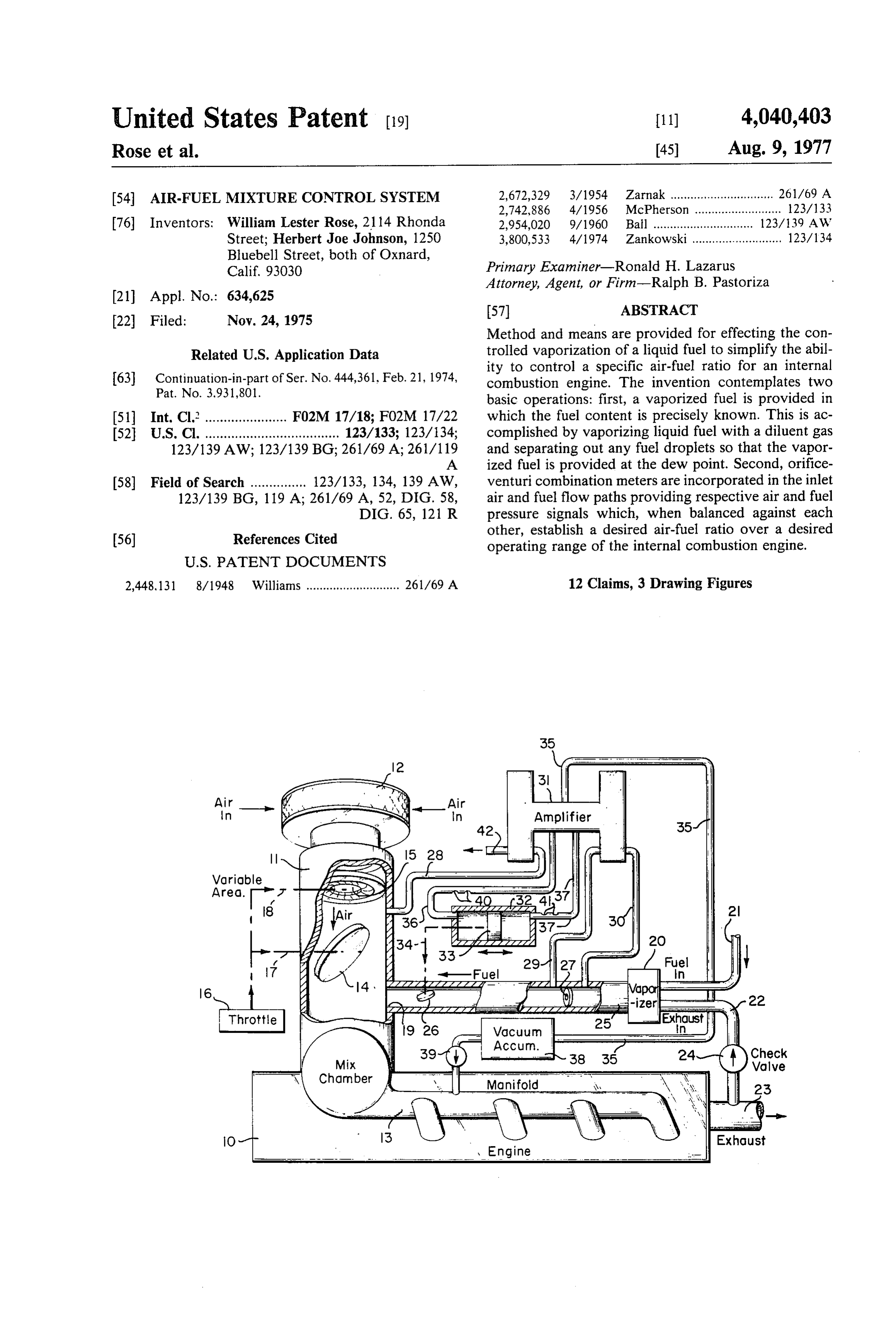
United States Patent (19) 11) 4,040,403 Rose et al. (45) Aug. 9, 1977 54 AIR-FUELMIXTURE CONTROL SYSTEM 2,672,329 3/1954 Zarnak ............................... 261/69 A 2,742,886 4/1956 McPherson .......................... 123/133 76) Inventors: William Lester Rose, 2114 Rhonda 2,954,020 9/1960 Ball ................ ... 123/139 AW Street; Herbert Joe Johnson, 1250 3,800,533 4/1974 Zankowski ........................... 123/134 Bluebell Street, both of Oxnard,
Calif. 93.030 Primary Examiner-Ronald H. Lazarus
Attorney, Agent, or Firm-Ralph B. Pastoriza
Method and means are provided for effecting the con
Related U.S. Application Data trolled vaporization of a liquid fuel to simplify the abil Continuation-in-part of Ser. No. 444,361, Feb. 21, 1974, ity to control a specific air-fuel ratio for an internal 63 combustion engine. The invention contemplates two Pat. No. 3.931,801. basic operations: first, a vaporized fuel is provided in 51 Int. Cl. ...................... F02M 17/18; F02M 17/22 which the fuel content is precisely known. This is ac 52 U.S. Cl. .................................... 123/133; 123/134; complished by vaporizing liquid fuel with a diluent gas 123/139 AW; 123/139BG; 261/69 A; 261/119 and separating out any fuel droplets so that the vapor A ized fuel is provided at the dew point. Second, orifice 58) Field of Search ............... 123/133, 134, 139 AW, venturi combination meters are incorporated in the inlet 123/139 BG, 119 A; 261/69 A, 52, DIG. 58, air and fuel flow paths providing respective air and fuel DIG. 65, 121 R pressure signals which, when balanced against each
References Cited other, establish a desired air-fuel ratio over a desired (56) operating range of the internal combustion engine.
2,448, 131 8/1948 Williams ............................ 261/69 A 12 Claims, 3 Drawing Figures
gasy fast, aaZZZZZZZZZZ as
ZZZZZYZZZ
Vacuum
ACCurn.
Page 2
Drawing sheet — no readable text.
Page 3
near the preferred levels for best economy and effi
ARFUELMIXTURE CONTROL SYSTEM ciency. Thus, it is apparent that the air-to-fuel ratio must be controlled as a function of load and speed for opti
This applicaton is a continuation-in-part of our co mum economy and efficiency.
pending patent application, Ser. No. 444,361 filed Feb. The foregoing provision of lean air-to-fuel ratios in 21, 1974, now U.S. Pat. No. 3,931,801 and entitled combination with a homogeneous mixture of dry fuel FUEL VAPORIZER AND CONTROL SYSTEM. vapor and air reduce flame propagation speeds and This invention is directed to a method and means for allows the use of high compression and minimum spark effecting the controlled vaporizing of a liquid fuel and together with the best torque spark advance which controlling the flow rate of the fuel relative to the inlet O results in a substantially improved fuel consumption air flow rate to provide a desired air-to-fuel mixture for coupled with much improved emissions. an internal combustion engine. In providing a proper system for controlling the air
BACKGROUND OF THE INVENTION
to-fuel ratio, it is necessary that one know the exact percentage of fuel in the vaporized fuel mixed with the
Any new carburetion system for an internal combus 15 incoming air. The problem involved is not in being able tion engine to be useful at all, must perform at least as to vaporize a sufficient quantity of fuel, but rather that well as known devices in the areas of fuel economy and of controlling the vaporization such that the amount of exhaust emission. As will become evident, both econ fuel vaporized can be determined and thus held con ony and exhaust emissions are heavily dependent upon stant. The achievement of a dew point of a vapor and a predetermined air-to-fuel ratios. 20 diluent is an excellent method of attaining such a con It is generally accepted in the field that reduction of trol. If a mixture of fuel vapor and diluent is at dew harmful emissions could be accomplished by delivering point and the temperature of the mixture is known, the a homogeneous mixture of air and fuel to the engine percentage of a given vapor to diluent is known. thereby allowing lean mixtures to be burned with com There have been many means devised and patented plete combustion. Known state-of-the-art carburetion 25 for vaporizing fuel, but none is known to control vapor induction devices utilized with the conventional inter ization by assuring the achievement of a dew point prior nal combustion engine are capable of providing com to our invention as set forth in the heretofore referred to plete combustion with air-to-fuel ratios of 18.5:1. Air to copending patent application. Without such a control, fuel ratios in this range are effective in reducing hydro except where the fuel is predetermined prior to vapor carbons and carbon monoxide but do little to effectively 30 ization, it is next to impossible to precisely control the reduce oxides of nitrogen. air-to-fuel ratio so essential to low exhaust pollutents If the air-to-fuel ratio were further increased to re and improved economy.
duce oxides of nitrogen the lean limit is reached. This BRIEF DESCRIPTION OF THE PRESENT limit occurs when the air-to-fuel mixture in a cylinder INVENTION can no longer support complete combustion. The result 35 is a sharp increase in the emission of hydrocarbons. Bearing all of the foregoing in mind, the present in Although it is little known, it has been possible for vention contemplates a method and means for automati applicants to achieve air-to-fuel ratios of 21:1 using a cally controlling the fuel-to-air mixture or ratio for an homogeneous mixture of dry fuel vapor and air without internal combustion engine over a desired operating reaching the lean limit. This high air-to-fuel ratio results range of the order of 21:1 to the end that optimum in drastic reductions of oxides of nitrogen while main efficiency results with minimum pollutents in the ex taining low hydrocarbon and carbon monoxide levels. haust.
It should be recognized that the above discussion In the even the precise percentage of fuel passed for applies at relatively high power settings for the engine. mixture with incoming air is not known or not initially For example, an RPM greater than 60% of maximum 45 controlled, the invention also contemplates in combina torque RPM and power at a given RPM greater than tion with the fuel to air ratio control system, a method 30% of maximum torque RPM. At lower power and and means for providing a controlled fuel vapor RPM, the lean limit decreases reaching a minimum of wherein the percentage of fuel is precisely known and about 16:1 air-to-fuel ratio at idle and increasing with can be held constant. Essentially, the provision of a increasing power and RPM to the 21:1 discussed above 50 controlled vaporized fuel is carried out as described in at highway level road loads. our heretofore referred to copending patent application In view of the foregoing, it is not only necessary for wherein liquid fuel is mixed with a diluent such as the a system to be susceptible to tight control of the air-to exhaust gas of the internal combustion engine to vapor fuel ratio, but it must also have the flexibility to allow a ize the fuel, droplets being separated out from the va change in the air-to-fuel ratio which changes with 55 porized fuel so that it passes along a given direction at changing load conditions. If the system does not have dew point.
this flexibility but does have the ability to maintain a With respect to the control of the air-to-fuel ratio, constant air-to-fuel ratio, it would only really be effec incoming air is passed through an orifice-venturi meter tive over a desired or given operating range and would combination to result in air pressure signals with varia not function well outside such range. 60 tions in the air flow per unit time. The fuel vapor at dew Theoretically, the higher the air-to-fuel ratio, the point in turn is passed through an orifice-venturi meter more thermally efficient an engine will perform. This combination to result in fuel pressure signals with varia theory is generally true for the higher power levels tions in the fuel flow per unit time. The air pressure discussed above. Under lighter loads and speeds such as signal is then balanced against the fuel pressure signal idle and low speed cruise, thermal losses and low com 65 when a desired air-to-fuel flow is established to thereby pression levels of the fuel change resulting in reduced maintain the air-to-fuel ratio constant. efficiencies with increasing air-to-fuel ratio. The pre A further variation of the air orifice-venturi meter ferred air-to-fuel ratios for reduced emissions are very combination can be effected in accord with this inven
Page 4
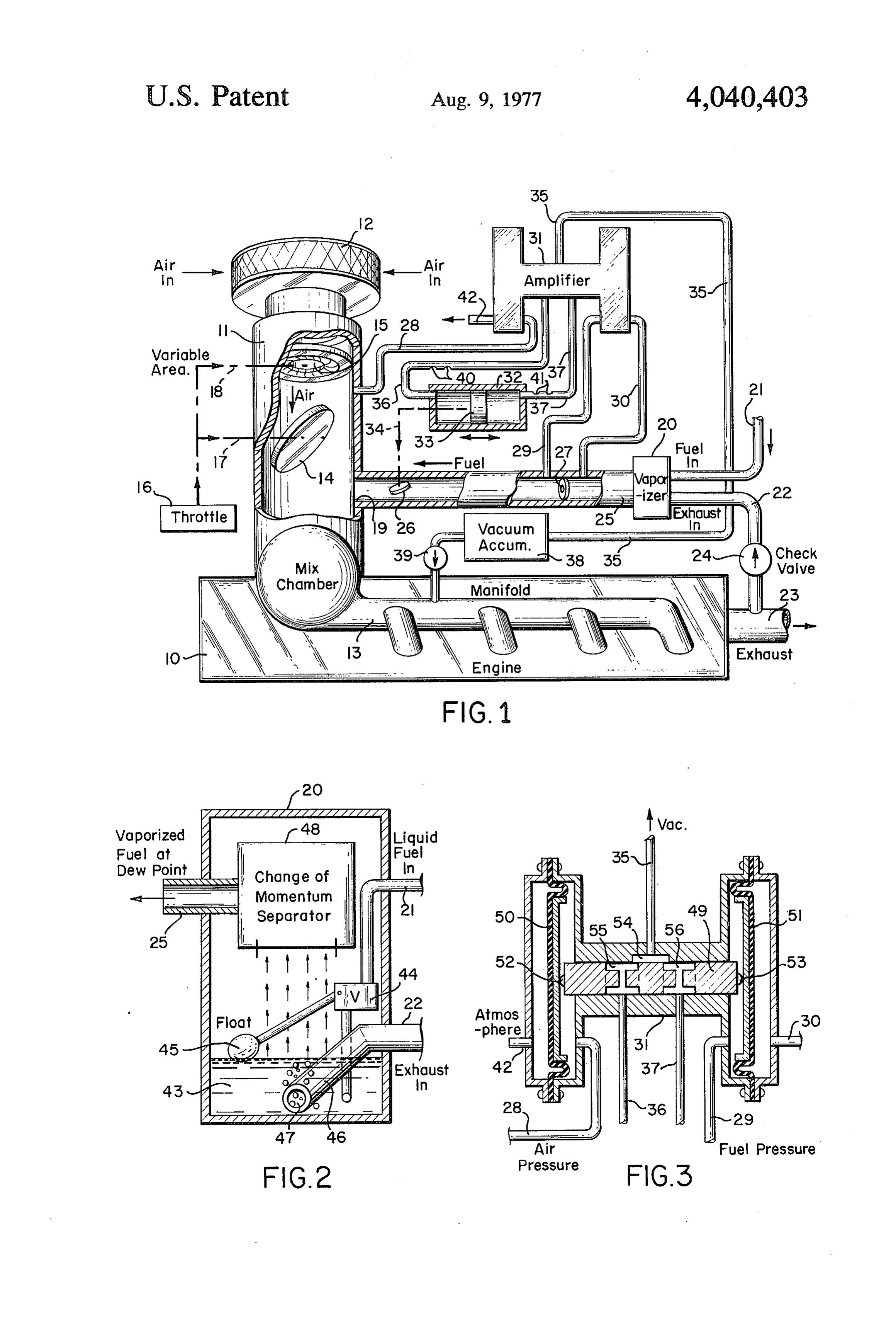
tion to change the pressure signals with changes in the cludes a liquid fuel inlet 21, an exhaust gas inlet 22 flow rates so that the air-to-fuel ratio can be changed which may be piped from the exhaust outlet 23 for the from a constant value for various conditions outside the engine 10 through a check valve 24, and a fuel vapor desired operating range to provide optimum engine outlet or line 25.
efficiency. 5 A fuel valve 26 including an orifice-venturi meter
BRIEF DESCRIPTION OF THE DRAWINGS
combination 27 is incorporated in the fuel outlet line 25 as shown in the broken away portions.
A better understanding of the method and apparatus The ratio of air to fuel vapor is precisely controlled in of this invention will be had by referring to the accom accord with this invention by utilizing the pressure panying drawings in which: 10 outputs of the orifice-venturi meter combinations in the FIG. 1 is a diagrammatic showing only of an internal respective air inlet and fuel vapor lines. Towards this combustion engine in which the fuel vaporizer and end, there is provided a small conduit 28 from the pipe fuel-to-air ratio control system of this invention have section 11 downstream of the variable orifice 15 in the been incorporated; air inlet providing an air pressure signal in accordance FIG. 2 is an enlarged view partly in cross section of 15 with the setting of the inlet valve means. Similarly, the vaporizer unit of FIG. 1; and, there is provided a small conduit 29 and return conduit FIG. 3 is an enlarged fragmentary cross section of an 30 on either side of the orifice 27 providing a fuel pres amplifier portion of the fuel-to-air ratio control system sure signal in accordance with the setting of the fuel in FIG. 1. valve. The areas or openings of the respective orifices in 20 the air inlet valve orifice-venturi meter and fuel valve
DETAILED DESCRIPTION OF THE orifice-venturi meter are sized such as to equalize this INVENTION air pressure signal and fuel pressure signal when a de The essence of the method of the present invention sired air-to-fuel ratio is established. Thus, by controlling for maintaining a desired ratio of air-to-fuel mixture for one or the other of the valves in a manner to maintain an internal combustion engine includes the steps of: 25 the air pressure signal equal to or balanced against the first, providing fuel in a vaporized state wherein the fuel pressure signal, a constant air-to-fuel ratio will be percentage of fuel is precisely known; second, passing maintained over a desired operating range. the vaporized fuel along a direction to mix with incom The foregoing control is accomplished by pressure ing air; third, generating an air signal constituting a differential responsive means receiving the air pressure function of air flow per unit time; fourth, generating a 30 signal and fuel pressure signal and connected to the fuel fuel signal constituting a function of fuel flow per unit valve to automatically change the setting of the fuel time; and fifth, controlling the fuel flow per unit time valve whenever a pressure differential exists between along said direction in accordance with a given relation the air pressure signal and fuel pressure signal to ship between the generated signals to thereby maintain thereby change the flow rate of fuel in a direction to a desired ratio of air-to-fuel mixture for use in the inter 35 equalize the air pressure signal and fuel pressure signal. nal combustion engine. Thus, as shown in FIG. 1 the air pressure signal in As mentioned heretofore, if the percentage of fuel is conduit 28 and fuel pressure signal in conduit 29 pass to not precisely known, it is next to impossible to control an amplifier 31 which functions to amplify any pressure the air-to-fuel mixture. Thus, where a liquid fuel is used difference and apply the same to opposite ends of a as in a conventional gasoline internal combustion en cylinder 32 containing a double acting piston 33 con gine, the method of this invention also contemplates nected to the fuel valve 26 as indicated by the dashed mixing the vaporized fuel with a diluent gas such that line 34.
the diluent is saturated with fuel vapor thereby provid As will become clearer as the description proceeds, ing fuel vapor at the dew point so that effectively, the the amplifier 31 includes a slide valve having an inlet percentage of fuel in the diluent is known and is main 45 connected to a source of vacuum by means of a line 35, tained constant. and first and second outlets 36 and 37 connecting to the Referring now specifically to FIG. 1 there is shown opposite sides of the cylinder 32 as shown. In the partic apparatus for carrying out the foregoing method with ular embodiment shown, the vacuum source for the respect to a conventional internal combustion engine. In inlet line 35 is derived from the engine manifold 13 to a this respect, the engine is diagramatically indicated at 50 vacuum accumulator 38 and check valve 39. 10. In accord with the invention, a pipe section 11 is In order that the proper fuel valve position be main arranged to be inserted between the air intake 12 and tained by the double acting piston under rapid pressure the input manifold 13 of the engine 10. As shown in the changes during rapid changes in inlet air flow, there are broken away portion, the pipe section 11 incorporates provided small bleeder openings such as indicated at 40 an inlet air valve means in the form of a butterfly valve 55 and 41 in the outlet lines 36 and 37 passing into the 14 and including a orifice-venturi meter combination 15. opposite ends of the cylinder 32 for the double acting The orifice portion of this combination 15 is variable in piston 33. As will be subsequently described, the ampli size similar to the iris of a camera lens. As indicated by fier 31 includes diaphragm means balancing the air pres the dot-dashed lines, the butterfly valve 14 is operated sure signal against the fuel pressure signal, the air pres to various set positions by the throttle schematically 60 sure signal in line 28 acting on one side of the dia indicated by the block 16. Also, as indicated by the phragm, the other side being open to atmosphere as by dashed-dot line 18, the size of the variable orifice in the outlet 42, the fuel pressure signal in line 29 also acting orifice-venturi combination 15 is controlled by the on the diaphragm means in an opposite sense the other throttle 16. side connecting to the return line 30. Downstream of the air inlet valve means in the pipe 65 Referring now to FIG. 2, details of the vaporizer unit section 11 is a fuel vapor inlet 19 for passing fuel at dew 20 described in FIG. 1 for providing fuel vapor at dew point from a vaporizer unit 20 shown as a block in the point in the line 25 are shown. Thus, the unit 20 com right central portion of FIG. 1. Fuel vaporizer 20 in prises a closed chamber receiving the liquid fuel inlet
Page 5
line 21 providing a reservoir of liquid fuel as indicated its new setting. It will be recalled that so long as these at 43. A level responsive means in the form of a float pressures are exactly balanced against each other, a valve 44 with associated float 45 maintains the level of constant air-to-fuel ratio is maintained. the liquid fuel 43 at a given level so that incoming ex OPERATION haust gas in the exhaust inlet 22 can be bubbled up through the liquid fuel 43 and vaporize the same. This In operation, it will be understood that the mass rate bubbling action is accomplished by an exhaust pipe of flow of a fluid across the orifice-venturi meter combi connecting means 46 passing through a portion of the nation of the types utilized in the air inlet and fuel line chamber and thence extending into the liquid fuel 43 to of FIG. 1 is a function of the discharge coefficient the terminate beneath the surface of the liquid fuel. The O meter, the area or size of the orifice, the density of the terminal end of the connecting means 46 has a plurality air or fuel as the case may be, and the pressure drop of small outlet openings 47 so that exhaust gases can across the meter.
only escape into the chamber by bubbling up through For a given design of meter, the discharge coefficient the liquid fuel. and orifice size or area remain constant. Therefore, the A separating means shown by the block 48 functions 15 pressure drop across the meter is a function of the mass to remove any droplets from the fuel in such a manner rate of flow through the meter and the density of the that vaporized fuel at dew point passes through the fuel fluid flowing. Since the density of either the air or fuel outlet line 25. The separator 48 may be a change of is known, the mass rate of flow can be determined if the momentum separator in which the vaporized fuel is pressure drop is known.
caused to swirl about a curved path or may incorporate 20 From the foregoing, it will be evident that two differ baffles to cause the fuel to traverse a path which ent mass rates of flow can be measured by two different changes directions. designed meters where both meters have identical pres The structure described FIG. 2 is similar to that in our sure drops by simply making the size or area of one of copending patent application for providing supersatu the meters different from that of the other. It will also rated fuel vapor or fuel vapor at the dew point. As 25 be seen that the ratio between the two rates of flow mentioned heretofore, it is vitally important in order measured by two meters remains constant regardless of that a precise control of air-to-fuel ratio be realized that the particular flow rates. Therefore, by proper attention the exact amount of fuel in the fuel vapor be known. By to the size or areas of the orifices, two meters can be thus providing fuel at dew point, the quantity of fuel is built wherein one measures fuel and one air, such that constant. In furtherance of quantisizing the fuel, the 30 whenever the pressure drop of the two meters is equal, liquid fuel temperature is held substantially constant a constant air-to-fuel ratio is attained. Moreover, it is prior to mixing with the exhaust gas or diluent gas. No possible to vary the air-to-fuel ratio in accordance with problem is encountered in this respect since most inter the rate of flow by varying the area or size of one of the nal combustion engines are water cooled and the tem orifices with variations in rate of flow. perature of the engine and the liquid fuel remains at a 35 Accordingly, if it is desired for the engine of FIG. 1 to given value. Similarly, the incoming diluent or exhaust maintain an air-to-fuel ratio of, for example, 21:1, the gas in the line 22 will be substantially constant and is so orifice 15 in the air inlet valve means and the orifice 27 maintained. in the fuel valve are sized relatively to each other to Referring now to FIG. 3, details of the amplifier 31 establish this ratio when the pressure drops as detected described in FIG. 1 are shown. Thus, the slide valve by the pressure signals in the conduits 28 and 29 respec heretofore referred to is indicated at 49 and is arranged tively are equal.
to be urged in a left or right direction as viewed in FIG. With the foregoing criteria established, it will now be 3 by diaphragm means 50 and 51 engaging opposite evident that when the air inlet flow is increased as by sides of the slide valve as at 52 and 53. The incoming operating the throttle 16 to vary the valve 14, the in Vacuum line communicates with a passage 54 which in 45 creased drop in the air pressure signal will be conducted turn overlaps passages 55 and 56 in the slide valve 49 by conduit 28 directly to the amplifier 31 thereby caus when the same is in a centered position. Vacuum is thus ing the slide valve to move to the right as viewed in applied equally to the lines 36 and 37 connecting to the FIG. 3 and thus apply more vacuum to the line 36 and outlets of the amplifier 31. less vacuum to the line 37. With greater vacuum on the It will be appreciated that the slide valve 49 is main 50 line 36 than in line 37, the double acting piston 33 will tained in a center position when the pressure applied move to the left as viewed in FIG. 1 and open the fuel against the diaphragm 50 from the air pressure signal valve 26 to a greater extent to thereby re-establish the conduit 28 exactly balances the pressure applied across desired air-to-fuel ratio.
the diaphragm 51 from the fuel pressure signal in the Similarly, when the air inlet valve is closed down conduit 29. However, should there exist a differential in 55 there will be an effective increase in the air pressure these pressures, the slide valve 49 will move in one signal in conduit 28 which will move the diaphragm direction or the other to apply more vacuum to one of means 50 illustrated in FIG. 3 to the left to provide the other of the lines 36 and 37, the passage 54 overlap more vacuum in the outlet line 37 than in the outlet line ping to a greater extent one of the passages 55 or 56 than 36. The double acting piston 33 of FIG. 1 will thus the other. 60 move to the right and correspondingly close down the As described in FIG. 1, the amplified differential fuel valve 26 thereby changing the fuel pressure signal pressures are applied to the double acting piston 33 to in conduit 29 until balance is re-established between the move this piston in one direction or the other and thus air pressure and fuel pressure signals. Thus again the change the setting of the fuel valve 26 in a direction to desired air-to-fuel ratio is maintained. again equalize the air pressure and fuel pressure signals 65 It will be appreciated from the foregoing that a con in the conduits 28 and 29 applied to the amlifier. The stant air-to-fuel ratio can be maintained over a desired double acting piston 33 will thus be maintained in its operating range of the engine. However, in those in moved position and the fuel valve will be maintained at stances where the engine is idling or running extremely
Page 6
slowly outside the normal desired range at highway 4. A fuel vaporizer and control system comprising, in speeds, optimum efficiency of the engine results with a combination:
lower air-to-fuel ratio all as described heretofore. For a. a pipe section arranged to be inserted between the these latter contitions outside the desired operating air intake and input manifold of an internal combus range, the actual area or size of the orifice 15 in the air tion engine, said pipe section including an air inlet intake can be automatically changed by the mechanical valve means for controlling inlet air flow and a fuel connection 18 to the throttle 16 so that when the throt vapor inlet, said air inlet valve means including an tle 16 is closed, this action will come into play to change orifice-venturi meter combination providing an air the effective area or size of the orifice and thus establish pressure signal in accordance with the setting of the a new air-to-fuel ratio when the air pressure signal is O inlet valve means;
balanced against the fuel pressure signal. Of course, b. a vaporizer unit including a closed chamber having when the RPM of the engine is increased to the desired a liquid fuel inlet connected to receive liquid fuel operating range, then the area of the orifice 15 is main for said engine, an exhaust gas inlet connected to tained constant. receive exhaust gases from said engine, and a fuel The term "orifice-venturi meter combination' as used 15 vapor outlet;
herein and in the appended claims is understood to c. a liquid fuel reservoir in said chamber, cover either a single orifice or a single venturi section or d. level responsive means within said chamber to a combination of both. maintain the level of liquid fuel in said chamber at a From the foregoing description, it will be evident that given level;
the present invention has provided not only a unique e, exhaust pipe connecting means passing from said means for providing fuel in which the fuel density or exhaust gas inlet through a portion of said chamber content is precisely known but wherein as a conse and thence extending into said liquid fuel to termi quence, it is possible to precisely control the air-to-fuel nate beneath the surface of said liquid fuel, the ter ratio supplied to the engine all to the end that vastly minal end of said connecting means beneath said improved engine operation is achieved and pollutents in 25 liquid level including outlet means so that exhaust the exhaust are minimized. gases can only escape into said chamber by bub What is claimed is: bling up through said liquid fuel; 1. A method of vaporizing fuel and maintaining a f. separating means in said chamber, said fuel vapor desired ratio of air to fuel mixture in an internal combus 30 outlet passing from said chamber at a point follow tion engine including the steps of: ing the separating means and connecting into said a. holding the temperature of a liquid fuel and a dilu fuel vapor inlet in said pipe section; ent gas substantially constant prior to mixing: g. a fuel valve for controlling the flow of vaporized b. mixing said diluent gas with said liquid fuel such fuel into said fuel vapor inlet, said fuel valve includ that an excess of fuel is provided to super saturate 35 ing an orifice-venturi meter combination providing the gas with fuel; a fuel pressure signal in accordance with the setting c. separating out fuel droplets from the super satu of said fuel valve, the areas of the respective orifices rated gas by passing the mixture of diluent gas and in the air inlet valve orifice-venturi meter and fuel liquid fuel through a change of momentum separa valve orifice-venturi meter being sized such as to tor to provide gas saturated with vaporized fuel equalize said air pressure signal and fuel pressure resulting in fuel vapor at the dew point; signal when a desired air-to-fuel ratio is established; d. passing the fuel vapor at dew point along a direc and, tion to mix with incoming air; h. control means conected to said air inlet valve e. generating an air signal constituting a function of
means and fuel valve responsive to the relative f generating a fuel signal constituting a function of flows of air and fuel respectively therethrough to the fuel flow per unit time while in the vaporized maintain a desired ratio of air to fuel whereby hot state; and exhaust gases pass through the exhaust pipe con g. controlling the fuel flow per unit time along said necting means and bubble through the liquid fuel to direction in accordance with a given relationship 50 vaporize the same, the vaporized fuel passing between the generated signals to thereby maintain a through the separating means to thereby remove desired ratio of air-to-fuel mixture in said internal any liquid droplets not vaporized so that substan combustion engine. tially only vaporized fuel at dew point passes 2. The method of claim 1, in which said diluent gas is through said fuel valve into said fuel inlet in said taken from the exhaust of said internal combustion en 55 pipe section to then mix with air passing through gine. said air inlet valve means and provide an explosive 3. The method of claim 1, in which said generated air and fuel mixture at said desired ratio for said signals are pressure signals provided by: engine, said control means including a pressure a. passing the incoming air flow through a venturi-ori differential responsive means receiving said air fice meter combination to result in air pressure 60 pressure signal and fuel pressure signal connected variations with variations in the air flow per unit to said fuel valve to automatically change the set time; ting of said fuel valve whenever a pressure differen b. passing the fuel through a venturi-orifice meter tial exists between said air pressure signal and said combination to result in fuel pressure variations fuel pressure signal to change the flow rate of fuel with variations in the fuel flow per unit time; and 65 in a direction to equalize said air pressure signal and c. balancing the air pressure signal against the fuel fuel pressure signal whereby the established air-to pressure signal when a desired air-to-fuel flow is fuel ratio is maintained over a desired operating established. range of said internal combustion engine.
Page 7
5. A system according to claim 4, in which said ex to-fuel ratio is established; differential responsive means haust inlet to said vaporizer includes a check valve to receiving said air pressure signal and fuel pressure signal block reverse flow of gases from said chamber. connected to said fuel valve to automatically change the 6. The subject matter of claim 4, in which said pres setting of said fuel valve whenever a pressure differen sure differential responsive means includes a cylinder tial exists between said air pressure signal and fuel pres having a double acting piston connected to said fuel sure signal to change the flow rate of fuel in a direction valve for changing the setting of said fuel valve in one to equalize said air pressure signal and fuel pressure direction or the other in response to movement of said signal whereby the established air-to-fuel ratio is main piston in said cylinder in one direction or the other; and tained over a desired operating range of said internal an amplifier means including a slide valve having an 10 combustion engine, the orifice in said orifice-venturi inlet and first and second outlets, said inlet being con meter combination in said air inlet valve means being nected to a source of vacuum and said outlets being variable in size; and means coupled to said orifice and connected respectively to opposite ends of said cylin responsive to said air flow such that the air to fuel ratio der, movement of said slide valve from a center position is automatically changed for certain settings of said inlet increasing the vacuum applied to one outlet and de 15 valve means.
creasing the vacuum applied to the other outlet, said 10. The subject matter of claim 9 in which said pres amplifier further including pressure responsive dia sure differential responsive means includes a cylinder phragm means positioned to engage said slide valve and having a double acting piston connected to said fuel having inlet passages on opposite sides connected re valve for changing the setting of said fuel valve in one spectively to receive said air pressure signal and fuel 20 direction or the other in response to movement of said pressure signal whereby movement of the slide valve as piston in said cylinder in one direction or the other; and a result of a differential pressure across said diaphragm an amplifier means including a slide valve having an means applies an amplified differential pressure across inlet and first and second outlets, said inlet being con said double acting piston in said cylinder. nected to a source of vacuum and said outlets being 7. The subject matter of claim 6, including a vacuum 25 connected respectively to opposite ends of said cylin accumulating chamber connected between the manifold der, movement of said slide valve from a center position of said internal combustion engine and the inlet of said increasing the vacuum applied to one outlet and de slide valve to provide said source of vacuum. creasing the vacuum applied to the other outlet, said 8. The subject matter of claim 6, in which small amplifier further including pressure responsive dia bleeder holes are provided in the connection between 30 phragm means engaging said slide valve and having said outlet and opposite ends of said cylinder for said inlet passages on opposite sides connected respectively double acting piston to permit the proper fuel valve to receive said air pressure signal and fuel pressure position to be maintained by said double acting piston signal whereby movement of the slide valve as a result under rapid pressure changes during rapid changes in of a differential pressure across said diaphragm means inlet air flow. 35 applies an amplified differential pressure across said 9. An air-fuel mixture control system for an internal double acting piston in said cylinder. combustion engine including, in combination, an air 11. The subject matter of claim 10, including a vac inlet valve means for controlling inlet air flow per unit uum accumulating chamber connected between the time and including an orifice-venturi meter combination manifold of said internal combustion engine and the providing an air pressure signal in accordance with the inlet of said slide valve to provide said source of vac Setting of the air inlet valve means; a fuel valve for U.
controlling fuel flow per unit time and including an 12. The subject matter of claim 10, in which small orifice-venturi meter combination providing a fuel pres bleeder holes are provided in the connection between sure signal in accordance with the setting of said fuel said outlets and ends of said cylinder for said double valve, the areas of the respective orifices in the air inlet 45 acting piston to permit the proper fuel valve position to valve orifice-venturi meter and fuel valve orifice-ven be maintained during rapid pressure changes as a result turi meter being sized such as to equalize said air pres of rapid changes in inlet air flow. Sure signal and fuel pressure signal when a desired air k k is xk sk
Provenance
- Collection
- Cited prior art
- Original PDF
- patentimages.storage.googleapis.com →
- Filed
- 1975-11-24
- Pages
- 7
- Method
- pdftotext (the PDF's own text layer) + pdftoppm 300dpi page scans
- Source
- Google Patents bibliographic record
- Granted
- 1977-08-09
- Inventors
- William Lester Rose; Herbert Joe Johnson
- Transcribed from
- patentimages.storage.googleapis.com →