patent · US4274383
Fuel vaporizer
23 June 1981
Page 1 — bibliographic record
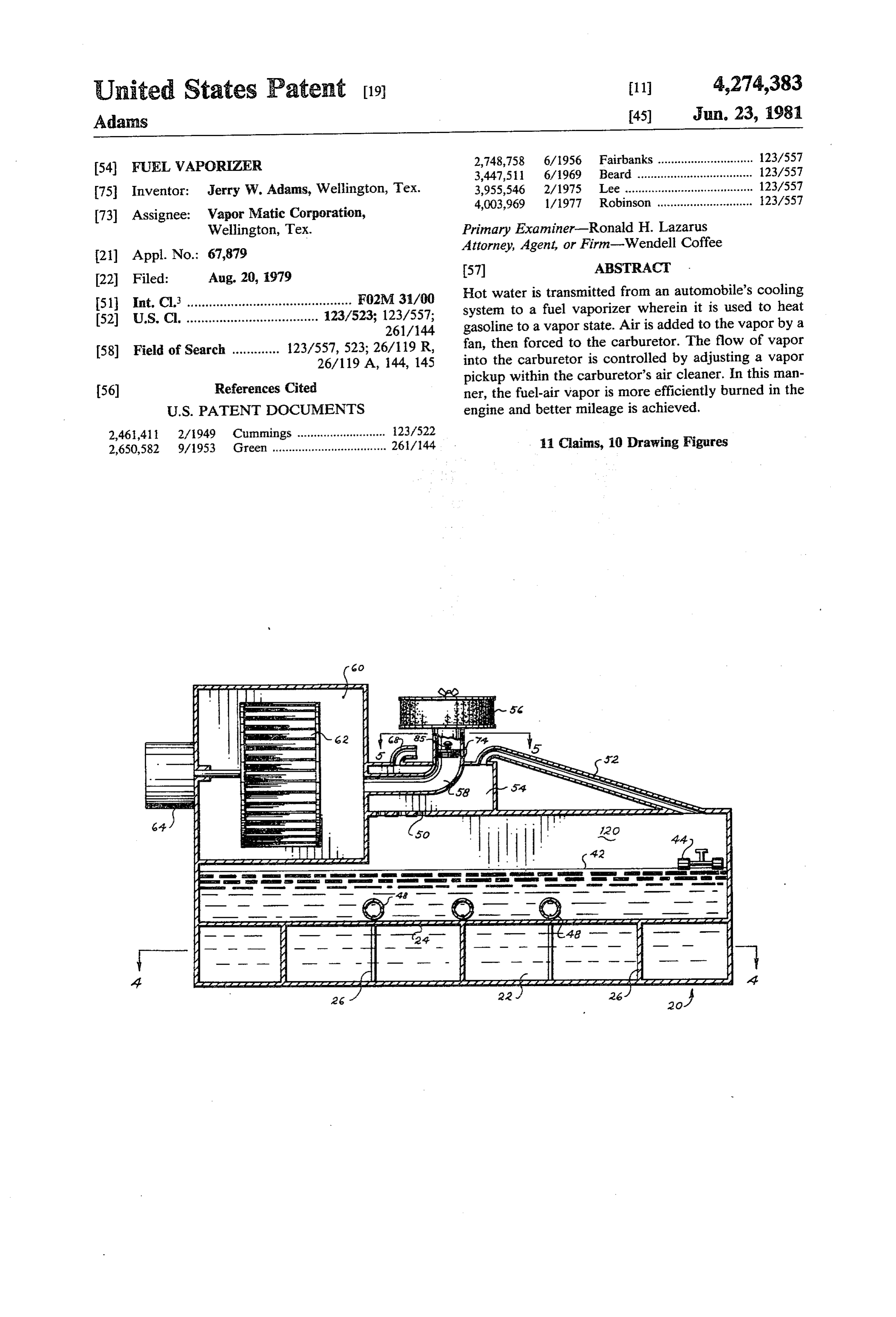
United States Patent (19) 11 4,274,383 Adams 45) Jun. 23, 1981 (54) FUEL VAPORIZER 2,748,758 6/1956 Fairbanks ............................. 123/557 3,447,511 6/1969 Beard ................................... 123/557 75 Inventor: Jerry W. Adams, Wellington, Tex. 3,955,546 2/1975 Lee ....................................... 123/557 73) Assignee: Vapor Matic Corporation, 4,003,969 1/1977 Robinson ............................. 123/557 Wellington, Tex. Primary Examiner-Ronald H. Lazarus 21) Appl. No.: 67,879 Attorney, Agent, or Firm-Wendell Coffee 22 Filed: Aug. 20, 1979 57 ABSTRACT 51 Int. Cl. ...... - - - - - - - - - - - - - - - - - A r F02M 3/00 Hot water is transmitted from an automobile's cooling 52) U.S. Cl. .................................... 23/523,123/557
gasolinetotoaa fuel vaporvaporizer state. Airwherein is addedittoistheused to by vapor heata
fan, then forced to the carburetor. The flow of vapor into the carburetor is controlled by adjusting a vapor us pickup within the carburetor's air cleaner. In this man 56) References Cited ner, the fuel-air vapor is more efficiently burned in the
2,650,582 9/1953 Green ................................... 26/44 11 Claims, 10 Drawing Figures
Page 2
Drawing sheet — no readable text.
Page 3
Drawing sheet — no readable text.
Page 4
Drawing sheet — no readable text.
Page 5
s TS:
YaYa YaYSAs
a NYY
als.
XYSAS
A. FIH EHigZyzzzzzzz)E
u) YvaS
174 f 1.
7 ar I-76 ?o %ZZZZ a2%ZZZZZZZZZZZZZZZZZZZZZZZZZZZ 2ZZZZZZZZZZZZZZZZZZZ.4%
SS. || ||
T.I. anN
IIH
Page 6
Drawing sheet — no readable text.
Page 7
reduce the total output of the engine. In view of the fact
FUEL WAPORIZER that automobiles on the road today have engines which generate far more power than is necessary for present
CROSS REFERENCE TO RELATED speed limits, the increase in efficiency greatly out APPLICATIONS weighs the loss of power. I have found that great results None. However, applicant filed Disclosure Docu are achieved when the introduction of the fuel vapor ment No. 079,501 on Apr. 2, 1979, which document can be regulated.
concerns this application; therefore, by separate paper, My system vaporizes fuel at a rate greater than is it is respectfully requested that the document be re 10 necessary to be introduced into the carburetor. The tained. amount of suction which is exerted on the fuel vapor BACKGROUND OF THE INVENTION line is varied by moving a vapor pickup either up or (1) Field of the Invention down in an air pickup tube of the carburetor. In this manner I am able to accurately control the amount of
This invention relates to vaporizing liquid fuels and 15 vapor introduced mixing the vapor with air for spark ignition in an inter into the carburetor and thereby in nal combustion engine. crease the total efficiency of the car's engine. (2) Description of the Prior Art Thus it may be seen that the function of the total Automobiles are powered almost exclusively by in combination far exceeds the sum of the functions of the ternal combustion engines. With the advent of the en float valves, air filters, etc.
ergy shortage, people became concerned with the num (2) Objects of this Invention ber of miles per gallon that their cars could get. Many An object of this invention is to vaporize fuel for an cars on the road today have large engines which can internal combustion engine.
produce much more power than is necessary to go the Another object is to vaporize fuel and thoroughly speed limit. These large engines use a great deal of gas. 25 mix the vapor with air.
Many methods have attempted to increase the gas mile age of these large engines. These attempts to increase theFurther objects are to facilitate adjusting the flow of vapor-air mixture into the carburetor.
the performance of large engines have met with only varying degrees of success. One area for improvement vice that is sturdy,are
Further objects to achieve the above with a de is better vaporization of the liquid fuel. Different meth ple, safe, efficient, compact, versatile, durable, lightweight, sim ecologically compatible, ods for controlling the amount of vapor have been tried. 30
Many inventors have attempted to control the vapor energy conserving, and reliable, yet inexpensive and flow by controlling the amount of fuel which is vapor easy to manufacture, install, adjust, operate and main ized. This method is usually unsatisfactory as it is very tain.
difficult to regulate the rate of vaporization as opposed Other objects are to achieve the above with a method to the rate of introduction of the vapor into the carbure 35 that is versatile, ecologically compatible, energy con tor. serving, rapid, efficient, and inexpensive, and does not Before filing this application, applicant caused a require highly skilled people to install, adjust, operate, search of the prior art to be made at the U.S. Patent and and maintain.
Trademark Office. That search disclosed the following The specific nature of the invention, as well as other patents: objects, uses, and advantages thereof, will clearly ap GRONKWIST-U.S. Pat. No. 1,625,997 pear from the following description and from the ac MENGELKAMP-U.S. Pat. No. 2,821,843 companying drawing, the different views of which are AUTHEMENT-U.S. Pat. No. 3,963,013 not scale drawings.
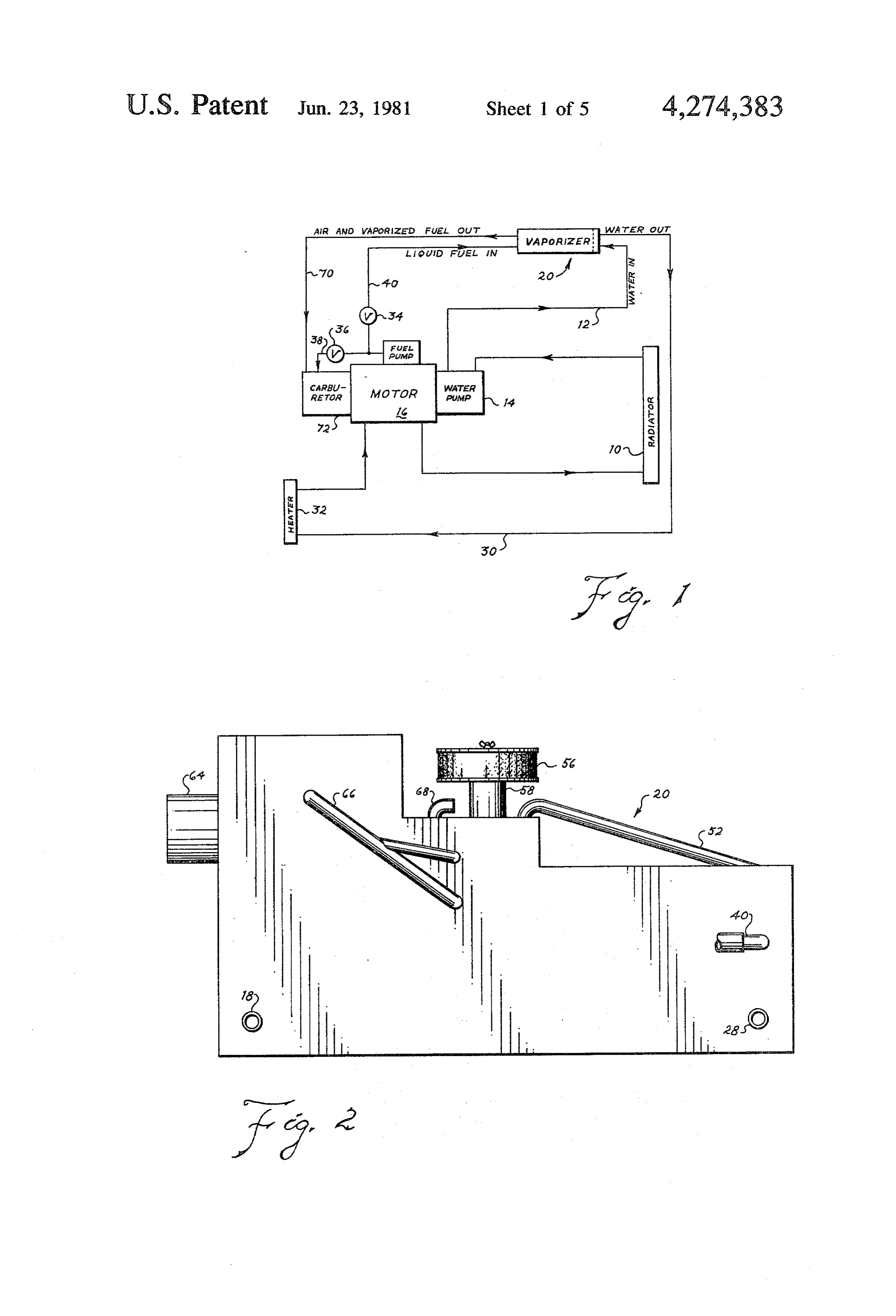
TOTTEN-U.S. Pat. No. 4,106,457 45 BRIEF DESCRIPTION OF THE DRAWING QUINN-U.S. Pat. No. 4,146,002 FIG. 1 is a schematic representation showing the QUINN discloses a fuel preheater using hot water from the car's cooling system to vaporize fuel which is organization of the fuel vaporizer with an automobile mixed with air and forwarded to the carburetor. engine.
TOTTEN discloses a fuel vaporizer for vaporizing 50 FIG. 2 is a side elevational view of a vaporizer ac fuel using hot water and having a valve for adjusting the cording to my invention.
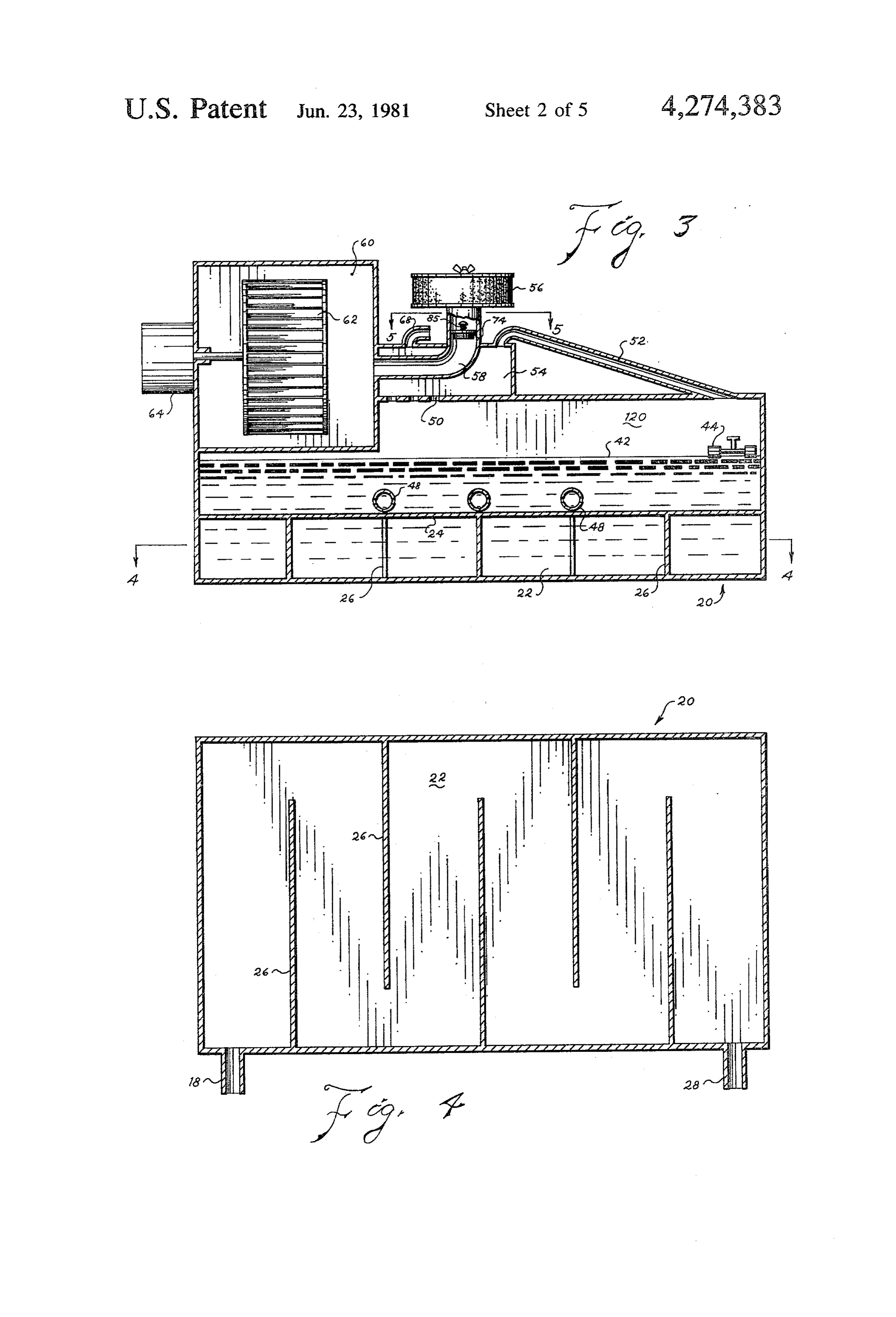
amount of fuel sent into the vaporizer. FIG. 3 is a longitudinal section of the vaporizer gen It appears that the other patents listed are of general erally along line 3-3 of FIG. 7.
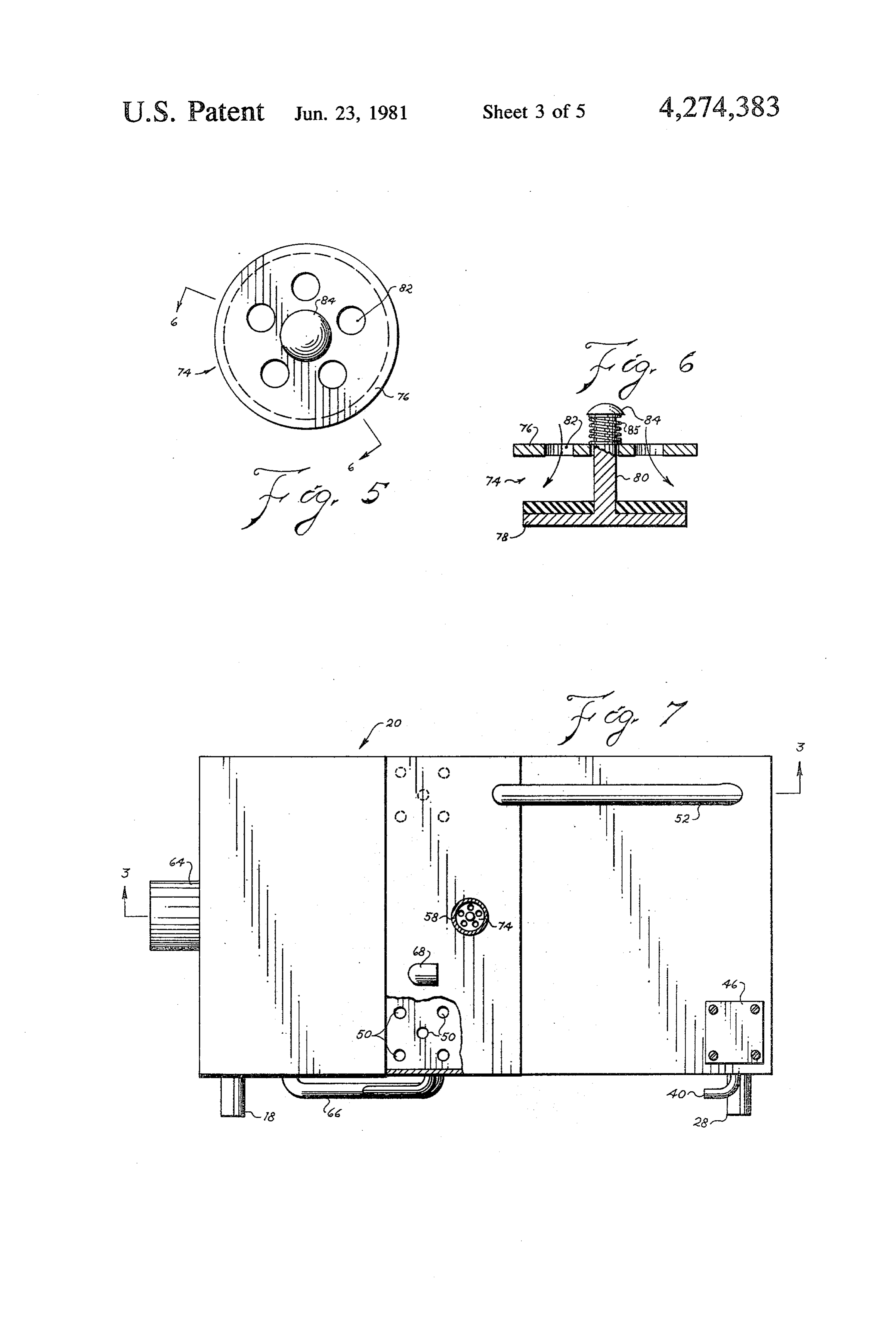
interest only. These prior patents show that the vapori FIG. 4 is a sectional view of the vaporizer taken zation of gas and mixing it with air before it reaches the 55 substantially along line 4-4 of FIG. 3. carburetor increases the gas mileage. However, one of FIG. 5 is a top plan view of the backfire check valve. the most perplexing problems has been the regulation of FIG. 6 is a sectional view of the check valve taken the flow of the vapor into the carburetor. Another substantially along line 6-6 of FIG. 5. problem in the art has been the maintenance of a steady FIG. 7 is a top plan view of the vaporizer. heat in the vapor mixing compartment. 60
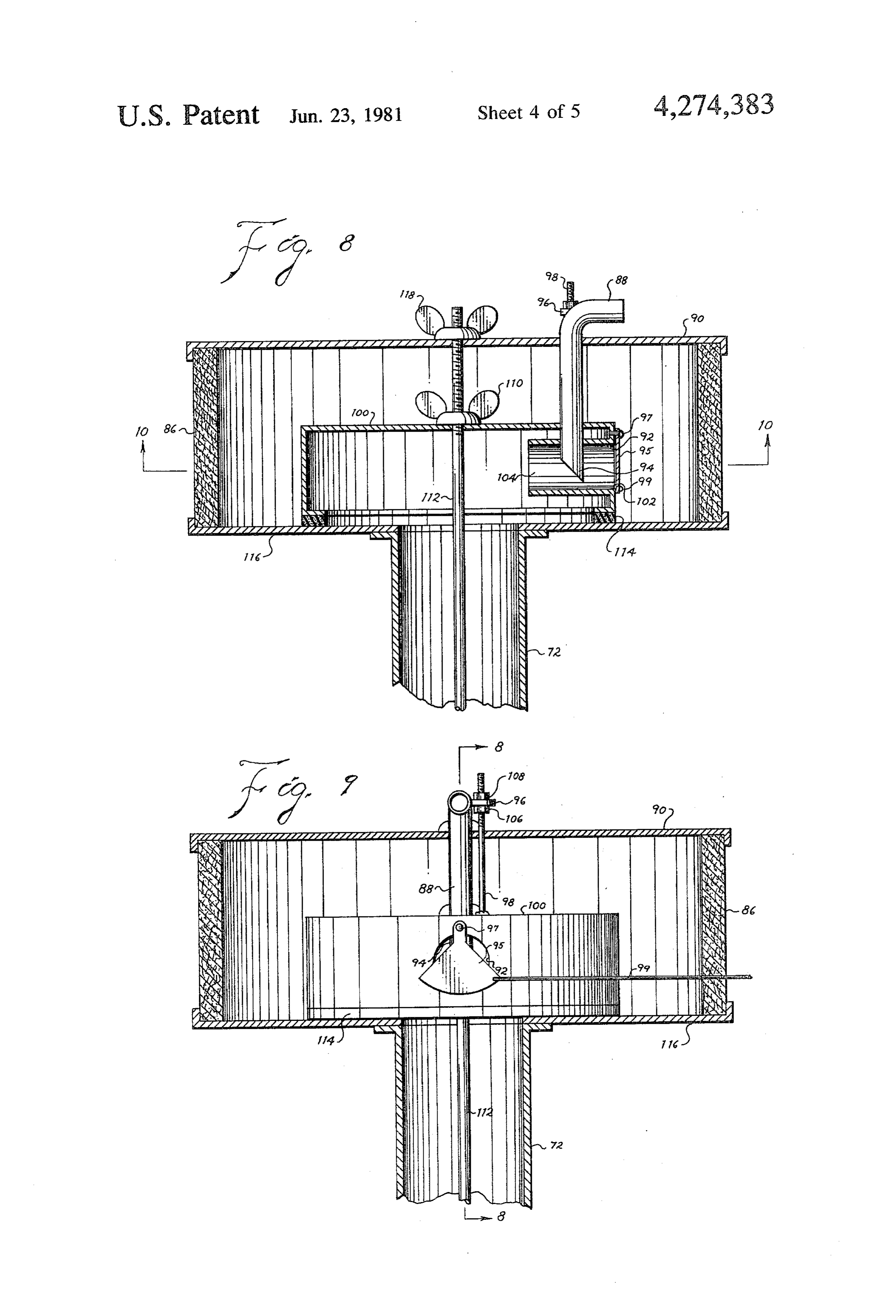
FIG. 8 is a sectional view of an air filter on the engine
SUMMARY OF THE INVENTION carburetor fitted with a fuel-air introduction unit ac (1) New and Different Function cording to my invention taken substantially on line 8-8 I have intended a way to improve the gas mileage of FIG. 9.
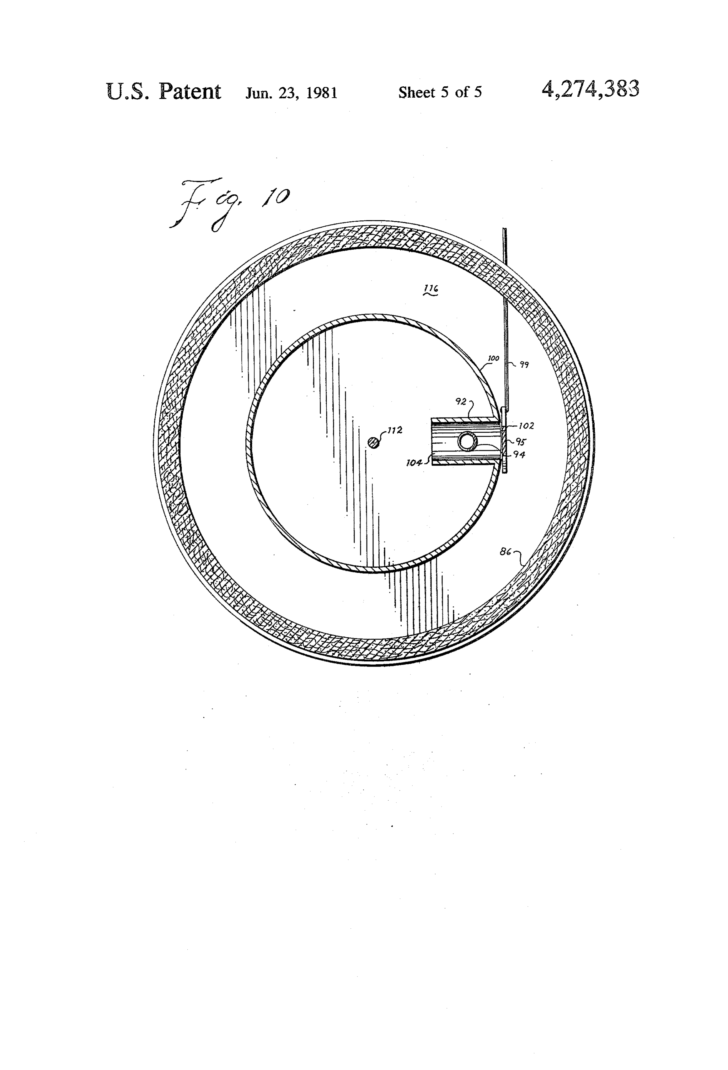
which may be achieved with internal combustion en 65 FIG. 9 is a front elevational view of the fuel-air intro gines. My invention does not increase the power of the duction unit with the air filter shown in section. engine, in fact, it is known that preheating the fuel-air FIG. 10 is a sectional view of the fuel-air introduction vapor before it enters the engine has a tendency to unit taken substantially on line 10-10 of FIG. 8.
Page 8
FIG. 6. This prevents the flow of vapors through the
DESCRIPTION OF THE PREFERRED filter 56 when the engine is stopped. EMBODIMENT Carburetor air filter 86 is fitted for vapor pickup 88. Referring more particularly to FIGS. 1 and 4 of the Vapor line 70 terminates in vapor pickup 88 and it is drawing, hot water is transmitted from the cooling through this pickup that the air-fuel vapor is introduced system on engine or motor 16 (which includes radiator into the carburetor 72. The vapor pickup is an 'L' 10, water pump 14, and heater 32) through hot water shaped tube which extends down through the air filter line 12 to hot water inlet 18 of vaporizer 20. The hot top 90 and at right angles into air pickup tube 92. The water is introduced into hot water compartment 22 of 10 diameter of the vapor pickup 88 is about 1" (2.54 cm) the vaporizer. The top of hot water compartment 22 is ing and its distal end 94 is cut diagonally at 45. An adjust formed by hot plate 24. Baffles 26 are located within the in the ear 96 is attached to the vapor pickup 88 at the bend hot water compartment. The hot water is forced vacuum"L." Adjusting rod 98 extends from the top of chamber 100 through air filter top 90 and through the hot water compartment 22 among baffles through adjusting ear 96. The upper end of the adjust 26 and out through return water outlet 28 back to the 15 ing rod 98 is threaded and the lower end is attached as engine via water return line 30. by welding to the top of the vacuum chamber 100. Air After the car's engine is warm, solenoid valve 34 may is sucked into the carburetor 72 through air pickup tube be electrically opened and solenoid valve 36 closed 92. The air pickup tube 92 is tubular in shape and ex thereby diverting the liquid fuel from fuel line 38 to tends inward in the vacuum chamber toward the carbu vaporizer inlet line 40 into fuel pool 42 in vaporizer 20 retor 72. The diameter of the air pickup 92 is about compartment 120. The valve 34 may be eliminated and twice the diameter of the vapor pickup 88. The air the inlet line 40 always be open. The level of the fuel in pickup 92 has an opening end 102 and terminating end the pool 42 is controlled by fuel float 44 (FIG. 3). 104. Vapor pickup 88 enters the air pickup 92 at a right The fuel inlet line 40 terminates at the valve 44.
When the fuel level drops, the valve is opened and 25 angle and from the top, midway between the opening end the terminating end. The diagonal cut at the distal more fuel enters the pool 42. Problems sometimes arise end 94 opens toward the carburetor, i.e., down stream. in the fuel float valve 44 so inspection plate 46, shown in Flap 95 is pivoted by pin 97 in front of the opening FIG. 7, is located immediately above the float. By sim end 102 of the air pickup tube 92. Wire or cable 99 ply removing four screws, one may gain access to the extends from the flap 95. It may be seen that the flap 95 valve 44. Also, three surge retarders 48 are located in 30 does not entirely cover the opening 102, so that always the pool 42 on hot plate 24. The surge retarders are there is an air passage through it. However, flap 95 can pieces of pipe with a plurality of holes spaced therein. greatly cut down the size of the opening. Those with These surge retarders 48 maintain the temperature sta ordinary skill in the art will understand that when the bility and level of the fuel within the pool as well as flap 35 blocks most of the opening 102 of the tube 92 helping to prevent unwanted sloshing of the fuel. The 35 that a richer fuel-air mixture will be introduced to the surge retarders 48 also help retain heat in the pool mak engine, i.e. that most of the gases entering the engine ing the fuel vaporize more readily. will be introduced from the vapor pickup 88. However, Heat radiates from the hot plate 24 heating some of if the flap 95 is entirely removed from the opening 102 the fuel in the pool to a vapor state. The fuel vapor then that a leaner fuel-air mixture will be introduced inas rises from vapor compartment 120 either through holes much as more air will come from within the air filter 86. 50 or through vapor conduit 52 into vapor mixture The control wire 99 may be operated manually or by compartment 54. Outside air enters the vaporizer 20 automatic means.
through an air inlet system. As air enters the inlet sys The amount that vapor pickup 88 extends down into tem it passes through vaporizer air filter 56 and pro the air pickup 92 may be adjusted by moving nuts 106 ceeds through air inlet 58 into fan cage 60. Fan 62 is 45 and 108. Adjusting nut 106 is located below adjusting rotated by fan motor 64. Air from the fan cage is chan ear 96 and may be raised or lowered on the threads of nelled through bifurcated air conduit 66 either into the adjusting rod 98. Lock nut 108 locks the ear into posi vapor compartment 120 or into vapor mixture compart tion when it is tightened down on adjusting nut 106 and ment 54. The fan 62 fully ventilates the vapor-air mix adjusting ear 96. By raising or lowering the vapor ture. The vapor-air mixture is transmitted through 50 pickup 88, the amount of vapor which is sucked into the vapor outlet 68 through vapor line 70 to the carburetor carburetor may be regulated. As the vapor pickup 88 is 72. lowered further into the air pickup, the suction from the Check valve 74 is located below vaporizer air filter carburetor is greater. This greater suction draws more 56 in the air conduit 58. The check valve, shown in of the air-fuel mixture from the vaporizer into the car FIGS. 5 and 6, has two discs, upper disc 76 and lower 55 buretor. By raising nut 106 on the threads of adjusting disc 78. Lower disc 78 is suspended by piston 80 below rod 98 and tightening nut 108 down over the adjusting the upper disc. The lower disc has a diameter less than ear 96, vapor pickup 88 is raised and the suction is less the diameter of air conduit 58 while the upper disc 76 making the mixture introduced into the carburetor has a diameter equal to the diameter of the air conduit leaner. In this manner, the percentage of the air-fuel 58. Upper disc has five check valve holes 82 arranged 60 mixture introduced into the carburetor may be con around the termination 84 of the piston. In the operat trolled and varied. While one type of air filter is shown ing, down position, air passes through holes 82 and in FIGS. 8 and 9, it is understood that this invention is around the perimeter of lower disc 78 into the fan cage applicable to all air filters commonly used on automo 60. In the case of a backfire, the lower disc 78 is forced biles.
up against the upper discs 76 effectively closing the air 65 FIG. 1 also shows an alternative fuel supply to the supply into and out of the air conduit 66 from the fan 62. carburetor. When the engine is cold a very rich air-fuel Spring 85 holds the lower disc 78 up in the closed posi mixture is desired and so fuel may be sent directly to the tion when there is no air flow as seen by the arrows in carburetor without being vaporized. Under this circum
Page 9
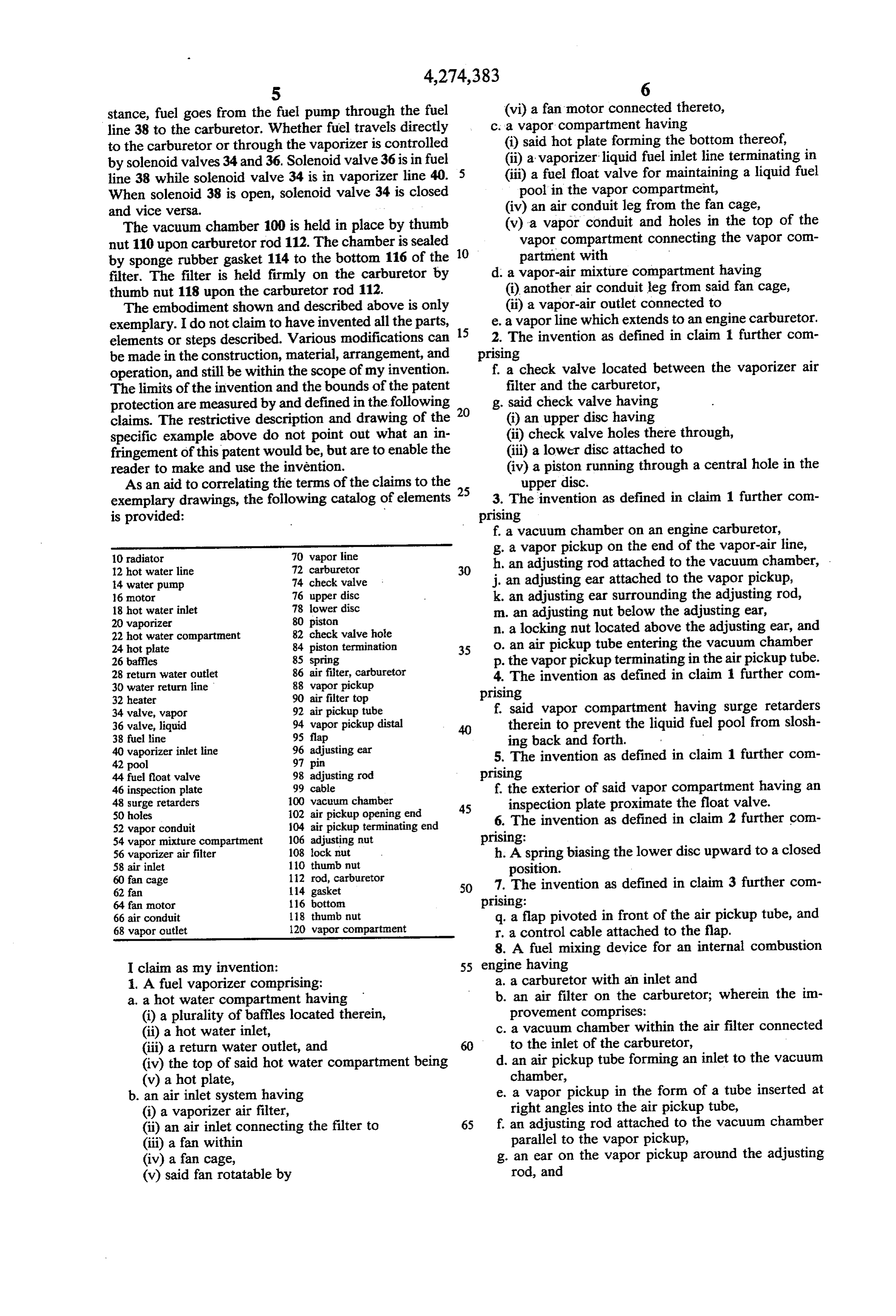
stance, fuel goes from the fuel pump through the fuel (vi) a fan motor connected thereto, line 38 to the carburetor. Whether fuel travels directly c. a vapor compartment having to the carburetor or through the vaporizer is controlled (i) said hot plate forming the bottom thereof, by solenoid valves 34 and 36. Solenoid valve 36 is in fuel (ii) a vaporizer liquid fuel inlet line terminating in line 38 while solenoid valve 34 is in vaporizer line 40. 5 (iii) a fuel float valve for maintaining a liquid fuel When solenoid 38 is open, solenoid valve 34 is closed pool in the vapor compartment, and vice versa. (iv) an air conduit leg from the fan cage, The vacuum chamber 100 is held in place by thumb (v) a vapor conduit and holes in the top of the nut 110 upon carburetor rod 112. The chamber is sealed 10 vapor compartment connecting the vapor con by sponge rubber gasket 114 to the bottom 116 of the partment with filter. The filter is held firmly on the carburetor by d. a vapor-air mixture compartment having thumb nut 118 upon the carburetor rod 112. (i) another air conduit leg from said fan cage, The embodiment shown and described above is only (ii) a vapor-air outlet connected to exemplary. I do not claim to have invented all the parts, 15 2.e. aThe vapor line which extends to an engine carburetor. invention as defined in claim 1 further com elements or steps described. Various modifications can be made in the construction, material, arrangement, and prising operation, and still be within the scope of my invention. f, a check valve located between the vaporizer air The limits of the invention and the bounds of the patent filter and the carburetor, protection are measured by and defined in the following 20 g. said check valve having claims. The restrictive description and drawing of the (i) an upper disc having specific example above do not point out what an in (ii) check valve holes there through, fringement of this patent would be, but are to enable the (iii) a lower disc attached to reader to make and use the invention. (iv) a piston running through a central hole in the As an aid to correlating the terms of the claims to the 25 upper disc.
exemplary drawings, the following catalog of elements 3. The invention as defined in claim 1 further com is provided: prising f. a vacuum chamber on an engine carburetor,
g. a vapor pickup on the end of the vapor-air line, 12 hot water line 72 carburetor 30 h, an adjusting
rod attached to the vacuum chamber, .
14 water pump 74 check valve j. an adjusting ear attached to the vapor pickup, 6 motor 76 upper disc k. an adjusting ear surrounding the adjusting rod, 18 hot water inlet 20 vaporizer 78 lower disc 80 piston m. an adjusting nut below the adjusting ear, 22 hot water compartment 82 check valve hole n. a locking nut located above the adjusting ear, and 24 hot plate 84 piston termination 35 o. an air pickup tube entering the vacuum chamber 26 baffles 85 spring p. the vapor pickup terminating in the airpickup tube. 28 return water outlet 86 air filter, carburetor 4. The invention as defined in claim 1 further com 30 water return line 88 vapor pickup prising
34 valve, vapor 92 air pickup tube f, said vapor compartment having surge retarders 36 valve, liquid 94 vapor pickup distal 40 therein to prevent the liquid fuel pool from slosh 38 fuel line 95 flap ing back and forth. 40 vaporizer inlet line 96 adjusting ear 5. The invention as defined in claim 1 further con
44 fuel float valve 98 adjusting rod prising 46 inspection plate 99 cable f. the exterior of said vapor compartment having an 48 surge retarders 50 holes 100 vacuum chamber 02 air pickup opening end 45 inspection plate proximate the float valve.
52 vapor conduit 04 air pickup terminating end 6. The invention as defined in claim 2 further con 54 vapor mixture compartment 106 adjusting nut prising:
56 vaporizer air filter 108 lock nut h. A spring biasing the lower disc upward to a closed 58 air inlet 110 thumb nut position.
60 fan cage 12 rod, carburetor 7. The invention as defined in claim 3 further com 62 fan 114 gasket 50 64 fan motor 116 botton prising:
66 air conduit 118 thumb nut q. a flap pivoted in front of the air pickup tube, and 68 vapor outlet 120 vapor compartment r. a control cable attached to the flap. 8. A fuel mixing device for an internal combustion
I claim as my invention: 55 engine having i. A fuel vaporizer comprising: a. a carburetor with an inlet and a, a hot water compartment having b. an air filter on the carburetor; wherein the in (i) a plurality of baffles located therein, provement comprises:
(ii) a hot water inlet, c. a vacuum chamber within the air filter connected (iii) a return water outlet, and to the inlet of the carburetor, (iv) the top of said hot water compartment being d. an air pickup tube forming an inlet to the vacuum (v) a hot plate, chamber, b. an air inlet system having e. a vapor pickup in the form of a tube inserted at (i) a vaporizer air filter, right angles into the air pickup tube, (ii) an air inlet connecting the filter to 65 f an adjusting rod attached to the vacuum chamber (iii) a fan within parallel to the vapor pickup, (iv) a fan cage, g. an ear on the vapor pickup around the adjusting (v) said fan rotatable by rod, and
Page 10
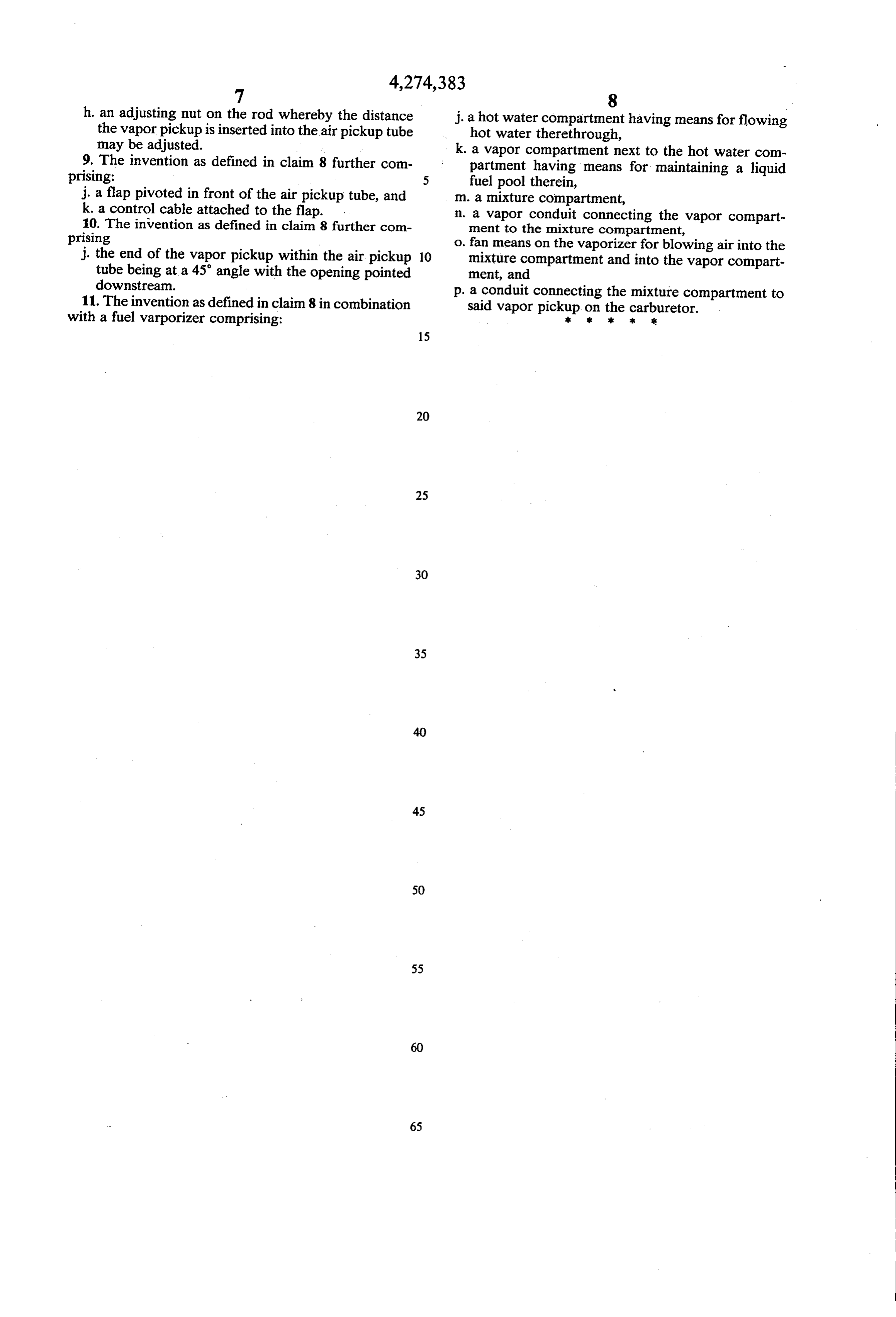
h. an adjusting nut on the rod whereby the distance j. a hot water compartment having means for flowing the vapor pickup is inserted into the air pickup tube hot water therethrough, may be adjusted. - k. a vapor compartment next to the hot water com 9. The invention as defined in claim 8 further com partment having means for maintaining a liquid prising: fuel pool therein, j, a flap pivoted in front of the air pickup tube, and m. a mixture compartment, k. a control cable attached to the flap. n. a vapor conduit connecting the vapor compart 10. The invention as defined in claim 8 further com ment to the mixture compartment, prising o. fan means on the vaporizer for blowing air into the j. the end of the vapor pickup within the air pickup 10 mixture compartment and into the vapor compart tube being at a 45° angle with the opening pointed ment, and downstream. p. a conduit connecting the mixture compartment to 11. The invention as defined in claim 8 in combination said vapor pickup on the carburetor. with a fuel varporizer comprising: sk s:
Provenance
- Collection
- Cited prior art
- Original PDF
- patentimages.storage.googleapis.com →
- Filed
- 1979-08-20
- Pages
- 10
- Method
- pdftotext (the PDF's own text layer) + pdftoppm 300dpi page scans
- Source
- Google Patents bibliographic record
- Granted
- 1981-06-23
- Inventors
- Jerry W. Adams; VAPOR MATIC CORP
- Transcribed from
- patentimages.storage.googleapis.com →