patent · US3779221
Internal combustion engine pollution control device
18 December 1973
Page 1 — bibliographic record
United States Patent (19) [11] 3,779,221 Gartner (45) Dec. 18, 1973 54 INTERNAL COMBUSTION ENGINE l,809,359 8/969 Germany .............................. 551445 POLLUTION CONTROL DEVICE 233,641 4/191 l Germany......................... 123119 B 76) Inventor: Joseph J. Gartner, 506 Queen Anne
Rd., Teaneck, N.J. 07666 Primary Examiner-Wendell E. Burns 22 Filed: Nov. 23, 1971 Attorney-Robert A. Maikis
5 l l Int. Cl....................... F02m 25/06, B01d 45/00 A pollution control device for automobile engines and 58) Field of Search................... 123/119 B; 55/442, the like is provided having a housing adapted to re 55/443, 444, 445, 446 ceive the blowby gasses from the engine crankcase.
The housing has a filter assembly for filtering the 56) References Cited blowby gasses and inlet means for mixing the gasses UNITED STATES PATENTS with air to increase oxidation of the pollutants in the 943,840 12/1909 Noyes............................... 55/.444 X gasses. The treated gasses are supplied to the engine 1903,731 4.1933 Gaston et al...................... 55/445 X intake manifold through the positive crankcase venti 1,915,521 6/1933 Edwards ............................... 551446 lation valve. Alternative embodiments of the invention 2, l l 1,936 3/1938 Murphy ............................ 55/445 X provide for heating the blowby gasses in the housing, 2,885,027 5/1959 Green............................... 551446 X eliminating the need for the positive crankcase venti 3,266,224 - 8/1966 Perretti............................. 551446X lation valve, and for sonic mixing of the air and 3,289,399 12/1966 Princiotta, Jr........................ 551445 blowby gasses in the housing.
FOREIGN PATENTS OR APPLICATIONS
858,288 5/1940 France ............................ 12311 19 B 12 Claims, 11 Drawing Figures
All
Nest
fifts
SZZZZZZZZZZZZZZZZZZZ N SSSSSSS a2
277AAA als
Page 2
Drawing sheet — no readable text.
Page 3
Drawing sheet — no readable text.
Page 4
Drawing sheet — no readable text.
Page 5
Drawing sheet — no readable text.
Page 6
INTERNAL COMBUSTON ENGINE POLLUTION SUMMARY OF THE INVENTION
CONTROL DEVICE
It is an object of this invention to provide a pollution
BACKGROUND OF THE INVENTION control device for reducing the airborne pollutants de 1. Field of the Invention rived from crankcase emissions of automobile internal This invention relates to air pollution control equip combustion engines and the like which is effective ment and more particularly to a pollution control de without repeated engine tune ups and other costly vice for internal combustion engines for automobiles maintenance.
and the like. It is a further object of this invention to provide an 2. Description of the Prior Art 10 internal combustion engine pollution control device Automobile internal combustion engines have fre which is adapted for use on a wide variety of quently been identified as a major source of air pollu commercially-available automobiles and other vehicles tion at the present time. During the combustion process and which is easily installed by the average automobile in the cylinders of the engine, various pollutants are OWer.
formed and released into the atmosphere. The pollut 15 It is a still further object of this invention to provide ants which cause the greatest concern are unburned hy an automobile engine pollution control device which is drocarbons, carbon monoxide, various oxides of nitro especially adapted for use on vehicles equipped with gen, and particulates, such as lead, for example. The positive crankcase ventilation.
pollutants reach the atmosphere from several sources It is an additional object of this invention to provide in the vehicle. Vapor from the fuel in the vehicle tank 20 an automobile engine pollution control device which and vapor from the carburetor produce a small but def maintains its effectiveness over long periods of time inite amount of pollution. The exhaust from the engine and which requires minimum maintenance. produces a large amount of airborne pollutants. A sub It is an additional object of this invention to provide stantial amount of pollutants, however, arise from 25 an automobile engine pollution control device which is crankcase emissions. mechanically rugged in construction, trouble-free in The crankcase emissions are derived in large part operation, and of relatively small size and weight. from so called "blowby' gasses which escape past the Briefly, the pollution control device of the invention piston rings in the engine cylinders during the power comprises a hollow housing having an inlet opening stroke. When the mixture of fuel and air in each cylin 30 adapted to be coupled to the crankcase of an engine to der is ignited by the spark plug, the gasses and particu receive the blowby gasses therefrom. The housing has lates which are formed in the cylinder are blown past an outlet opening which is adapted to be coupled to the the piston rings and into the crankcase. Apart from par intake manifold of the engine and an air inlet passage ticulates, such as lead, for example, the blowby gasses way disposed between the inlet and outlet openings for include unburned hydrocarbons, carbon monoxide and 35 supplying air to the blowby gasses in the housing. A me various oxides of nitrogen. chanical filter assembly is disposed in the housing be In order to minimize the pollution caused by emission tween the inlet and outlet openings for filtering the of crankcase gasses, a system of positive crankcase ven blowby gasses to remove the pollutants therefrom. Al tilation was developed in which the blowby gasses from ternative embodiments of the invention contemplate the crankcase were routed back into the engine com 40 means for heating the blowby gasses in the housing, a bustion chambers through the engine intake manifold. filter assembly which permits the PCV valve to be elim Since the routing of the blowby gasses into the cylin inated, and the addition of a sonic mixing chamber to ders produced a vacuum in the crankcase during en the housing for mixing the air and blowby gasses gine operation, a filtered air inlet was also provided to therein.
admit fresh air to ventilate the crankcase. A valve, usu 45 The nature of the invention and other objects and ad ally called the “PCV valve', in the blowby tube serves ditional advantages thereof will be more readily under to adjust the flow of blowby gasses to the flow of the stood by those skilled in the art after consideration of air-fuel mixture delivered by the carburetor and to pre the following detailed description taken in conjunction vent the air-fuel mixture from being drawn into the with the accompanying drawings.
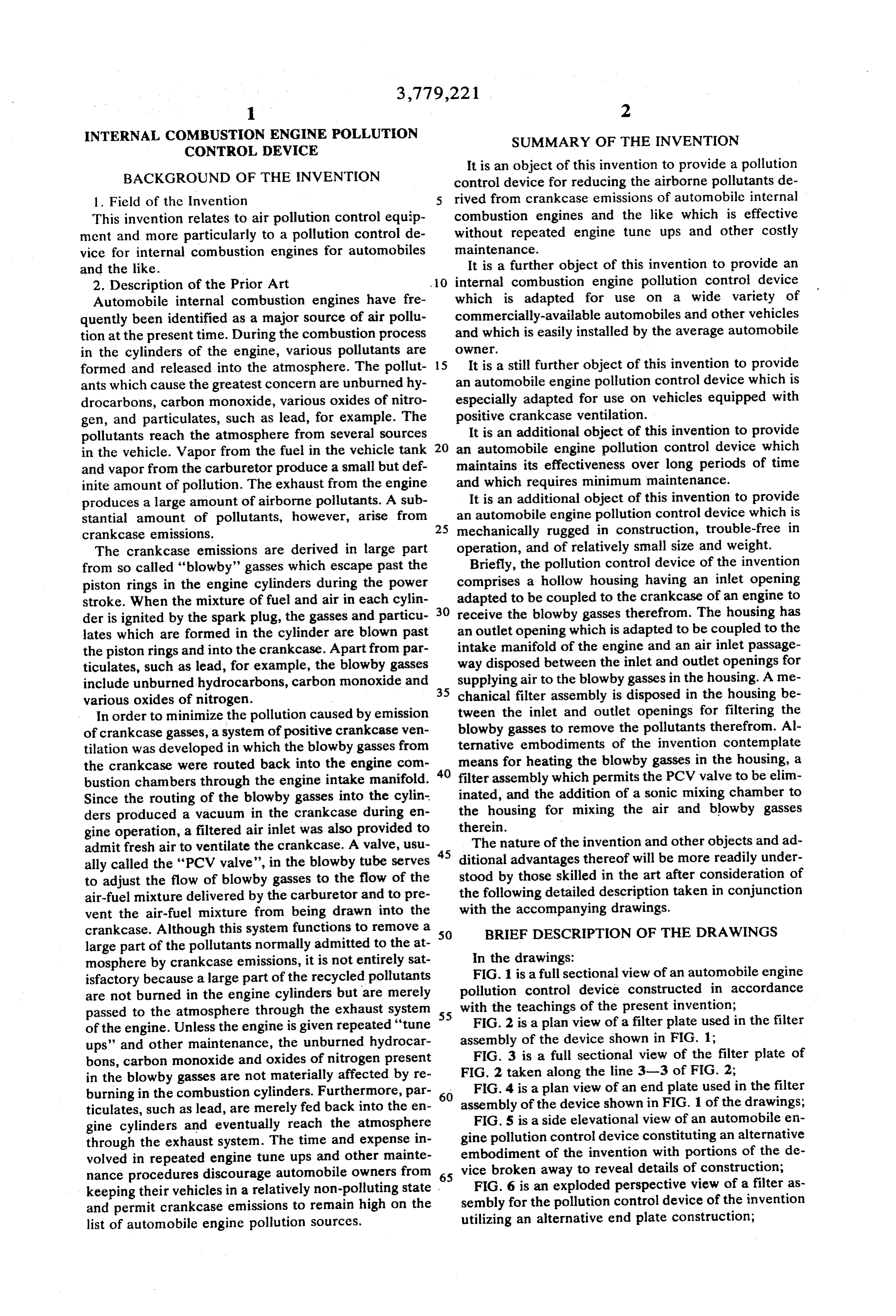
crankcase. Although this system functions to remove a 50 BRIEF DESCRIPTION OF THE ORAWINGS large part of the pollutants normally admitted to the at mosphere by crankcase emissions, it is not entirely sat In the drawings:
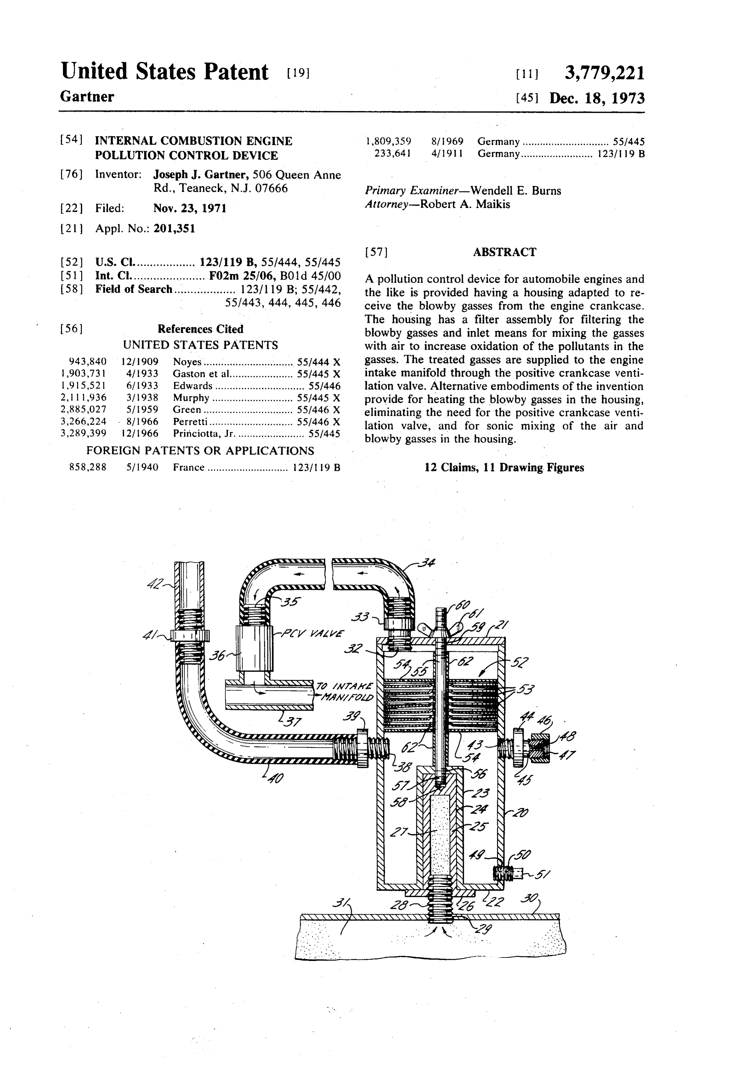
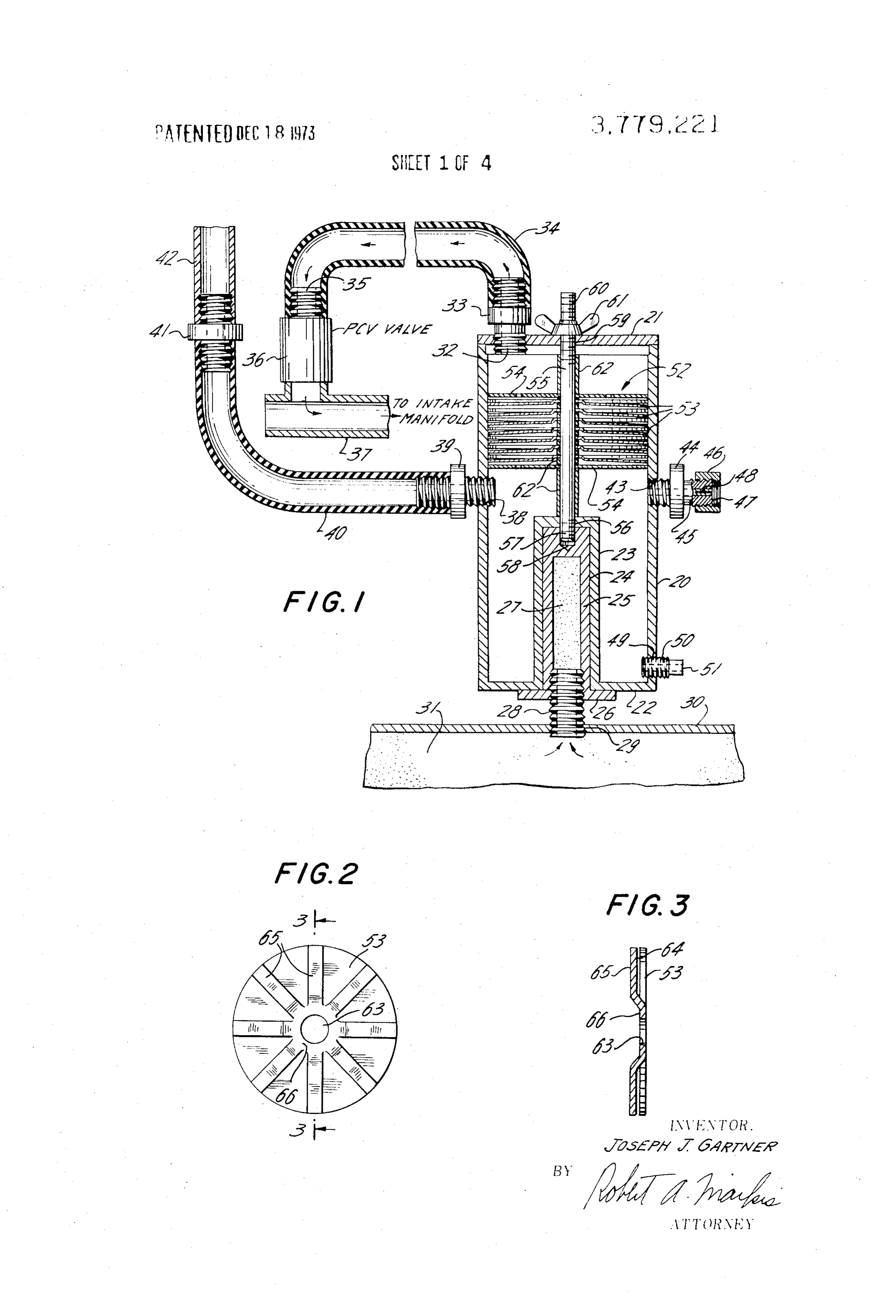
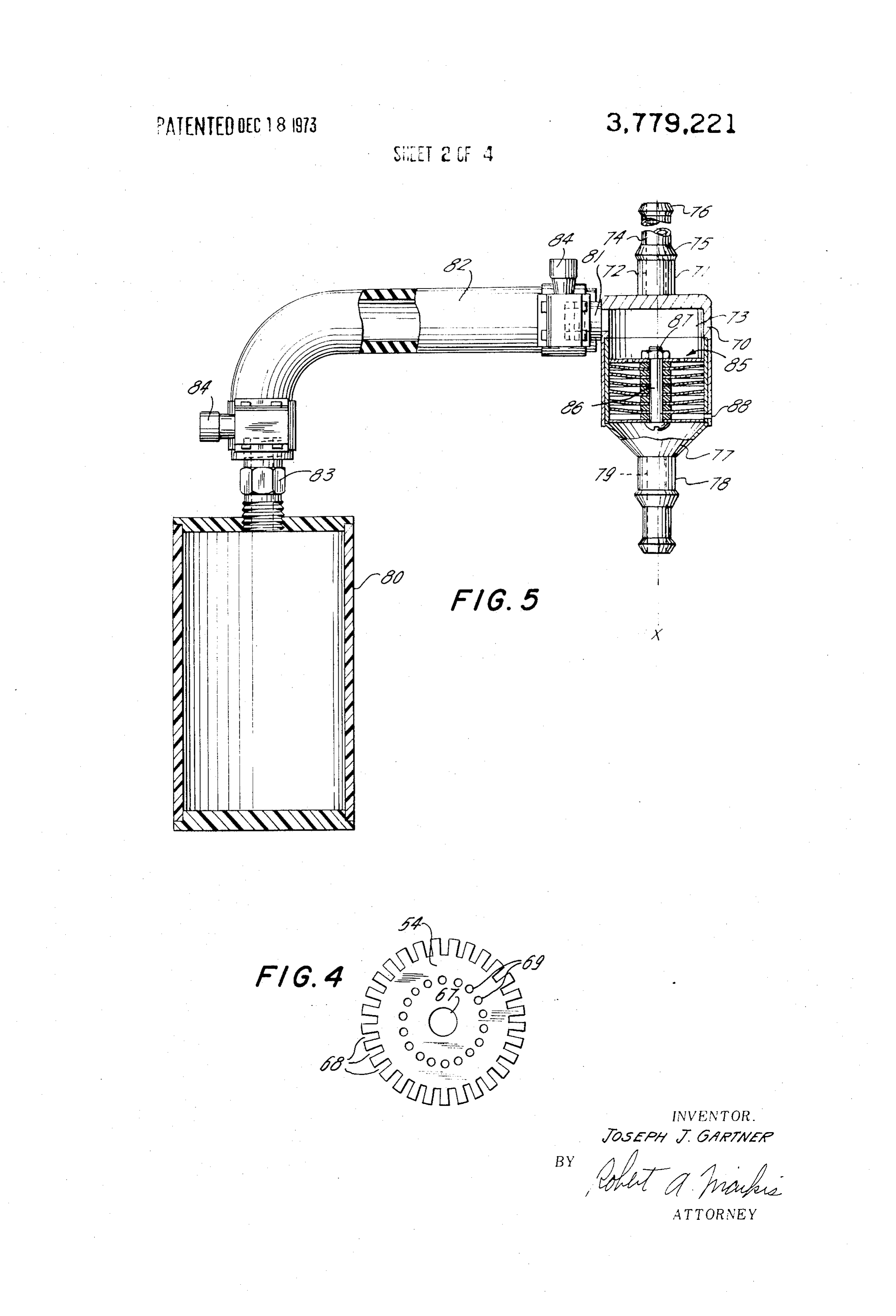
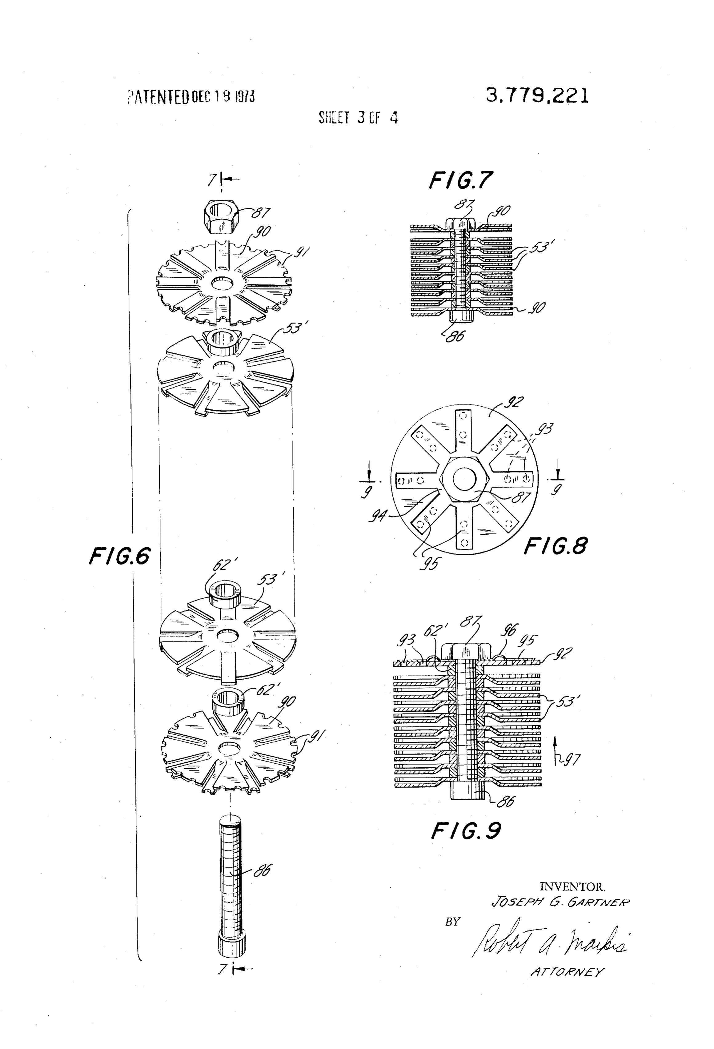
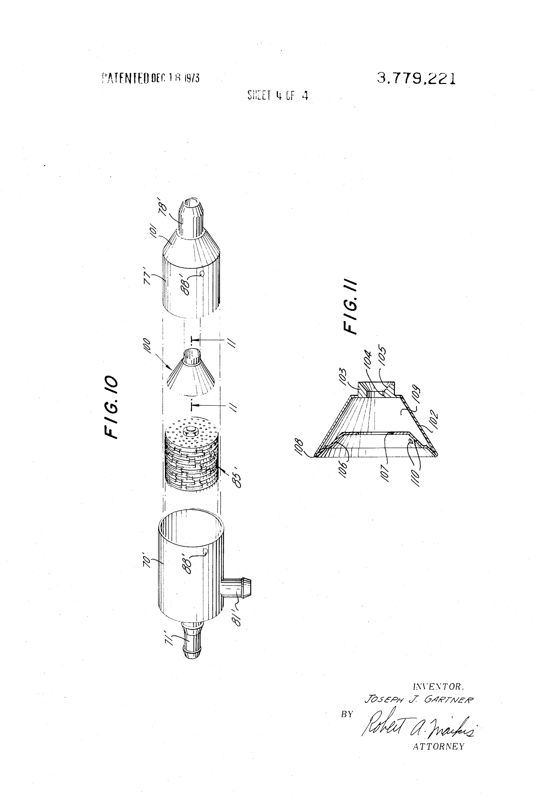
isfactory because a large part of the recycled pollutants FIG. 1 is a full sectional view of an automobile engine are not burned in the engine cylinders but are merely pollution control device constructed in accordance passed to the atmosphere through the exhaust system 55 with the teachings of the present invention; of the engine. Unless the engine is given repeated "tune FIG. 2 is a plan view of a filter plate used in the filter ups' and other maintenance, the unburned hydrocar assembly of the device shown in FIG. 1; bons, carbon monoxide and oxides of nitrogen present FIG. 3 is a full sectional view of the filter plate of in the blowby gasses are not materially affected by re FIG. 2 taken along the line 3-3 of FIG. 2; FIG. 4 is a plan view of an end plate used in the filter burning in the combustion cylinders. Furthermore, par 60 assembly ticulates, such as lead, are merely fed back into the en of the device shown in FIG. 1 of the drawings; gine cylinders and eventually reach the atmosphere FIG. S is a side elevational view of an automobile en through the exhaust system. The time and expense in gine pollution control device constituting an alternative volved in repeated engine tune ups and other mainte embodiment of the invention with portions of the de nance procedures discourage automobile owners from 65 vice broken away to reveal details of construction; FIG. 6 is an exploded perspective view of a filter as keeping their vehicles in a relatively non-polluting state and permit crankcase emissions to remain high on the sembly for the pollution control device of the invention list of automobile engine pollution sources. utilizing an alternative end plate construction;
Page 7
FIG. 7 is a full sectional view of the filter assembly of housing. A bushing 48, having a relatively small bore, FIG. 6 taken along the line 7-7 in FIG. 6; is press fitted into the bore 45 of the fitting to limit the FIG. 8 is an end elevational view of a filter assembly flow of air into the housing 20. The wire-mesh screen which utilizes a novel end plate construction which per 47 may, for example, comprise a No. 80 aluminum mits the PCV valve to be eliminated in most automo screen while the bushing 48 may have an internal diam bile engines; eter of 0.092 inches. The lower end of the cylindrical FIG.9 is a full sectional view of the filter assembly side wall of the housing 20 is also provided with a shown in FIG. 8 taken along the line 9-9 in FIG. 8; threaded aperture 49 which receives a threaded pipe FIG. 10 is an exploded perspective view of an auto fitting 50. The pipe fitting 50 serves as a drain to re mobile engine pollution control device constructed in move condensate from the interior of the housing and accordance with the present invention which utilizes a is provided with a drain block or plug 51. sonic mixing chamber; and As thus far described, it is believed apparent that the FIG. 1 is a full sectional view of the sonic mixing blowby gasses from the engine crankcase are con chamber of FIG. 10 taken along the line 11-11 of FIG. ducted to the interior of the housing 20 by means of the 10. 15 blowby fitting 42 and the hose 40. The gasses are then
DESCRIPTION OF THE PREFERRED
passed through a filter assembly, indicated generally as
EMBODIMENT OF THE INVENTION 52, to the upper portion of the housing interior, where they are conveyed by means of the hose 34 and the
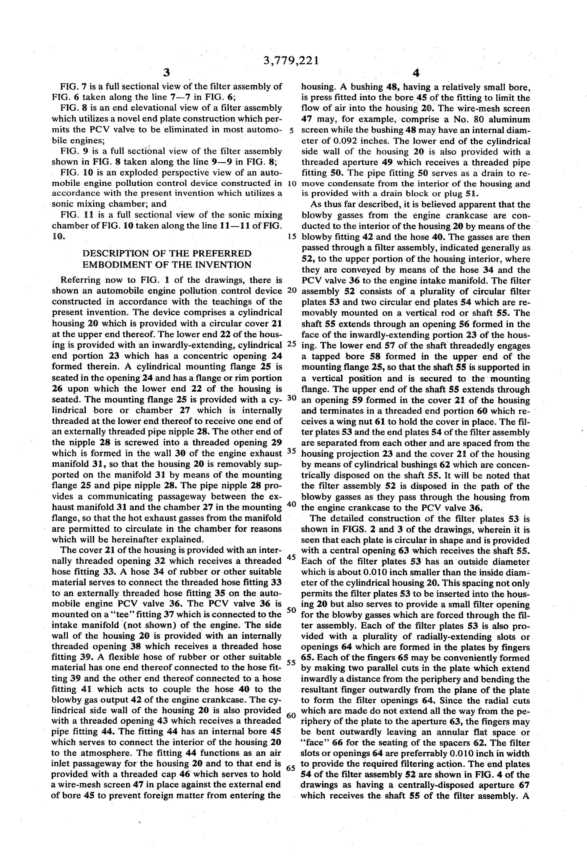
Referring now to FIG. 1 of the drawings, there is PCV valve 36 to the engine intake manifold. The filter shown an automobile engine pollution control device assembly 52 consists of a plurality of circular filter constructed in accordance with the teachings of the plates 53 and two circular end plates 54 which are re present invention. The device comprises a cylindrical movably mounted on a vertical rod or shaft 55. The housing 20 which is provided with a circular cover 21 shaft 55 extends through an opening 56 formed in the at the upper end thereof. The lower end 22 of the hous face of the inwardly-extending portion 23 of the hous ing is provided with an inwardly-extending, cylindrical 25 ing. The lower end 57 of the shaft threadedly engages end portion 23 which has a concentric opening 24 a tapped bore 58 formed in the upper end of the formed therein. A cylindrical mounting flange 25 is mounting flange 25, so that the shaft 55 is supported in seated in the opening 24 and has a flange or rim portion a vertical position and is secured to the mounting 26 upon which the lower end 22 of the housing is flange. The upper end of the shaft 55 extends through seated. The mounting flange 25 is provided with a cy 30 an opening 59 formed in the cover 21 of the housing lindrical bore or chamber 27 which is internally and terminates in a threaded end portion 60 which re threaded at the lower end thereof to receive one end of ceives a wing nut 61 to hold the cover in place. The fil an externally threaded pipe nipple 28. The other end of ter plates 53 and the end plates 54 of the filter assembly the nipple 28 is screwed into a threaded opening 29 are separated from each other and are spaced from the which is formed in the wall 30 of the engine exhaust 35 housing projection 23 and the cover 21 of the housing manifold 3, so that the housing 20 is removably sup by means of cylindrical bushings 62 which are concen ported on the manifold 31 by means of the mounting trically disposed on the shaft 55. It will be noted that flange 25 and pipe nipple 28. The pipe nipple 28 pro the filter assembly 52 is disposed in the path of the vides a communicating passageway between the ex blowby gasses as they pass through the housing from haust manifold 31 and the chamber 27 in the mounting 40 the engine crankcase to the PCV valve 36. flange, so that the hot exhaust gasses from the manifold The detailed construction of the filter plates 53 is are permitted to circulate in the chamber for reasons shown in FIGS. 2 and 3 of the drawings, wherein it is which will be hereinafter explained. seen that each plate is circular in shape and is provided The cover 21 of the housing is provided with an inter 45 with a central opening 63 which receives the shaft 55. nally threaded opening 32 which receives a threaded Each of the filter plates 53 has an outside diameter hose fitting 33. A hose 34 of rubber or other suitable which is about 0.010 inch smaller than the inside diam material serves to connect the threaded hose fitting 33 eter of the cylindrical housing 20. This spacing not only to an externally threaded hose fitting 35 on the auto permits the filter plates 53 to be inserted into the hous mobile engine PCV valve 36. The PCV valve 36 is SO ing 20 but also serves to provide a small filter opening mounted on a "tee' fitting 37 which is connected to the for the blowby gasses which are forced through the fil intake manifold (not shown) of the engine. The side ter assembly. Each of the filter plates S3 is also pro wall of the housing 20 is provided with an internally vided with a plurality of radially-extending slots or threaded opening 38 which receives a threaded hose openings 64 which are formed in the plates by fingers fitting 39. A flexible hose of rubber or other suitable 55 65. Each of the fingers 65 may be conveniently formed material has one end thereof connected to the hose fit by making two parallel cuts in the plate which extend ting 39 and the other end thereof connected to a hose inwardly a distance from the periphery and bending the fitting 41 which acts to couple the hose 40 to the resultant finger outwardly from the plane of the plate blowby gas output 42 of the engine crankcase. The cy to form the filter openings 64. Since the radial cuts lindrical side wall of the housing 20 is also provided 60 which are made do not extend all the way from the pe with a threaded opening 43 which receives a threaded riphery of the plate to the aperture 63, the fingers may pipe fitting 44. The fitting 44 has an internal bore 45 be bent outwardly leaving an annular flat space or which serves to connect the interior of the housing 20 "face'' 66 for the seating of the spacers 62. The filter to the atmosphere. The fitting 44 functions as an air slots or openings 64 are preferrably 0.010 inch in width inlet passageway for the housing 20 and to that end is 65 to provide the required filtering action. The end plates provided with a threaded cap 46 which serves to hold 54 of the filter assembly 52 are shown in FIG. 4 of the a wire-mesh screen 47 in place against the external end drawings as having a centrally-disposed aperture 67 of bore 45 to prevent foreign matter from entering the which receives the shaft 55 of the filter assembly. A
Page 8
S 6 plurality of notches 68 are provided around the periph haust manifold is still sealed because the chamber 27 ery of the plate and the central portion of the plate is does not communicate with the atmosphere. Similarly, provided with a series of openings 69. Neither of the the cover 21 of the unit may be removed by means of end plates 54 perfrom any filtering action. The end the wing nut 61 so that the entire filter assembly 52 can plates are made slightly larger in diameter than the fil 5 be withdrawn for easy cleaning. The maintenance of ter plates 53 so that the end plates serve to "center" the the filter is relatively simple since the design of the fil filter assembly in the cylindrical interior of the housing ter plates permits the trapped pollutants to gather in 20. The notches 68 and the openings 69 in the end liquid form at the bottom of the housing 20. The gath plates are made sufficiently large to permit cleaning of ered liquid is then easily withdrawn through the drain the assembled stack of filter elements by a blast of com 10 plug 51.
pressed air or by reverse flushing the filter with gasoline In practice, the housing 20, cover plate 21, filter or other suitable cleaning fluid. It should be noted that plates 53 and end plates 54 may be fabricated of alumi the total filtering area provided by the slots 64 of the num or any other suitable material which will withstand filter plates 53 and by the clearances between the filter the high operating temperatures involved and which plates and the inside diameter of the housing 20 should 15 will not chemically react with the matter in the blowby be at least equal to the cross-sectional area of the out gasses. The hose fittings 33 and 39, the air inlet assem put line from the housing 20, so that a "back pressure' bly 44, the drain plug assembly 50 and the pipe nipple is not caused to build up which could adversely affect 28 are preferably fabricated of brass or other material engine operation. which exhibits a relatively high structural strength and During engine operation, the pollution control device 20 which will not react with the pollutants in the blowby shown in FIGS. 1 through 4 of the drawings receives gasses. The mounting flange 25 should have a high de the blowby gasses from the crankcase of the engine. gree of structural strength and should obviously have a These gasses, as explained previously, contain un high coefficient of heat transfer. Accordingly, the burned hydrocarbons, carbon monoxide, oxides of ni mounting flange may, for example, be fabricated of trogen and particulates, such as lead, for example. The 25 brass or aluminum. It will be noted that the filter plates mixture of hot gasses and particulates passes through 53 of the device may be easily fabricated by stamping the filter assembly 52 where the particulates are largely them from sheet aluminum. The entire filter assembly filtered out by passage of the mixture through the slots may be assembled and inserted in the housing 20 by rel 64 and the clearances between the filter plates 53 and atively unskilled labor because the end plates 54 act as the interior wall of the housing 20. The mounting 30 a guide for insertion of the assembly and provide the flange 25 serves as a heat exchanger to heat the blowby correct filter clearances between the filter plates 53 gasses from the hose 40 when they are admitted to the and the walls of the housing 20. Finally, it is believed housing interior. The chamber 27 in the mounting apparent that the design of the pollution control device flange communicates directly with the exhaust mani 35 of the invention permits the device to be easily installed fold of the engine so that a large heat source is available in many of the different types of automobiles on the for the heating of the blowby gasses. At the same time, road today by the average automobile owner. For auto the air inlet assembly 44 functions to admit air to the mobiles equipped with the PCV system of crankcase interior of the housing in controlled amounts. By virtue emission control, it is only necessary to break the con of this combined action, large particles of unburned hy 40 nection of the blowby hose 42 to the PCV valve 36 and drocarbon are deposited on the filter plates and the insert the unit by means of the provided hose fittings. carbon monoxide present is largely converted to the The installation of the unit on the exhaust manifold 31 less harmful form of carbon dioxide. Similarly, it is be merely requires the drilling and tapping of a suitable lieved that the oxides of nitrogen present in the blowby opening in the manifold.
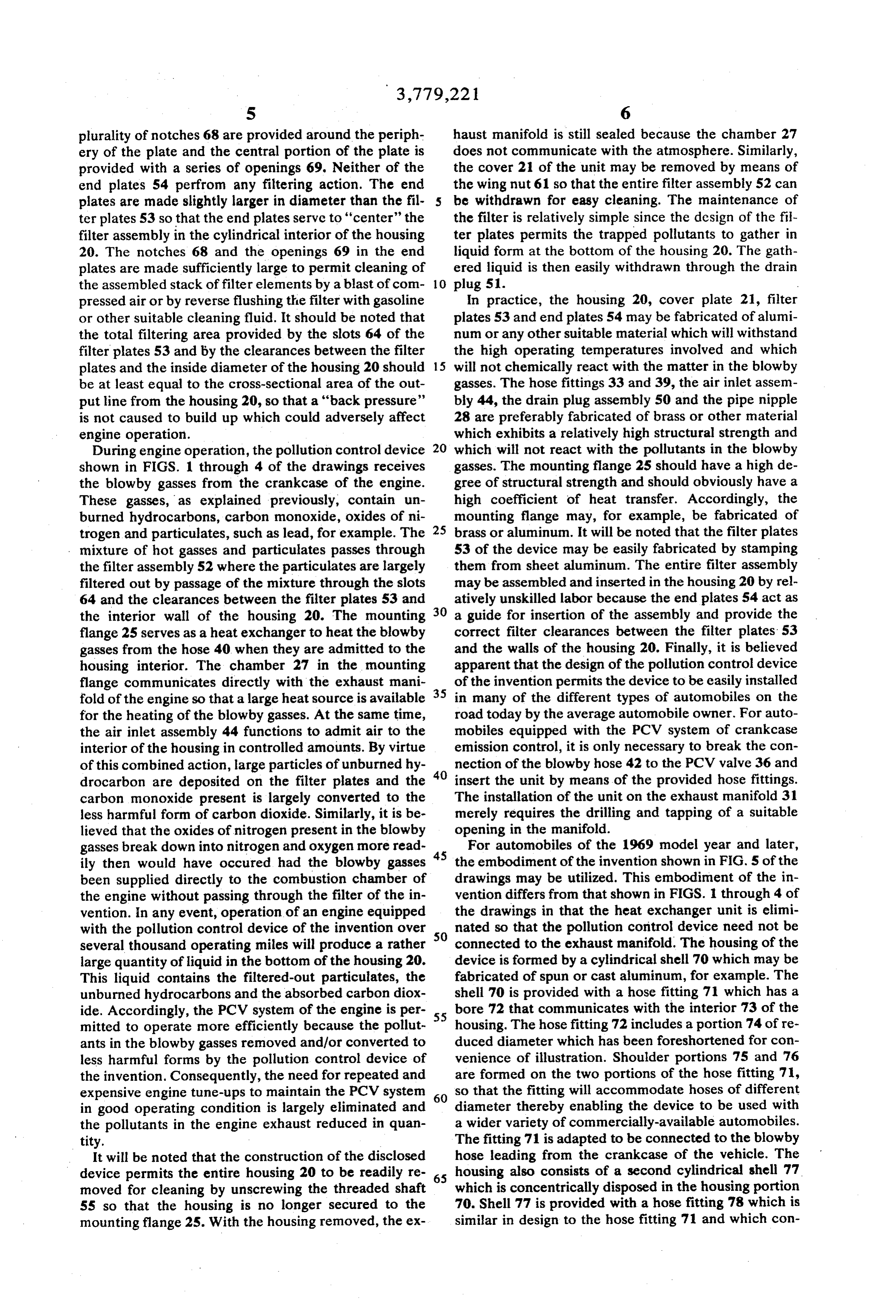
gasses break down into nitrogen and oxygen more read 45 For automobiles of the 1969 model year and later, ily then would have occured had the blowby gasses the embodiment of the invention shown in FIG. S of the been supplied directly to the combustion chamber of drawings may be utilized. This embodiment of the in the engine without passing through the filter of the in vention differs from that shown in FIGS. 1 through 4 of vention. In any event, operation of an engine equipped the drawings in that the heat exchanger unit is elimi with the pollution control device of the invention over 50 nated so that the pollution control device need not be several thousand operating miles will produce a rather connected to the exhaust manifold. The housing of the large quantity of liquid in the bottom of the housing 20. device is formed by a cylindrical shell 70 which may be This liquid contains the filtered-out particulates, the fabricated of spun or cast aluminum, for example. The unburned hydrocarbons and the absorbed carbon diox shell 70 is provided with a hose fitting 71 which has a ide. Accordingly, the PCV system of the engine is per 55 bore 72 that communicates with the interior 73 of the mitted to operate more efficiently because the pollut housing. The hose fitting 72 includes a portion 74 of re ants in the blowby gasses removed and/or converted to duced diameter which has been foreshortened for con less harmful forms by the pollution control device of venience of illustration. Shoulder portions 75 and 76 the invention. Consequently, the need for repeated and are formed on the two portions of the hose fitting 71, expensive engine tune-ups to maintain the PCV system 60 so that the fitting will accommodate hoses of different in good operating condition is largely eliminated and diameter thereby enabling the device to be used with the pollutants in the engine exhaust reduced in quan a wider variety of commercially-available automobiles. tity. The fitting 71 is adapted to be connected to the blowby It will be noted that the construction of the disclosed hose leading from the crankcase of the vehicle. The device permits the entire housing 20 to be readily re 65 housing also consists of a second cylindrical shell 77 moved for cleaning by unscrewing the threaded shaft which is concentrically disposed in the housing portion 55 so that the housing is no longer secured to the 70. Shell 77 is provided with a hose fitting 78 which is mounting flange 25. With the housing removed, the ex similar in design to the hose fitting 71 and which con
Page 9
tains a passageway 79 communicating with the interior characters with a prime notation are employed to iden 73 of the housing. This hose fitting is adapted to be tify elements which are the same as or similar to the connected to the hose leading to the PCV valve of the correspondingly numbered elements in FIGS. engine. through 4. The filter plates 53' are basically the same In FIG. 5 of the drawings, the central axis X-X of 5 as the filter plates 53 in FIG. 2 of the drawing except the housing assembly is shown in a vertical position for that they are of smaller diameter. The end plates 90 in convenience of illustration. In practice, however, the this filter assembly are basically the same as the filter X-X axis would be substantially horizontal to permit plates 53' and may be made on the same production drainage of the condensate in the housing to a storage equipment. However, each of the end plates 90 is pro container 80. To this end, the housing portion 70 is 10 vided with a plurality of notches 9 about the periphery provided with a hose fitting 81 which communicates thereof so that neither end plate performs any filtering with the interior 73 of the housing and which is adapted function. The notches 91 in each end plate permit the to receive one end of a drain hose 82. The other end filter assembly to be cleaned by reverse flushing or of the hose 82 is secured to a hose fitting 83 located in compressed air blasts. They also permit any condensate the top of the container 80. Hose clamps 84 are em 15 trapped by the filter plates 53' to drain into the portion ployed to insure a good connection of the hose 82 to of the housing adjacent the hose fitting 81. Although the fittings 81 and 83. With the X-X axis of the hous this type of end plate does not provide the support and ing in a substantially horizontal position, the conden guide functions of the end plate shown in FIG. 4 of the sate forming in the interior 73 of the housing will drain drawings because its diameter is the same as the filter by gravity through the hose 82 into the storage con 20 plates 53', it does offer the advantage that it may be tainer 80. In this embodiment of the invention, the fil made on the same production machines used for the ter assembly 85 is again made up of the filter plates and filter plates thereby minimizing production costs. A end plates shown in FIGS. 2, 3 and 4 of the drawings. completely assembled stack of the filter plates 53' and The plates are, however, held together by a short bolt end plates 90 is shown in FIG. 7 of the drawings. It may 86 and a nut 87 so that the entire filter assembly may 25 be noted that the overall operating efficiency of the fil be slidably removed from the interior 73 of the hous ter assembly depends upon the number of filter plates ing. The air inlet for this embodiment of the invention employed. Since the filter plates 53' employed in the is considerably simplified in that it may comprise a hole embodiment of FIG. 5 of the drawings are generally of 88 drilled through both the housing portions 70 and 77. much smaller diameter than the filter plates 53 em The drilled or otherwise formed hole 88 may, for exam 30 ployed in the embodiment of FIG. 1 of the drawings, a ple, be 0.062 inch in diameter. larger number of plates should be utilized to provide The embodiment of the invention shown in FIG. S of the same filter area.
the drawings should be of considerably smaller size FIGS. 8 and 9 of the drawings illustrate a modified than the embodiment shown in FIG. 1 of the drawings. 35 filter assembly which performs the "check valve' func The smaller size of the housing in the arrangement of tion of the PCV valve in the automobile engine. As ex FIG. 5 permits a much smaller amount of heat to be ra plained previously, the PCV valve prevents the air and diated or otherwise lost to the atmosphere, thereby fuel mixture in the engine intake manifold from being providing a higher operating temperature for the entire drawn back into the crankcase during operation of the unit. The reduced loss permits the heat exchanger engine. In the filter assembly shown in FIGS. 8 and 9, shown in FIG. 1 of the drawings to be eliminated and 40 the filter plates 53', spacers 62", bolt 86 and nut 87 are materially simplifies the construction of the unit. The the same as the corresponding elements shown in FIG. embodiment of the invention shown in FIG. 1 of the 6 of the drawings. In this embodiment, one of the end drawings with a heat exchanger would be especially plates 92 is provided with a plurality of radially adapted for use on 1968 or earlier model automobiles 45 disposed apertures 93. A leaf spring arrangement 94 which are not provided with a thermostatically having a plurality of radially-disposed fingers 95 is controlled air heater for the carburetor air intake. The placed over the end plate 92 and secured in the filter embodiment shown in FIG. 5 would be suited for use stack by the bolt 86 and nut 87. The fingers 95 of the with the 1969 and later model automobiles which are leaf spring are disposed over the apertures 93 in the provided with air intake heaters. In practice, housing 50 end plate 92. Each of the fingers 95 is provided with a portions 70 and 77 may be easily fabricated of alumi bent or crimped portion 96 so that the finger is securely num while the container 80 may comprise a simple pressed against the surface of the plate 92, to thereby plastic container which is easily emptied by the auto effectively seal the apertures 93. The diameter of the mobile owner. In all other respects, however, the oper end plate 92 is then made large enough so that the plate ation of this embodiment is the same as the embodi 55 effectively provides a relatively gas-tight barrier across ment shown in FIG. 1 of the drawings. If desired, the the housing portion 77 of the device. The filter assem container 80 may be formed of a transparent or translu bly is then inserted into the housing portion so that the cent material so that the level of accumulated fluid may end plate 92 is adjacent the hose fitting 78 which leads be easily noted by the motorist and emptied at regular to the engine intake manifold. The direction of flow of intervals. It may also be noted that the pollution control 60 the blowby gasses through the filter assembly is shown device shown in FIG. 5 of the drawings could be oper in FIG. 9 of the drawings by the arrow 97. From an in ated with the X-X axis of the housing in a substan spection of this figure, it is believed apparent that the tially vertical position if the assembly were so oriented pressure exerted by the blowby gas flow will lift the fin that the hose fitting 81 was disposed at the bottom of gers 95 of the leaf spring assembly and permit the fil the housing so that accumulated fluids could drain by 65 tered gasses to be applied to the intake manifold. When gravity into the container 80. a reverse flow occurs, however, the fingers 95 are An exploded perspective view of the filter assembly forced against the openings 93 in the plate 92 so that 85 is shown in FIG. 6 of the drawings wherein reference the air-fuel mixture in the intake manifold is not drawn
Page 10
back into the engine crankcase. Accordingly, this em 1. A pollution control device for internal combustion bodiment of the filter assembly effectively permits the engines having a positive crankcase ventilation valve elimination of the check valve function of the PCV comprising valve in the automobile engine. This embodiment of a hollow housing having an inlet opening adapted to the invention could therefore be employed on early 5 be coupled to the crankcase of said engine to re model automobiles which are not provided with posi ceive the blowby gasses therefrom, an outlet open tive crankcase ventilation systems. For new cars, this ing adapted to be coupled to said positive crank modification of the filter assembly could effectively case ventilation valve of the engine, and an air inlet permit the elimination of the PCV valve. passageway for supplying air to the blowby gasses; FIGS. 10 and 11 of the drawings illustrate a modifica 10 and tion of the pollution control device of the invention a mechanical filter assembly disposed in said housing which provides for sonic mixing of the blowby gasses between said inlet and outlet openings for filtering and the air drawn into the filter housing during opera the blowby gasses to remove the pollutants there tion. In describing this modification of the invention, 15 from.
reference characters with a prime notation will be em 2. A pollution control device as claimed in claim 1 ployed to identify components which are the same as further comprising or similar to the correspondingly numbered compo means adapted to be coupled to the exhaust manifold nents in FIG. 5 of the drawings. As seen in FIG. 10, a of the engine for heating the blowby gasses in said baffle element 100 is disposed in the housing portion 20 housing.
77' which leads to the engine PCV valve. The baffle 3. A pollution control device as claimed in claim 2 100 is designed to fit into the conical section 101 of the wherein housing portion 77' and is downstream of the air inlet said filter assembly comprises a stack of spaced filter aperture 88". Accordingly, the filtered blowby gasses plates, each of said filter plates having a plurality mix with the stream of inlet air at this point in the de 25 of spaced filter apertures therein, vice and are applied together to the baffle 100. As seen said housing has an inwardly projecting wall portion in FIG. 11, the baffle 100 comprises a conical shell 102 defining a cavity therein, and which is truncated at one end thereof to provide a cy said heating means comprises a heat exchanger re lindrical shoulder portion 103. The shoulder portion movably disposed in said cavity. 103 has an opening 104 formed therein which is coun 30 4. A pollution control device as claimed in claim 1 terbored at end 105 thereof to produce a larger diame wherein said filter assembly comprises ter passageway leading into the output hose fitting 78'. a shaft member,
The input side of the baffle 100 is closed with a a stack of spaced filter plates slidably disposed on "dished' circular plate 106 which has an opening 107 said shaft member for support thereby, each of said formed therein. The dished plate 106 may be secured 35 filter plates having a plurality of radially-disposed to the end 108 of the shell 102 by any convenient filter slots formed therein, and - a pair of end plates slidably disposed on said shaft means, such as swaging, for example. This arrangement forms a sonic mixing cavity or chamber 109 in the baf member for support thereby at opposite ends of fle in which the air from the air inlet opening 88 is said stack of filter plates. mixed with the filtered blowby gasses. The larger diam 40 5. A pollution control device fingers claimed in claim eter aperture 107 in the plate 106 cooperates with the 4 wherein said filter slots are formed by a plurality of smaller diameter opening 104 in the shoulder portion radially-disposed fingers cut from the filter plate to 103 to provide a "venturi" arrangement. The inlet air leave a plurality of radially-disposed slotted openings in and the blowby gasses circulate in the cavity 109 and the plate, each of said fingers being supported at one generate sonic waves which greatly enhance the mixing end thereof by the plate and being spaced a distance function, so that more oxygen is made available to the from the plane of the plate, so that the radially carbon monoxide pollutants to more readily convert disposed edges of the ingers cooperate with said slotted them to carbon dioxide. If desired, a number of small openings to form the filter slots.
openings 110 may be provided in the dished plate 106 SO 6. A pollution control device as claimed in claim 4 to facilitate drainage of any condensates trapped in the wherein each of said end plates has a larger area than cavity 109. Although it is believed that the dimensions the area of each of said filter plates, so that the filter as of the apertures 104 and 107 are not critical, it has sembly said end is centered in said housing by the end plates, plates being provided with openings having an been found that a diameter of 5/32 inch for the opening 104 and a diameter of 7/32 inch for the opening 107 55 area considerably larger than the area of said filter will provide and adequate sonic mixing effect when the plates so that the filter assembly may be cleaned by the distance between the apertures ranges from 0.210 inch passage of a cleaning fluid therethrough. to 0.280 inch. 7. A pollution control device as claimed in claim 5 It is believed apparent that many changes could be wherein each of said end plates is formed by one of said made in the construction and described uses of the filter plates and has a plurality of notches formed about foregoing pollution control device and many seemingly 60 the periphery thereof to permit cleaning of the filter as different embodiments of the invention could be con sembly and drainage of the condensate therefrom. structed without departing from the scope thereof. Ac 8. A pollution control device as claimed in claim 4 cordingly, it is intended that all matter contained in the wherein one of said end plates has a plurality of radial ly-disposed apertures formed therein and a leaf spring above description or shown in the accompanying draw 65 having ings shall be interpreted as illustrative and not in a lim vided toasealplurality of radially-disposed fingers is pro the apertures, so that gas flow through the iting sense.
What is claimed is: filter assembly is limited to one direction.
Page 11
9. A pollution control device as claimed in claim 1 said hollow housing is cylindrical, further comprising said filter plates and end plates are circular, and a sonic mixing chamber disposed in said housing for said inlet opening and outlet opening are formed by mixing the blowby gasses with the air from said air cylindrical hose fittings disposed at opposite ends inlet passageway, said mixing chamber having a 5 of said housing.
passageway with a throat portion of reduced cross 12. A pollution control device as claimed in claim 11 sectional area which is adapted to receive the wherein blowby gasses and air.
10. A pollution control device as claimed in claim 6 each of said radially-disposed filter slots is approxi
mately 0.010 inch wide, and said hollow housing is provided with a drain opening, the total filtering area provided by said filter slots and and the clearance between said stack of filter plates and a closed storage container is connected to said drain the inside diameter of said housing is at least equal opening to receive pollutants filtered from said to the cross-sectional area of said outlet opening, blowby gasses. 15 so that no back pressure is formed during operation 11. A pollution control device as claimed in claim 10 of the device.
wherein sk ck xk ck ck
Provenance
- Collection
- Cited prior art
- Original PDF
- patentimages.storage.googleapis.com →
- Filed
- 1971-11-23
- Pages
- 11
- Method
- pdftotext (the PDF's own text layer) + pdftoppm 300dpi page scans
- Source
- Google Patents bibliographic record
- Granted
- 1973-12-18
- Inventors
- J Gartner
- Transcribed from
- patentimages.storage.googleapis.com →