patent · US4706651
Solar solids reactor
17 November 1987
Page 1 — bibliographic record
United States Patent (19) 11) Patent Number: 4,706,651 Yudow (45) Date of Patent: Nov. 17, 1987 (54). SOLAR SOLIDS REACTOR 4,619,244 10/1986 Marks .................................. 126/451 4,627,418 12/1986 Gibson et al. ....................... 126/451 75) Inventor: Bernard D. Yudow, Chicago, Ill. FOREIGN PATENT DOCUMENTS 73) Assignee: The United States of America as 0126810 1/1901 Fed. Rep. of Germany ...... 432/194 represented by the United States
Department of Energy, Washington, Primary Examiner-Samuel Scott
D.C. Assistant Examiner-H. A. Odor 21 Appl. No.: 832,617 r
Attorney, Agent, or Firm-L. E. Carnahan; Roger S.
Gaither; Judson R. Hightower 22 Filed: Feb. 24, 1986 57 ABSTRACT 51) Int. Cl."................................................. F24J 2/00 A solar powered kiln is provided, that is of relatively 52 U.S. C. .................................... 126/451; 126/450; simple design and which efficiently uses solar energy. 126/417; 432/120; 432/121; 432/200 The kiln or solids reactor includes a stationary chamber 58 Field of Search ............... 432/120, 121, 194, 200, with a rearward end which receives solid material to be 432/201, 202; 34/93, 179, 182, 203; 126/451, reacted and a forward end through which reacted mate 450,438, 417 rial is disposed of, and a screw conveyor extending 56) References Cited along the bottom of the chamber for slowly advancing
solar energy is directed to an aperture at the forward 1,575,470 3/1926 Weber et al..... ... 432/194 end of the chamber to heat the solid material moving 1,957,347 5/1934 McKinnon ... ... 432/200 along the bottom of the chamber. The solar energy can 2,550,948 5/1951 Tusson .................................. 34/137 be reflected from a mirror facing at an upward incline, 2,604,059 7/1952 Warrington. ... 432/194 through the aperture and against a heat-absorbing mate 3,849,063 11/1974 Eichenlaub. ... 432/194 3,972,316 8/1976 Alkauab ....... ... 126/417 rial near the top of the chamber, which moves towards 4,120,646 10/1978 Groff et al... ... 432/121 the rear of the chamber to distribute heat throughout 4,222,987 9/1980 Keller ........... ... 432/121 the chamber. Pumps at the forward and rearward ends 4,224,286 9/1980 Murase et al. ... 432/194 of the chamber pump heated sweep gas through the 4,229, 184 10/1980 Gregg .............. ... 126/438 length of the chamber, while minimizing the flow of gas 4,284,839 8/1981 Johnson ... ... 126/438 through an open aperture through which concentrated 4,365,615 12/1982 McIvin ................. ... 126/438 sunlight is received.
4,443,186 4/1984 Shell ..................... ... 126/417 20 Claims, 5 Drawing Figures
Messrs.
Fis
VACCNvAsvavivXOR
S SSSSSSSSSSSSSSSSX
Praecot swell. P
Clas Cairy 74
Page 2
Drawing sheet — no readable text.
Page 3
Drawing sheet — no readable text.
Page 4
out of the rearward end of the chamber, but also
SOLAR SOLIDS REACTORBACKGROUND OF pumped in near the forward end of the chamber at a rate THE INVENTION that minimizes the flow of air or other gas either into or out of the chamber through the aperture.
The novel features of the invention are set forth with
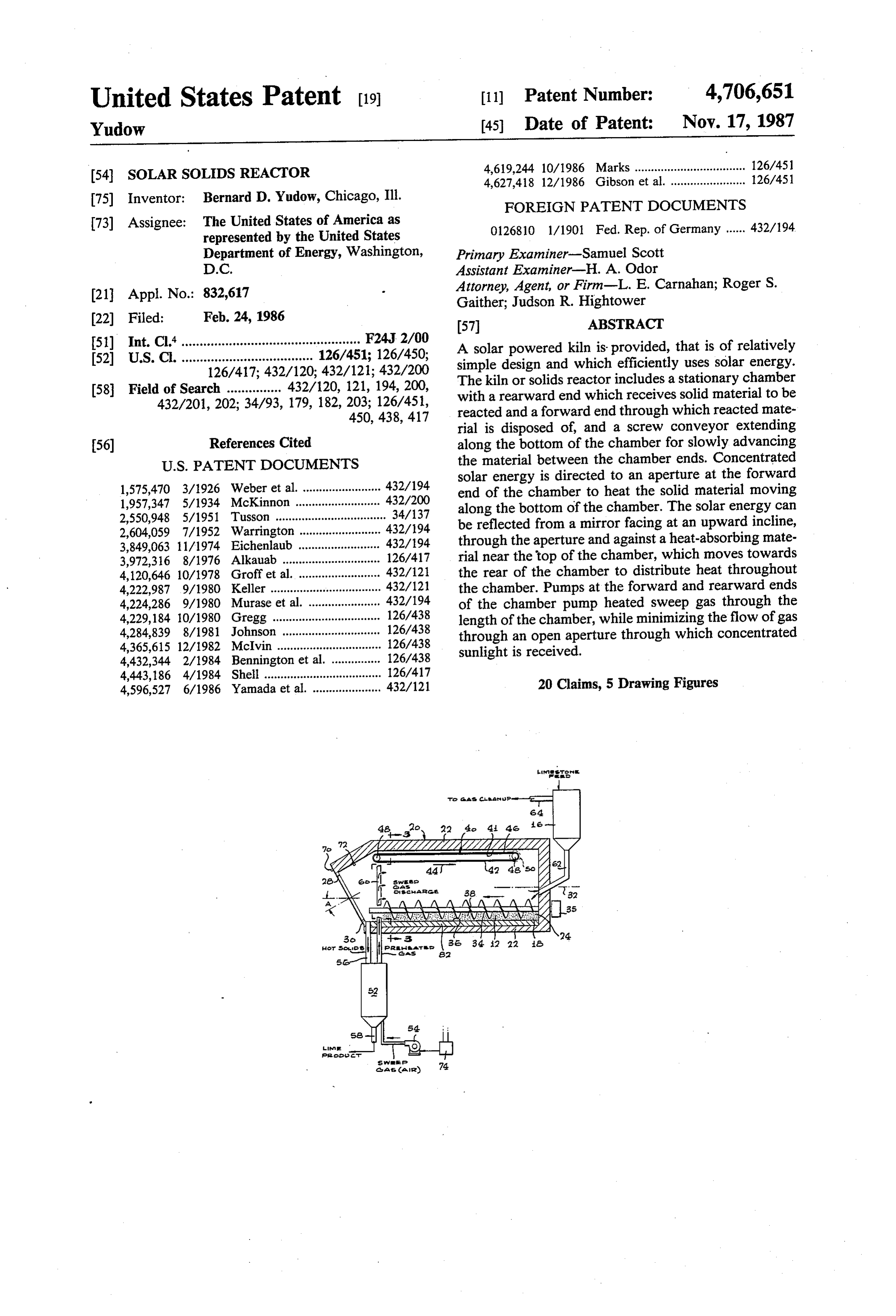
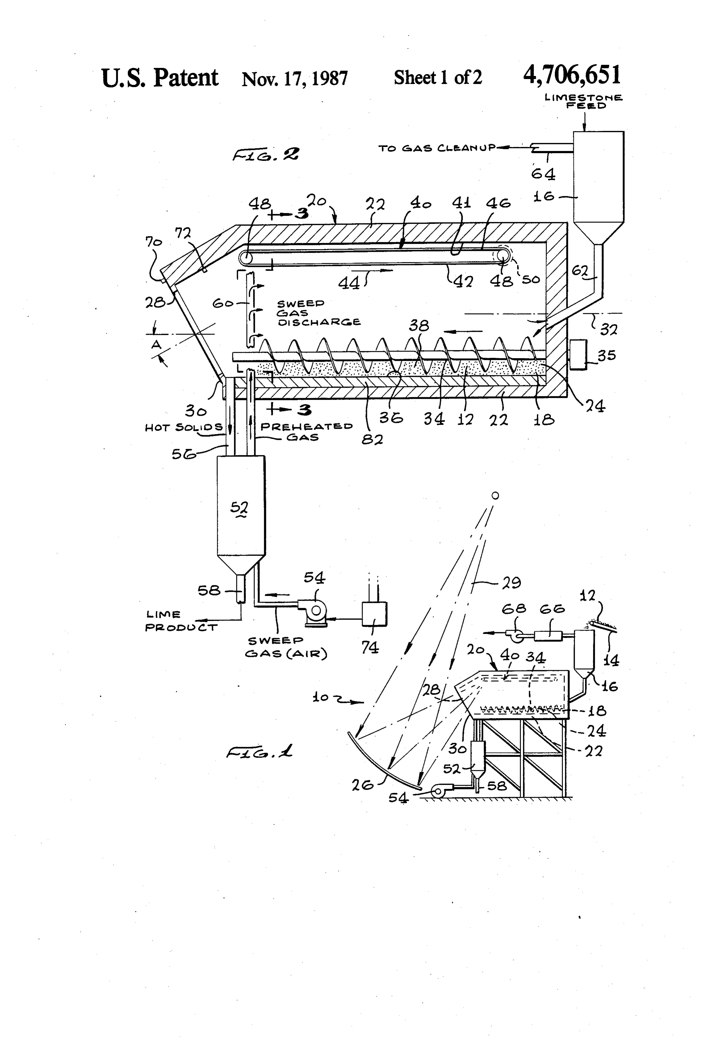
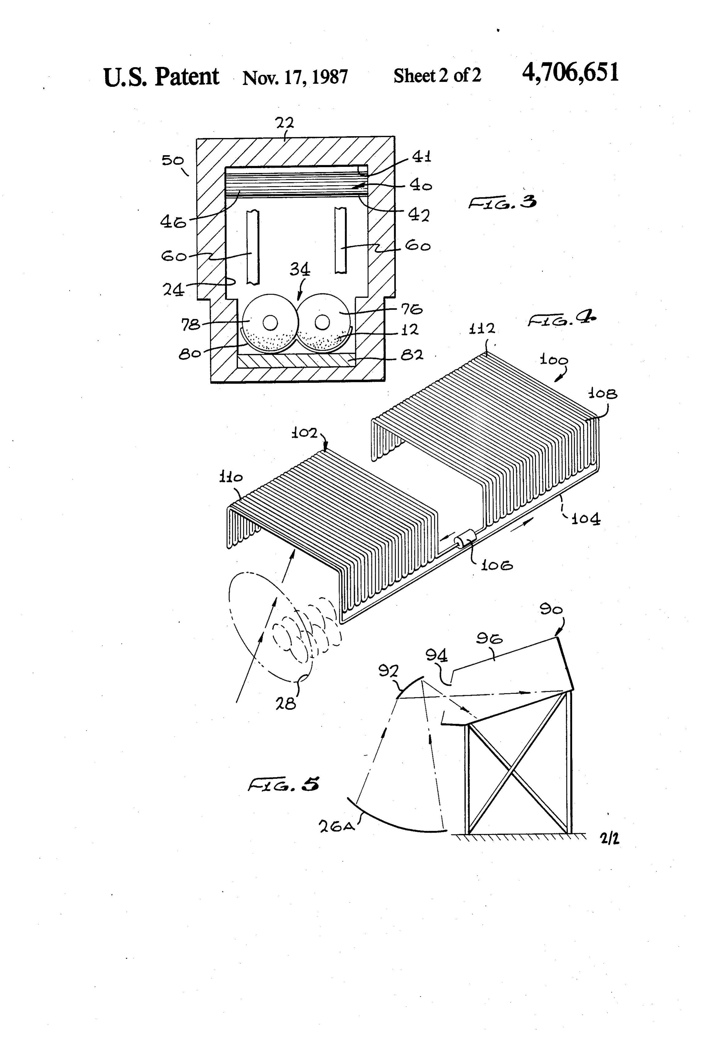
The Government has rights in this invention pursuant 5 particularity to Contract No. DE-AC03-82SF11662 awarded by the in the appended claims. The invention will U.S. Department of Energy. be best understood from the following description when Kilns are used as solid reactors, as for the calcination read in conjunction with the accompanying drawings. (heating without binding) of calcium carbonate, to turn BRIEF DESCRIPTION OF THE DRAWINGS limestone feed into a lime product. Some or all of the 10 heating energy can be obtained from concentrated sun FIG. 1 is a simplified side elevation view of a solar light. A typical prior art kiln includes a chamber that powered solids reactor constructed in accordance with continually rotates about a largely horizontal axis while oneFIG. embodiment of the invention. 2 is a sectional view of the reactor of FIG. 1.
solids fed into its rearward end slowly advance towards FIG.3 is a view taken on the line 3-3 of FIG. 2. the forward end from which they are removed. A 15 FIG. 4 is a partial perspective view of another solar sweep gas, such as air, may also flow along the length of the chamber to maintain a low partial pressure of car powered reactor which includes a heat exchanger. bon dioxide above the reactants. One type of prior art FIG. 5 is a simplified view of another solar powered solar kiln is shown in U.S. Pat. No. 4,443,186 by Shell. reactor wherein solar energy enters the chamber at a This approach uses a rotary kiln similar to prior art 20 downward incline.
gas-fired kilns, and a glass or other window through DESCRIPTION OF THE PREFERRED which solar energy passes to heat the entire length of EMBODIMENTS material in the kiln. There are several problems that arise with such a solar powered kiln. The continuous 25 FIG. 1 illustrates a reactor system 10 for thermally rotation of the kiln results in repeated heating and cool reacting a solid material 12 which is shown being fed by ing of the refractory kiln lining. Also, it results in large a conveyor belt 14 into a hopper 16. The solid material amounts of dust which coat the glass window and/or is fed from the hopper 16 to the rearward end 18 of a prevent more than shallow penetration of solar energy chamber 20 which has walls 22 forming a chamber 24. into the kiln. While solar energy can be directed largely Solar radiation is concentrated by a reflector 26, to pass horizontally or at a downward angle, it is commonplace 30 through an aperture 28 in the chamber device, to heat to concentrate light from an upwardly-directed reflec the solid material to thermally react it. The reacted tor, so that concentrated light is moving at an upward solid material is removed from the forward end 30 of incline. A solar powered kiln, or solids reactor, which theAschamber. also shown in FIGS. 2 and 3, the walls 22 of the avoided many of the problems which arise from at tempts to use primarily prior art fossil-fired kiln tech 35 chamber are substantially fixed in position, in that they nology, would be of considerable value. do not rotate about the length of the chamber as indi cated by line 32, as do most prior art kilns or reactors.
SUMMARY OF THE INVENTION Instead, a screw conveyor 34 including a plurality of One object of the invention is to provide an efficient intermeshing screws turned by a motor 35 moves the solar reactor. 40 material slowly along the bottom 36 of the chamber Another object is to provide a means for distributing from the rearward end portion or end 18 to the forward heat of solar energy throughout a solid reactor. end portion or end 30. The screw conveyor moves the Another object is to provide a means for preventing solid material 12 to be reacted as a layer 38 whose top is the passage of a heated sweep gas through a reactor exposed to receive heat by radiation (as well as by con chamber while resisting the passage of gas through an 45 vection). It is possible to use other linear conveyor open aperture in the chamber. means such as a ram or conveyor belt to move the solids In accordance with one embodiment of the invention, in a layer along the bottom of the chamber, although a a solar powered solids reactor is provided, which ena screw has the advantage that it continually stirs the bles efficient utilization of concentrated solar energy. 50 material to bring portions of the material at the bottom The solids reactor can include a substantially stationary of the layer up to the top. Projections can be placed elongated chamber through which solid materials along the screw to help in such agitation. The bottom of slowly move between its rearward end and its forward the chamber is slightly inclined from the horizontal, end. A linear conveyor can be used to move the mate with the forward end lower than the rearward end, to rial in a layer at the bottom of the chamber, slowly aid in material movement.
between its opposite ends, while the top of the layer is 55 aboutThe aperture 28 faces at a downward angle A of exposed to receive heat created by solar radiation. 20° from the horizontal. This aids in the transmis An aperture, which can be formed in the forward end sion of solar radiation from the solar reflector or con portion of the chamber, receives concentrated solar centrator 26, which faces at an upward incline in order energy. The solar energy may be reflected at an upward to reflect sunlight 29 which is moving at a downward incline through the aperture, and a solar radiation heat 60 incline. Although it is possible to use another reflector absorbing material can be located near the top of the to reflect sunlight horizontally or even at a downward chamber to receive the energy and redistribute the heat angle through an aperture, this complicates the solar while minimizing reradiant losses through the aperture. collection system. The concentrated sunlight passing The heat-receiving material can move along the length through the aperture 28 falls on a regenerator 40 that is of the chamber to better distribute the heat to portions 65 located near the top 41 of the chamber. The regenerator of the layer near the rearward end of the chamber. The includes a solar radiation absorbing structure 42 within aperture can be an opening through which air can the chamber, and above the level of the layer 38 of solid move, and heated sweep gas may be not only pumped material. This absorbing structure 42 can move between
Page 5
a forward location at which it receives concentrated passage through the feed conduit 62 and hopper 16, the sunlight which has passed at an upward inclined further heated sweep gas gives up some of its heat to through the aperture to the chamber, in a rearward preheat the solid material which is fed into the chamber. direction 44 to a more rearward location. At the for The sweep gas outlet 64 leads to a gas cleanup apparatus ward location, the structure 42 becomes very hot, and 5 66, and is pumped by a second pump 68 into the envi at the rearward location, the very hot structure redis ronment. The gas clean up apparatus 66 can include tributes heat by radiation and convection to heat the clean up devices such as a bag house scrubber or elec rearward portion of the layer 38. trostatic percipitator.
The movement of the heat-absorbing material of the If just the outlet air pump 68 were used, a vacuum structure 42 is valuable for several reasons besides dis 10 would be created in the chamber, which would draw in tribution of heat. The moving structure 42 minimizes large amount of unheated air through the aperture 28. If the reradiation of heat out through the aperture. It just the first air pump 54 were present, a pressure some avoids overheating of the top and sides of the chamber what in excess of atmospheric would be created in the because of the movement, and avoids fracture of itself chamber, which would result in considerable heated air from repeated heating and cooling because it is not a 15 and fines being blown into the atmosphere. The combi continuous refractory structure (it can be lined with nation of both air pumps permits the maintenance of a refractory material, but with such material in separated pressure in the chamber, or at least at the forward end small pieces). The structure 32 also reflects a consider of the chamber, which is very close to that of the atmo able amount of the solar radiation directly down sphere, to minimize the passage of gas (and/or fines) towards the layer 38 of solid material. The structure 42 through the open aperture. The pressure at the forward includes pieces of a refractory material on a conveyor end 30 of the chamber can be more precisely controlled belt 46 which extends about a pair of rollers 48, with the by a pair of pressure sensors 70, 72, one located in the rearwardmost roller being slowly rotated by a motor ambient atmosphere and the other within the chamber 50. forward end portion, whose differential pressure is used A variety of regenerators 40 can be used, including a 25 to operate a control 74 that controls the first air pump reflector near the forward end of the chamber, which is 54. The air pump is controlled to maintain a substan cooled by the forward end of a heat pipe whose rear tially zero pressure difference. The location of the ward end is coupled to the rear of the chamber to dis sweep gas discharge pipes 60 results in any small tribute some of the heat thereto. FIG. 4 illustrates a amounts of gas passing out through the aperture tending system 100 with a heat exchanger device 102, wherein 30 to be heated gas from the pipe 60, rather than gas deeper the moving heat-absorbing material is a fluid 104 circu in the chamber which includes fines. lated by a pump 106 through pipes 108. Sunlight passes As shown in FIG. 3, the chamber 24 is of largely through an aperture 28 to heat a forward hot end 110 of rectangular cross-section. The screw conveyor 34 in the heat exchanger and the fluid therein. The hot fluid cludes two intermeshed screws 76, 78 with a casing 80 serves to heat a colder rearward end 112 of the heat 35 around them to confine the solids to locations where exchanger, to heat the rearward end portion of the layer they will be moved by the screws. Applicant has de of material to be reacted. signed a system of the type shown in FIGS. 1-3, While the aperture 28 of FIGS. 1-4 can include a wherein the walls 22 of the chamber include an outer solid but transparent or translucent window to minimize casing of carbon steel of one-quarter inch thickness, the passage of ambient cooling air into the chamber, the 40 walls of fiber ceramic insulation, and a floor lining 82 of aperture is preferably an air aperture which is devoid of high alumina firebrick to withstand erosion. It is possi any solid barrier to the passage of air therethrough. ble to use the high alumina firebrick to form the casing Although the amount of dust in the reactor chamber is 80 that maintains the solids in contact with the screws. reduced by the use of a linear conveyor, instead of The screws are of INCOLOY 800 H material which continually rotating the chamber, considerable dust is 45 resists corrosion and erosion. The system was designed still created which would tend to coat any solid win as a calcinator to turn limestone feed into a lime prod dow at the aperture. Also, a solid window would tend uct, but can be used for a variety of purposes. Where to become heated by the concentrated solar radiation dangerous material is to be reacted, it may be necessary passing therethrough. to place a transparent window over the aperture. Sweep gas, such as air, is passed in a rearward direc 50 FIG. 5 illustrates another reactor system 90, wherein tion 44 (FIG. 2) between the forward and rearward end the solar radiation concentrated by the collector 26A is portions of the chamber. The sweep gas limits the par diverted by another mirror 92 to pass through an aper tial pressure of gases such as carbon dioxide above the ture 94 directly against a layer of material at the bottom solid material which is reacting, to avoid slowing of the of the chamber device 96. While such a system can be reaction by such gases. The sweep gas also entrains 55 developed, it has a disadvantage that a secondary reflec fines to prevent their escape through the aperture. The tor 92 is required, whose orientation must be controlled sweep gas is heated in a contact cooler 52 through with high precision. The reactors of FIGS. 1-5 can which ambient air is pumped by a pump 54. Hot solids include a cover which fits over the aperture, to maintain formed by solid material which has passed along the the system hot when no sunlight is used, when the sys length of the chamber, is dispensed through a conduit ten may stand idle, or when gas or other fuel may be 56 into the contact cooler 52 before the solids are dis used to continue the reaction. charged through a discharge 58. The sweep gas is Thus, the invention provides a solar powered solids heated by the hot solids in the cooler, and is discharged reactor of relatively simple design but high effective through pipes 60 lying in the forward end portion of the ness. Instead of rotating the entire chamber, a linear chamber. 65 conveyor is used at the bottom of the chamber to move Sweep gas which has passed through the length of solids along the length of the chamber. The system can the chamber, enters a feed conduit 62 and passes receive solar energy moving at an upward incline, by through the hopper 15 to a sweep gas outlet 64. During the use of a regenerator which includes material which
Page 6
receives heat near the front of the chamber and which whereby to distribute heat and avoid overheating moves to the rearward portion of the chamber where it of said heat-absorbing material. gives up heat. A sweep gas passes along the length of 5. The reactor described in claim 1 wherein: the chamber, but the flow of air through the aperture is 5 said aperture is open to the passage of ambient air minimized by using an inlet pump which pumps air into therethrough, and additionally including: the forward end portion of the chamber, and an outlet means for transferring heat between a gas and solid pump which pumps air out of the rearward end of the material in said means for receiving solid material chamber. to produce a preheated sweep gas; Although particular embodiments of the invention first means for pumping gas out of the rearward end have been described and illustrated herein, it is recog 10 portion of the chamber, and nized that modifications and variations may readily second means for pumping said preheated sweep gas occur to those skilled in the art, and consequently, it is into the forward end portion of said chamber at a intended that the claims be interpreted to cover such location rearward of said aperture, said first and modifications and equivalents. second pumping means being operated at a rate What is claimed is: 15 which maintains a pressure substantially equal to 1. A solar powered solids reactor, comprising: ambient atmosphere, whereby to minimize the in walls forming a chamber having rearward and for flow of ambient air through said aperture. ward end portions, side portions, and a top and 6. Solar powered solids reactor apparatus comprising: bottom, said forward end portion being at an angle walls forming an elongated chamber having rearward with respect to vertical; 20 and forward ends, side portions, and a top and means supporting said walls in a substantially fixed bottom;
position so the chamber cannot continually rotate; means for feeding solid material which is to be ther means for feeding solid material which is to be ther mally reacted into said rearward end of said cham mally reacted into said rearward end portion of ber;
said chamber; 25 means coupled to said forward end of said chamber means coupled to said forward end portion of said for receiving solid material after it has been at least chamber for receiving solid material after it has partially reacted in said chamber; been at least partially reacted in said chamber means for moving solid material in a layer along the said chamber walls having a aperture which passes bottom of said chamber from its rearward end to its solar radiation into said forward end portion of said 30 forward end, while maintaining a top of said layer chamber; exposed to receive heat created by solar radiation; means for directing concentrated solar radiation the forward end of said chamber being at an angle through said aperture onto at least the top of said with respect to vertical and having an aperture chamber; therein;
means located in said top of said chamber for receiv 35 a sunlight reflecting concentrator positioned to direct ing said solar radiation and for directing heat cre concentrated sunlight through said aperture into ated by said solar radiation towards the bottom of said chamber;
said chamber; and a regenerator which includes a solar heat absorbing linear conveyor means located adjacent the bottom of material within said chamber above the level of said chamber for moving material received at said 40 said layer of solid material, and means for moving rearward end portion of said chamber, in a layer, said heat absorbing material between a first loca along the bottom of the chamber to said forward tion, at which it receives concentrated sunlight end portion, while maintaining a top of the layer which has passed through said aperture into said exposed to receive said heat created by said solar chamber, to a second location, which is closer to radiation. 45 said rearward end of said chamber than is said first 2. The reactor described in claim 1 wherein: location, and at which it gives up heat. said conveyor means comprises a screw feed which 7. The apparatus described in claim 6 wherein: includes at least one screw extending along the said regenerator includes a belt extending in a closed bottom of the chamber and means for turning the 50 loop with one end of the loop being closer to the screw, to stir and move the layer. forward end of the chamber than the other end of 3. The reactor described in claim 1, wherein: the loop, and means for moving said belt along said said bottom of said chamber is constructed to include loop.
a downward incline with respect to horizontal, 8. The apparatus described in claim 6 wherein: said means for directing concentrated solar radiation said regenerator includes a pipe with a portion ex includes a window located in said aperture and 55 tending between said first and second locations, which faces at a steeper downward incline than the and said heat absorbing material includes a fluid in bottom of said chamber, and said pipe, said regenerator including means for said means for directing directs concentrated solar flowing said fluid between said locations. radiation through said window at an upward in 9. A solar powered solids reactor, comprising: cline with respect to the bottom of said chamber. walls forming an elongated chamber having a rear 4. The reactor described in claim 1 wherein: ward end portion, an inclined forward end portion said solar heating means includes a solar radiation and a top and bottom, said chamber walls also heat-absorbing material located within said cham having an aperture in said inclined forward end ber above the bottom of said chamber, means for portion through which sunlight and ambient air directing sunlight through said aperture toward 65 can pass;
said heat-absorbing material to heat it, and means means for feeding solid material to be thermally re for moving said heat-absorbing material at least acted into said rearward end portion of said cham partially along the length of said chamber, ber,
Page 7
means for moving solid material at least partially material includes a contact cooler operatively con along a length of the chamber, and nected to said forward end portion of said chamber and means for disposing of at least partially reacted solid to a sweep gas supply means. material from said forward end portion of said 14. The reactor described in claim 9, additionally chamber; including a lining of material capable of withstanding means for directing solar radiation through said aper erosion positioned on the bottom of said chamber. ture into said chamber; 15. The reactor described in claim 9, wherein said means for transferring heat between at least partially forward end portion of said chamber is inclined at an reacted solid material and a sweep gas for heating angle with respect to vertical.
the sweep gas; 10 16. The reactor described in claim 9, additionally means for passing said sweep gas into said forward including a window positioned in said aperture. end portion of said chamber and at least partially 17. The reactor described in claim 9, wherein said along the length of said chamber and out from said means for transferring heat includes a contact color rearward end portion of said chamber, including a operatively connected to said chamber adjacent said first gas pump coupled to said rearward end of said 15 forward end portion to receive at least partially reacted chamber to pump gas out of said chamber, and a solid material, and a pump operatively connected to second gas pump coupled to said forward end of said contact cooler for directing sweep gas through said said chamber to pump said sweep gas into said contact cooler, causing heating of the sweep gas, and chamber, whereby to minimize the inflow of ambi into said chamber.
ent air through said aperture and the outflow of 20 18. The reactor described in claim 9, additionally heated sweep gas through said aperture. including means for controlling flow of sweep gas into 10. The reactor described in Claim 9 including: said chamber.
means responsive to a difference in pressure between 19. The reactor described in claim 9, additionally ambient air and gas in said forward end portion of including a regenerator located within said chamber said chamber, for controlling said second pump to 25 and adjacent said top of said chamber for receiving substantially maintain a substantially zero pressure solar radiation and for heating solid material moving difference between the ambient air and the gas. along the length of the chamber.
11. The reactor described in claim 9, wherein said 20. The reactor described in claim 19, wherein said means for feeding solid material includes a hopper oper regenerator comprises a moving belt of heat-absorbing atively connected to an opening in said rearward end 30 material, and means for rotating said moving belt, such portion of said chamber, and means for directing solid that when said moving belt passes near said forward end materials into said hopper. portion of said chamber the heat-absorbing material is 12. The reactor described in claim 9, wherein said heated by solar radiation passing through said aperture means for moving solid material includes a conveyor into said rearward end portion of said chamber heat means positioned along a length of the bottom of said 35 from said heat-absorbing material is distributed along chamber. the length of said chamber for heating solid material 13. The reactor described in claim 9, wherein said moving along the length of said chamber. means for disposing of at least partially reacted solid
Provenance
- Collection
- Cited prior art
- Original PDF
- patentimages.storage.googleapis.com →
- Filed
- 1986-02-24
- Pages
- 7
- Method
- pdftotext (the PDF's own text layer) + pdftoppm 300dpi page scans
- Source
- Google Patents bibliographic record
- Granted
- 1987-11-17
- Inventors
- Bernard D. Yudow; US Department of Energy
- Transcribed from
- patentimages.storage.googleapis.com →