patent · US3972316
Solar energy collector with moving belt absorber
3 August 1976
Page 1 — bibliographic record
United States Patent (19) 11, 3,972,316 Alkasab (45) Aug. 3, 1976 (54) SOLAR ENERGY COLLECTOR WITH 3,823,703 7/1974 Lanciault............................ 126/27 MOVING BELT ABSORBER 3,894,345 7/1975 Zeltmann........................ 126/270 X 75 Inventor: Kalil A. Alkasab, Wheaton, Ill. Primary Examiner-Kenneth W. Sprague 73 Assignee: Universal Oil Products Company, Attorney, Agent, or Firm-James R. Hoatson, Jr.; Des Plaines, Ill. Barry L. Clark; William H. Page, II
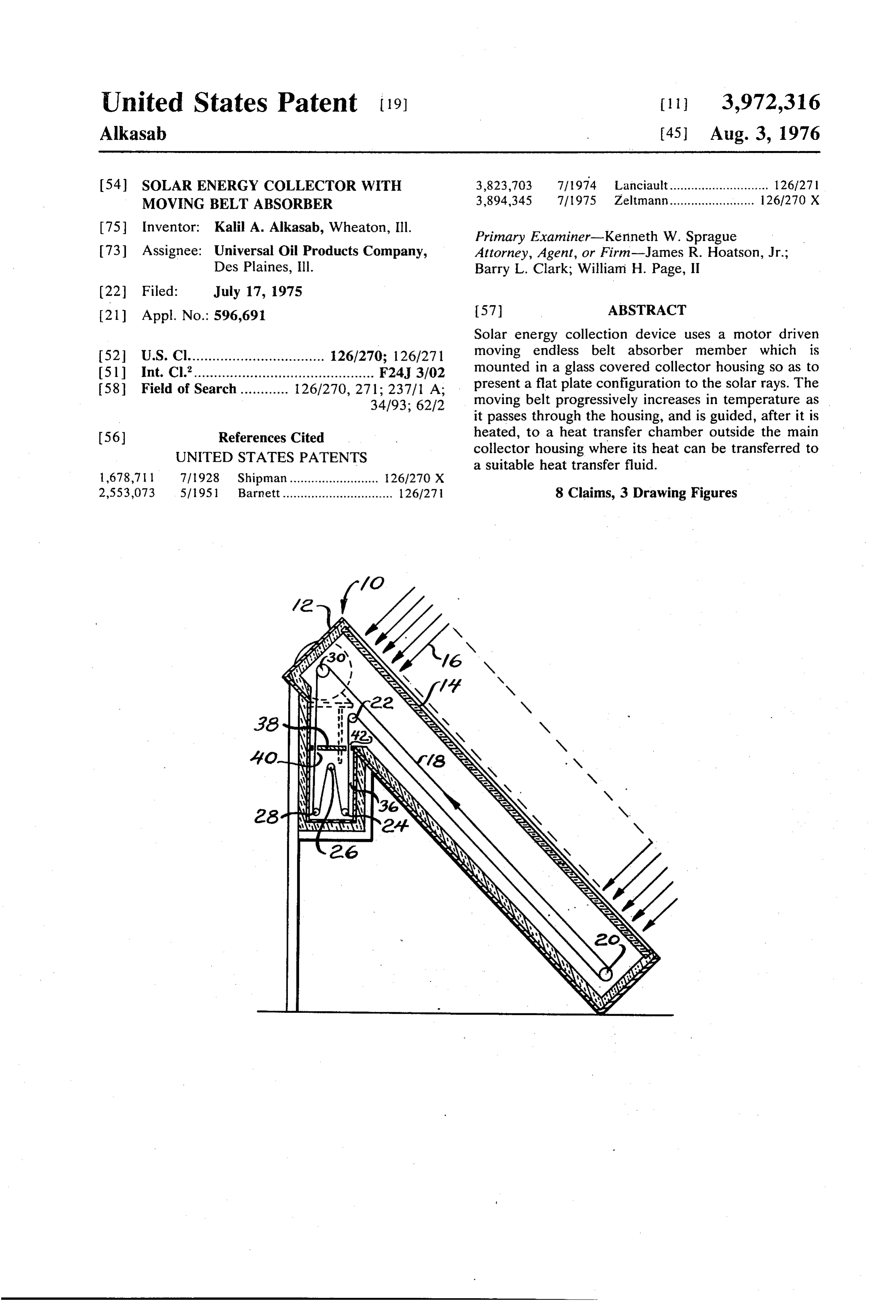
Solar energy collection device uses a motor driven 52 U.S. Cl.................................. 126/270; 126/271 moving endless belt absorber member which is (51) Int. Cl’............................................. F24, 3/02 mounted in a glass covered collector housing so as to 58 Field of Search ............ 126/270, 271; 237/1 A; present a flat plate configuration to the solar rays. The 34/93; 62/2 moving belt progressively increases in temperature as it passes through the housing, and is guided, after it is 56 References Cited heated, to a heat transfer chamber outside the main UNITED STATES PATENTS collector housing where its heat can be transferred to a suitable heat transfer fluid.
1,678,711 7/1928 Shipman......................... 26/270 X 2,553,073 57951 Barnett............................... 126/271 8 Claims, 3 Drawing Figures
Page 2
Drawing sheet — no readable text.
Page 3
though liquid is used as aheat transfer medium, it does
SOLAR ENERGY COLLECTOR WITH MOVING uid not present the freezing problems associated with liq passing through tubes on the surface of a conven
BELT ABSORBER - , , tional flat plate collector since it is contained within an
BACKGROUND OF THE INVENTION s insulated heat exchange compartment in association
The invention relates to solar energy collectors and with wipers aheat storage tank. By the use of appropriate seals particularly to the type of collector commonly referred and the liquid can be substantially completely. to as a flat plate collector wherein a flat, heat:absorbing removed from the belt before it returns to the collector housing. However, some moisture might still be re plate is mounted in an insulated chamber and covered 10 tained by a single or double panel of glass. Such conventional which could produce some condensation on the collectors generally are fairly expensive in that they glass cover plate.
commonly utilize copper panels to which copper tubing BRIEF DESCRIPTION OF THE DRAWINGS is attached, such as by brazing, as an absorbing surface.
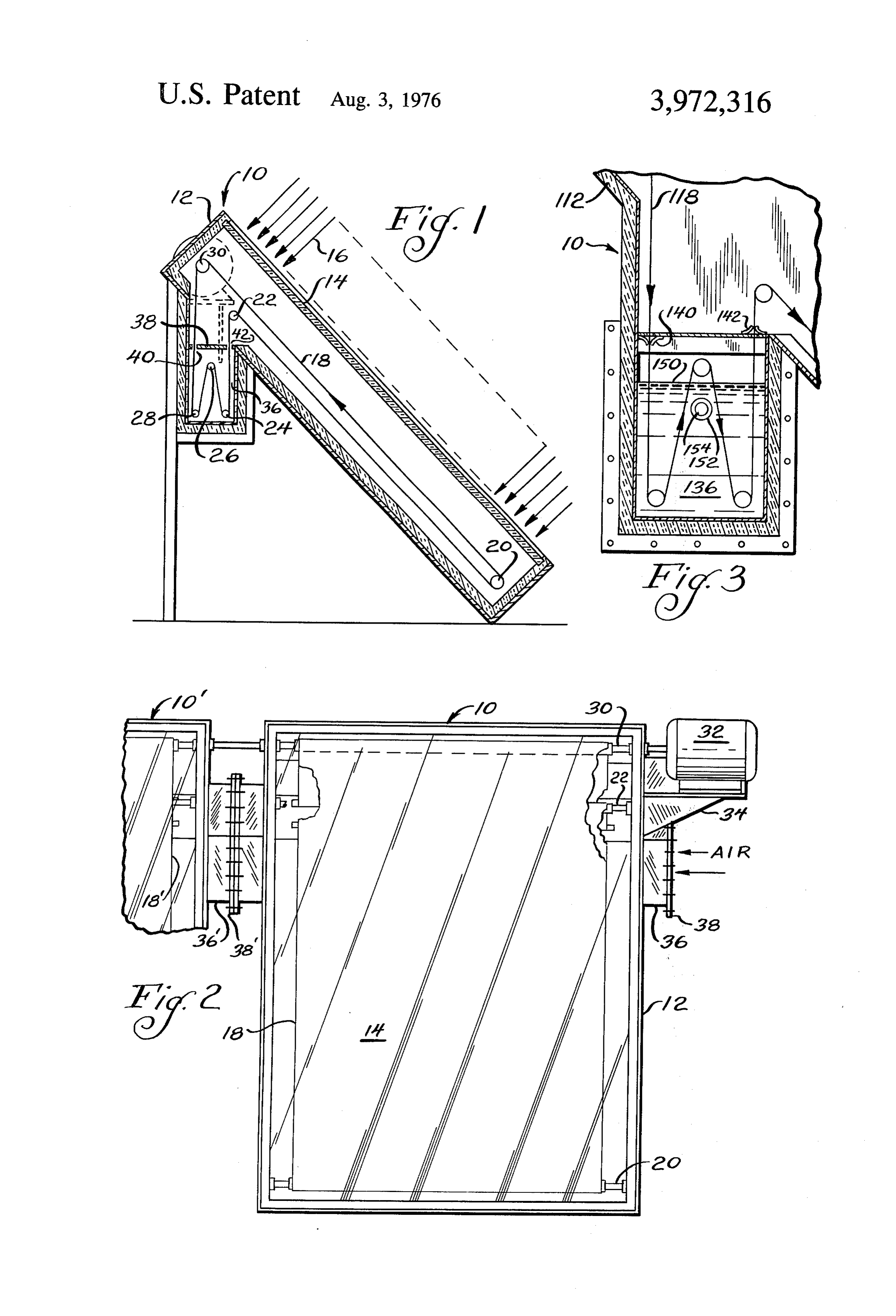
Such collectors are also of limited efficiency since sig 15 FIG. 1 is a sectional side view of the collector; nificant energy is lost through the housing and glass due FIG. 2 is a top view of the collector of FIG. 1; to conduction and re-radiation losses resulting from the FIG. 3 is a fragmentary sectional side view of a modi large temperature differential that exists between the fied collector.
stationary absorber plate and the ambient. A further DESCRIPTION OF THE PREFERRED deficiency of conventional flat plate collectors relates 20 EMBODIMENT to the problems caused by the use of water as a heat transfer fluid. The requirement for pumps is a signifi Referring to FIG. 1, the solar collector indicated at cant expense while freezing and pipe expansion due to 10 comprises a housing 12 which may be formed of a varying temperatures can cause damage to the piping suitable material such as wood or plastic covered with system and portions of a building subjected to any leaks 25 metal. The housing 12 defines a energy collection in the piping. Corrosion of the tubing can also be a chamber 13 which is closed on one side by a panel of problem which can shorten the life of a collector and glass 14 through which solar rays 16 enter the collector produce damage while the collection of moisture on and impinge upon the surface of moving belt member the glass covers can decrease the efficiency of energy 18. The moving belt 18 is formed of fabric reinforced collection. rubber or other suitable material and is preferably 30 black to increase its absorptivity. The belt 18 is guided
SUMMARY around a plurality of guide rollers 20, 22, 24, 26, and It is among the objects of the present invention to 28 and a driving roller 30 which is driven by a motor 32 provide an improved solar energy collector which will mounted on a support bracket 34 attached to the hous be more efficient and less expensive than presently ing 12. A heat exchange compartment 36 is integrally available collectors. 35 attached to the housing 12 and separated from cham These and other objects are achieved by the solar ber 13 by a partition member 38 having apertures 40, energy collector of the present invention which incor 42 which permit the moving belt 18 to move in and out porates an absorber surface in the form of a moving of the compartment 36.
belt. By mounting the moving belt absorber on a plural 40, Preferably, a plurality of units 10,10' are positioned ity of rollers and a driving shaft so that it continually side by side as indicated in FIG. 2 so that the moving carries heat out of the collector housing into a sepa belts 18,18' can be rotated by a single drive roller 30. rated heat exchange comparatment, the heat loss by The heat exchange compartments 36,36' preferably re-radiation to the atmosphere is considerably reduced. include flange portions 38,38' which permit a plurality In a preferred embodiment, the heat transfer fluid of collectors 10,10' to be arranged in series so that the contacting the moving belt absorber within the heat 45. air may be circulated through the compartments 36,36' exchange compartment is air. Although the air must be as indicated by the arrows in FIG. 2. moved, the expense of doing so is considerably less FIG. 3 illustrates a modification of the embodiment than pumping a liquid. By using air, the problems of of FIGS. 1 and 2. In this collector 110, the heat transfer freezing, leaks, and moisture on the cover glass are 50 compartment 136 is closed except for the apertures eliminated. The belt is preferably made of reinforced formed by seals or wipers 140, 142 and is adpated to be rubber or other flexible heat absorbing material. Al filled with liquid 150. The liquid 150 receives the heat though the belt can be driven at a constant speed, it is absorbed by moving belt 118 and transfers it to a circu preferable that the speed be adjustable so that one can lating liquid fowing through the inside 154 of a heat select an appropriate speed between the faster ones 55 exchange tube 152. The seals or wipers 140, 142 help which would produce greater total heat transfer and insulate the heat exchange compatment 136 and also, slower ones which would produce heat transfer at in the case of exit wiper 142, wipe water from the belt higher temperatures. Controls are also provided, of 118 so as to minimize the opportunity for condensation course, to stop the movement of the belt when the on the inside of the glass panel which covers the hous temperature of the absorbing surface is less than a ing 112. If desired, a plurality of units 110 can be posi desired minimum. Appropriate seals between the belt 60. tioned so that tube 152 will pass through each of them. and the heat exchange compartment serve to prevent I claim as my invention.
excessive leakage of air into the collector housing. 1. A solar energy collection apparatus comprising a In a modified form of collector, a liquid such as water housing forming an energy collection chamber, a belt can be used as the heat exchange compartment. The like absorption member mounted for movement within liquid contacts the moving belt and extracts heat there 65 said housing, a plurality of guide members for mount from, which heat can then be transferred to a finned, ing said absorption member in said housing, a heat liquid containing tube immersed in the liquid which will exchanger carried by said housing and located re carry it to a heat storage tank, for example. Even motely from said collection chamber, a plurality of
Page 4
guide members for mounting said absorption member 4. The apparatus of claim 1 wherein said heat ex in said heat exchanger and cooperating with the guide changer contains air as a heat exchanger medium. members in the housing for permitting the absorption 5. The apparatus of claim 1 wherein said heat ex member to continuously travel from the housing to the changer contains liquid as a heat exchange medium. 6. The apparatus of claim 5 wherein heat exchange heat exchanger and back to the housing, and drive tubing is positioned within said liquid heat exchanger means for driving said absorption member. medium.
2. The apparatus of claim 1 wherein a plurality of 7. The apparatus of claim 3 wherein said heat ex said housings are positioned in predetermined relation changers contain air as a heat exchange medium. to each other, said drive means driving all of said ab O 8. The apparatus of claim 7 wherein the energy col Sorption members simultaneously. lection chambers are covered with glass and the heat 3. The apparatus of claim 2 wherein the heat ex exchangers are sealed relative to the collection cham bers to minimize the leakage or air therebetween while changers carried by each of said housings are con permitting passage of said absorption members. nected to each other in heat exchange relation. 15
Provenance
- Collection
- Cited prior art
- Original PDF
- patentimages.storage.googleapis.com →
- Filed
- 1975-07-17
- Pages
- 4
- Method
- pdftotext (the PDF's own text layer) + pdftoppm 300dpi page scans
- Source
- Google Patents bibliographic record
- Granted
- 1976-08-03
- Inventors
- Kalil A. Alkasab; Universal Oil Products Co
- Transcribed from
- patentimages.storage.googleapis.com →