patent · US6062201
Fuel injection control for internal combustion engine
16 May 2000
Page 1 — bibliographic record
United States Patent (19) 11 Patent Number: 6,062,201 Nozawa et al. (45) Date of Patent: May 16, 2000 54 FUEL INJECTION CONTROL FOR FOREIGN PATENT DOCUMENTS
INTERNAL COMBUSTION ENGINE
of OOOO
of OOOO 75 Inventors: Masaei Nozawa, Okazaki; Sigenori 2-188646 Japan . of OOOO
Isomura, Kariya; Yukio Sawada, Anjo; 4-86.351 Japan .
of OOOO
Daiji Isobe, Toyohashi, all of Japan 4303141 Japan .
of OOOO
of OOOO 73 Assignee: Denso Corporation, Kariya-city, Japan 60-184921 Japan . of OOOO
of OOOO 21 Appl. No.: 09/071,498 64-11367 Japan . of OOOO
22 Filed: May 4, 1998 Primary Examiner-Henry C. Yuen 30 Foreign Application Priority Data ASSistant Examiner Hieu T. Vo Attorney, Agent, or Firm Nixon & Vanderhye P.C.
May 13, 1997 JP Japan .................................... 9-122231 57 ABSTRACT May 13, 1997 JP Japan ... 9-122232
Jun. 25, 1997 JP Japan .................................... 9-168890 A fuel injection control System for an engine enhances Mar. 6, 1998 JP Japan .................................. 10-0551SO efficiency for charging Suctioned air into a cylinder Stabilizes 51 Int. Cl." - F02D 41/00 a fuel combustion State. An engine intake pipe is provided 52 U.S. Cl. ........................ 123/478; 123/480; 123/90.16 with an air-assisted injector. Fuel injected by the injector 58 Field of Search ..................................... 123/478,480, flows into a combustion chamber within the cylinder via an 123/486, 90.15, 90.16 intake valve. An ECU controls the injector drive so that injected fuel flows into the cylinder about /3 of the time at 56) References Cited the beginning of the valve opening period. This arrangement
allows a large amount of fuel Supplied into the cylinder to be
Vaporized quickly and completely before the intake value is 4,785,786 11/1988 Nagao et al. ........................... 123/488 closed. At this time, because temperature of air drops due to 5,117,795 6/1992 Ohsuga et al........ ... 123/478 heat of vaporization of the fuel, weight (density) of air 5,427,069 6/1995 Tomisawa et al. .. ... 123/478 Suctioned into the cylinder per unit Volume increases, thus 5,685,276 11/1997 Tanaka et al. .......................... 123/478 enhancing the charging efficiency of Suctioned air. 5,735,248 4/1998 Matsuura et al. ....................... 123/527 5,832,901 11/1998 Yoshida et al. ......................... 123/478 25 Claims, 29 Drawing Sheets
EXHAUST INTAKE
WALWE WALWE
WALWE
LIFT
SION)
FUEL
NFLOW
Z2 INTAKE WALWE
: OPEN
INTAKE
FLOW
SPEED
Page 2
Drawing sheet — no readable text.
Page 3
Drawing sheet — no readable text.
Page 4
Drawing sheet — no readable text.
Page 5
Drawing sheet — no readable text.
Page 6
Drawing sheet — no readable text.
Page 7
Drawing sheet — no readable text.
Page 8
Drawing sheet — no readable text.
Page 9
Drawing sheet — no readable text.
Page 10
Drawing sheet — no readable text.
Page 11
Drawing sheet — no readable text.
Page 12
Drawing sheet — no readable text.
Page 13
Drawing sheet — no readable text.
Page 14
Drawing sheet — no readable text.
Page 15
Drawing sheet — no readable text.
Page 16
Drawing sheet — no readable text.
Page 17
Drawing sheet — no readable text.
Page 18
Drawing sheet — no readable text.
Page 19
Drawing sheet — no readable text.
Page 20
Drawing sheet — no readable text.
Page 21
FIG. 34 MEDIUM
LOAD
LOAD
FIXED FUEL
PRESSURE
SCS FUEL
CD AVERAGING
TONING ISE
FUEL PRESSURE
FOR PROPORTIONING
INFLOW SPEED
FUEL PRESSURE
FOR AVERAGING
|NFLOW SPEED
Page 22
Drawing sheet — no readable text.
Page 23
Drawing sheet — no readable text.
Page 24
Drawing sheet — no readable text.
Page 25
Drawing sheet — no readable text.
Page 26
Drawing sheet — no readable text.
Page 27
INUECTOR
DRIVE CONTROL
DETERMINE 402
INUECTION MODE
LOW TEMP
WARIABLE
DRIVE INUECTOR DRIVE INUECTOR DRIVE INUECTOR
IN FIXED MODE IN WARIABLE MODE IN LOW TEMP MODE
Page 28
Drawing sheet — no readable text.
Page 29
Drawing sheet — no readable text.
Page 30
Drawing sheet — no readable text.
Page 31
FUEL INJECTION CONTROL FOR Suctioned to the engine, the higher the pressure of the fuel INTERNAL COMBUSTION ENGINE (fuel pressure) fed to the injector is increased and Such that the crankshaft angular position for ending injection is
CROSS REFERENCE TO RELATED changed corresponding to engine operating States. APPLICATION However, although this system has allowed stratified fuel This application relates to and incorporates herein by combustion to be realized by injecting fuel almost in the reference Japanese Patent Applications No. 9-122231, later half of the intake Stroke, actually the wetness of the port 9-122232, 9-168890 and 10-55150 filed on May 13, 1997, has increased due to the particle size of the fuel injected and May 13, 1997, Jun. 25, 1997 and Mar. 6, 1998, respectively. Supplied from the injector. That is, combustion is incomplete and no adequate Stratified mixture is realized because the
BACKGROUND OF THE INVENTION average fuel particle size is about 150 to 200um in general, 1. Field of the Invention causing the port to be wet and cylinder to be wet and hardly allowing homogeneous mixture to be provided.
The present invention relates to a fuel injection control
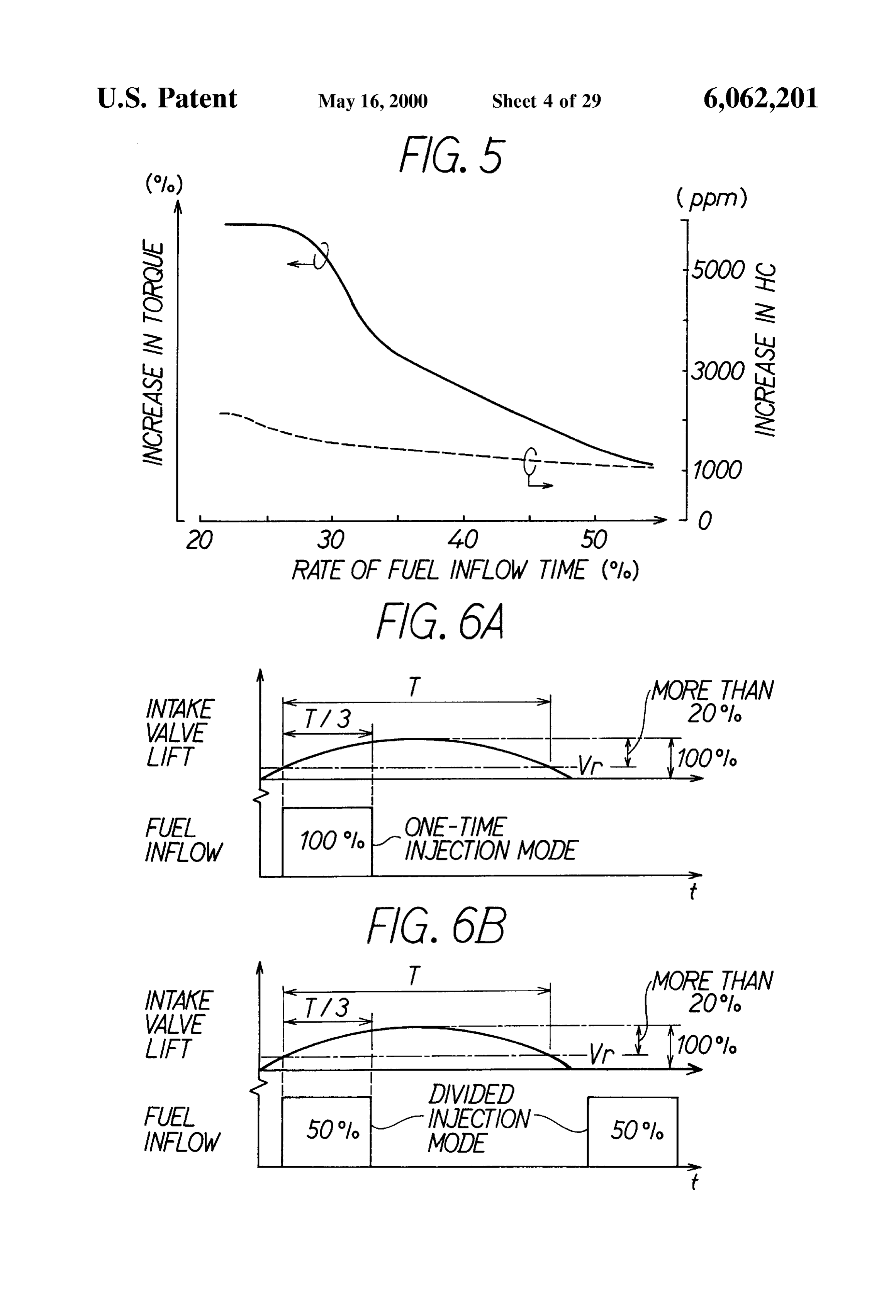
System and method for an internal combustion engine. 15 SUMMARY OF THE INVENTION 2. Description of Related Art It is a primary object of the present invention to provide There is disclosed in Japanese Patent Application Laid a fuel injection control System of an internal combustion Open No. 4-303141 a control system for an internal com engine which enhances efficiency for charging Suctioned air bustion engine. In this System fuel injection end timing is into a cylinder and Stabilizes a fuel combustion State. determined before Starting an intake Stroke or during the It is a Second object of the present invention to provide a intake Stroke in response to timing for completely closing an fuel injection control System of an internal combustion intake valve. Specifically, injection is ended before the Start engine which allows the mixture Suctioned into a cylinder to of the intake Stroke when the timing for completely closing be homogenized and a range in which the fuel consumption the intake valve is earlier than a predetermined discriminat 25 and the air-fuel ratio can be controlled to be expanded. ing timing and is ended during the intake Stroke when the It is a third object of the present invention to provide a fuel Valve closing timing is later than the predetermined dis injection control System of an internal combustion engine criminating timing. Such system allows fuel injection timing which allows the lean limit of the mixture to be extended by to be adequately controlled in response to changes in oper Stratifying the mixture Supplied into the cylinder. ating States of the intake Valve which occur due to changes According to a first aspect of the invention, drive of an in engine load, thus Stabilizing the combustion State and injector is controlled such that the fuel injected by the improving charging efficiency. injector flows into the cylinder within a specific time based However, because the injected fuel continuously flows on intake valve opening timing. Because the inflow of fuel into a cylinder until the later period of the intake stroke (until into the cylinder is finished before the specific timing of the the intake valve closes) in Such system, there remains 35 intake Stroke of the engine, much of the inflow fuel is non-vaporized fuel even when the intake valve is closed. Vaporized quickly and mixing of the vaporized fuel with the Due to that, there is a possibility that the combustion state Suctioned air is accelerated within the valve opening period within the cylinder is worsened and the non-vaporized fuel of the intake valve. That is, vaporization of the fuel Supplied is exhausted as unburnt HC also increasing wetness of the into the cylinder is completed before the intake valve is fuel. Further, because the fuel is not fully vaporized, the heat 40 closed and intake is finished. At this time, because the heat of vaporization has not been used effectively and efficiency of vaporization is taken from the ambient air and tempera for charging Suctioned air or air-fuel ratio mixture is low. ture of air within the cylinder drops when the fuel is Further, in another System disclosed in Japanese Patent vaporized, weight (density) of air Suctioned into the cylinder Application Laid-Open No. 3-950, fuel injection amount is per unit volume increases. AS a result, charging efficiency of increased/decreased in proportion to an increase/decrease of 45 the Suction air may be enhanced and the combustion State of an air amount Suctioned to the cylinder So that the air-fuel the fuel may be stabilized. Further, it allows more air to be mixing ratio (air-fuel ratio) of the mixture Suctioned into the Suctioned and output torque of the engine to be improved. cylinder is always fixed with respect to crank angle within According to a Second aspect of the invention, the drive the intake Stroke. This arrangement allows the distribution of of an injector is controlled Such that fuel inflows into a the mixture within the cylinder to be homogenized, thus 50 cylinder within the period of an intake Stroke during which Stabilizing combustion. a flow speed of the Suctioned air exceeds a predetermined However, because the mixture is Suctioned into the cyl value by controlling the amount of fuel Supplied into the inder during the whole period of the intake Stroke during cylinder per unit time pursuant to the flow speed of the air which the intake valve is opened in this System, the mixture Suctioned into the cylinder. The fuel is introduced to the is Suctioned into the cylinder even during a period in which 55 cylinder by being carried on the air whose intake flow speed intake flow speed is very low. In Such a case, the mixture is is relatively fast by controlling the amount of fuel Supplied not fully homogenized and favorable combustion cannot be into the cylinder per unit time pursuant to the intake flow realized. As a result, the control of the fuel injection in a lean Speed and by flowing the fuel injected by the injector into the air-fuel ratio range aiming at the reduction of fuel consump cylinder in the intake Stroke in which the intake flow speed tion and of NOx, i.e., the lean-burn control, has not been able 60 exceeds the predetermined value. The mixture composed of to be realized effectively. the fuel and the air is mixed homogeneously within the Still more, in another System disclosed in Japanese Patent cylinder. As a result, the homogenization of the mixture Application Laid-Open NOS. 60-11652 and 60-122239, Suctioned into the cylinder may be realized, the fuel may be Stratified fuel combustion is carried out by putting timing for burned Stably and the range for controlling the fuel con injecting fuel by the injector (fuel injection valve) almost at 65 Sumption and air-fuel ratio may be expanded. Further, the the later half of an intake stroke. Further, in order to suitably homogenization of the mixture allows the control of fuel realize Stratified fuel combustion, the more air amount injection in the lean air-fuel ratio range (lean burn control)
Page 32
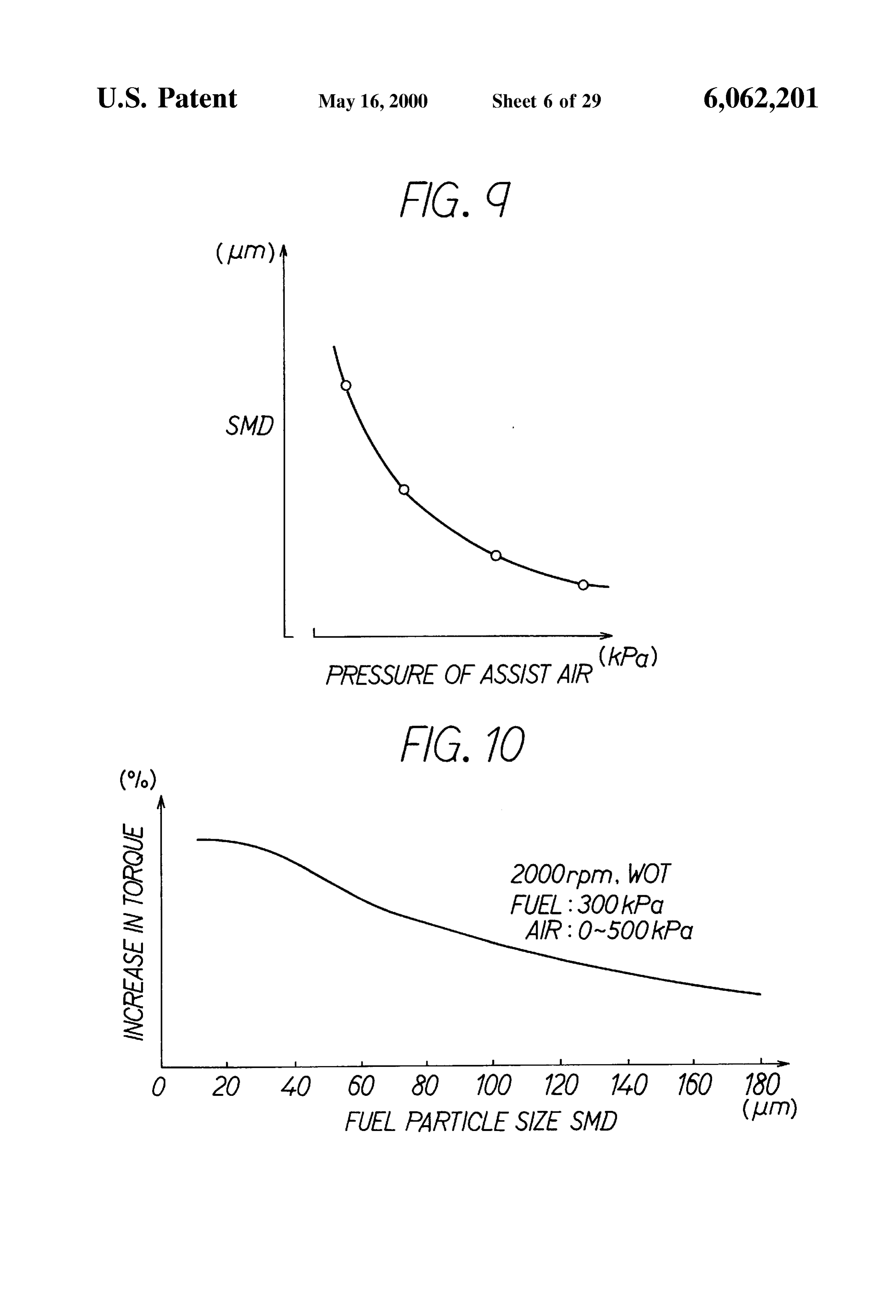
to be stably realized and NOx within emission gas to be FIG. 9 is a graph showing a relationship between pressure reduced in the lean burn control. of pressurized air of the injector and a fuel particle size According to a third aspect of the present invention, the SMD;
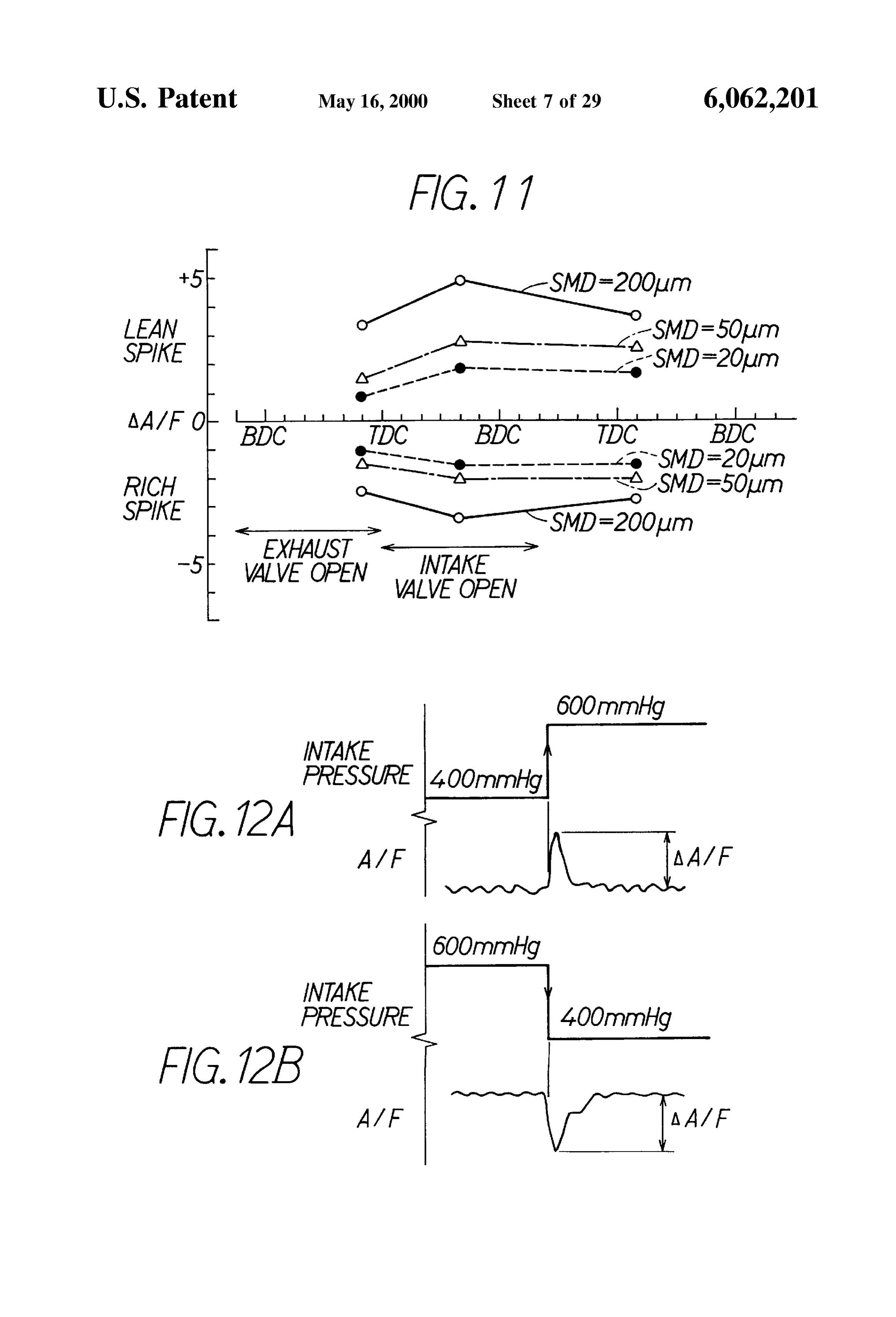
particle size of fuel injected by the injector is atomized to 70 FIG. 10 is a graph showing a relationship between the fuel tim or leSS and the drive of the injector is controlled Such that particle size SMD and the increase of torque; the later the intake Stroke, the more an amount of fuel FIG. 11 is a graph showing a relationship between injec Supplied into the cylinder per unit time is increased. The tion ending timing and a difference AA/F of air-fuel ratio per atomization of fuel is achieved by: controlling preSSure of fuel particle size;
air fed to the injector by using an air-assisted injector; FIGS. 12A and 12B are charts showing lean spike and rich injecting the fuel Sprayed by the injector toward the bevel Spike of the air-fuel ratio during transient operations, portion of the high temperature intake valve; or using a multi-hole type (e.g., 12-hole type) injector. FIG. 13 is a flow chart showing a routine for calculating According to this arrangement, the injector is driven TAU;
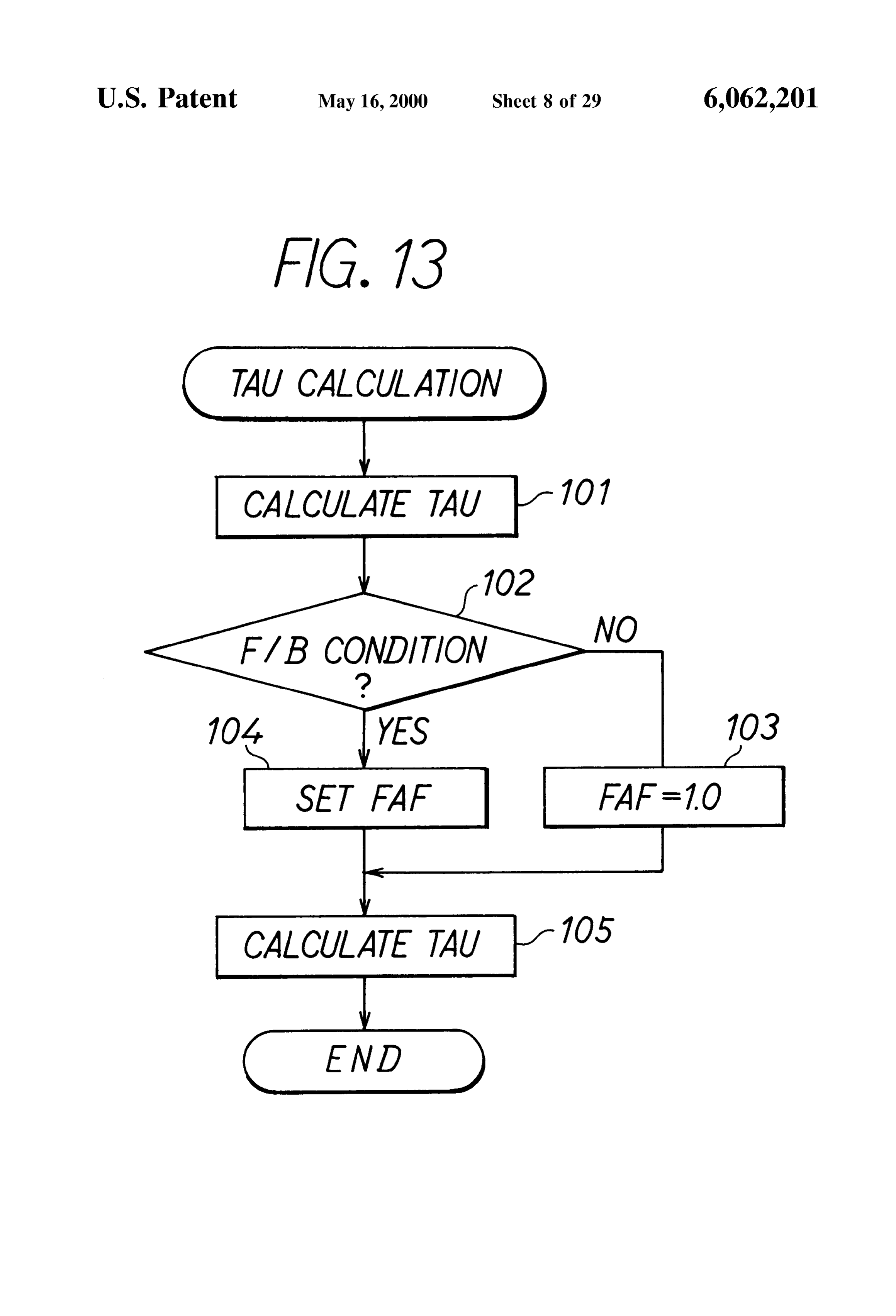
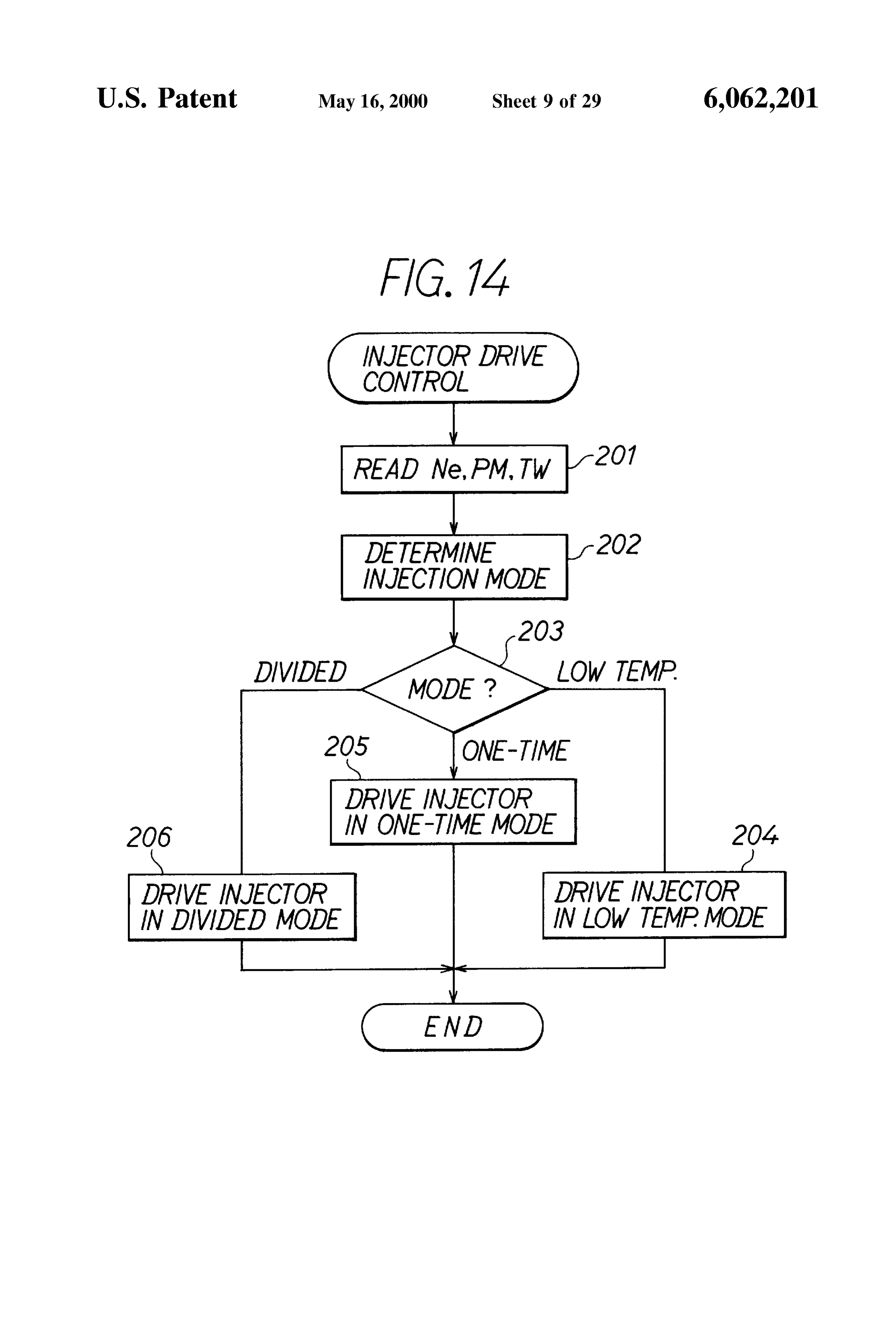
corresponding to the period of the intake Stroke which 15 FIG. 14 is a flow chart showing a routine for controlling follows when the intake valve is opened and the fuel injected drive of the injector;
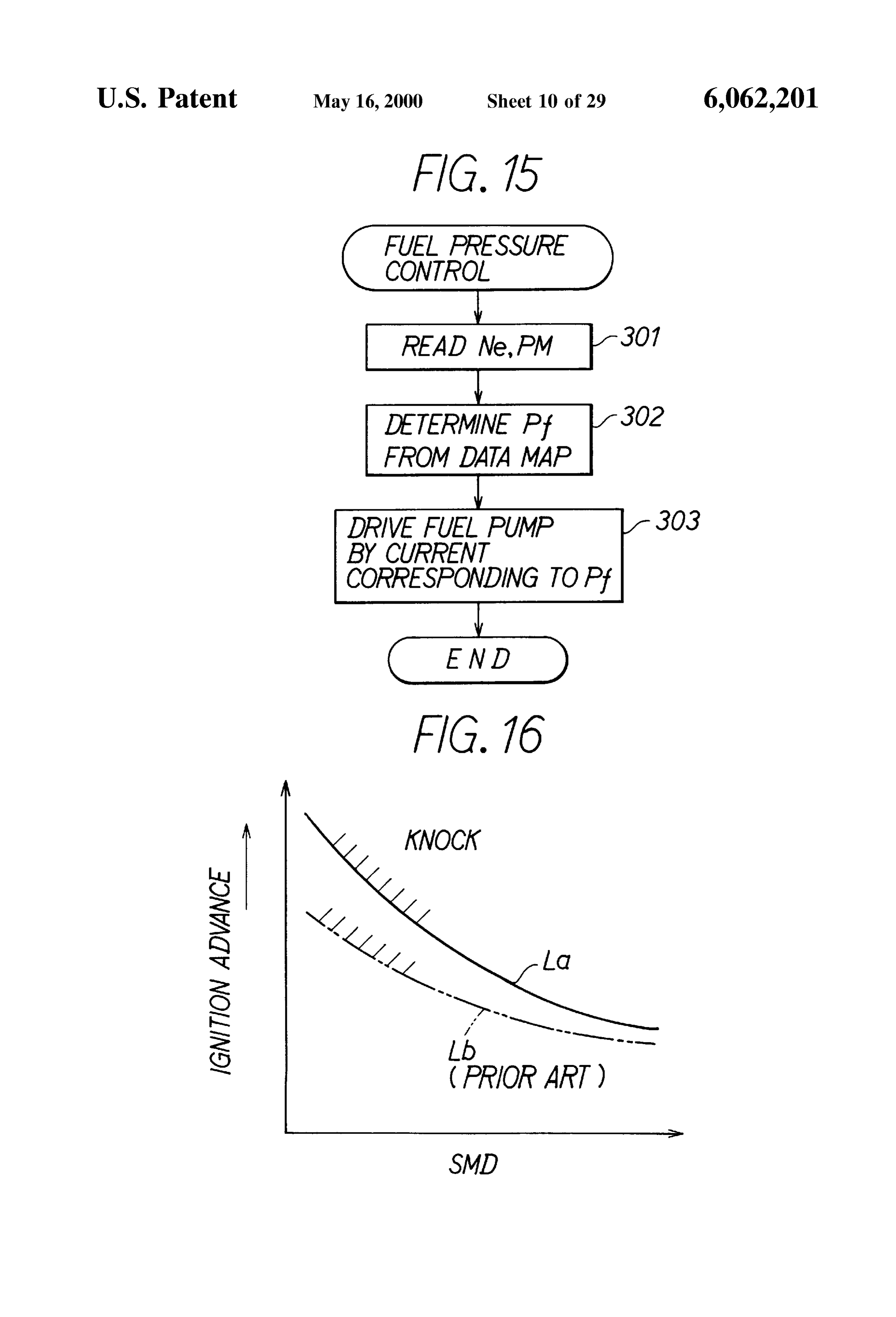
by the injector is Suctioned into the cylinder (combustion FIG. 15 is a flow chart showing a routine for controlling chamber) after being injected to an intake port of the internal fuel preSSure, combustion engine. At this time, because the later the intake FIG. 16 is a graph showing a relationship between a fuel stroke, the more the amount of fuel inflow to the cylinder per particle size and a knock limit;
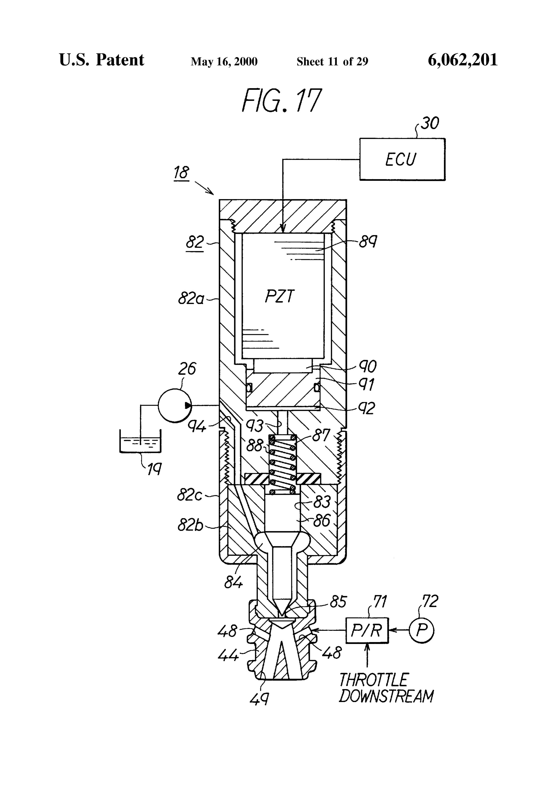
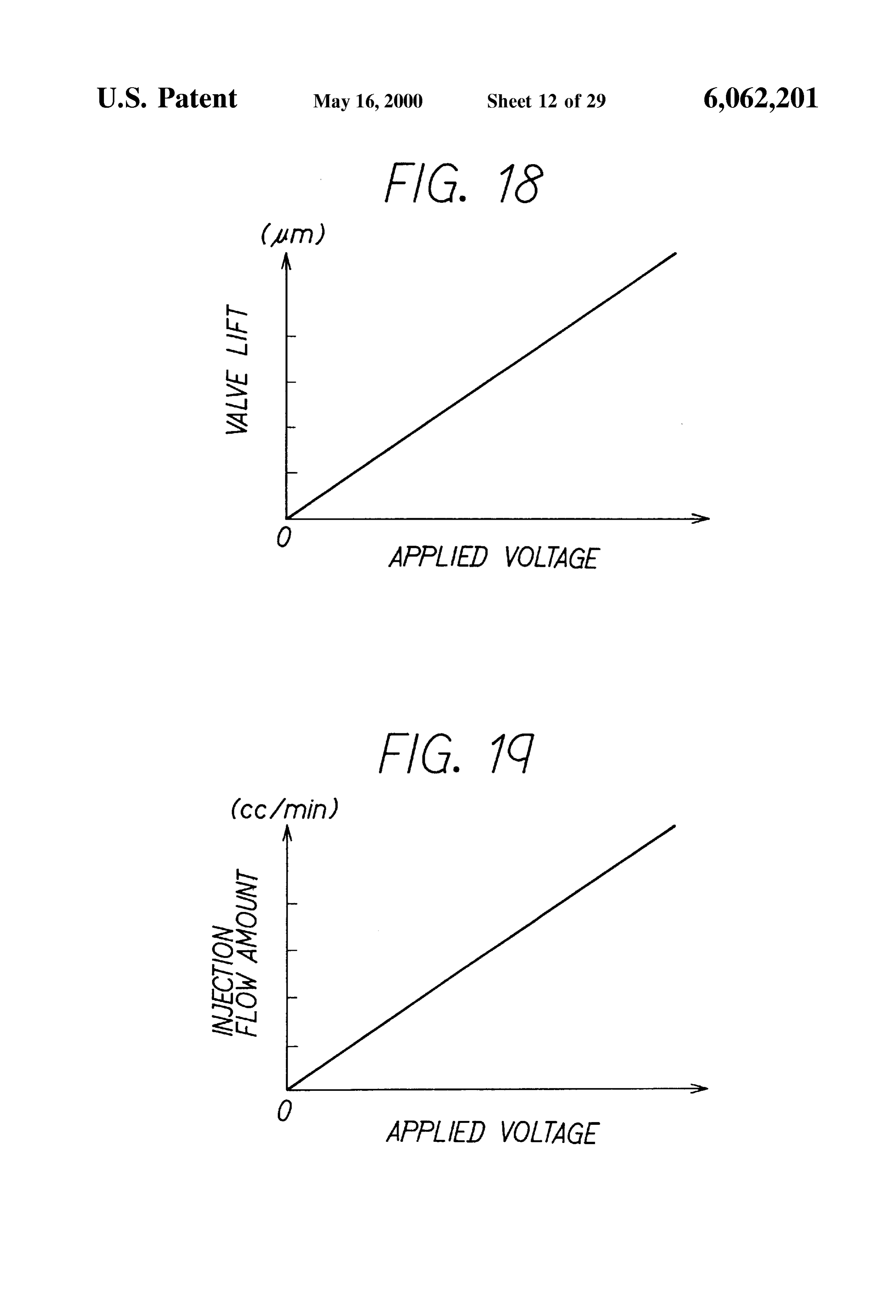
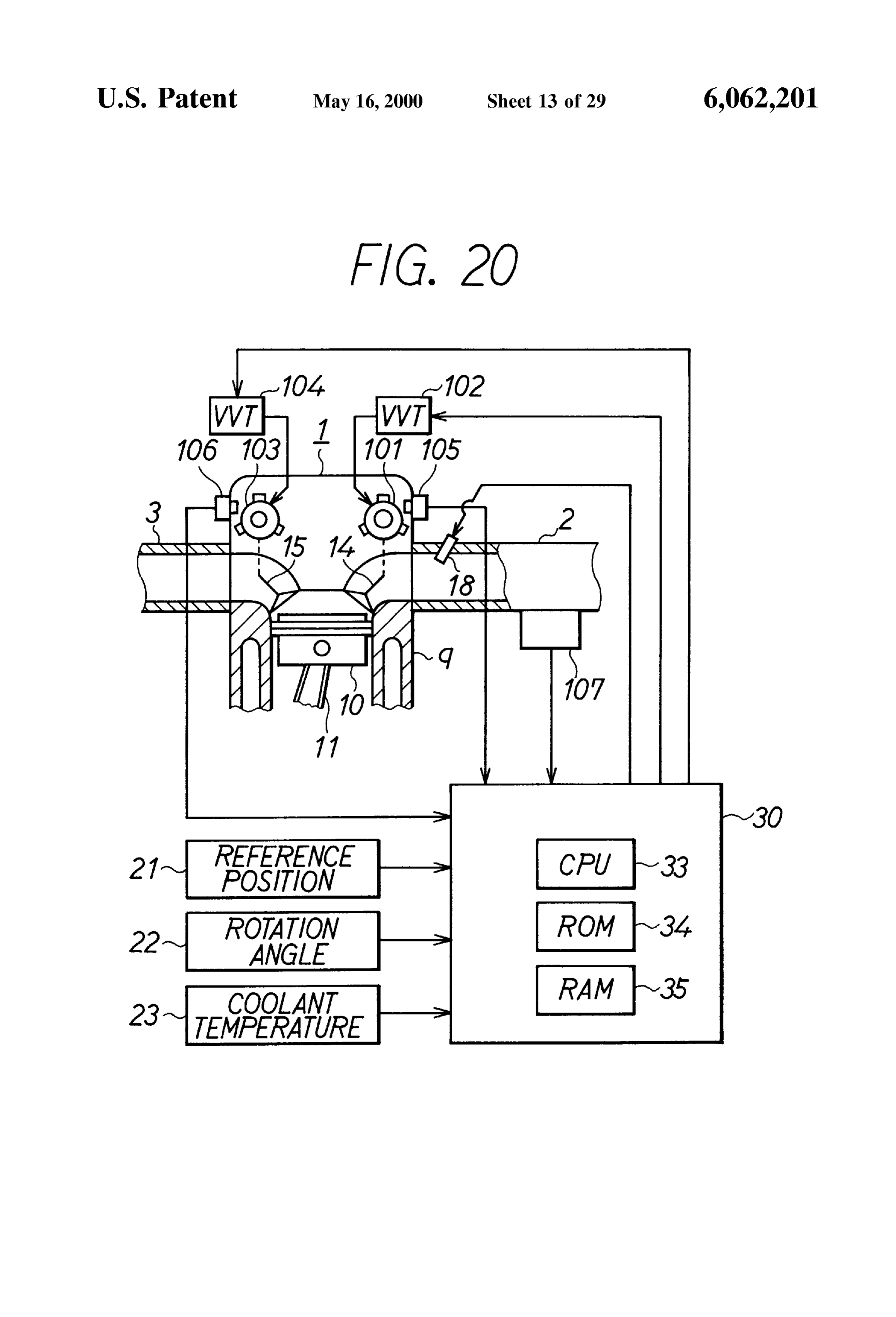
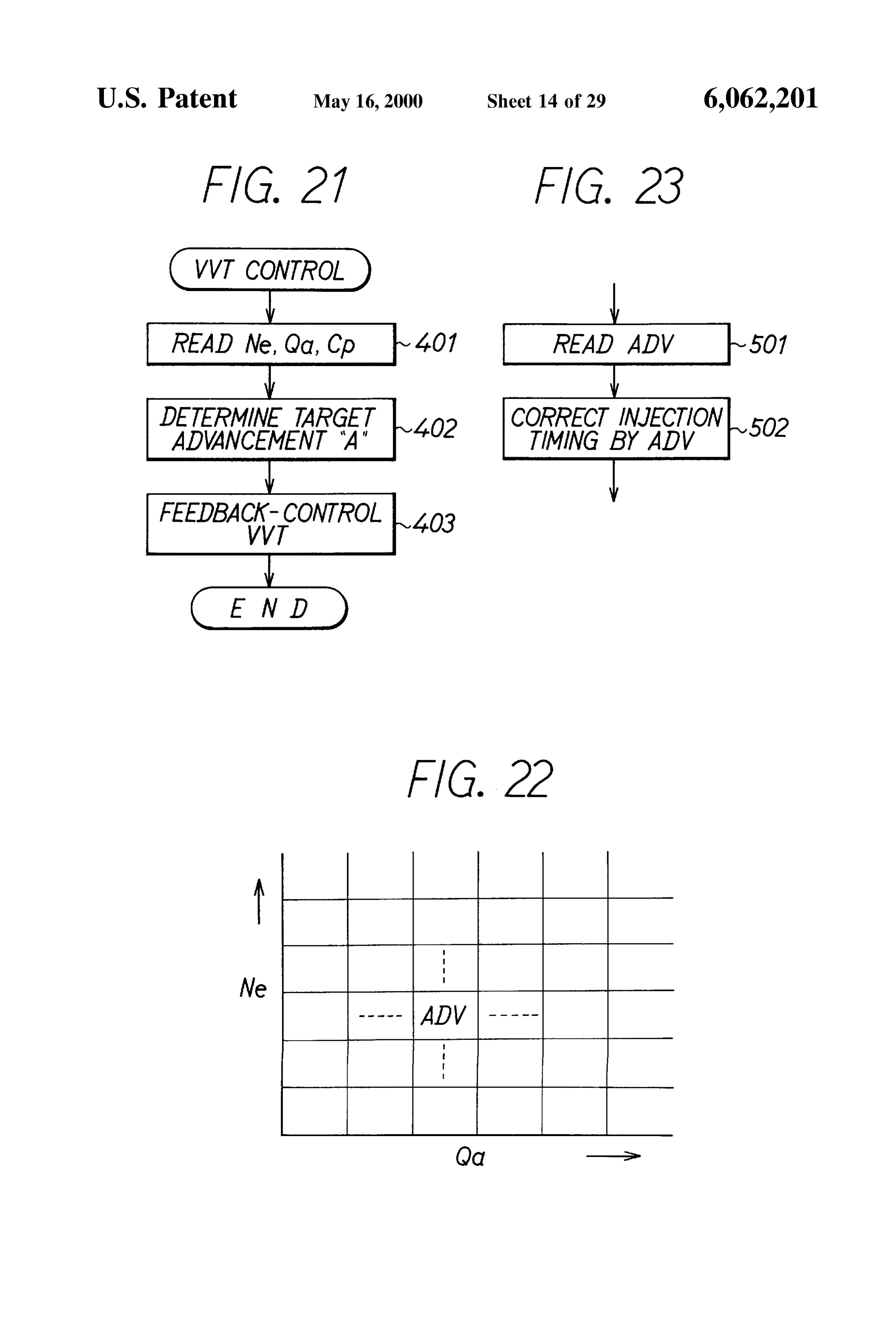
unit time increases, a large amount of fuel is Suctioned just FIG. 17 is a section view showing a piezo-driven injector before the intake valve is closed. Accordingly, Stratified according to a first modification of the first embodiment; mixture may be formed within the cylinder and the com FIG. 18 is a graph showing a relationship between Voltage bustion State may be Stabilized even in the lean air-fuel ratio applied to a piezoelectric Stack and a lift of a valve; range. More concretely, an atmosphere having an air-fuel ratio enough for combustion is provided around an ignition 25 FIG. 19 is a graph showing a relationship between Voltage plug and the Stable combustion may be realized even if the applied to the piezoelectric Stack and an injection flow atmosphere is lean as a whole. Further, because the fuel amount, injected by the injector is atomized to about 70 um or less, FIG. 20 is a schematic view showing a fuel injection Vaporization of the fuel within the cylinder is accelerated, control System of an engine according to a Second modifi thus Suppressing the trouble which has happened in the prior cation of the first embodiment;
art System Such as incomplete burning caused by the cylin FIG. 21 is a flow chart showing a routine for controlling der wet. VVT.
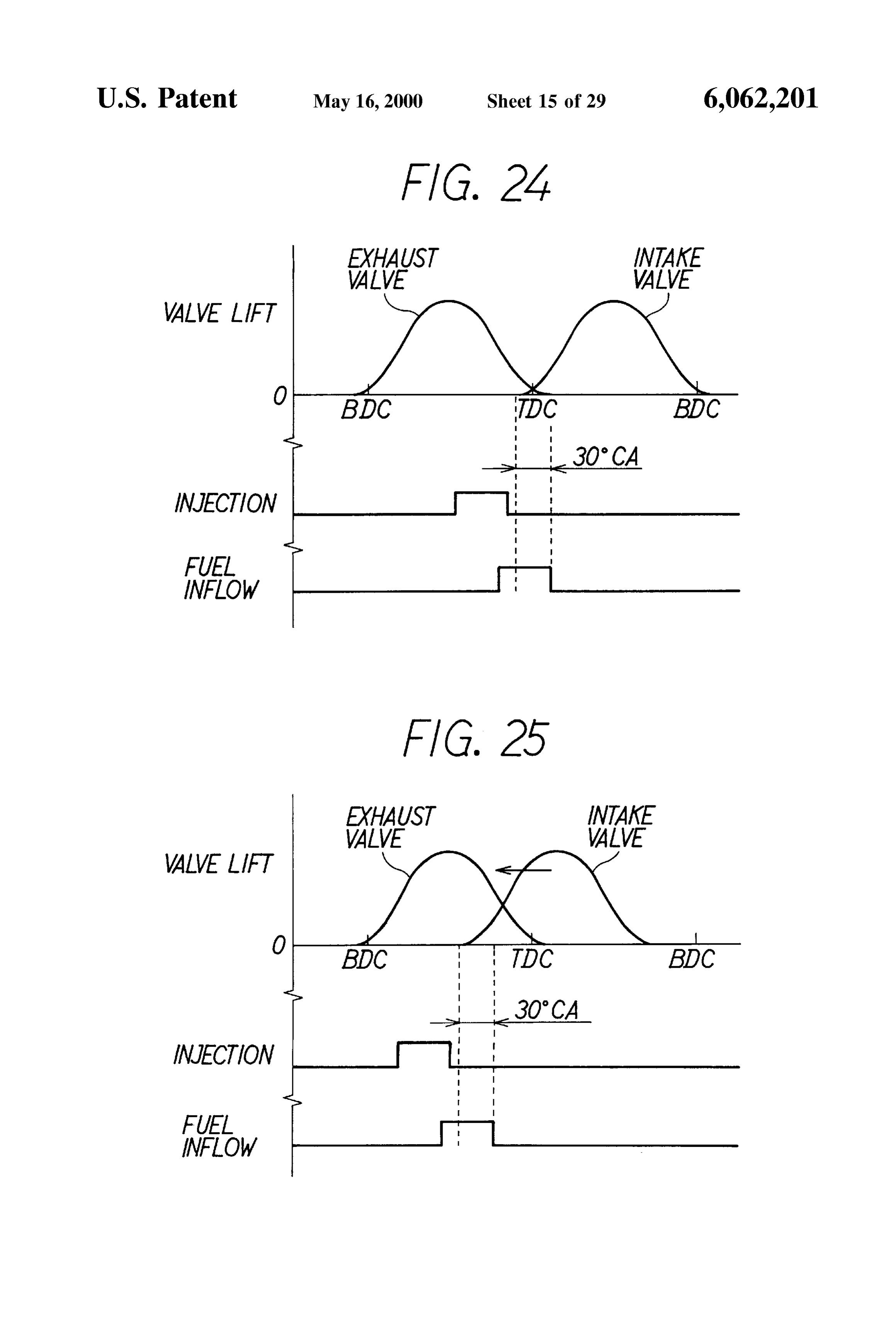
Thus, the third aspect of the invention allows the strati FIG. 22 is a graph showing an advancement map; fication of the mixture supplied into the cylinder to be 35 FIG. 23 is a flow chart showing a part of the routine for realized and in its turn, the lean limit of the mixture to be controlling drive of the injector; extended and the internal combustion engine to be operated FIG.24 is a time chart showing an operation of the Second in a low fuel consumption range. It is noted that the optimum modification;
range of the average particle size SMD of the injected fuel FIG. 25 is a time chart showing the operation of the is 10 to 30 lum. 40 Second modification;
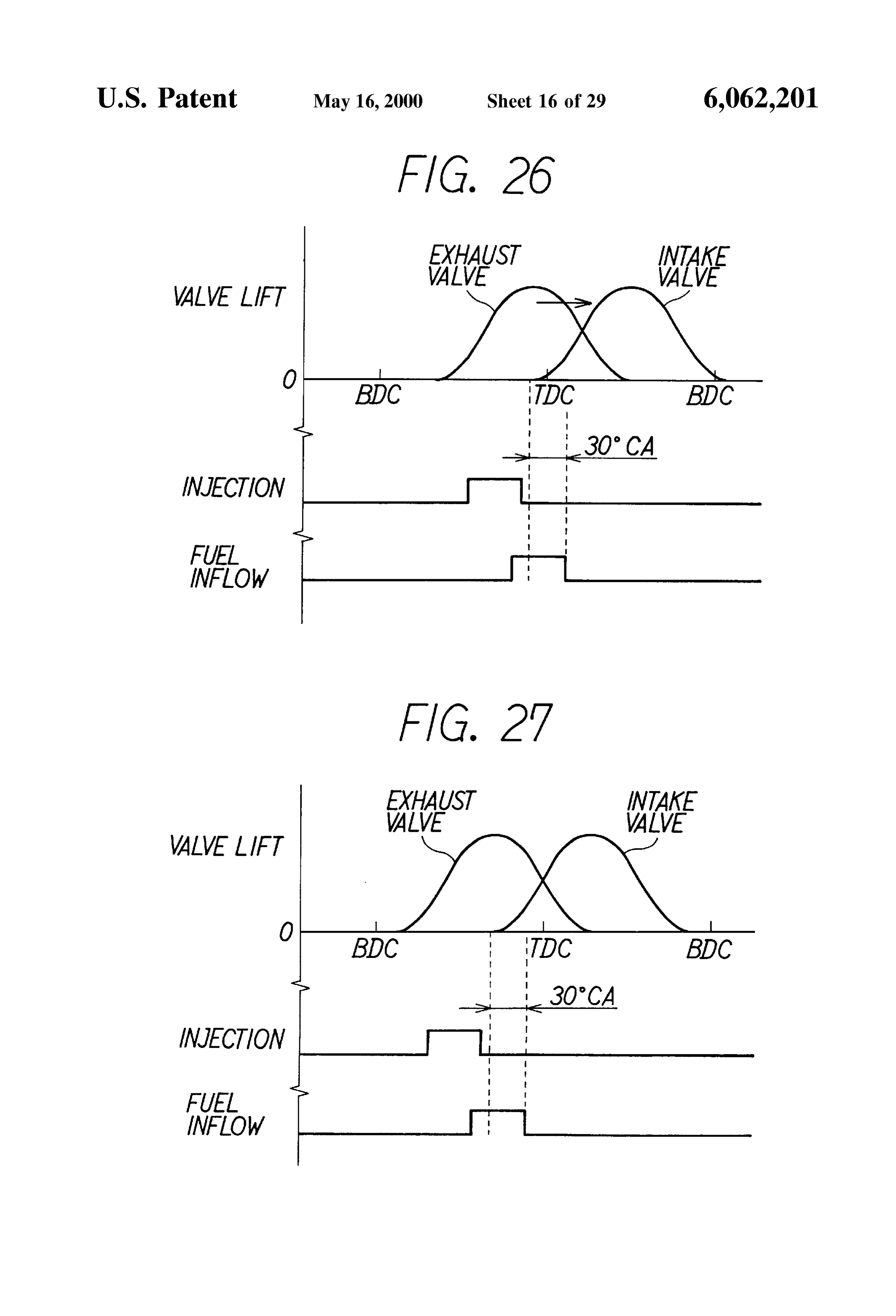
BRIEF DESCRIPTION OF THE DRAWINGS FIG. 26 is a time chart showing the operation of the The Specific nature of the invention, as well as other Second modification;
objects, uses and advantages thereof, will clearly appear FIG. 27 is a time chart showing the operation of the from the following description and from the accompanying Second modification;
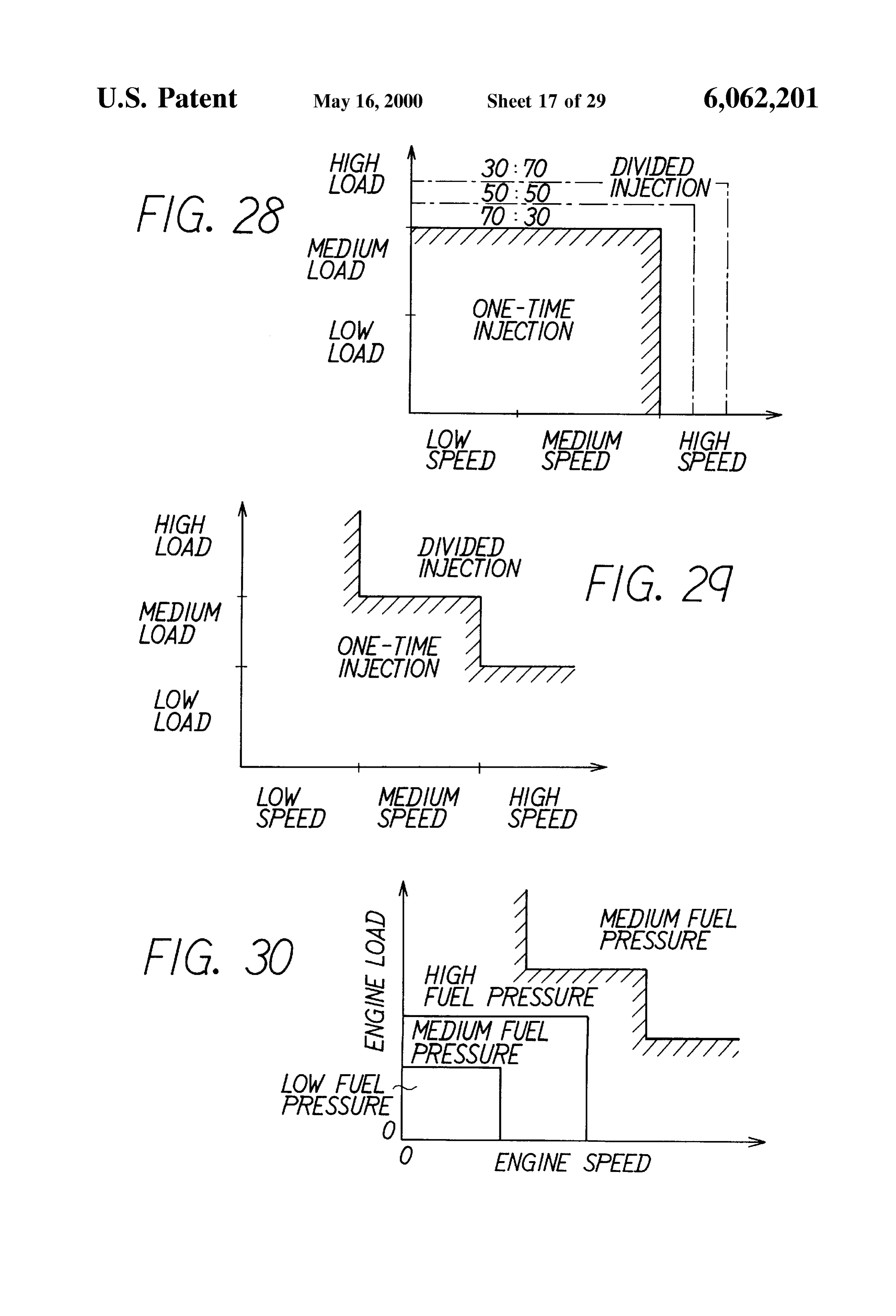
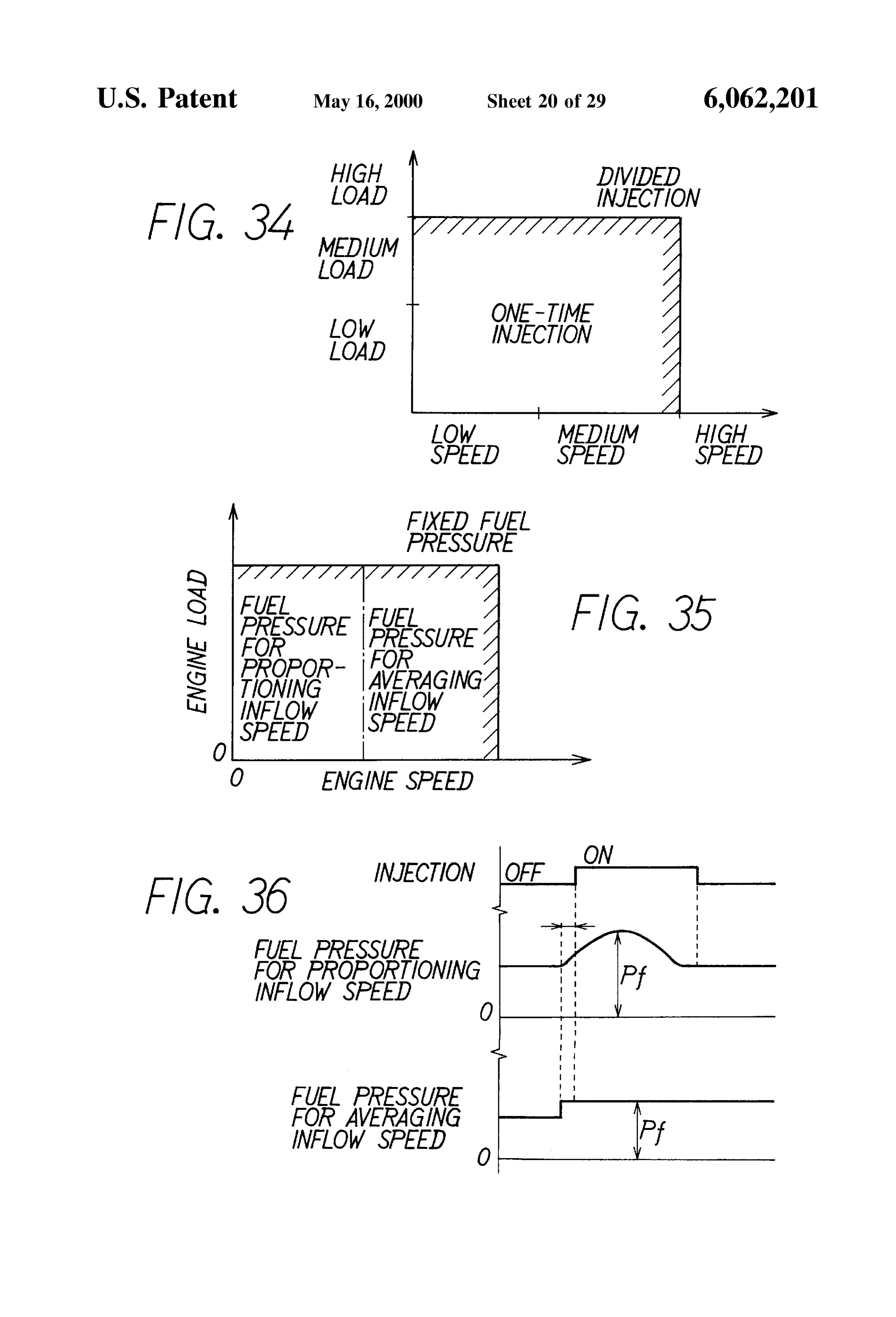
drawings in which like numerals refer to like parts. In the 45 FIG. 28 is a map showing a one-time injection domain drawings: and a divided injection domain corresponding to the engine FIG. 1 is a Schematic view showing a fuel injection operating State according to another modification of the first control System of an engine according to a first embodiment embodiment;
of the present invention; FIG. 29 is a map showing a one-time injection domain FIG. 2 is a Section view showing an air-assisted injector 50 and a divided injection domain corresponding to the engine in detail; operating States according to a still other modification of the FIG. 3 is a time chart showing valve lifts of intake and first embodiment;
exhaust valves when opened, fuel injection timing of the FIG. 30 is a map showing a one-time injection domain injector and a change of intake flow Speed when the intake 55 and a divided injection domain corresponding to the engine Valve is opened; operating States according to a different modification of the FIGS. 4A through 4C are schematic views showing fuel first embodiment;
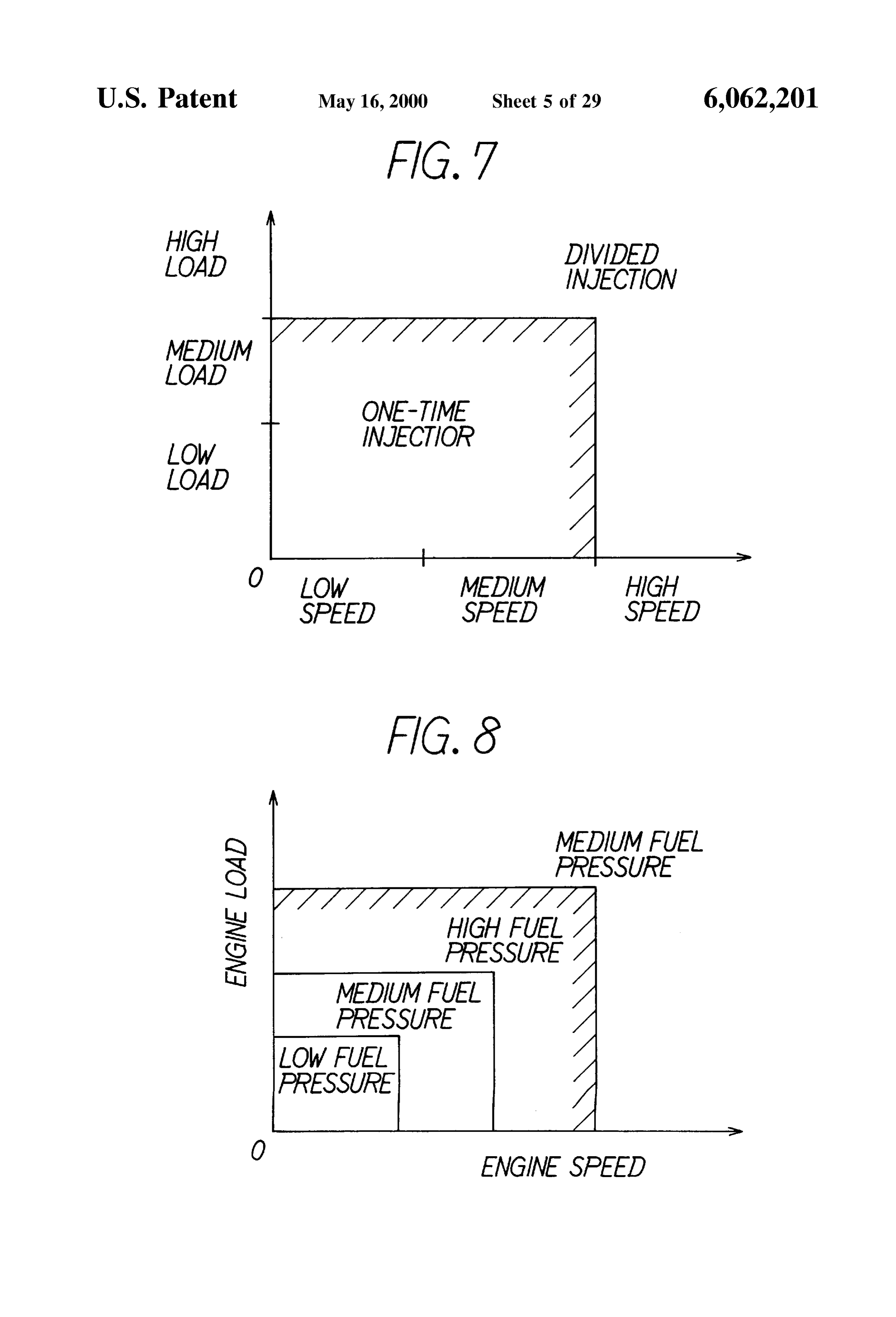
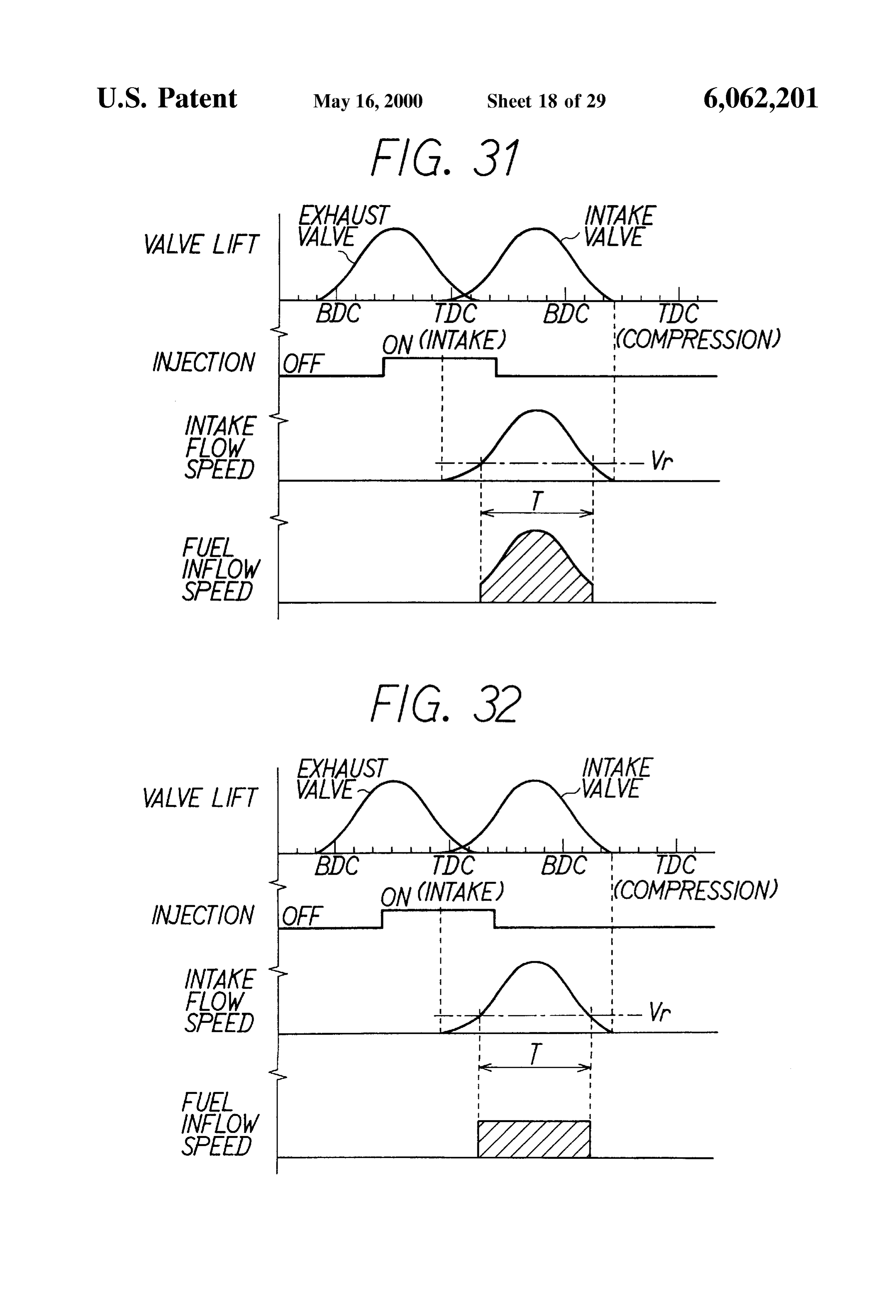
inflow into a cylinder according to the present embodiment; FIG. 31 is a time chart showing valve lifts of intake and FIG. 5 is a graph showing a relationship between a rate of exhaust valves when opened, fuel injection timing of the fuel inflow time and an increase of torque; 60 injector, a change of the intake flow Speed when the intake FIGS. 6A and 6B are time charts showing a one-time Valve is opened and a fuel inflow speed of the fuel Supplied injection mode and a divided injection mode, into the cylinder in a process of proportioning the fuel inflow FIG. 7 is a map showing the one-time injection domain Speed according to a Second embodiment;
and the divided injection domain corresponding to engine FIG. 32 is a time chart showing valve lifts of intake and operating States, 65 exhaust valves when they are opened, fuel injection timing FIG. 8 is a map showing fuel pressure domains corre of the injector, a change of the intake flow speed when the Sponding to the engine operating States, intake valve is opened and a fuel inflow speed of the fuel
Page 33
S 6
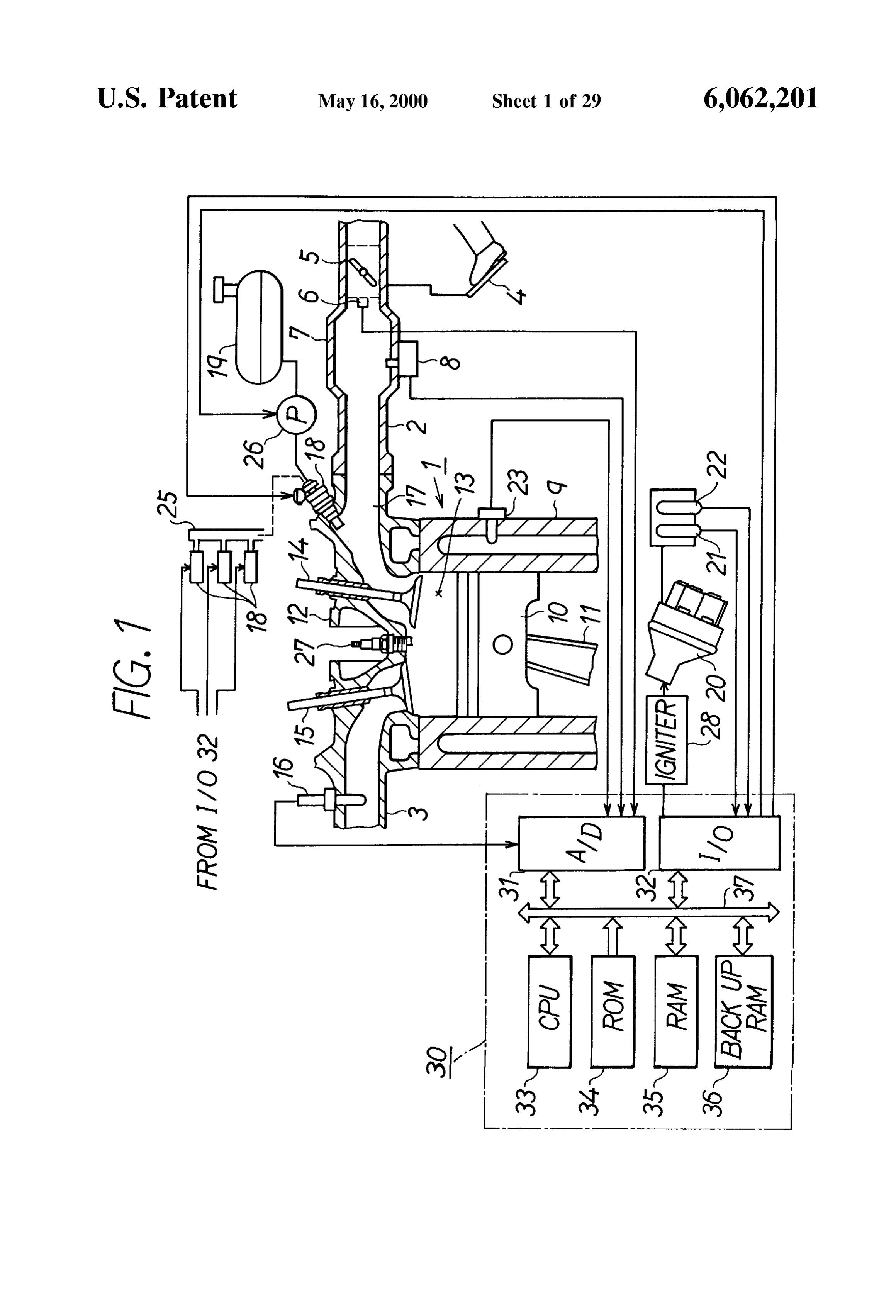
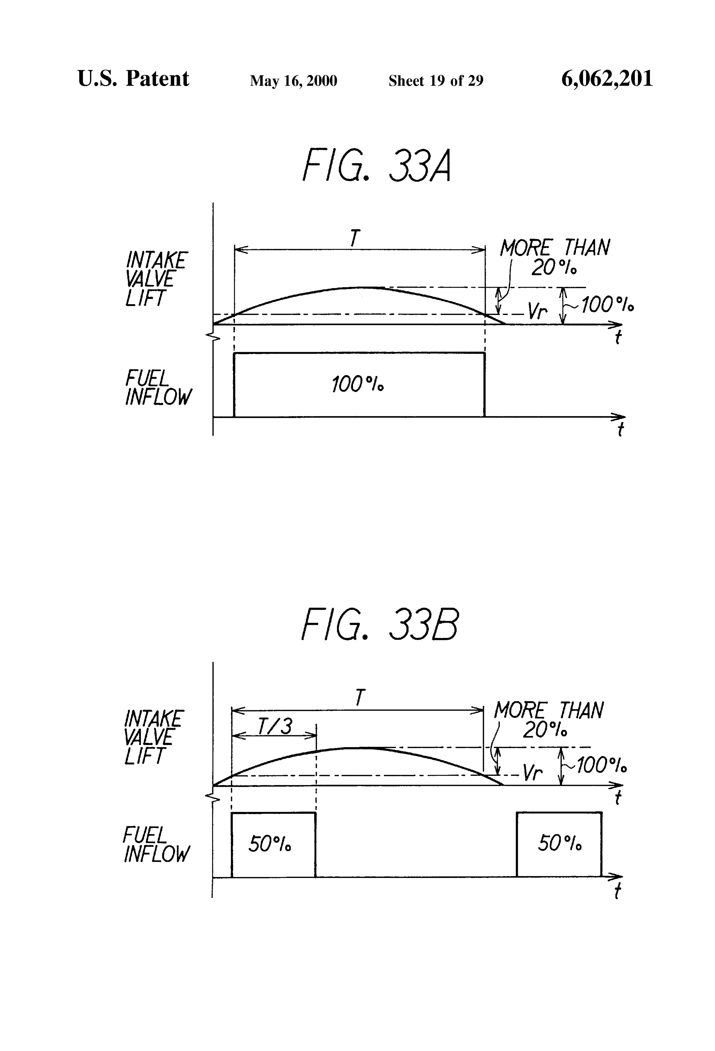
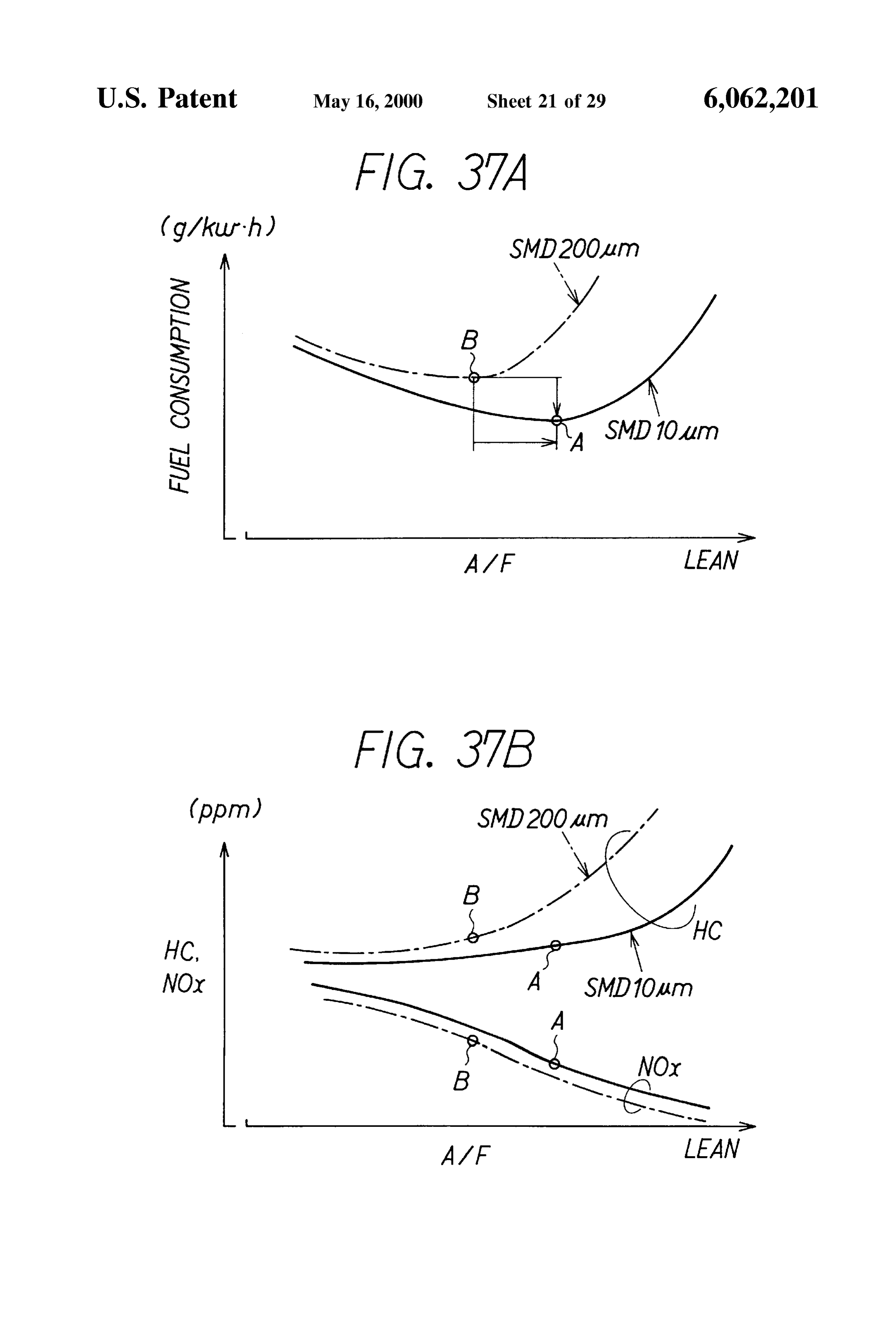
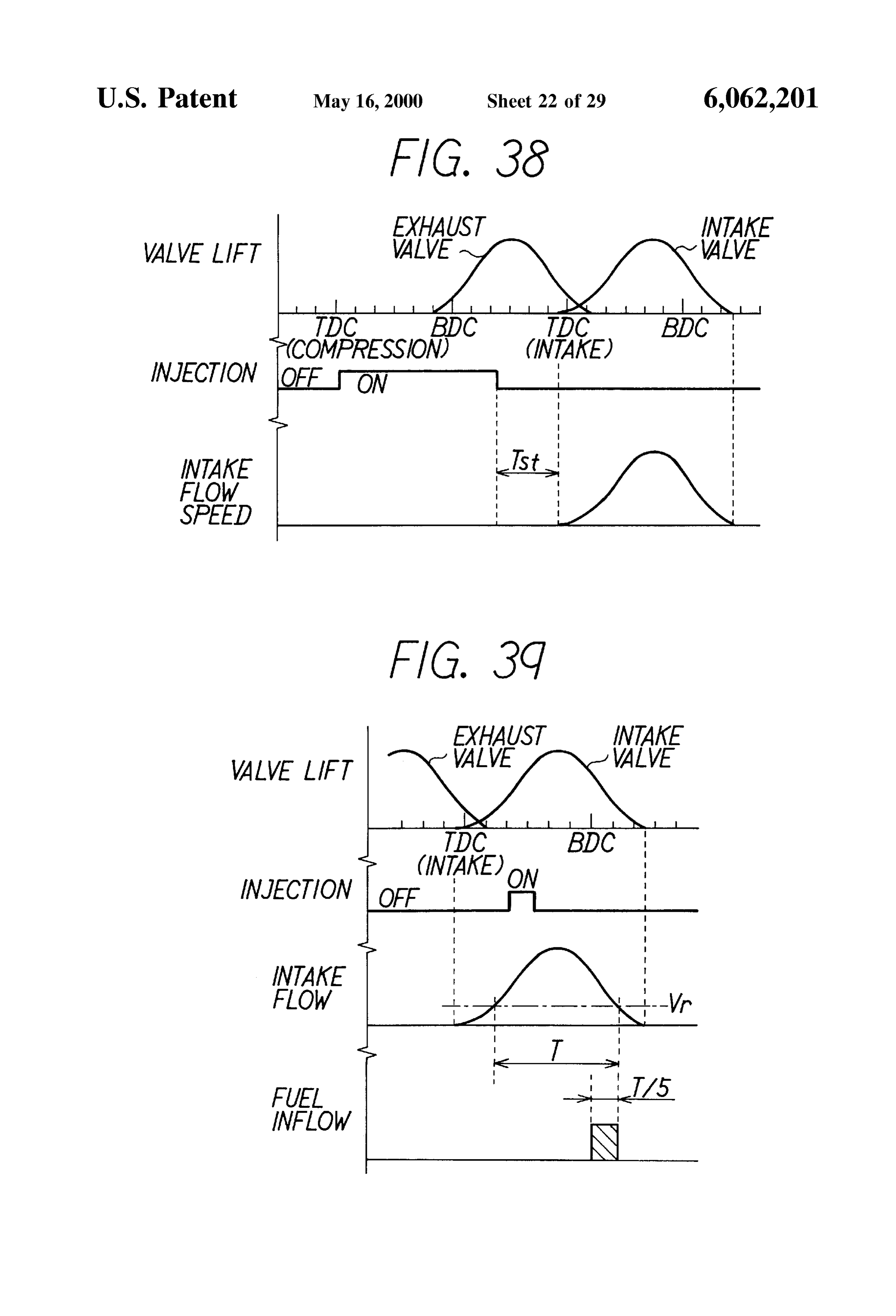
Supplied into the cylinder in a process of averaging the fuel a throttle valve 5 which is interlocked with an accelerator inflow speed according to the Second embodiment; pedal 4 So that its opening angle is detected by a throttle FIGS. 33A and 33B are time charts showing the one-time opening angle Sensor 6. An intake pressure Sensor 8 is injection mode and the divided injection mode, disposed on a Surge tank 7 of the intake pipe 2. FIG. 34 is a map showing a one-time injection domain A piston 10 which reciprocates in a cylinder 9, i.e., the and a divided injection domain corresponding to engine cylinder of the engine 1, and is connected to a crankshaft operating States, (not shown) via a connecting rod 11. A combustion chamber FIG. 35 is a map showing fuel pressure domains corre 13 which is defined by the cylinder 9 and a cylinder head 12 Sponding to engine operating States, is provided the piston 10. The combustion chamber 13 FIG. 36 is a time chart showing fuel injection timing of via communicates with the intake pipe 2 and the exhaust pipe 3 the injector and fuel pressure control; an intake valve 14 and an exhaust valve 15, respectively. An A/F (air-fuel ratio) sensor 16 of a limiting current type
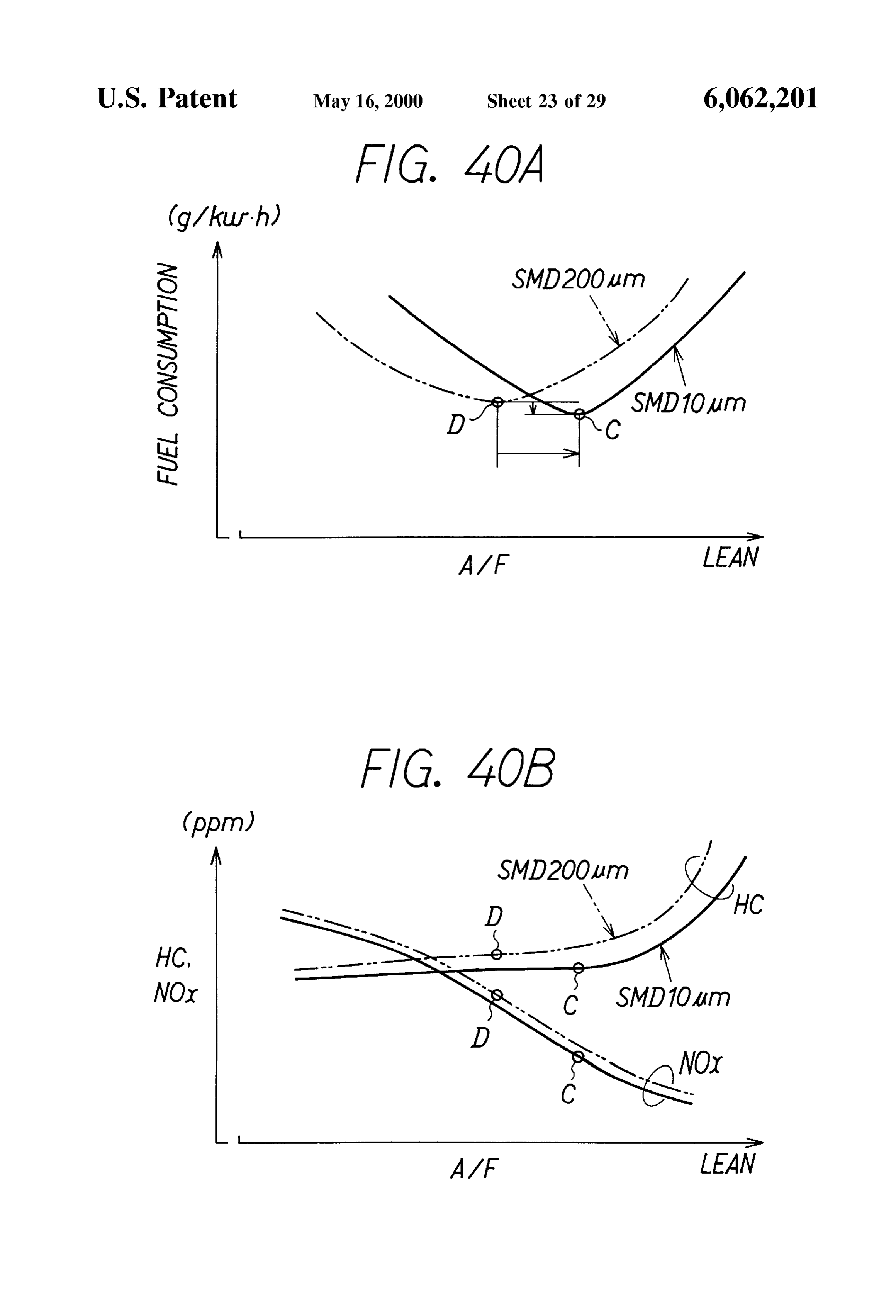
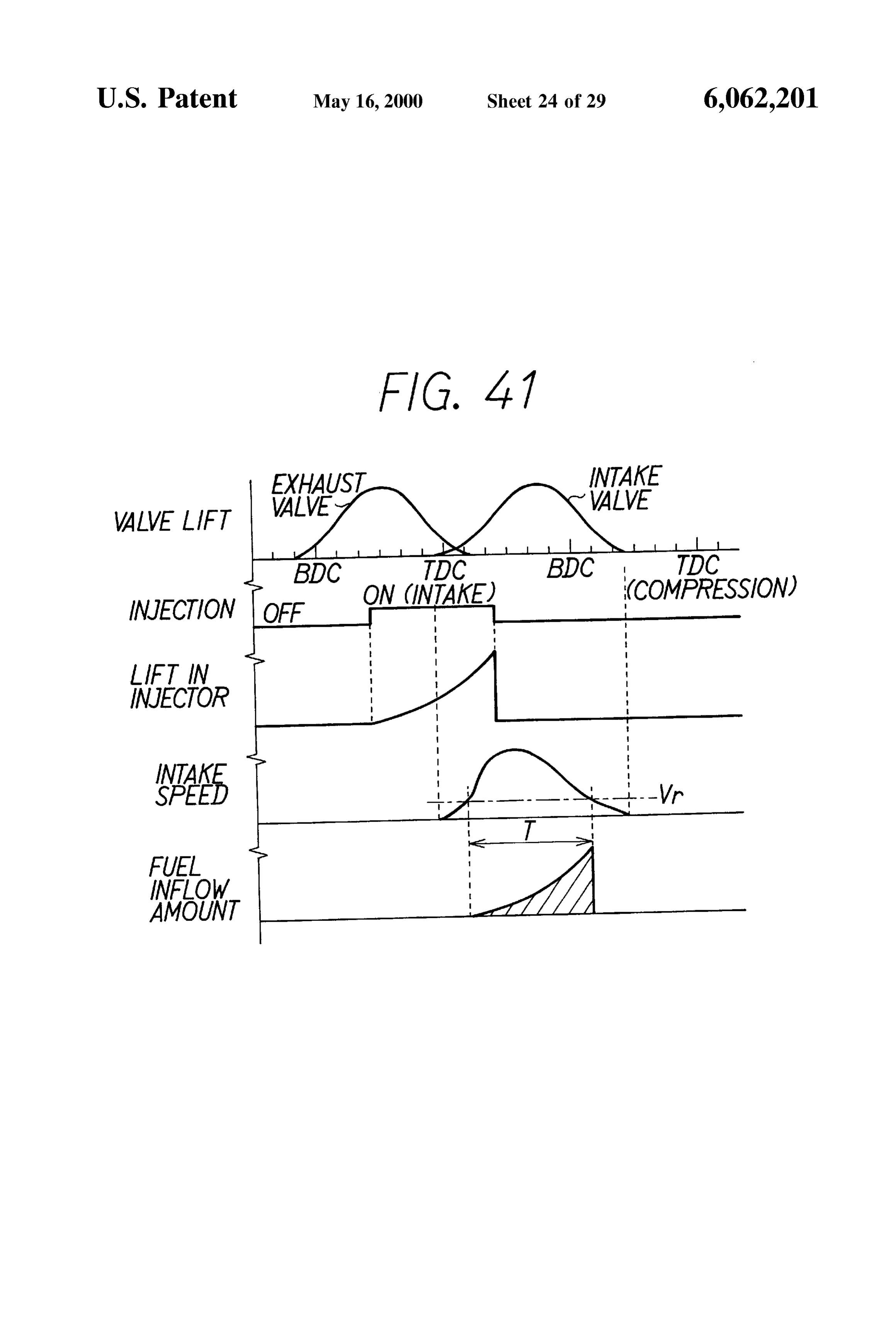
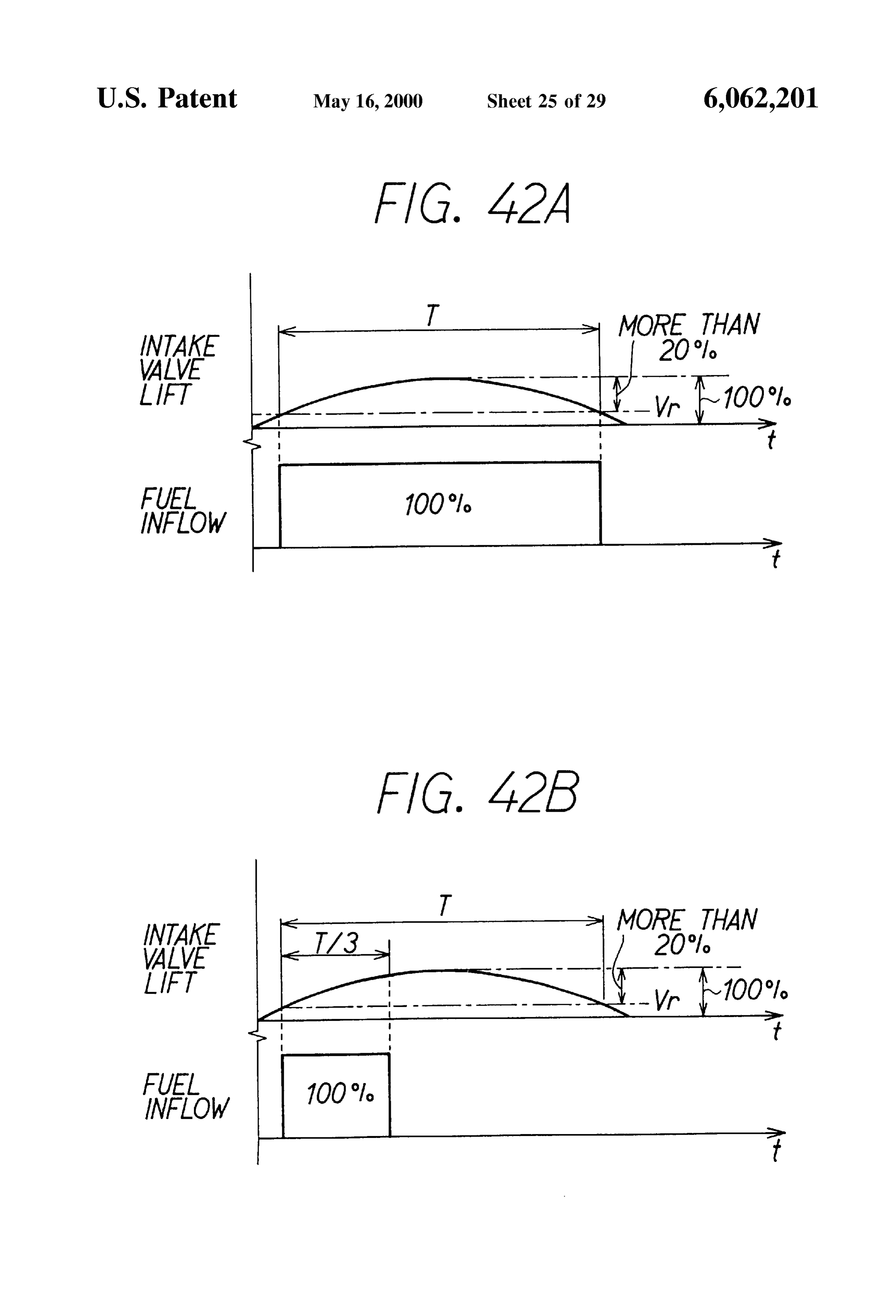
FIGS. 37A and 37B are graphs showing a difference of which outputs a wide-ranged and linear air-fuel ratio Signal effects caused by the difference of fuel particle sizes SMD; in proportion to concentration of oxygen (or concentration FIG.38 is a time chart showing an early injection accord 15 of carbon monoxide which is unburnt gas) within exhaust ing to a first modification of the Second embodiment; gas is provided within the exhaust pipe 3. Further, a water FIG. 39 is a time chart showing a supplemental injection temperature Sensor 23 for detecting temperature of coolant according to the first modification of the Second embodi water is provided on the cylinder 9 (water jacket). ment, An electromagnetically driven injector 18 is provided at FIGS. 40A and 40B are graphs showing a difference of an intake port 17 of the engine 1. Fuel (gasoline) is Supplied effects caused by the difference of fuel particle sizes SMD from a fuel tank 19 to the injector 18. A multi-point injection according to the first modification of the Second embodi (MPI) system having the injector 18 per each bifurcated pipe ment, of an intake manifold are structured and the injectors 18 of FIG. 41 is a time chart showing valve lifts of intake and 25 25each cylinder are connected to each other by a delivery pipe exhaust valves when opened, fuel injection timing of the air-assisted in the present embodiment. It is noted that the four-hole injector, a valve lift of the injector, a change of the intake ment. injector 18 is adopted in the present embodi flow Speed when the intake valve is opened and an amount of fuel Supplied into the cylinder in a process of varying a A fuel pump 26 for supplying fuel to the delivery pipe 25 fuel amount according to a third embodiment; while controlling pressure of the fuel (fuel pressure) is FIGS. 42A and 42B are graphs showing a variable fuel disposed fresh air between the fuel tank 19 and the injector 18. Then,
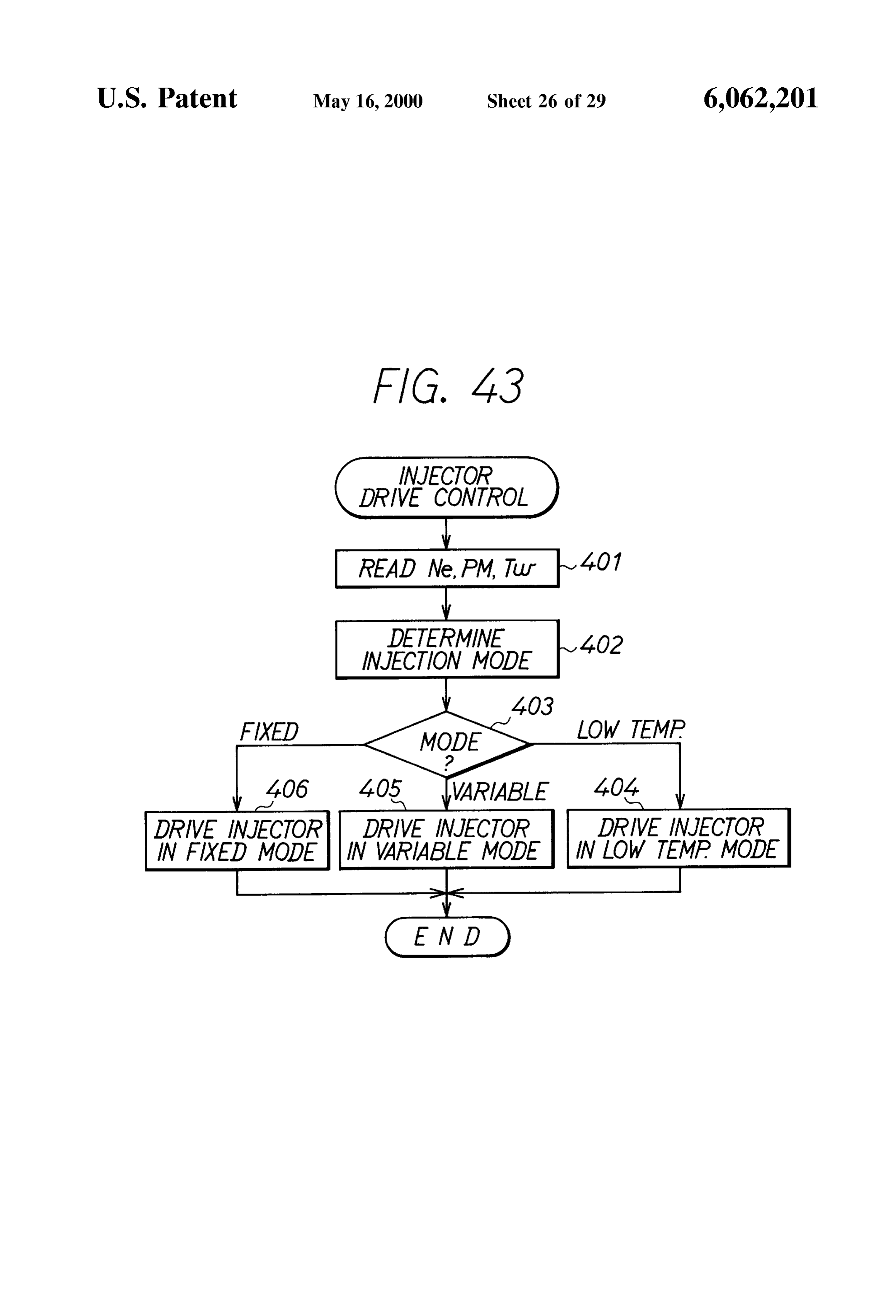
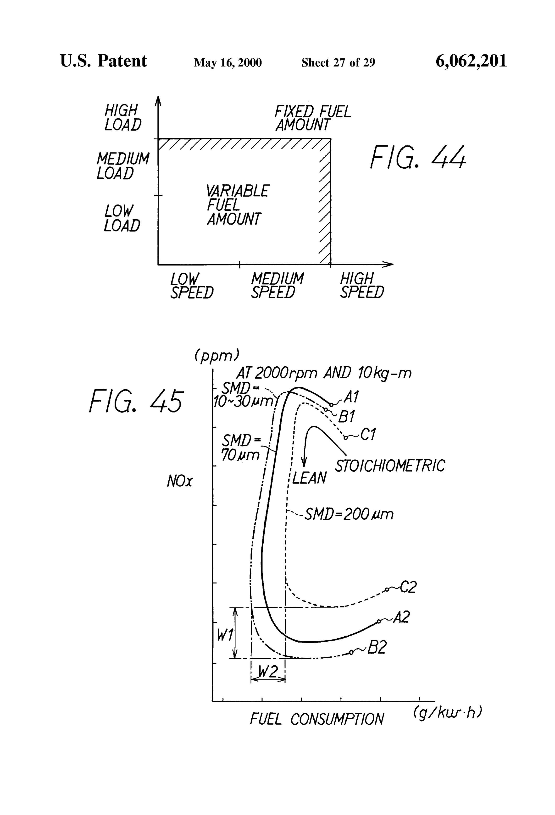
Supplied from the upstream of the intake pipe is amount mode and a fixed fuel amount mode, mixed with the fuel to be injected by the injector 18 in the FIG. 43 is a flow chart showing a routine for controlling intake port 17 and the mixture is Supplied into the combus drive of the injector according to the third embodiment; tion chamber 13 (within the cylinder 9) as the intake valve FIG. 44 is a map showing fuel injection modes corre 35 14 opens.
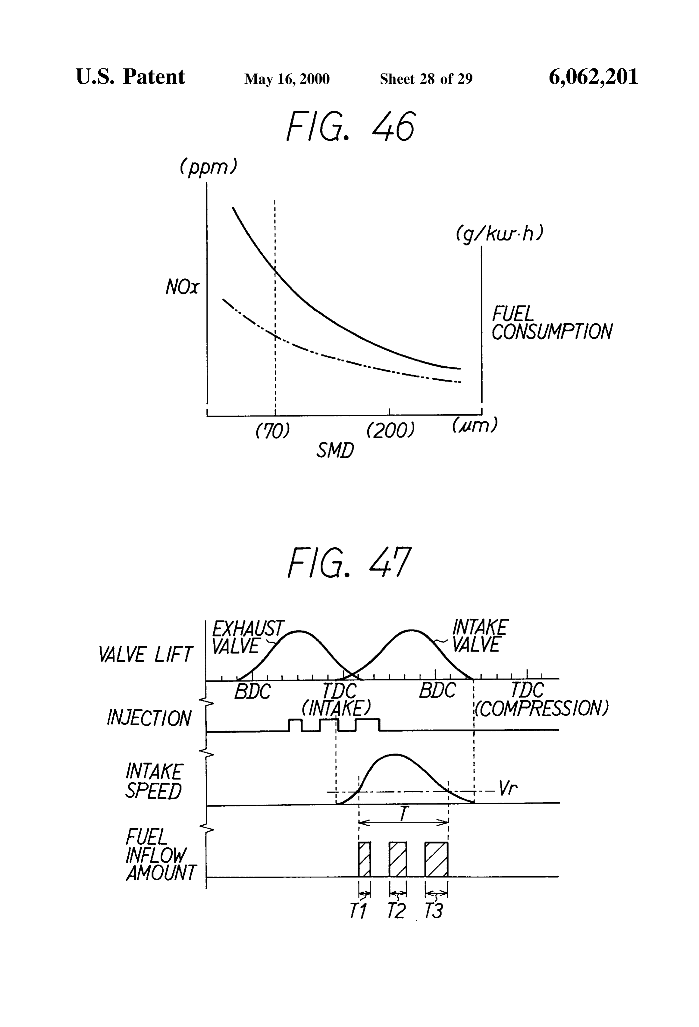
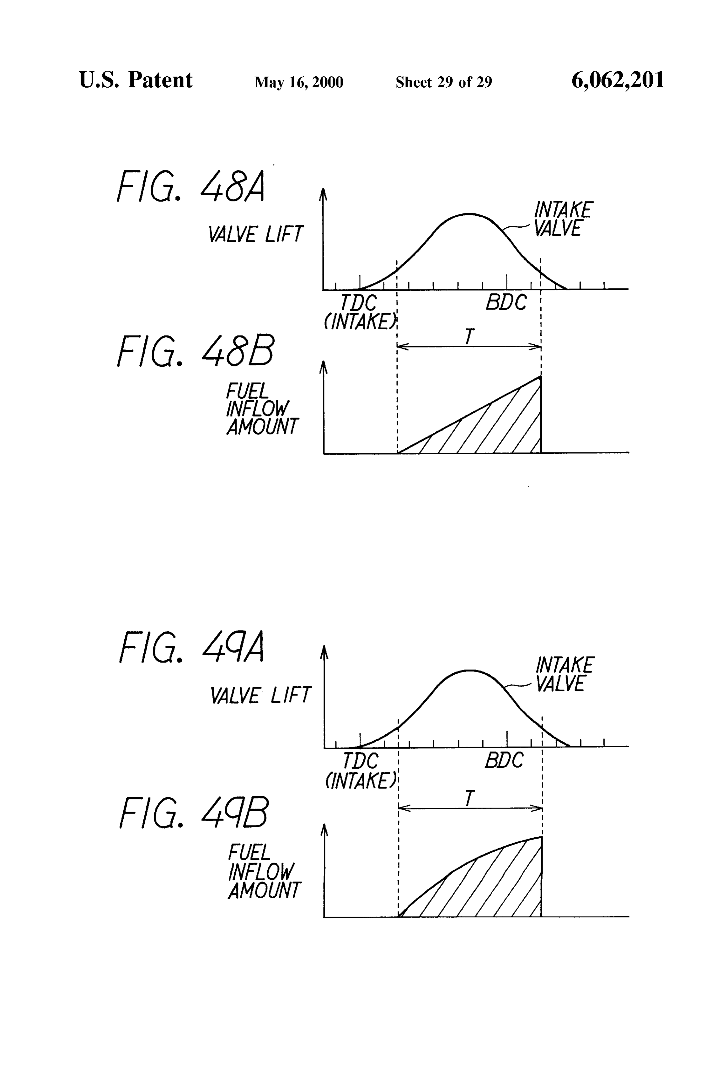
Sponding to engine operating States, An ignition plug 27 disposed at the cylinder head 12 FIG. 45 is a graph showing experimental data for con igniteS when igniting high Voltage is Supplied from an firming the effect of the third embodiment; igniter 28. A distributor 20 for distributing the igniting high FIG. 46 is a graph showing experimental data for con 40 Voltage to the ignition plug 27 of each cylinder is connected firming the effect of the third embodiment; to the igniter 28. The distributor 20 is provided with a FIG. 47 is a time chart showing valve lifts of intake and reference position Sensor 21 for outputting a pulse signal per exhaust valves when they are opened, fuel injection timing 720 CA in correspondence with states of rotation of the of the injector, a change of the intake flow speed when the crankshaft and a rotation angle Sensor 22 for Outputting a intake valve is opened and an amount of fuel Supplied into 45 pulse signal per finer crank angle, e.g., 30 CA. the cylinder according to the third embodiment; The ECU 30 is mainly composed of a microcomputer FIGS. 48A and 48B are time charts showing changes of System for example and comprises an A/D converter 31, an the amount of fuel Supplied into the cylinder according to a input/output interface (I/O) 32, a CPU 33, a ROM 34, a first modification of the third embodiment; and RAM 35, a backup RAM 36 and the like. Each detected FIGS. 49A and 49B are time charts showing changes of 50 Signal of the throttle opening angle Sensor 6, the intake the amount of fuel Supplied into the cylinder according to a preSSure Sensor 8, the A/F Sensor 16 and the water tempera Second modification of the third embodiment. ture sensor 23 is input to the A/D converter 31 to be converted from analog to digital and is input to the CPU 33
DETAILED DESCRIPTION OF PREFERRED via a bus 37. The respective pulse signals of the reference EMBODIMENTS 55 position Sensor 21 and the rotation angle Sensor 22 are input First Embodiment to the CPU 33 via the input/output interface 32 and the bus 37. The CPU 33 detects a throttle opening angle, an Suc
A System of the present embodiment controls a fuel tioned air pressure PM, an air-fuel ratio (A/F), temperature injection amount of a gasoline injection type multi-cylinder of coolant water Tw, reference crank position (G Signal) and internal combustion engine and each injector for injecting 60 an engine Speed Ne.
fuel to each cylinder is controlled by an electronic control At this time, the CPU 33 discriminates a cylinder to which unit (ECU) which is mainly composed of a microcomputer. fuel is to be injected based on the G Signal in controlling fuel The ECU controls and drives the injector disposed at an injection. The CPU 33 also controls an amount of fuel to be intake port Such that fuel is Supplied into the cylinder within injected by the injector 18 based on the various detected a predetermined period. 65 Signals indicative of operating States of the engine. Fuel is In FIG. 1, an intake pipe 2 and an exhaust pipe 3 are then injected within a predetermined period in which the connected to an engine 1. The intake pipe 2 is provided with Stroke of the engine 1 shifts from an exhaust Stroke to an
Page 34
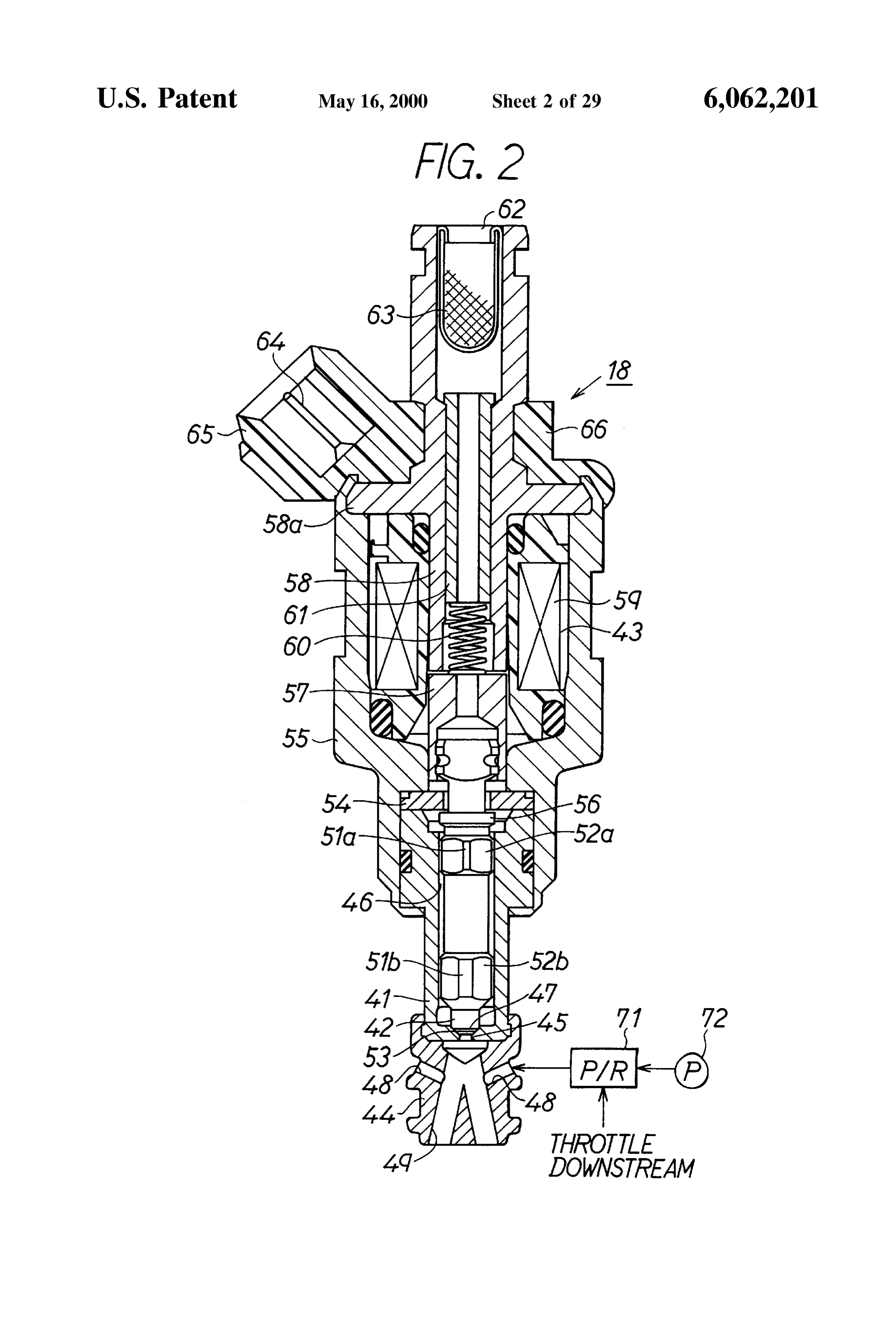
intake Stroke under the control of fuel injection achieved by position (the position shown in the figure) in which the the CPU 33 and is supplied into the cylinder (within the abutting portion 53 abuts with the valve seat 47, thus closing combustion chamber 13) as the intake valve 14 opens in the the injection port 45, and a valve opening position in which intake Stroke. the abutting portion 53 is separated from the valve seat 47 Next, the structure of the injector 18 will be explained in by a predetermined distance, thus opening the injection port detail with reference to FIG. 2. It is noted that the injector 45.
18 of the present embodiment is constructed as an electro A ring Stopper 54 is disposed at the upper end face of the magnetic valve which is a normally-closed type. valve body 41. The valve 42 is inserted through the stopper In FIG. 2, the main part of the injector 18 is divided into 54, thus protruding to the side of a casing 55. Here, the valve a valve body 41, a valve 42, an electromagnetic actuator 43 42 is provided with a flange 56 which is stretched out in the and an air-assisting adapter 44. Provided within the valve peripheral direction. When the valve 42 is pulled up when body 41 having almost a cylindrical shape are an injection the electromagnetic actuator 43 is driven, the flange 56 hits port 45 for injecting fuel into the intake pipe 2 at one end the Stopper 54, thus restricting the opening position of the thereof (lower end face in the figure) and a sliding hole 46 15 valve 42.
for slidably storing the valve 42. A valve seat 47 having a The electromagnetic actuator 43 Stored within the casing conical face is provided between the injection port 45 and 55 comprises a core (armature) 57, a stator 58 and an the sliding hole 46 of the valve body 41. electromagnetic coil 59. The core 57 is connected with the The air-assisting adapter 44 is attached on the Side of the valve 42 so that it can move in a body therewith and is urged injection port 45 of the valve body 41 (lower side in the always to the side for closing the valve 42 (lower side in figure) and guides the fuel injected from the injection port 45 FIG. 2) by a return spring 60. The stator 58 made of a into the intake pipe 2. The air-assisting adapter 44 is cylindrical magnetic Substance is disposed coaxially with provided with a plurality of air inlet ports 48 for introducing the core 57 and is fixed to the casing 55 by caulking a flange Supplementary air for accelerating atomization of fuel and portion 58a thereof by the edge of the casing 55. A pipe-like ramified passages for ramifying and injecting the mixture of 25 cylinder 61 is disposed within the stator 58. An inlet port 62 the fuel injected from the injection port 45 and the Supple for flowing in fuel is provided at the upstream portion of the mentary air introduced from the air inlet port 48 into a cylinder 61 and is provided with a filter 63. plurality of directions at predetermined angles. The ramified The electromagnetic coil 59 is connected to a terminal 64 passages 49 are ramified into two directions So that they face for taking in control signals from the outside (ECU30). This to the center of the bevel portion of the two intake valves 14 terminal 64 is supported within a connector 65 which is provided in each cylinder. It is noted that because four formed of mold resin 66 disposed at the end of the casing 55. injection ports are provided in the injector 18 of the present When fuel inflows in from the inlet port 62, it is guided embodiment, it is called a "four-port type injector'. to the sliding hole 46 via the filter 63, the cylinder 61, the A preSSure regulator 71 for controlling pressure of air core 57 and a gap between the stopper 54 and the valve 42 Supplied to the air inlet port 48 of the air-assisting adapter 44 35 in the injector 18. Then, when the electromagnetic coil 59 is is connected to the air inlet port 48 so as to control the energized by the ECU 30, it generates magnetic force and preSSure of air Supply Such that a certain difference of pulls up the core 57 in the upper direction in FIG. 2 against preSSure is provided with respect to pressure at the down the urging force of the return Spring 60. Thereby, the gap stream of the throttle valve of the intake pipe 2. An air between the valve seat 47 and the abutting portion 53 is supply pump 72 which is driven when an IG key is turned 40 opened and fuel is injected to the intake pipe 2 via the on is connected to the pressure regulator 71. Therefore, the injection port 45 as well as the ramified passages 49 of the atomization of the fuel injected from the injection port 45 is air-assisting adapter 44.
accelerated by introducing air having the predetermined Next, operations of the fuel injection control System difference of pressure with respect to the intake negative constructed as described will be explained. In the System of pressure at the downstream of the throttle valve from the air 45 the present embodiment, the operations are Summarized as: inlet port 48. The valve of the present embodiment is (a) controlling timing for flowing fuel into the cylinder at arranged such that pressurized air of around 300 kPa is Specific timing in the initial period of the intake Stroke continuously fed to the air inlet port 48 by the pressure (control of fuel inflow timing); regulator 71 and the air Supply pump 72. It may be also (b) partially injecting fuel corresponding to engine oper arranged Such that the pressurized air is Supplied by pres 50 ating States (divided or partial injection of fuel); and Surizing by the air Supply pump 72 in Synchronism with the (c) atomizing the fuel Supplied into the cylinder fuel injection timing. In Such a case, the pressurization is (atomization of injected fuel). Started just before Starting the injection and is stopped as the At first, the operation (a) of “control of fuel inflow injection finishes. timing” will be explained with reference to FIGS. 3 through The needle-like valve 42 is provided with sliding contact 55 5.
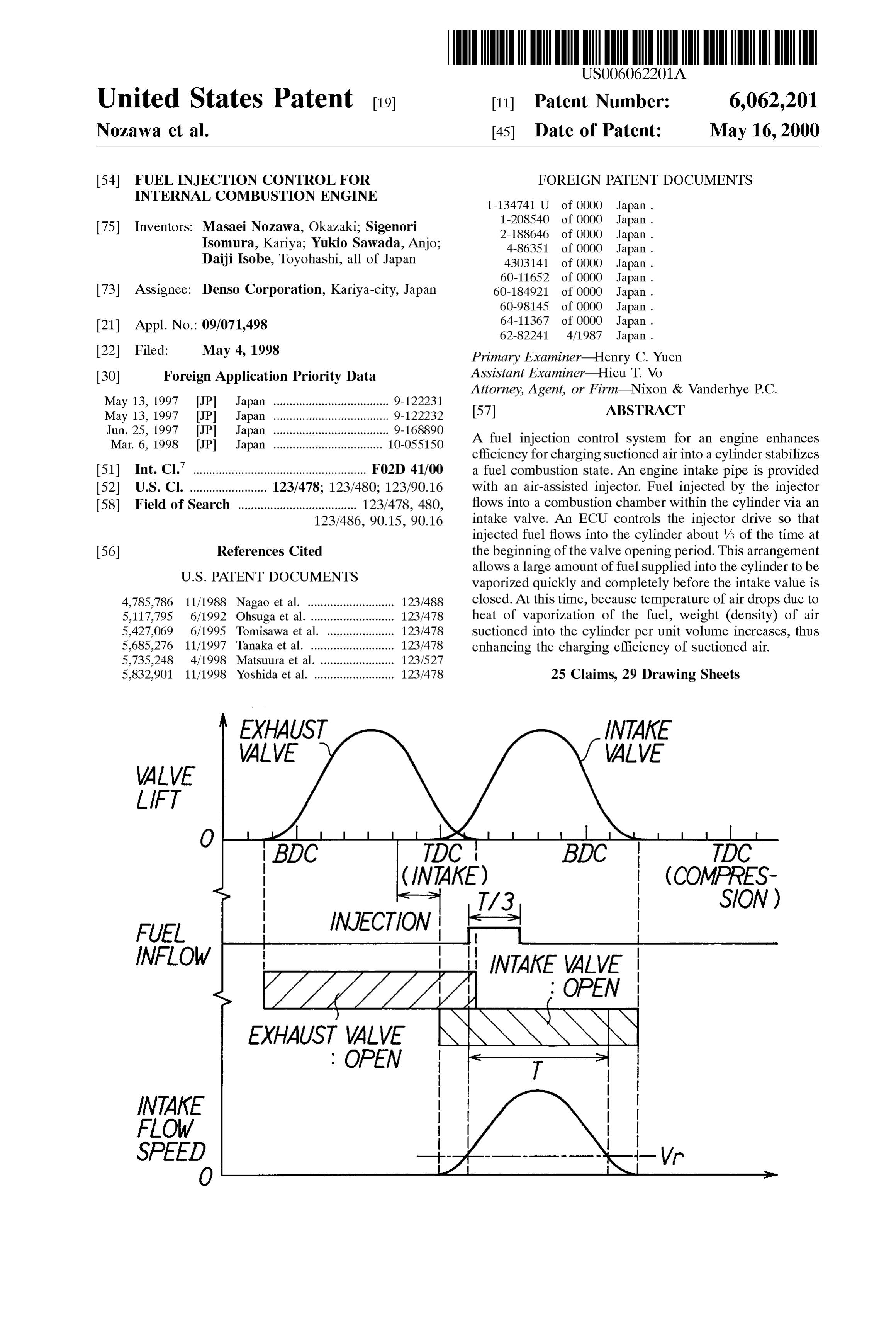
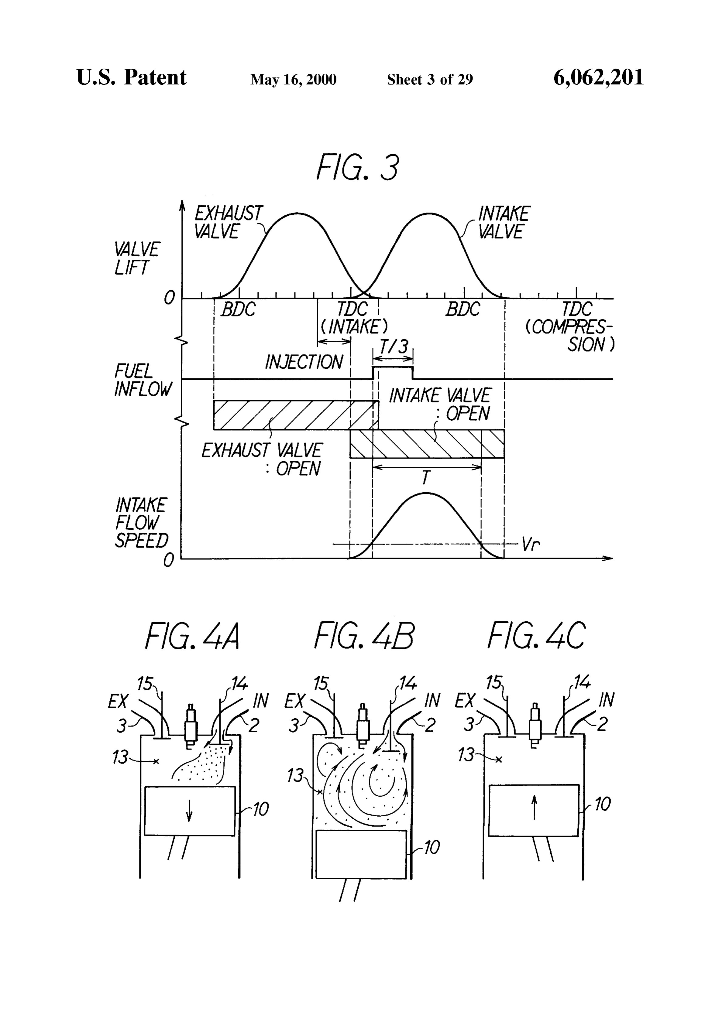
portions 51a and 51b provided at two positions in the axial FIG. 3 is a time chart showing valve lifts of the intake and direction thereof. The valve 42 slides within the sliding hole exhaust valves 14 and 15 as opened, the fuel injection timing 46 as the sliding contact portions 51a and 51b abut with the of the injector 18 and changes of intake flow speed when the inner peripheral face of the sliding hole 46. Further, the intake valve 14 is opened, wherein TDC (top dead center) valve 42 is provided with flat portions 52a and 52b provided 60 and BDC (bottom dead center) within one cycle of the piston at the regions adjacent to the Sliding contact portions 51a 10 are indicated on the horizontal axis. It is noted that and 51b in the peripheral direction. Fuel inflows through the although the intake flow Speed actually starts to increase gap provided between the flat portions 52a and 52b and the Slightly after the opening timing of the intake valve 14, those inner peripheral face of the Sliding hole 46. timings are shown in Synchronism in the figure for brevity. The valve 42 is provided also with an abutting portion 53 65 In FIG. 3, the exhaust valve 15 opens just before the BDC which abuts with the valve seat 47 of the valve body 41. The and closes right after the TDC (intake TDC). Further, the valve 42 is allowed to move between a valve closing intake valve 14 opens just before the intake TDC and closes
Page 35
right after the BDC. At this time, a period during which the the lift of the intake valve is 20% or more) and the vertical intake flow Speed exceeds a predetermined threshold value axes represent the increase of torque and the increase of HC. Vr as the intake valve 14 is opened is denoted by “T” in the It is apparent from FIG. 5 that the maximum increase of figure. This period “T” corresponds to a period during which torque can be provided when the rate of fuel inflow time is the valve lift of the intake valve 14 is about 20% or more as reduced to about 30% or less. However, there is a case when compared with the full-open time (at the time of 100%). the wetness of the cylinder increases and the unburnt HC Then, the fuel to be injected by the injector 18 is supplied turns to increase when the rate of fuel inflow time is reduced too much, i.e., the fuel inflow in the initial period of the into the cylinder within “a period of /3' at the beginning of intake Stroke is concentrated in a short time too much. the period T described in the present embodiment. At this Accordingly, time, the sprayed fuel injected by the injector 18 flows into at around 25it tois desirable to set the rate of fuel inflow time 30% in order to obtain the maximum the cylinder by being carried on the Suctioned air in the increase of torque while Suppressing the increase of unburnt initial period when the intake valve is opened. It is noted that HC. Then, fuel is supplied into the cylinder within /3 at the the fuel injection by means of the injector 18 is calculated initial period of the period T during which the intake flow reversely in correspondence with the case when the timing Speed exceeds the predetermined threshold value in the for flowing fuel into the cylinder is set at “T/3', in FIG. 3. 15 present embodiment due to Such reasons. Actually, the fuel injection timing is Set at earlier timing by Next, the operation (b) of “divided injection of fuel” will estimating a delay time until when the fuel injected to the be explained with reference to FIGS. 6 through 8. intake port 17 reaches the intake valve 14. The time indicated by “T/3” in FIG. 3 is shortened when The efficiency for charging Suctioned air is enhanced and the engine Speed increases. Similarly, the fuel injection an output torque of the engine 1 improves by flowing the amount during the time “T/3' also increases when the fuel into the cylinder within the period during which the engine load increases. In Such a case, there is a possibility valve lift is more than 20%, i.e., the period of “T/3” in the that the discharge of unburnt HC increases when all of the figure during which the intake flow speed exceeds the fuel injection amount (100%) is supplied into the cylinder at predetermined threshold value Vr. Further, the fuel Supply one time within the period “T/3”. Therefore, according to the ing method allows the torque to be increased without 25 present embodiment, a mode of injecting all of the fuel increasing unburnt HC. The torque increase will be (100%) at one time within the period “T/3” as shown in FIG. explained below with reference to FIGS. 4A through 4C. 6A (one-time injection mode) and a mode of injecting about FIG. 4Ashows a state when atomized fuel inflows into the 50% of all of the fuel within the period “T/3” and of combustion chamber 13 as the intake valve 14 is opened in injecting the remaining 50% of fuel aside from the intake the initial period of the intake stroke (the period of T/3 in stroke as shown in FIG. 6B (divided injection mode) are set. FIG.3). In this state, a large amount of atomized fuel inflows FIG. 7 is a map showing Speed ranges and load ranges of into the combustion chamber 13 together with air and is the engine 1 for Selecting either the “one-time injection Started to be vaporized in the early stage as the piston 10 mode” or “divided injection mode”. In the figure, a low-to moves down. Then, because heat is consumed when the fuel medium Speed range and a low-to-medium load range is vaporized, temperature of the ambient Suctioned air drops. 35 (Slant-lined range in the figure) corresponds to a domain FIG. 4B shows a state at or just before the bottom dead (one-time injection domain) in which fuel is injected by the center (BDC) of the piston 10. At this time, only air is injector 18 in the one-time injection mode and a high Speed Suctioned when the intake valve 14 is opened. The low range or a high load range corresponds to a domain (divided temperature air within the combustion chamber 13 is agi injection domain) in which fuel is injected by the injector 18 tated by the Suctioned air, dropping the temperature of the air 40 in the divided injection mode.
further. It is noted that at this point of time, vaporization of Further, it is necessary to change a fuel inflow amount the atomized fuel inflown during the initial period of the injected by the injector 18 per unit time in correspondence intake Stroke is almost completed. Then, as the density of the with operating States in order to realize the fuel inflow within air increases due to the drop of the air temperature, the the period T/3 as described in the whole range of the Volume of air per unit weight decreases. Accordingly, the 45 operation of the engine. That is, in case of the one-time amount of air Suctioned within the period during which the injection mode, although the injection flow amount of the intake valve 14 is opened increases. That is, efficiency for injector 18 per unit time may be leSS during when the engine charging the Suctioned air is improved and output torque of Speed or load is low, the injection flow amount of the injector the engine 1 is increased. 18 per unit time must be increased when the engine Speed or FIG. 4C shows a state within the cylinder in a compres 50 load increases. Then, according to the present embodiment, Sion Stroke. Because the fuel is fully vaporized, there the injection flow amount per unit time is controlled by remains the least atomized fuel. varying pressure of fuel (fuel pressure Pf) fed to the injector There is a possibility that non-vaporized fuel remains 18 by controlling a command current (pump current) for the even when the intake valve 14 is closed and is exhausted as fuel pump 26.
unburnt HC (wetness of fuel also increases) in the existing 55 FIG. 8 is a map for setting the fuel pressure Pf in system in which fuel is continuously flown in until the later correspondence with the engine Speed and the engine load. Stage of the intake Stroke. Further, because the heat of A slant-lined range in FIG. 8 is the same domain with the Vaporization is not used effectively when the vaporization of one-time injection domain in the map in FIG. 7. Within the fuel is insufficient, the efficiency for charging Suctioned air domain, a low fuel pressure domain, a medium fuel preSSure is low. Contrary to this, the efficiency for charging Suction 60 domain and a high fuel pressure domain are Set correspond air is improved by using the heat of vaporization effectively ing to the engine Speed and the engine load. It is noted that in the System of the present embodiment. the medium fuel pressure domain is set in the domain (high FIG. 5 is a graph showing experimental data Supporting Speed and high load domain) corresponding to the divided the phenomenon explained with reference to FIG. 4, wherein injection domain in FIG. 7.
the horizontal axis represents a rate of time during which 65 Next, the operation (c) of “atomization of injected fuel” fuel is supplied into the cylinder in the initial period of the will be explained below with reference to FIGS. 9 through intake Stroke (actual fuel inflow time/total time during which 12.
Page 36
That is, according to the present embodiment, the air into the cylinder in the initial period of the intake stroke. It assisted injector 18 is used and the fuel is atomized Such that is considered to have happened because the fuel inflows into the particle size of the fuel (SMD: Sauter's Mean Diameter) the cylinder without adhering on the intake port 17 by being falls within a predetermined range by controlling preSSur carried on the flow of the Suctioned air by ending the ized air fed to the injector 18. It is noted here that the particle injection before opening the intake valve. It can be under size SMD has a relationship as shown in FIG. 9 with respect stood from this result that the worsening of emission caused to pressure of the pressurized air of the injector 18. That is, by the difference of air-fuel ratio in transition periods may the larger the pressure of the pressurized air, the Smaller the be Suppressed considerably as compared with the prior art fuel particle size SMD becomes. The fuel is thus atomized. Systems. It is confirmed that this phenomenon is provided in FIG. 10 shows a result of the effect of the fuel particle size water is asmanner the same high as even when the temperature of coolant
SMD on the increase of torque studied and confirmed by an actual engine. In the graph, the Vertical axis represents the visualizing the sprayfrom
It is also observed experimental results provided by increase of torque when the fuel particle size SMD is favorite spray is attained andinto of fuel the intake port 17 that changed by controlling the pressure of air fed to the injector cylinder ideally when the atomizedmixture the flows into the 18 (0 to 500 kPa) under the condition of Ne=2000 rpm and timing just before opening the intake valve 14 (30at CA 15 fuel is injected the
WOT (wide-open throttle indicative of full load). It is noted before the intake TDC).
that at this time, the-operation (a) of the “control of fuel Next, various operational processes implemented by the inflow timing” is implemented to flow the fuel into the CPU 33 within the ECU 30 to control the fuel supplying cylinder within the period of T/3 at the beginning of the operation period T during which the intake flow speed exceeds the FIGS. 13 will be explained with reference to flow charts in through 15. The TAU calculating routine in FIG.
predetermined value.
As shown in FIG. 10, the smaller the fuel particle size 13 is cylinder executed in synchronism with the injection of fuel into SMD, the greater the increase of torque is (by about several each the other (per 180 CA in the present embodiment) and routines in FIGS. 14 and 15 are executed by timer %). It is also considered that there is an optimum value of the fuel particle size SMD for bringing out the effect of heat 25 interruption at a predetermined cycle. of vaporization in maximum and estimating from the result theWhen the TAU calculating routine in FIG. 13 is started, CPU 33 calculates at first a fuel basic injection time Tp of the graph and others, the optimum value of the SMD is corresponding to an engine Speed Ne and an intake preSSure found to be around 10 to 30 um.
When the fuel is supplied to each cylinder by the method PM at that time by using a basic injection map Stored in advance in the ROM 34 in Step 101. Further, the CPU 33 described in the operation (a), the fuel is liable to be carried discriminates whether a known condition of air-fuel ratio on the flow of air when the intake valve 14 opens, thus F/B holds or not in Step 102. Here, the condition of air-fuel reducing the adhesion of fuel on the intake port 17 (port wet) ratio F/B includes that the coolant water temperature Tw is and considerably reducing a spike of air-fuel ratio during transition periods of the engine. This effect of reducing the more than a predetermined temperature, the engine is not in Spike of air-fuel ratio may be enhanced further by control 35 high Speed and high load States, the A/F Sensor 16 is in the ling the fuel particle size SMD at a predetermined value. A active State and others.
result provided by confirming this effect by an actual engine When it is discriminated to be NO in Step 102, the CPU will be explained below with reference to FIG. 11. 33 advances to Step 103 to set F/B correction factor FAF to The experimental result shown in FIG. 11 is what lean open-loop “1.0'. That is, FAF=1.0 means that the air-fuel ratio is Spike or rich Spike of the air-fuel ratio is generated by 40 Step 102, the controlled. When it is discriminated to be YES in increasing/decreasing pressure in the intake pipe under the correction factor CPU 33 advances to Step 104 to set the F/B FAF.
condition of no low temperature correction from Ne=2000
The air-fuel rpm, co Tw=20° C. and the air-fuel ratio=stoichiometric control theory is implemented ratio feedback (F/B) based on the advanced ratio (14.7). in the present embodiment. In In Such experiment, the pressure in the intake pipe is 45 controlling F/B, the F/B correction factor FAF for making a changed stepwise from 400 mmHg to 600 mmHg as shown result detected by the A/F Sensor 16 to agree with a target air-fuel ratio is calculated by using the following expres in FIG. 12A during the lean spike of the air-fuel ratio. On the Sions (1) and (2). It is noted that a procedure for Setting the contrary, the pressure in the intake pipe is changed Stepwise from 600 mmHg to 400 mmHg as shown in FIG.12B during Application F/B correction factor FAF is disclosed in Japanese Patent the rich spike of the air-fuel ratio. 50
A difference AA/F of the air-fuel ratio to the lean side or FAF = Kl. + K2. FAF1 + ... + Kn+ 1. FAF + ZI (1) to the rich Side during the lean or rich Spike is plotted on the vertical axis of FIG. 11 for each whose fuel particle size ZI = ZII + Ka. (TG - ) (2) SMD is 20 tim, 50 um and 200 lum. The horizontal axis of the graph in FIG. 11 represents a crank angle of the engine 55 1. Supposing that the injection ending timings in which the In the expressions (1) and (2), a denotes a converted value time until when the fuel is supplied into the cylinder is of air-fuel ratio of the current produced by the A/F sensor 16, considered are 30 CAbefore the intake TDC, 120 CA after 2 TG denotes the target air-fuel ratio, K1 through Kn+1 the intake TDC (center of opening of intake valve) and 30 denotes F/B constants, ZI denotes an integral term and Ka CA after the compression TDC, respectively, the graph 60 denotes an integral constant, respectively. The Subscripts 1 shows respective AA/F with those crank angles. through n+1 are variables indicative of a number of times of It is apparent from FIG. 11 that the smaller the fuel control from the Start of Sampling.
particle size SMD, the Smaller the difference AA/F of the After setting the FAF value, the CPU 33 calculates the air-fuel ratio is at either cases of the lean and rich Spikes. basic injection time Tp, the F/B correction factor FAF, other Further, it is found that the difference AA/F of the air-fuel 65 correction factor FALL corresponding to various correction ratio is minimized when the injection ending timing is Set factorS Such as water temperature, load of air-conditioner before the opening of the intake valve so that fuel inflows and the like, and the final fuel injection time TAU from an
Page 37
invalid injection time Tv by using the following expression Step 303. Thereby, an injection flow amount per unit time of (3) in Step 105. the injector 18 is determined. As a result, the-one-time
injection or the divided injection can be realized regardless whether or not the engine Speed or the engine load fluctu
After calculating the fuel injection time TAU, the CPU 33 ateS.
ends this routine once. The following results may be provided by the present When the routine for controlling drive of the injector embodiment described in detail:
shown in FIG. 14 is activated by the timer interruption of the (A) The drive of the injector 18 is controlled such that fuel predetermined cycle, e.g., 4 msec., the CPU 33 reads the injected by the injector 18 flows into the cylinder engine operating States Such as the engine Speed Ne, the (within the combustion chamber 13) within the time of intake pressure PM, the coolant water temperature Tw and about/3 at the beginning of the valve opening period of the like in Step 201. Then, it determines a fuel injection the intake valve 14 in the present embodiment (FIG.3). mode based on the operating States read as described in Step According to this arrangement, the large amount of fuel 202. In determining the fuel injection mode, the CPU 33 Supplied into the cylinder is vaporized in the early Stage selects either the “one-time injection mode” or the “divided 15 and the vaporization of the fuel Supplied into the injection mode” corresponding to which Speed range of low, cylinder is completed before the intake valve 14 is medium or high the engine Speed Ne is located or to which closed and the intake is finished. At this time, weight load range of low, medium and high the engine load (intake (density) of the air Suctioned within the cylinder per pressure PM) is located by using basically the map shown in unit Volume increases because the temperature of air FIG. 7. However, fuel is injected in a “low temperature drops due to the heat of vaporization of the fuel. AS a mode” in Starting the engine 1 at low temperature for result, the efficiency for charging the Suctioned air may example without injecting fuel in the two modes in the be enhanced and the combustion State of the engine 1 present embodiment. Accordingly, one fuel injection mode may be stabilized. Further, much air may be Suctioned is Selected among the above three modes including the low and the output torque may be improved. temperature mode in determining the mode in Step 202. 25 (B) The timing for flowing the fuel injected by the injector After that, the CPU 33 discriminates the fuel injection 18 into the cylinder is limited within the period during mode determined as described in Step 203. At this time, which the intake flow Speed exceeds the predetermined when the CPU 33 discriminates it to be the “low temperature threshold value Vr when the intake valve 14 is opened. mode” in Starting the engine 1 in low temperature for This arrangement allows the problem that the injected example, it advances to Step 204 to drive the injector 18 in fuel adheres on the wall surface of the intake port to be the low temperature mode to inject fuel. The injector is avoided (port wetness decreases) because the fuel driven in the low temperature mode by injecting the fuel injected by the injector 18 is liable to be carried on the before the intake Stroke and by flowing the fuel to be flow of the suction air when the intake valve is opened injected into the cylinder across the whole range of the by flowing the fuel within the period during which the intake Stroke. It corresponds to the fuel injection operation 35 intake flow Speed is fast.
of the conventional System. (C) The decrease of the fuel port wetness also allows to When the CPU 33 discriminates it to be the “one-time injection mode”, it advances to Step 205 to drive the injector provide an effect that Spikes of air-fuel ratio decreases 18 in the one-time injection mode to inject fuel. In the considerably during the transient operation of the one-time injection mode, the fuel injection timing is Set at 40 engine 1.
the timing of /3 of the initial period of the intake Stroke as (D) AS the method for driving and controlling the injector shown in FIG. 6A (actually, at timing earlier by a flying time 18, the “one-time injection mode” and the “divided of the injected fuel). injection mode' is Selected corresponding to the rota When the CPU 33 discriminates it to be the “divided tional and load States of the engine 1 in the present injection model”, it advances to Step 206 to drive the 45 embodiment (FIGS. 6A, 6B, 7 and 14). Thereby, the injector 18 in the divided injection mode to inject fuel. In the atomization of the fuel Supplied into the cylinder is divided injection mode, the fuel injection timing is Set at the accelerated, improving the efficiency for charging air timing of /3 of the initial period of the intake Stroke and at and increasing the torque. In addition to that, unburnt the predetermined timing after the intake Stroke as shown in fuel (HC) is Suppressed from being emitted during FIG. 6B (actually, at timing earlier by the flying time of the 50 when the engine 1 is operated at high Speed or at high injected fuel). load.
The CPU 33 outputs a driving signal corresponding to (E) The pressure of fuel (Pf) supplied from the fuel tank each injection mode to an injector driving circuit not shown 19 to the injector 18 is controlled by driving the fuel in Steps 204, 205 and 206 and ends the routine in FIG. 14 pump 26 in the present embodiment. This arrangement once after processing each of those Steps. 55 allows the injection flow amount per unit time to be When the routine for controlling the fuel pressure in FIG. modified by changing the fuel preSSure Pf, allowing 15 is activated by timer interruption of a predetermined also to deal with a case when the engine Speed is cycle, e.g., 32 mSec., the CPU 33 reads the operating States increased. That is, it is possible to realize it at any of the engine Such as the engine Speed Ne and the intake engine Speed range when fuel to be injected by the pressure PM in Step 301 at first. Then, it determines the fuel 60 injector 18 is supplied into the cylinder within the pressure Pf based on the operating states in Step 302. In Specific time of the intake Stroke. determining the fuel pressure Pf, the CPU 33 selects either (F) The fuel to be injected by the injector 18 is atomized low, medium or high fuel preSSure Pf corresponding to the by controlling the pressure of air fed to the injector 18 engine speed Ne and the engine load (intake pressure PM) by using the air-assisted injector 18 and by injecting the by using the mapped data shown in FIG. 8. 65 fuel to the bevel portion of the intake valve 14 at high After that, the CPU 33 drives the fuel pump 26 by a pump temperature in the present embodiment. In Such a case, current corresponding to the fuel pressure Pf determined in the vaporization of the fuel within the cylinder is
Page 38
accelerated further by atomizing the injected fuel. attached at the edge of the nozzle section 82b. The air Accordingly, temperature of air drops due to the heat of assisting adapter 44 plays the roles of accelerating the Vaporization of the fuel when the air is Suctioned into atomization of the fuel injected from the injection port 85 the cylinder, thus Steadily improving the efficiency for and of guiding the injected fuel into the intake pipe 2. charging the Suctioned air. Then, the output torque of 5 Further, a piezo-stack 89 which expands/contracts when the engine 1 increases. This is confirmed also from the Voltage is applied is disposed within the case Section 82a. results of experiments carried out by the inventors The piezoelectric stack 89 is constructed by laminating a (FIG. 10). It is noted that it is also confirmed by the number of piezoelectric elements of PZTs (lead-titanate inventors that the optimum range of the fuel particle zirconate). The ECU 30 applies a predetermined voltage to size SMD is 10 to 30 lum. that. It is noted that it is also possible to use PLZT (lead (G) The present embodiment brings about also an effect of titanate-Zirconate-lanthanate) which is one of piezoelectric improving a knock limit by flowing in fuel in the early ceramic as the piezoelectric element. A mover 90 and a Stage in the intake Stroke and due to the drop of piston 91 are fixed and connected at the lower end face of the temperature of the Suctioned air caused by the atomi piezoelectric stack 89. The piston 91 moves pursuant to zation of the fuel. FIG. 16 is a graph showing the knock 15 strain deformation of the piezoelectric stack 89. A pressure limit corresponding to the fuel particle size SMD, control chamber 92 is provided below the piston 91 in the wherein the horizontal axis represents the fuel particle figure and is communicated with the back-pressure chamber Size SMD and the vertical axis represents igniting 87 via a communication path 93.
timing. In the figure, a knock limit characteristic curve A fuel Supplying path 94 is provided through the valve La shown by a Solid line represents the experimental body 82 and one end thereof (open end of the case section result of the system of the present embodiment in 82a) is connected to the fuel pump 26 for pumping up fuel which fuel is supplied into the cylinder in the initial within the fuel tank 19. The other end of the fuel supplying period of the intake Stroke and a knock limit charac path 94 communicates with the fuel chamber 84 of the teristic curve Lb shown by an alternate dotted line nozzle section 82b.
represents an experimental result of the prior art System 25 When the fuel is injected by the injector 18, the piezo in which fuel is supplied into the cylinder in the whole electric stack 89 deforms in the contracting direction by the range of the intake Stroke. It is then apparent from FIG. voltage signal from the ECU 30, thus permitting the piston 16 that the knock limit of the characteristic curve La is 91 to retreat (upward move in FIG. 17). Thereby, a negative shifted to the advanced side more than that of the preSSure is generated within the pressure control chamber 92 characteristic curve Lb and that the knock limit is and the valve 96 moves upward going against the elastic shifted to the advanced side by atomizing the fuel to be force of the coil spring 88. As a result, the contact of the injected. Shifting the knock limit to the advanced Side valve 86 with the edge of the nozzle section 82b is released means that a compression ratio of the engine 1 may be and fuel is injected from the injection port 85. Further, when Set high. In Such a case, thermal efficiency is increased the piezoelectric stack 89 deforms in the opposite direction theoretically as it is apparent also from the following 35 (in the extending direction) and the piston 91 moves ahead, expression (4) and as a result, the output torque the valve 86 advances and the injection port 85 is closed. increases.
The arrangement allows the lift of the valve 86 to be set mth=1-(1/e) (4) at an arbitrary value by changing the Voltage applied to the 40 piezoelectric Stack 89. That is, it allows a fuel passing area
In this expression, nth denotes the thermal efficiency (%) of to be varied and the fuel injection flow amount to be changed the engine 1, e denotes the compression ratio, and k denotes without changing the fuel pressure Pf as a result. ratio of Specific heat. Specifically, the lift is controlled by applying a DC voltage of 0 to 500 volts to the piezoelectric stack 89. FIG. 18 shows
First Modification of the First Embodiment 45 a relationship between the Voltage applied to the piezoelec
Although the injection flow amount of the injector 18 per tric stack 89 and the lift of the valve of the injector 18 and unit time is changed by variably controlling the fuel pressure FIG. 19 shows a relationship between the voltage applied to Pf in the first embodiment, the injection flow amount is the piezoelectric stack 89 and the injection flow amount per changed by holding the fuel pressure Pfat a fixed value and unit time of the injector 81.
by variably controlling a lift of the valve of the injector. FIG. 50 The control of the injection flow amount made by the 17 shows a structure of a piezo-driven injector 81. piezoelectric Stack 89 as described is executed correspond In the injector 18 shown in FIG. 17, a valve body 82 has ing to the engine Speed and the engine load (intake pressure a case section 82a and a nozzle section 82b which are PM) as shown in the map in FIG. 8 for example. connected in a body by a retaining ring 82c. A sliding hole The injection flow amount per unit time injected from the 83, a fuel chamber 84 and an injection port 85 are provided 55 injector 18 is controlled by controlling the expansion and within the nozzle section 82b. A needle-like valve 86 is contraction of the piezoelectric stack 89 in the first modifi slidably fitted through the sliding hole 83 in the axial cation. Therefore, it is possible to realize it at any engine direction thereof. A back-pressure chamber 87 which com speed range when fuel to be injected by the injector 18 is municates with the sliding hole 83 and which stores a coil Supplied into the cylinder within the Specific timing in the spring 88 is provided within the case section 82a. 60 intake Stroke, in the period of /3 of the initial Stage of the Accordingly, the valve 86 is always urged to the edge Side intake Stroke.
(lower side in the figure) of the nozzle section 82b by elastic Second Modification of the First Embodiment force of the coil spring 88. Thereby, the valve 86 normally (when not-driven) contacts with the edge of the nozzle In the Second modification, a phase-driven variable valve section 82b and closes the injection port 85 by the elastic 65 timing mechanism (VVT mechanism) is provided for the force of the coil spring 88. It is noted the air-assisting engine 1 to control the timing for injecting fuel by the adapter 44 explained before with reference to FIG. 2 is injector 18 in correspondence with a control of the VVT
Page 39
mechanism while controlling timing for opening/closing the It is noted that at this time, the timing for flowing fuel into intake and exhaust valves by the VVT mechanism. the cylinder is adjusted to the Specific timing at the initial In this modification shown in FIG. 20, an intake side period of the intake Stroke, the fuel injection timing of the camshaft 101 is drivably connected with the crankshaft via injector 18 is Set by partially injecting the fuel in correspon a timing belt not shown to open the intake valve 14 at dence with the operating States of the engine (routine in FIG. predetermined timing and the intake side VVT mechanism 14) as described and the correction in Step 502 is imple 102 is provided to the intake side camshaft 101. An exhaust mented to the fuel injection timing thus Set. side camshaft 103 is also drivably connected to the crank The operations shown in FIGS. 21 and 23 will be shaft via a timing belt not shown and an exhaust side VVT explained more concretely with reference to a time chart mechanism 104 is provided to the exhaust side camshaft shown in FIGS. 24 and 25.
103. As shown in FIGS. 24 and 25, the valve opening/closing The intake side and the exhaust side VVT mechanisms timing of the intake valve 14 is changed adequately along 102 and 104 control relative rotational phases between the the VVT control. After when the injection signal turns ON, intake side and exhaust side camshafts 101 and 103 and the the fuel injected by the injector 18 flies within the intake port crankshaft, respectively, and their operation is controlled 15 and flows into the cylinder. While the opening/closing under hydraulic control attained by a Solenoid valve. That is, timing of the intake valve 14 is shifted to the advancing Side the intake side and exhaust side camshafts 101 and 103 turn in FIG. 25, the fuel injection timing (injection signal) of the to the retarding Side or the advancing Side with respect to the injector 18 also follows that and is shifted to the advancing crankshaft corresponding to the controls of the intake side side. Thereby, the inflow of fuel into the cylinder is com and the exhaust side VVT mechanisms 102 and 104 and pleted always at the moment of time when the crankshaft has corresponding to that operation, the opening/closing timing turned by 30 CA after the opening of the intake valve 14. of the intake and exhaust valves 14 and 15 are shifted to the The timing for driving the injector is controlled in corre retarding Side or the advancing Side. spondence with the control value of the intake side VVT The intake side camshaft 101 is provided with an intake mechanism 102 in this modification. At this time, the Side cam position Sensor 105 for detecting rotational posi 25 injected fuel is Supplied into the cylinder in the initial period tion of the camshaft 101 and the camshaft 103 is provided of the intake Stroke and the intake charging efficiency is with an exhaust Side cam position Sensor 106 for detecting improved even when the opening/closing timing of the rotational position of the camshaft 103. Detected values of intake valve 14 is changed by controlling the injector 18 the cam position sensors 105 and 106 are taken into the ECU corresponding to the advancement or the retardation of the 30 at any time. Beside them, the engine intake pipe 2 is intake valve 14. As a result, the combustion state of the provided with an air flow meter 107 for detecting an amount engine 1 is Stabilized, allowing the reduction of emission of Suctioned air Qa. Its detected value is taken into the ECU and the improvement of derivability to be realized. 30 at any time. Although only the opening/closing timing of the intake FIG. 21 is a flow chart showing a routine for controlling 35 valve 14 is changed by driving the intake side VVT mecha the VVT. This routine is executed by the CPU 33 within the nism 102 in the VVT control of the case, it is possible to ECU 30 with a cycle of 64 mSec. for example. It is noted that embody it by means other than that. That is, the opening/ a case of controlling the valve timing of the intake Side will closing timing of the exhaust valve 15 may be changed by be only described here. driving the exhaust side VVT mechanism 104 for example In FIG. 21, the CPU 33 reads the operating states of the 40 as shown in FIG. 26. In the figure, the opening/closing engine Such as the engine Speed Ne, the Suctioned air timing of the exhaust valve 15 is shifted to the retarding side. amount Qa, the cam position Cp and others at first in Step Further, the opening/closing timings of the both intake and 401. It then determines a target advancement of the intake exhaust valves 14 and 15 may be changed by driving the valve 14 in Step 402. Specifically, it retrieves the target intake side and exhaust side VVT mechanisms 102 and 104 advancement "ADV' corresponding to the engine Speed Ne 45 as shown in FIG. 27. In the figure, the opening/closing and the Suctioned air amount Qa at each time by using an timing of the exhaust valve 15 is shifted to the retarding side advancement map (FIG.22) stored within the ROM 34 in and the opening/closing timing of the intake Valve 14 is advance. shifted to the advancing Side.
Then, corresponding to the target advancement "ADV, The inflow of fuel into the cylinder is completed at the the CPU 33 feedback-controls the intake side VVT mecha 50 moment when the crankshaft has turned by 30 CA after the nism 102 in Step 403. Specifically, the VVT control value is opening of the intake valve 14 in either cases of FIGS. 26 found such that a phase of the intake side camshaft 101 and 27. Thereby, the excellent effects such that the intake detected by the cam position sensor 105 agrees with the charging efficiency is improved and the combustion State is target advancement and the intake side VVT mechanism 102 Stabilized are provided. A valve opening overlapping period is driven and controlled corresponding to that control value. 55 of the intake and exhaust valves 14 and 15 is extended when FIG. 23 shows a flow chart showing a part of the routine the exhaust valve 15 is controlled to the retarding side. It for controlling drive of the injector. In FIG. 23, the CPU 33 allows the EGR effect to be provided without lowering the reads the target advancement of the intake valve 14 calcu temperature within the cylinder, thus improving the thermal lated as described in Step 501. It then corrects the injection efficiency.
ending timing of the injector 18 in accordance to the target 60 According to the Second modification of the first embodi advancement “ADV” in Step 502. Then, according to this ment applied to the fuel injection control System using the modification, the injection ending timing of the injector 18 VVT mechanism, the fuel injection timing of the injector 18 may be corrected such that the inflow of fuel into the is Set by adjusting the timing for flowing fuel into the cylinder is completed at the moment when the crankshaft cylinder to the Specific timing in the initial period of the has turned by a predetermined crank angle, e.g., 30 CA, 65 intake Stroke and by injecting the fuel partially correspond always after opening of the intake valve 14 even when the ing to the operating States of the engine, and the correction Valve opening timing thereof is changed. is implemented to the Set fuel injection timing corresponding
Page 40
to the target advancement of the intake or exhaust valve 14 engine by using the maps shown in FIGS. 7 and 8 in each or 15 (Step 502 in FIG. 23). The above structure is modified embodiment, it may be modified further as described below. So as to control the drive (fuel injection timing) of the That is, FIG. 29 may be used as a map for setting the fuel injector 18 Simply in correspondence with the advancement injection mode and FIG. 30 may be used as a map for setting or retardation of the intake valve 14. Such a case also allows the fuel pressure Pf.
the control of fuel injection always synchronized with the In FIG. 29, the “one-time injection domain” (slant-lined intake Stroke to be continued. As a result, the combustion range in the figure) is set in the low speed and high load State of the engine is Stabilized and in its turn, the reduction range and in the high Speed and low load range in addition of emission and the improvement of derivability may be to that in the low-to-medium speed and low-to-medium load realized. range. Then, the domain other that is Set as the “divided It is noted that although the drive of the injector 18 is injection domain'. In this case, the time during which fuel controlled so that the fuel injected by the injector 18 flows is Supplied into the cylinder in the one-time injection mode into the cylinder within about/3 of time of the initial period is prolonged more than the case of using the map shown in of the valve opening period of the intake valve 14 in each FIG. 7. Therefore, the charging efficiency of Suctioned air is embodiment, the arrangement may be modified further. For 15 improved under the wide operating State of the engine. instance, the drive of the injector 18 may be controlled so However, whether the map in FIG. or that in FIG. 29 should that the fuel injected by the injector 18 flows into the be adopted is determined corresponding to the Specification cylinder within a first half time of the valve opening period of the engine.
(intake stroke) of the intake valve 14. In Such a case, The slant-lined range of FIG. 30 is the same with the although the provided effect drops more or leSS because the one-time injection domain of the map in FIG. 29. In the fuel inflow timing is stretched to the medium period of the range, a high fuel preSSure domain, a medium fuel preSSure intake Stroke, the effect of improving the charging efficiency domain and a high fuel pressure domain are Set correspond of Suctioned air may be assured. In short, it will do if the ing to the engine Speed and the engine load. It is noted that arrangement is what flows the fuel injected by the injector 18 in FIG. 30, a medium fuel pressure domain (domain other into the cylinder in the initial period (at the specific timing) 25 than the Slant-lined range) is set at the domain corresponding of the intake stroke such that the vaporization of the fuel to the divided injection domain in FIG. 29. within the cylinder is completed before the intake valve 14 Further, although the timing for flowing fuel injected by is closed. the injector into the cylinder is limited within the period Atomizing the injected fuel may be embodied also as during which the intake flow Speed, when the intake valve follows beside the methods described above. That is, a is opened, exceeds the predetermined threshold value (the multi-hole type (e.g., 12-hole type) injector is used by period “T” in FIG. 3) in each embodiment, this arrangement reducing the diameter of the injection port more than that of may be modified further. For instance, not only in the period the four-hole type injector and by increasing a number of during which the intake flow speed exceeds the predeter holes to 12 or more. Because it allows the effect of atomi mined threshold value, the fuel inflow timing may be set at zation of fuel to be provided even if air pressure is relatively 35 specific time within the whole period during which the low, it allows to avoid problems that the fuel inflow speed intake valve is opened. Specifically, fuel is Supplied into the is excessively increased due to the pressurization of air and cylinder within a period of /3 (or a specific period close to the wetness of the cylinder increases. that) of the beginning of the whole period during which the Further, the present invention may be embodied without 40 intake valve is opened.
atomizing the injected fuel. Although the effect of the Still more, although the engine Speed Ne and the intake invention drops more or less, it allows the objects of the preSSure PM is used as parameters representing the operat present invention of enhancing the efficiency for charging ing State of the engine in Setting the domain of the fuel Suctioned air to the cylinder and of Stabilizing the combus injection mode and the fuel pressure domain in each tion State of the engine to be attained. 45 embodiment, a throttle opening angle and a Suctioned air Although the injection amount of the first time is “about amount may be used as parameters representing the engine 50% of the total amount and the injection amount of the load for example, beside Ne and PM.
second time is “about 50%” of the total amount in executing Second Embodiment the “divided injection mode” by the injector 18 in each embodiment, this arrangement may be also changed. For 50 A System of the present embodiment is what controls a instance, in the divided injection mode, the rate of injection fuel injection amount by an ECU in the Same manner as in of the first and Second times may be set into three Stages like the first embodiment.
“70%:30%”, “50%:50%” and “30%:70%”. Specifically, Specifically, the CPU 33 discriminates a cylinder to which when the operating State of the engine is located in the fuel is to be injected in controlling the fuel injection based divided injection domain as shown in a map in FIG. 28, the 55 on the reference position signal. The CPU 33 also controls rate of injection of the Second time is increased as the engine the amount of fuel injected by the injector 18 based on Speed or the engine load becomes high. It is of course various detection Signals indicative of the operating State of possible to Set the rate of injection more finely. Such the engine. Under the control of fuel injection of the CPU arrangement allows to avoid the problems that a time is short 33, the fuel is injected within a predetermined period in in flowing fuel into the cylinder, a required fuel amount per 60 which the engine 1 is shifted to the exhaust stroke to the unit time increases and emission of unburnt HC increases in intake Stroke and the injected fuel is Supplied into the operating the engine at high Speed or high load. Such fuel cylinder (combustion chamber 13) when the intake valve 14 injection control operation is executed by the CPU 33 and is opened in the intake Stroke.
fuel injection command means in Claims is composed of the The System of the present embodiment is arranged Such CPU 33. 65 that pressurized air of around 3 kg/cm is continuously fed Although the fuel injection mode is Set and the fuel to the air introducing port 48 by the pressure regulator 71 preSSure Pf is Set corresponding to the operating States of the and an air Supply pump 72. It is noted that the pressurized
Page 41
air may be Supplied by preSSurizing air by the air Supply exceeds the predetermined threshold value Vr, as the intake pump 72 in Synchronism with the fuel injection timing. In valve 14 is opened, is represented by “T” in the figure. Such a case, the preSSurization of air is started just before the Then, in Such a case, the fuel is Supplied into the cylinder Start of the injection and is finished when the injection is with a fixed fuel inflow Speed corresponding to the temporal finished. This effectuates the atomization of fuel. mean value of the intake flow speed within the period T. The operations of the fuel injection control system of the Similarly to the “proportioning the fuel inflow speed” present embodiment may be Summarized as: described in the operation (a), the air Suctioned from the (a) homogenizing the mixture by flowing fuel into the upstream Side of the intake pipe 2 is mixed homogeneously cylinder with a fuel inflow speed which is proportional with the fuel injected by the injector 18 in the period during to the intake flow speed (proportioning the fuel inflow which the fuel inflows into the cylinder (slant-lined section Speed); in the figure) also in this case as shown in the figure. That (b) homogenizing the mixture by flowing fuel into the is, the homogenization of the mixture may be realized within the combustion chamber 13. It is noted that this is advan cylinder at a fixed fuel inflow speed corresponding to a tageous over the case of the operation (a) described in that temporal mean value of the intake flow speed into the 15 the control of the fuel pressure Pfmay be simplified and the cylinder (averaging the fuel inflow speed); operational load of the ECU 30 may be reduced. In this case, (c) partially injecting fuel corresponding to operating the predetermined fuel inflow speed is provided by control States of the engine (divided injection of fuel); and ling the fuel pressure Pf with respect to the flow speed of air (d) atomizing fuel Supplied into the cylinder (atomization around the intake valve which is measured and known in of injected fuel). advance.
At first, the operation (a) of “proportioning the fuel inflow Next, the operation (c) of the “divided injection of fuel” speed” will be explained with reference to FIG. 31. will be explained with reference to FIGS. 33A and 33B. It FIG. 31 is a time chart showing valve lifts of the intake is desirable to flow the fuel injected by the injector 18 into and exhaust valves 14 and 15 when opened, the fuel injec the cylinder in the initial period of the intake stroke in order tion timing of the injector 18, changes in the intake flow 25 to enhance the efficiency for charging the Suctioned air into Speed when the intake valve 14 is opened and the flow speed the engine cylinder due to the following reason. That is, of the fuel supplied into the cylinder, wherein TDC (top dead when fuel is suctioned in the initial period of the intake center) and BDC (bottom dead center) within one cycle of Stroke, the vaporization of the fuel is promoted, air tem the piston 10 are indicated on the horizontal axis. It is noted perature drops due to the heat of vaporization at this time that although the intake flow speed actually starts to increase and weight (density) of the air Suctioned into the cylinder per Slightly behind the opening timing of the intake valve 14, unit volume increases. As a result, the charging efficiency of those both timings are shown in Synchronism in the figure the Suctioned air is enhanced, the fuel injection State may be for brevity. Stabilized and the engine Output torque is improved. In FIG. 31, the exhaust valve 15 opens just before the This will be explained below more specifically. As shown BDC and closes right after the TDC (intake TDC). Further, 35 in FIG. 33B, the system of the present embodiment is the intake valve 14 opens just before the intake TDC and arranged So as to flow the fuel into the cylinder within an closes after the BDC. At this time, a period during which the initial period of “T/3' of the period T during which the intake flow Speed exceeds a predetermined threshold value intake flow speed within the intake Stroke exceeds the Vr as the intake valve 14 is opened is denoted by “T” in the predetermined threshold value Vr. Further, about 50% of the figure. This period “T” corresponds to a period during which 40 total fuel is injected within the period of “T/3' and the the valve lift of the intake valve 14 is more than about 20% remaining 50% of fuel is injected aside from the intake as compared with the full-open time (at the time of 100%). Stroke when the engine 1 is operated at the high Speed or Then, according to the present embodiment, the fuel is high load State in particular in order to Suppress emission of supplied into the cylinder with the fuel inflow speed which unburnt HC. A mode of injecting all of the fuel (100%) at is proportional to the intake flow speed pursuant to the intake 45 one time within the period “T” as shown in FIG. 33A will flow speed within the period T. At this time, the air Suctioned be referred to as a “one-time injection mode” and a mode of from the upstream Side of the intake pipe 2 and the fuel injecting about 50% of all the fuel within the period of “T/3” injected by the injector 18 is mixed homogeneously in the and of injecting the remaining 50% of fuel aside from the period in which the fuel is supplied into the cylinder shown intake stroke as shown in FIG. 33B will be referred to as a in the figure (Slant-lined Section in the figure). That is, the 50 “divided injection mode” hereinbelow. homogenization of the mixture may be realized within the The operation (d) of the "atomization of the injected fuel” combustion chamber 13. is the same with that described in the first embodiment. Here, the amount of the fuel injected by the injector 18 per According to the present embodiment, a map shown in unit time must be changed in each time in order to variably FIG. 34 is used basically in determining the fuel injection control the fuel inflow speed. Then, according to the present 55 mode (Step 202 in FIG. 14) to select either the “one-time embodiment, the injection flow amount per unit time is injection mode” or the “divided injection mode” correspond controlled by varying pressure of the fuel (fuel pressure Pf) ing to which range of the low Speed range, medium speed fed to the injector 18 by controlling a command current range and high Speed range the engine Speed Ne is located (pump current) sent to the fuel pump 26. or to which range of the low load range, medium load range Next, the operation (b) of “averaging the fuel inflow 60 and high load range the engine load (intake pressure PM) is speed” will be explained with reference to FIG. 32. located.
Similarly to FIG. 31, FIG. 32 is a time chart showing FIG. 34 is a map showing the Speed range and the load valve lifts of the intake and exhaust valves 14 and 15 when range of the engine 1 to Select the “one-time injection mode' opened, the fuel injection timing of the injector 18, changes shown in FIG. 33A and the “divided injection mode” shown in the intake flow speed when the intake valve 14 is opened 65 in FIG. 33B. In the figure, the low-to-medium speed range and the flow speed of the fuel Supplied into the cylinder, and the low-to-medium load range (Slant lined range in the wherein the period during which the intake flow Speed figure) represents a domain in which the fuel is injected by
Page 42
the injector 18 in the one-time injection mode (one-time “averaging of the fuel inflow speed” by which the fuel injection domain) and the high speed range or the high load is supplied into the cylinder with the fixed fuel inflow range represents a domain in which the fuel is injected by the Speed corresponding to the temporal mean value of the injector 18 in the divided injection mode (divided injection intake flow Speed are implemented Selectively corre domain). However, fuel is injected in a “low temperature sponding to the engine Speed in the present embodi mode', not injecting fuel in the-two modes, when the ment. In Such a case, the operational load of the ECU engine 1 is started at low temperature for example in the 30 (CPU33) may be reduced by flowing in the fuel into present embodiment. Then, one fuel injection mode is the cylinder by a fixed control signal (fixed fuel Selected among the three modes including the low tempera pressure) by the process of “averaging of the fuel ture mode in determining the mode. 1O inflow Speed” when the engine Speed is relatively high. Further, according to the present embodiment, a map (C) Pressure of the fuel (fuel pressure Pf) supplied from shown in FIG. 35 is used in determining the fuel pressure Pf the fuel tank 19 to the injector 18 is controlled by (Step 302 in FIG. 15) to select the fuel pressure Pf corre driving the fuel pump 26 in the present embodiment. sponding to the engine speed Ne and the engine load (intake This arrangement allows the injection flow amount per pressure PM). 15 unit time to be changed by changing the fuel preSSure Aslant lined domain in FIG. 35 is the same domain with Pfand to cause the amount of fuel Supplied into the the one-time injection domain in the map in FIG. 34, cylinder to readily follow the intake flow speed. wherein a fuel preSSure domain for “proportioning of the (D) further, according to the present embodiment, the fuel inflow speed” of the operation (a) described and a fuel drive of the injector 18 is controlled such that the fuel preSSure domain for "averaging the fuel inflow speed” of the injected by the injector 18 flows into the cylinder operation (b) described are set in correspondence with the within about /3 of time at the beginning of the valve engine Speed. Here, the fuel pressure domain for propor opening period of the intake valve 14 under the oper tioning the flow speed is Set at relatively low speed range ating State of the engine in which the engine Speed or and the fuel pressure domain for averaging the flow Speed is load is high (FIG. 5b). This arrangement allows much Set at relatively high Speed range. It is noted that a fixed fuel 25 of the fuel Supplied into the cylinder to be vaporized preSSure domain is Set in the domain corresponding to the quickly and the vaporization of the fuel Supplied into divided injection domain in FIG.34 (the high speed and high the cylinder to be completed before the intake valve 14 load domain). is closed and the intake is finished. Because the air FIG. 36 is a time chart showing a change of the fuel temperature drops due to the heat of vaporization of the preSSure Pf in the "fuel pressure domain for proportioning fuel, weight (density) of the air Suctioned to the cylin the flow speed” and a change of the fuel pressure Pf in the der per unit volume increases. As a result, the charging "fuel pressure domain for averaging the flow Speed” within efficiency of the Suctioned air is enhanced and the the slant-lined area in the map in FIG.35 in correspondence combustion state of the fuel is stabilized. Further, it with the fuel injection timing of the injector 18. The fuel allows more air to be Suctioned and an output torque to preSSure Pf changes as shown in the figures with respect to 35 be improved as compared to the prior art Systems when the injection of fuel of the injector 18. The change of the fuel compared under the same engine operating conditions. preSSure Pf is started at timing earlier than the Starting timing (E) Further, the fuel injected by the injector 18 is atomized of the fuel injection. Specifically, the fuel pressure Pf is by controlling the preSSure of the air fed to the injector controlled So as to be proportional to the intake flow speed 18 by using the air-assisted injector 18 and by injecting and the fuel pressure Pf is controlled So as to correspond to 40 the fuel toward the bevel portion of the high tempera the temporal mean value of the intake flow speed. ture intake valve 14 in the present embodiment. In such According to the Second embodiment described in detail, a case, the vaporization of the fuel is accelerated within the following effects may be provided: the cylinder by atomizing the injected fuel. (A) The amount of fuel Supplied into the cylinder per unit Accordingly, the air temperature drops due to the heat time is controlled by following (by proportioning or by 45 of vaporization of the fuel and the charging efficiency averaging) the flow speed of the air Suctioned to the of the Suctioned air is steadily improved when the air is cylinder (the combustion chamber 13) and the drive of Suctioned into the cylinder. Then, the output torque of the injector 18 is controlled such that the fuel inflows the engine 1 is increased. It is noted that the optimum into the cylinder within the period of the intake stroke range of the particle size (SMD) of the injected fuel is during which the intake flow speed exceeds the prede 50 confirmed to be 10 to 30 um by the inventors. termined threshold value Vr in the present embodiment. FIG. 37A shows a result of experiment carried out on the In Such a case, the fuel is introduced to the cylinder by optimum (minimum) fuel consumption points A and B being carried on the relatively fast intake flow Speed corresponding to the fuel particle size SMD and on changes and the mixture composed of the fuel and the air is of the air-fuel ratio corresponding to the points A and B mixed homogeneously within the cylinder. As a result, 55 when the process of “averaging of the fuel inflow Speed” is the homogenization of the mixture Suctioned into the implemented. In the figure, the point A is the point where the cylinder may be realized and the fuel is burned stably, fuel consumption is the lowest on a characteristic curve of thus expanding the control range of the fuel consump SMD=10 um shown by a solid line and the point B is the tion and air-fuel ratio. point where the fuel consumption is the lowest on a char Further, the homogenization of the mixture allows the 60 acteristic curve of SMD=200 um shown by an alternate control of fuel injection in the air-fuel ratio lean domain, i.e., dotted line. It is apparent from the comparison of those the lean burn control, to be stably realized and NOx within points A and B that the curve of the point A can realize the the emission during the lean burn control to be reduced. low fuel consumption and that the air-fuel ratio is shifted to (B) Specifically, the process of “proportioning of the fuel the lean side. FIG. 37B is a graph showing emissions of HC inflow speed” by which the fuel is supplied into the 65 and NOx when the fuel particle size SMD is 10 um and 200 cylinder with the fuel inflow speed which is propor tim, wherein points A and B correspond to the respective tional to the intake flow speed and the process of points in FIG. 37A. It is apparent from FIG. 37B that the
Page 43
finer the fuel particle size SMD (points A), the lower the Specifically, when the newest TAU value is calculated emissions of HC and NOx can be. around the intake TDC in a time chart in FIG. 39, a First Modification of the Second Embodiment difference ATAU between that TAU value (TAUnew) and a value of TAU injected early with respect to the period of the
In a first modification of the second embodiment, the intake stroke shown in FIG. 39 (TAU value calculated injector 18 is driven to inject fuel to the intake port 17 until around the compression TDC in FIG.38: TAUold) is deter a predetermined timing before the intake valve 14 is opened mined (ATAU=TAUnew-TAUold). Then if the ATAU is a (early injection) and to inject a deficiency of fuel Supple positive value, the injector 18 is driven by ATAU. It is noted mentally corresponding to the engine operating State at each that as shown in FIG. 39, the injection fuel of ATAU is time (Supplemental injection) after the early injection. Supplied into the cylinder in a later period of /s of the period FIG.38 is a time chart showing the early injection. In the T during which the intake flow Speed exceeds the predeter mined threshold value Vr.
figure, a fuel injection amount (TAU) corresponding to the engine operating State is computed around the compression The injector 18 is driven so that two fuel injections of the TDC for example and the injector 18 is driven (turned ON) 15 early injection and the Supplemental injection are not over lapped in implementing those by controlling the fuel pres corresponding to a value of the TAU. At this time, the fuel sure Pf for example.
injection is finished at least before time Tst before the intake valve 14 is opened. Thereby, the fuel injected by the injector The present embodiment provides the following effects. 18 resides within the intake port 17 within a period in which That is, while the injector 18 is driven corresponding to the the time TS elapses. At that time, the Sprayed fuel is TAU value at the timing earlier by the time required for Vaporized and the vaporized fuel is mixed with the Suctioned vaporizing the fuel at the intake port 17 (the time Tst in FIG. air homogeneously. As a result, the homogenized mixture 38) before the intake valve 14 is opened to inject the fuel flows into the cylinder (the combustion chamber 13) when within the intake port 17 (early injection), this arrangement the intake valve 14 is opened. allows the injected fuel to be vaporized and the homoge Here, the residing time indicated by Tst in FIG. 38 is a 25 neous mixture of the vaporized fuel and the Suctioned air to time necessary for vaporizing the fuel and for realizing the be accelerated while the fuel injected by the injector 18 homogeneous mixture of the fuel and the Suctioned air. resides within the intake port 17. As a result, the homoge While it depends on the fuel particle size SMD and the like, neous mixture flows into the cylinder, thus allowing the fuel it is confirmed experimentally that the residing time Tst may to be burned stably and the control range of the fuel be set within a range of 12 to 15 msec. when the fuel particle consumption and air-fuel ratio may be expanded. Further, size SMD is around 10 to 30 um. This may be analyzed as the homogenization of the mixture allows the control of fuel follows. injection in the air-fuel ratio lean domain (lean burn control) That is, when fuel is injected within an atmosphere (in the to be stably realized and NOx within emission to be reduced cylinder) of around 200° C., a time required to completely during the lean burn control. vaporize the fuel is known to be about 2 to 2.5 mSec. 35 Further, the Supplemental injection allows the deficiency Meanwhile, because temperature of a normal intake port is of fuel during burning to be avoided and the ideal burning around 50° C., a time required to almost completely vapor with the optimum fuel amount to be realized. It is noted that ize the fuel injected to the intake port is estimated to be as because the fuel amount of the Supplemental injection is follows. When temperature of fuel particle is 20° C. and very Small, it will not hamper the homogenization of the when it is injected to a cylinder having an atmosphere of 40 mixture, 200° C., a difference of temperature is 180° C. (200-20= The system of the present embodiment also allows the 180° C.). Meanwhile, when the fuel particle having 20° C. fuel consumption to be lowered and the lean air-fuel ratio to of temperature is injected to the intake port having an be realized by atomizing the fuel particle size SMD. FIG. atmosphere of 50° C., a difference of temperature is 50 C. 40A shows a result of experiments carried out on the (50-20=30° C.). Accordingly, when those two cases are 45 optimum (minimum) fuel consumption points C and D compared, the ratio of moving times of the quantity of heat corresponding to the fuel particle size SMD and on changes turns out to be 1:6. Then, the time required to vaporize the of the air-fuel ratio corresponding to the points C and D fuel in injecting to the intake port may be found by multi when the “early injection' is implemented. In the figure, the plying the time (about 2 to 2.5 mSec.) required to vaporize point C is the point where the fuel consumption is the lowest the fuel in injecting to the cylinder by Six times. That is, it 50 on a characteristic curve of SMD=10 um shown by a solid can be understood that the time required to vaporize the fuel line and the point D is the point where the fuel consumption in injecting to the intake port is about 12 to 15 mSec. (2 to is the lowest on a characteristic curve of SMD=200 um 2.5x6=12 to 15 msec.). shown by an alternate dotted line. It is apparent when those Meanwhile, when the early injection of fuel is carried out, points C and D are compared that the curve of the point C a difference of about 360 crank angle (a difference between 55 can realize the low fuel consumption and that the air-fuel the compression TDC and the intake TDC) occurs in maxi ratio is shifted to the lean side. FIG. 40B is a graph showing mum in FIG. 38 for example until when the injected fuel emissions of HC and NOx when the fuel particle size SMD (mixture) is Suctioned into the cylinder when the intake is 10 um and 200 um, wherein points C and D correspond Valve 14 is opened. At this time, there is a possibility that an to the respective points in FIG. 40A. It is apparent from FIG. actual amount of fuel Supplied into the cylinder is not 60 40B that the finer the fuel particle size SMD (points C), the enough from the fuel amount for ideal combustion depend lower the emissions of HC and NOx can be. ing on the engine operating State which changes at every Second Modification of the Second Embodiment moment. Then, the Supplemental injection is implemented after the early injection of fuel to a predetermined cylinder Similarly to the second modification of the first in the present embodiment. That is, a difference between the 65 embodiment, the Second embodiment may be modified and previous value and the current value of TAU is determined embodied by the piezoelectric type injector shown in FIG. and the injector 18 is driven corresponding to that difference. 17. That is, the control of the injection fuel amount by the
Page 44
piezoelectric Stack 89 is implemented corresponding to the tion timing of the injector 18, a valve lift of the injector 18, engine Speed and the engine load (intake pressure PM) as changes in the intake flow Speed when the intake valve 14 shown in the map in FIG. 35. Then, the processes of is opened and an amount of the fuel Supplied into the proportioning and averaging the fuel inflow Speed are appro cylinder, wherein TDC (top dead center) and BDC (bottom priately implemented. That is, this arrangement allows the dead center) within one cycle of the piston 10 are indicated injection flow amount per unit time to be changed by on the horizontal axis. It is noted that although the intake increasing/decreasing the opened valve lift of the injector 18 flow speed actually starts to increase slightly behind the by extending/contracting the piezoelectric Stack 89 and the opening timing of the intake valve 14, those both timings are amount of fuel Supplied into the cylinder (the combustion shown in Synchronism in the figure. chamber 13) to follow the intake flow speed also in this case. In FIG. 41, the exhaust valve 15 opens just before the It is noted that beside the modifications, the present BDC and closes right after the TDC (intake TDC). Further, embodiment may be realized by modifying as follows. the intake valve 14 opens just before the intake TDC and That is, although the control of “proportioning the fuel closeS right after the BDC. At this time, a period during inflow speed” for flowing the fuel into the cylinder with the 15 which the intake flow speed exceeds a predetermined thresh fuel inflow speed which is proportional to the intake flow old value Vr as the intake valve 14 is opened is denoted by Speed and the control of “averaging the fuel inflow speed” “T” in the figure. This period “T” corresponds to a period for flowing the fuel into the cylinder with the fixed fuel during which the valve lift of the intake valve 14 is about inflow speed corresponding to the temporal mean value of 20% or more as compared to the full-open time (at the time the intake flow Speed are implemented Selectively corre of 100%). It is noted that the intake flow speed rises sharply sponding to the engine speed (FIG. 35) in the embodiments, at the beginning when the intake Valve 14 is opened and this arrangement may be modified. For instance, it is poS tends to fall gradually after reaching the peak value. sible to embody a system in which only either one of the Further, the valve lift changes as shown in the figure control of “proportioning the fuel inflow speed” or the during the period when the fuel is injected by the injector 18 control of “averaging the fuel inflow speed” is adopted. The 25 and corresponding to the waveform of this valve lift, the effect of homogenizing the mixture may be provided also in amount of fuel Supplied into the cylinder per unit time Such a case. changes. Specifically, the fuel inflow amount increases Further, although the fuel injection in the “divided injec gradually advances, in the period T and the more the intake Stroke the more the increase increases gradually. That is, tion mode” is implemented so that the fuel injected by the the later the intake injector 18 flows into the cylinder within about/3 of time at to the cylinder perstroke, the more the fuel inflow amount the beginning of the valve opening period of the intake valve timing of flowing the fuel into theincreases. unit time At this time, the 14 under the engine operating condition in which the engine across the whole period of T and cylinder the valve is engaged almost lift is controlled
Speed or load is high in the embodiment, it is possible to variably by the voltage applied to the piezoelectric Stack 89 embody the System by omitting this process.
shown in FIGS. 17 through 19.
It is also possible to set the residing time Tst (FIG.38) in 35 According to the method for Supplying fuel, the mixture implementing the early injection by the injector 18 in the Suctioned into the cylinder 9 is stratified and a rich atmo first modification variably in correspondence with an intake Sphere is provided around the ignition plug 27 positioned in temperature for example. the injecting direction of the injector 18. Thereby, even if the Means for atomizing the injected fuel may be embodied air-fuel ratio of the mixture is Set in the lean domain, the also as follows beside the methods, That is, a porous type 40 mixture may be adequately burned and the air-fuel ratio (e.g., 12 hole type) injector is used by reducing the diameter domain of the fuel injection control may be extended to the of the injection port more than those of the four-hole type lean Side.
injector and by increasing the number of holes to 12 or more. Next, the operation (b) of the “control of fuel inflow Because it allows the effect of atomization of fuel to be timing” will be explained. It is desirable to flow the fuel provided even if air preSSure is relatively low, it allows to 45 injected by the injector 18 into the cylinder in the initial avoid problems that the fuel inflow speed is excessively period of the intake Stroke in order to enhance the efficiency increased due to the preSSurization of air and the wetness of for charging the Suctioned air into the engine cylinder due to the cylinder increases. In this case, it is also possible to omit the following reason. That is, when the fuel is Suctioned in the preSSurization of air by means of the air Supply pump the initial period of the intake Stroke, the vaporization of the shown in FIG. 2. 50 fuel is hastened, air temperature drops due to the heat of Third Embodiment vaporization at this time and weight (density) of the air In the present embodiment, the piezo-driven injector 18 Suctioned into the cylinder per unit Volume increases. AS a result, the charging efficiency of the Suctioned air is shown in FIG. 17 is used. Operations of the system of the enhanced, the fuel injection State may be Stabilized and the present embodiment may be Summarized as: 55 engine output torque is improved. (a) increasing the amount of fuel Supplied into the cylin Then, as shown in FIG. 42B, the system of the present der more in the later period of the intake Stroke (process embodiment is arranged So as to flow the fuel into the of variable fuel amount); cylinder within the initial period of “T/3' of the period T. At (b) controlling timing for flowing the fuel into the cylin this time, the sprayed fuel injected by the injector 18 flows der at Specific timing in the initial period of the intake 60 into the cylinder by being carried on the flow of the Stroke (control of fuel inflow timing); and Suctioned air in the initial period of the time when the intake (c) atomizing the fuel Supplied into the cylinder Valve is opened. In Such a case, the valve lift of the injector (atomization of injected fuel). 18 is set as a fixed value and the fuel inflow amount per unit At first, the operation (a) of the “process of variable fuel time is held constant.
amount” will be explained with reference to FIG. 41. 65 The mode of varying the fuel inflow amount into the FIG. 41 is a time chart showing valve lifts of the intake cylinder per unit time as described in the operation (a) will and exhaust valves 14 and 15 when opened, the fuel injec be referred to as a “variable fuel amount mode” and the
Page 45
mode of fixing the fuel inflow amount into the cylinder per of the injector 18 is controlled such that the later the unit time as described in the operation (b) will be referred to intake Stroke, the more the amount of fuel Supplied into as a “fixed fuel amount mode” hereinafter for convenience the cylinder per unit time is increased, this arrangement in the present embodiment. When the fuel inflow timing of allows the stratified mixture to be formed within the each mode is compared, all of the fuel (100%) flows into the cylinder because the large amount of injected fuel is cylinder within the period of “T” in the variable fuel amount Suctioned just before the intake valve 14 is closed. That mode as shown in FIG. 42A and all of the fuel inflows into is, the atmosphere of air-fuel ratio enough for combus the cylinder within the period of “T/3', in the fixed fuel tion is provided around the ignition plug and the Stable amount mode as shown in FIG. 42B. combustion may be realized even if it is a lean atmo The operation (c) of the "atomization of the injected fuel” Sphere as a whole. Further, because the fuel injected by is the same with that described in the first embodiment. the injector 18 is atomized, vaporization of the fuel Various operational processes implemented by the CPU within the cylinder is accelerated, thus Suppressing 33 within the ECU 30 to control the fuel Supplying opera incomplete burning due to the cylinder wet. Thereby, tions as described in the third embodiment are similar to the Stratification of the mixture Supplied into the cyl those of the first embodiment, except of the routine for 15 inder may be favorably realized. As a result, the lean controlling the drive of the injector. limit of the mixture may be extended and the engine 1 When the routine for controlling the drive of the injector may be operated in the low fuel consumption range. is activated by the timer interruption of the predetermined (B) Because the present embodiment is arranged specifi cycle, e.g., 4 msec., as shown in FIG. 43, the CPU 33 reads cally Such that the increase of the amount of fuel the engine operating States Such as the engine Speed Ne, the Supplied into the cylinder gradually increases as time intake pressure PM, the coolant water temperature Tw and elapses from the opening of the intake valve 14 (FIG. the like in Step 401. Then, it determines a mode for injecting 41), a greater effect can be provided in Stratifying the the fuel by the injector 18 based on the operating states read mixture. At this time, the fuel may be Supplied into the as described in Step 402. In determining the fuel injection cylinder adequately even when the intake flow Speed mode, the CPU 33 selects either the “variable fuel amount 25 becomes Slow in the later period of the intake Stroke as model” or the “fixed fuel amount mode” corresponding to shown in FIG. 41.
which Speed range of low, medium or high the engine Speed (C) The flow amount of the fuel injected from the injector Ne is located or to which load range of low, medium and 18 per unit time is controlled by controlling the high the engine load (intake pressure PM) is located by using expansion/contraction of the piezoelectric Stack 89 in basically a map shown in FIG. 44. the present embodiment. This arrangement allows the FIG. 44 is the map showing the engine Speed and load injection flow amount per unit time to be readily ranges for Selecting either the “variable fuel amount mode' changed by increasing/decreasing the valve lift of the shown in FIG. 42A or the “fixed fuel amount mode” shown injector 18 by extending/contracting the piezoelectric in FIG. 42B. In the figure, the fuel is injected by the injector Stack 89.
18 in the variable fuel amount mode in the range (slant-lined 35 (D) Further, according to the present embodiment, the domain in the figure) where the engine speed and load are drive of the injector 18 is controlled such that the fuel low to medium and the fuel is injected by the injector 18 in injected by the injector 18 flows into the cylinder the fixed fuel amount mode in the range where the engine within about/3 of time T at the beginning of the valve Speed and load is high. However, the fuel is injected in a opening period of the intake valve 14 under the oper “low temperature mode” in Starting the engine 1 in low 40 ating State of the engine in which the Speed or load is temperature for example without injecting fuel in the two high (FIG. 42B). This arrangement allows much of the modes in the present embodiment. Accordingly, one fuel fuel Supplied into the cylinder to be vaporized quickly injection mode is Selected among the three modes including and the vaporization of the fuel Supplied into the the low temperature mode in determining the mode in Step cylinder to be completed before the intake valve 14 is 402. 45 closed and the intake is finished. Because the air After that, the CPU 33 discriminates the fuel injection temperature drops due to the heat of vaporization of the mode determined as described in Step 403. At this time, fuel, weight (density) of the air Suctioned to the cylin when the CPU 33 discriminates it to be the “low temperature der per unit volume increases. As a result, the charging mode” in Starting the engine 1 in low temperature for efficiency of the Suctioned air is enhanced and the example, it advances to Step 404 to drive the injector 18 in 50 combustion state of the fuel is stabilized. Further, it the low temperature mode to inject fuel. The injector is allows more air to be Suctioned and an output torque to driven in the low temperature mode by injecting the fuel be improved. That is, it becomes possible to operate the before the intake stroke and by flowing the fuel to be engine while laying StreSS on the torque under the high injected into the cylinder across the whole range of the Speed or high load State.
intake Stroke. It corresponds to the fuel injection operation 55Here, experimental data for confirming the effect of the of the conventional System (in which a fuel amount per unit arrangement of flowing the large amount of fuel into the time is fixed). cylinder in the later period of the intake Stroke as described When the CPU 33 discriminates it to be the “variable fuel will be explained with reference to FIGS. 45 and 46. FIG. 45 amount mode”, it advances to Step 405 to drive the injector shows changes of emission of NOX and fuel consumption 18 in the variable fuel amount mode to inject fuel (FIG. 60 when three injectors which inject fuel having different fuel 42A). When the CPU 33 discriminates it to be the “fixed fuel particle sizes SMD and when a target value of the air-fuel amount mode”, it advances to Step 406 to drive the injector ratio control is shifted gradually from the Stoichiometric side 18 in the fixed fuel amount mode to inject fuel (FIG. 42B). (A/F=14.7) to the lean side. In the graph, a solid line The present embodiment described in detail brings about represents the experimental data when SMD=around 70 um, the following effects. 65 an alternate chain line represents the experimental data when (A) While the particle size of the fuel injected by the SMD=10 to 30 um and a broken line represents the experi injector 18 is atomized to 70 um or less and the drive mental data when SMD=200 um. Points A1, B1 and C1 in
Page 46
the respective SMD curves indicate the amount of NOx and to operate the internal combustion engine in the low fuel the fuel consumption when the Stoichiometric value is Set as consumption range also according to this modification. the target air-fuel ratio and points A2, B2 and C2 indicate the The modification may be embodied as follows: by con amount of NOx and the fuel consumption when a lean trolling the fuel inflow of one time by equalizing each of the air-fuel ratio (e.g., A/F=23) is set as the target air-fuel ratio. fuel inflow times T1, T2 and T3 and by gradually increasing However, the data of SMD=200 um is provided by the valve lift of the injector 18; by variably controlling applying the prior art fuel injection method of providing pressure of fuel (fuel pressure) Supplied to the injector 18 mixture by fuel residing within the intake port by injecting while equalizing each of the fuel inflow times T1, T2 and T3. the fuel homogeneously regardless of the period of the In this case, the later the intake Stroke, the more the fuel intake Stroke and of flowing the mixture into the cylinder inflow of one time increases by gradually increasing the fuel because it is difficult to stratify the mixture favorably, the preSSure by using the fuel pump for example, or the fuel combustion is unstabilized and it is very difficult to make the inflow may be divided into two or four or more or an injector air-fuel ratio control in the lean domain when the Stratifi other than the piezo-driven injector may be used. In short, an cation of the mixture is to be embodied like the present arrangement which allows the drive of the injector to be embodiment when SMD=150 to 200 um because the fuel 15 controlled Such that the later the intake Stroke, the more the particle size is large. fuel inflow of one time thus divided increases. At this time, when each value where the amount of NOX It is noted that beside the modification, the present and the fuel consumption turn out to be the best is compared embodiment may be realized by modifying as follows. with respect to the control of SMD=10 to 30 um and the Although the fuel particle size SMD is atomized into 10 control of SMD=200 um, it can be seen that the amount of to 30 um in the embodiment, the range of SMD may be NOX is reduced by “W1” in the figure and the fuel con changed and Set as necessary as long as it is about 70 um or Sumption is improved by “W2” in the figure in the former less. Similarly to each embodiment, the stratification of the control.
FIG. 46 is a graph showing the degree of the effect mixture and the
Supplied into the cylinder may be favorably realized combustion State may be Stabilized even in the corresponding to the fuel particle size SMD by parameter 25 air-fuel ratio lean domain also in this case. izing the effect by the emission of NOx and the fuel Further, although the fuel injection in the “fixed fuel consumption. It can be seen from FIG. 46 that the smaller amount mode” is implemented So that the fuel injected by the fuel particle size SMD, the less the amount of NOx is and the injector 18 flows into the cylinder more the fuel consumption is improved. It is noted here that at the beginning of the valve openingwithin about/3 of time the threshold value of “SMD=70 um” is set based on the Valve 14 under the engine operating condition of period the intake permissible level of the amount of NOx and the fuel con engine speed or load is high in the embodimentin(FIG. which the
Sumption and the Stable combustion State can be maintained even if the fuel injection is controlled So as to flow the large itThat is possible to embody the System by omitting this process.
is, the control of the variable fuel amount mode shown amount of fuel into the cylinder in the later period of the in FIG. 42A may be implemented in the whole operation intake stroke as described when SMDs 70 um. 35 range of the engine.
First Modification of the Third Embodiment Further, the third embodiment may be embodied by Next, a first modification of the third embodiment will be modifying as described below and as shown in FIGS. 48A, explained with reference to FIG. 47. While the drive of the 48B, 49A and 49B. That is, a modes of changes of the fuel injector 18 is controlled such that the later the intake stroke, 40 inflow per unit time may be changed. In FIGS. 48A and 48B, the more the amount of fuel Supplied into the cylinder per the increase of the fuel inflow (inclination per unit time) is unit time is increased in the third embodiment, the drive of fixed and in FIGS. 49A and 49B, the increase of the fuel the injector 18 is controlled such that the fuel inflow per unit inflow is gradually reduced. In addition to that, the fuel time is equalized and the fuel inflow within the intake stroke inflow into the cylinder per unit time may be increased is divided into a plurality of times and such that the later the 45 Stepwise.
intake stroke, the more the fuel inflow per one time divided Atomizing the injected fuel may be embodied also as as described increases in this modification. At this time, the follows beside the methods, That is, a multi-hole type (e.g., duration of the valve lift is controlled while fixing (constant) 12-hole type) injector is used by reducing the diameter of the the valve lift of the injector 18. It is noted that the atomi injection port more than those of the four-hole type injector Zation of fuel is implemented in the Same manner with the 50 and by increasing a number of holes to 12 or more. Because third embodiment, it allows the effect of atomization of fuel to be provided even Specifically, the fuel is injected by the injector 18 by if air pressure is relatively low, it allows to avoid problems dividing into three times for example as shown in the time that the fuel inflow Speed is excessively increased due to the chart in FIG. 47 and the fuel divided into three parts is preSSurization of air and the wetness of the cylinder Suctioned into the cylinder respectively within the period of 55 increases. In this case, it is also possible to omit the “T” in the intake stroke. At this time, a time T1 during which preSSurization of air by means of the air Supply pump 72. the fuel is flown in at the first time, a time T2 during which Further, it is also possible to inject about 50% of the total the fuel is flown in at the second time and a time T3 during fuel within the period of “T” and to inject the remaining 50% which the fuel is flown in at the third time have a relationship of fuel aside from the intake Stroke aiming at Suppressing the of T1-T2<T3, i.e., the later the intake stroke, the more the 60 emission of unburnt HC when the engine 1 is operated at fuel inflow of one time increases. Accordingly, the large high Speed or high load. This process may be implemented amount of injected fuel is Suctioned into the cylinder just in place of the process of flowing all the fuel into the before the intake valve 14 is closed and the stratified mixture cylinder within the period of “T/3' as shown in FIG. 42A or may be provided within the cylinder. may be adopted together with the process shown in FIG. Similarly to the third embodiment, the stratification of the 65 42B.
mixture Supplied into the cylinder may be favorably realized While the preferred embodiments and various modifica and the lean limit of the mixture may be extended, allowing tions thereof are described, variations thereto will occur to
Page 47
those skilled in the art within the scope of the present an injector for injecting fuel to be Supplied into the inventive concepts which are delineated by the following cylinder during the period of an intake Stroke of the claims. engine in which the intake valve is opened; and What is claimed is: injection drive control means for controlling drive of the 1. A fuel injection control System for an internal combus injector such that the fuel injected by the injector flows tion engine having a cylinder and an intake valve, the System into the cylinder within a predetermined portion of Said comprising: period when the intake valve is opened; and an injector for injecting fuel to be Supplied into the engine operating State detecting means for detecting oper cylinder during a period of an intake Stroke of the ating States of the engine at least including an engine engine in which the intake valve is opened; and 1O Speed and an engine load, injector drive control means for variably controlling drive wherein the injector drive control means includes: of the injector from a time at the beginning of the intake first control means for flowing the fuel injected by the stroke such that all the fuel injected by the injector injector into the cylinder at one time within about/3 flows into the cylinder within a predetermined initial limited portion of the intake stroke period in which the 15 of time from the beginning of the opening of the intake valve opens. Valve in the period from the opening to closing of the 2. A fuel injection control System as in claim 1, intake valve;
engine operating State detecting means for detecting oper Second control means for flowing the fuel injected by ating States of the engine including at least an engine the injector into the cylinder partially at two times Speed and an engine load, within about /3 of them from the beginning of the wherein the injector drive control means includes: opening of the valve in the period from the opening first control means for flowing all the fuel injected by to closing of the intake valve and within the closed the injector into the cylinder within about /3 of time period of the intake Valve; and from the beginning of the opening of the valve in the fuel injection command means for using the first and period from the opening to closing of the intake Second means corresponding to the load and Speed of Valve when the engine is detected to be not in the 25 the engine detected by the engine operating State high load or high Speed State by the engine operating detecting means and for determining rates of fuel State detecting means, and injected at two times by the Second control means. second control means for flowing about a half of fuel 6. A fuel injection control System as in claim 5, wherein: injected by the injector into the cylinder within about the fuel injection command means increases the rate of /3 of time from the beginning of the opening of the injection at the Second time more by the control means Valve in the period from the opening to closing of the when the engine Speed or the engine load is high. intake valve and flowing the remaining fuel into the 7. The fuel injection control System according to claim 1, cylinder within the closed period of the intake valve. further comprising:
3. A fuel injection control System for an internal combus a variable valve timing mechanism for controlling the tion engine having a cylinder and an intake valve, the System 35 opening/closing timing of the intake valve to an comprising: advancing Side or a retarding Side, and an injector for injecting fuel to be Supplied into the Valve timing control means for controlling the opening/ cylinder during the period of an intake Stroke of the closing timing of the intake valve by means of the engine in which the intake valve is opened; and 40 Variable valve timing mechanism, injection drive control means for controlling drive of the wherein the injector drive control means controls the injector such that the fuel injected by the injector flows timing for driving the injector corresponding to a into the cylinder within a predetermined portion of Said control of the valve timing control means. period when the intake valve is opened; and 8. The fuel injection control System according to claim 1, wherein the injector drive control means controls the 45 further comprising:
drive of the injector such that the fuel injected by the injected fuel atomizing means for atomizing the fuel injector flows into the cylinder within about /3 of time injected by the injector.
at the beginning of the valve opening period of the 9. A fuel injection control system for an internal combus intake valve. tion engine having a cylinder and an intake valve, the System 4. A fuel injection control System for an internal combus 50 comprising:
tion engine having a cylinder and an intake valve, the System an injector for injecting fuel to be Supplied into the comprising: cylinder during the period of an intake Stroke of the an injector for injecting fuel to be Supplied into the engine in which the intake valve is opened; and cylinder during the period of an intake Stroke of the injection drive control means for controlling drive of the engine in which the intake valve is opened; and 55 injector such that the fuel injected by the injector flows injection drive control means for controlling drive of the into the cylinder within a predetermined portion of Said injector such that the fuel injected by the injector flows period when the intake valve is opened; and into the cylinder within a predetermined portion of Said wherein the injector drive control means controls the period when the intake valve is opened; and drive of the injector so that the fuel is supplied into the wherein, the injector drive control means limits the timing 60 cylinder in a period of the intake Stroke during which for flowing the fuel injected by the injector into the a flow Speed of air Suctioned into the cylinder exceeds cylinder within a period during which an intake flow a predetermined value and controls an amount of fuel Speed exceeds a predetermined threshold value when Supplied into the cylinder per unit time pursuant to the the intake valve is opened. flow speed of the air Suctioned into the cylinder. 5. A fuel injection control System for an internal combus 65 10. A fuel injection control System for an internal com tion engine having a cylinder and an intake valve, the System bustion engine having a cylinder and an intake Valve, the comprising: System comprising:
Page 48
an injector for injecting fuel to be Supplied into the the injector drive control means controls the drive of the cylinder during the period of an intake Stroke of the injector such that an inflow of fuel into the cylinder is engine in which the intake valve is opened; and completed after a predetermined time after opening the injection drive control means for controlling drive of the intake valve based on the valve opening timing of the injector such that the fuel injected by the injector flows intake valve.
into the cylinder within a predetermined portion of Said bustion 15. A fuel injection control System for an internal com period when the intake valve is opened; and engine having a cylinder and an intake Valve, the System comprising:
fuel inflow amount control means for flowing the fuel into the cylinder with a fuel inflow speed proportional to an 1O an cylinder injector for injecting fuel to be Supplied into the during a period of an intake Stroke of the intake flow Speed. engine in which the intake valve is opened; 11. A fuel injection control System for an internal com fuel injection amount calculating means for calculating a bustion engine having a cylinder and an intake Valve, the fuel injection amount based on engine operating States System comprising:
an injector for injecting fuel to be Supplied into the 15 early of each moment; and cylinder during the period of an intake Stroke of the injection means for injecting fuel into an intake port engine in which the intake valve is opened; and until a predetermined time before the intake valve is opened by driving the injector corresponding to the injection drive control means for controlling drive of the calculated injection amount. injector such that the fuel injected by the injector flows 16. The fuel injection control System according to claim into the cylinder within a predetermined portion of Said 15, wherein:
period when the intake valve is opened; and the early injection means causes the injector to inject fuel fuel inflow amount control means for flowing the fuel into at timing earlier by a time required to vaporize the fuel the cylinder with a fixed fuel inflow speed correspond in the intake port before the intake valve is opened. ing to a temporal mean value of an intake flow speed. 17. The fuel injection control System according to claim 12. A fuel injection control System for an internal com 25 15, wherein:
bustion engine having a cylinder and an intake Valve, the the injector is driven Such that after injecting the fuel into System comprising: the cylinder by the early injection means, a difference an injector for injecting fuel to be Supplied into the of the fuel injection amount between the previous value cylinder during the period of an intake Stroke of the calculated by the fuel injection amount calculating engine in which the intake valve is opened; and means and the current value is Supplied into the cyl injection drive control means for controlling drive of the inder within the intake stroke of the cylinder. injector such that the fuel injected by the injector flows 18. The fuel injection control System according to claim into the cylinder within a predetermined portion of Said 15, further comprising:
period when the intake valve is opened; and fuel atomizing means for atomizing the fuel injected by first control means for flowing the fuel into the cylinder 35 the injector.
with the fuel inflow speed which is proportional to the 19. A fuel injection control system for an internal com intake flow Speed; and bustion engine having a cylinder and an intake Valve, the Second control means for flowing the fuel into the cylin System comprising:
der with the fixed fuel inflow speed corresponding to 40 an injector for injecting fuel to be Supplied into the the temporal mean value of the intake flow speed, cylinder during a period of an intake Stroke of the wherein inflow of the fuel by means of the first control engine in which the intake valve is opened; means and inflow of the fuel by means of the second fuel atomizing means for atomizing particle Size of the control means is implemented Selectively correspond fuel injected by the injector to about 70 um or less; and ing to an engine Speed. 45 injector drive control means for controlling the drive of 13. A fuel injection control System for an internal com the injector Such that the later the intake Stroke, the bustion engine having a cylinder and an intake Valve, the more an amount of fuel Supplied into the cylinder per System comprising: unit time is increased.
an injector for injecting fuel to be Supplied into the 20. The fuel injection control System according to claim cylinder during a period of an intake Stroke of the 50 19, wherein:
engine in which the intake valve is opened; the injector drive control means increases an increase of a variable valve timing mechanism for controlling timing the amount of fuel Supplied into the cylinder gradually of opening/closing the intake valve to an advancing as time passes since when the intake valve is opened. Side or retarding Side; 21. The fuel injection control System according to claim Valve timing control means for controlling the timing of 55 19, wherein:
opening/closing the intake valve by the variable valve the injector drive control means divides the inflow of fuel timing mechanism corresponding to engine operating within the intake stroke into a plurality of times to drive States, and the injector Such that the later the intake Stroke, the injector drive control means for variably controlling tim more an inflow of fuel of one time divided is increased. ing for driving the injector corresponding to control of 60 22. A method for timing the injection into a cylinder of a the valve timing control means Such that fuel infected calculated variable quantity of fuel for an engine operating by the injector flows into the cylinder only within an condition during an intake valve Stroke of an internal initial portion of the intake Stroke and only air flows combustion piston/cylinder engine, Said method comprising: into the cylinder after Said initial portion of the intake Starting fuel injection at least by the beginning of an Stroke. 65 intake Stroke, 14. The fuel injection control System according to claim Stopping fuel injection after an initial limited portion of 13, wherein: the intake Stroke; and
Page 49
Variably controlling the pressure of the fuel being injected 24. A method as in claim 22 wherein fuel injection is between Said Starting and Stopping StepS. So as to cause Started and Stopped plural times during Said initial limited Said calculated variable quantity of fuel all to be portion of the intake Stroke.
injected into corresponding cylinders during this lim 25. A method as in claim 24 wherein said initial limited ited initial portion of the intake Stroke. 5 portion is not substantially more than about /3 of the intake 23. A method as in claim 22 wherein said initial limited Stroke.
portion is not Substantially more than about /3 of the intake
Stroke.
Provenance
- Collection
- Cited prior art
- Original PDF
- patentimages.storage.googleapis.com →
- Filed
- 1998-05-04
- Pages
- 49
- Method
- pdftotext (the PDF's own text layer) + pdftoppm 300dpi page scans
- Source
- Google Patents bibliographic record
- Granted
- 2000-05-16
- Inventors
- Masaei Nozawa; Sigenori Isomura; Yukio Sawada; Daiji Isobe; Denso Corp
- Transcribed from
- patentimages.storage.googleapis.com →