patent · US4103653
Method of and apparatus for controlling ignition timing of an internal combustion engine
1 August 1978
Page 1 — bibliographic record
United States Patent (19) 11 4,103,653 Ueno et al. 45) Aug. 1, 1978
54) METHOD OF AND APPARATUS FOR (56) References Cited CONTROLLING IGNITION TIMING OF AN U.S. PATENT DOCUMENTS
INTERNAL COMBUSTION ENGINE
1,262,034 4/1918 Frazer ............................ 123/DIG. 2 2,444,199 6/1948 Klaburner ............................ 123/121 (75) Inventors: Zene Ueno, Fuchu; Akira Morita, 3,162,184 12/1964 Walker ... 123/17 A Tokyo; Atushi Chida, Sayama, all of 3,799,124 3/1974 Swain. ... 123/1 A Japan 3,906,913 9/1975 Rupe ........ ... 123/12 3,939,806 2/1976 Bradley ... 123/1 AX 4,013,050 3/1977 Lace ................................. 123/127 X 73 Assignee: Nissan Motor Company, Limited,
Japan Primary Examiner-Charles J. Myhre
Assistant Examiner-Tony M. Argenbright
Attorney, Agent, or Firm-Robert E. Burns; Emmanuel 21 Appi. No.: 635,867 J. Lobato; Bruce L. Adams 22 Filed: Nov. 28, 1975 57 ABSTRACT The ignition timing of an engine is controlled to an (51) Int. Cl’................................................ F02P 5/04 optimum value in accordance with the amount of hy 52 U.S. Cl. ................................ 123/117 R; 123/121; drogen supplied as an auxiliary fuel to the engine in 123/127 addition to a main fuel.
(58 Field of Search .............. 123/1 A, 1 R, DIG. 12, 7 Claims, 3 Drawing Figures
INTAKE MANFOLD
VACUUM
IENGINE
Page 2
Drawing sheet — no readable text.
Page 3
Drawing sheet — no readable text.
Page 4
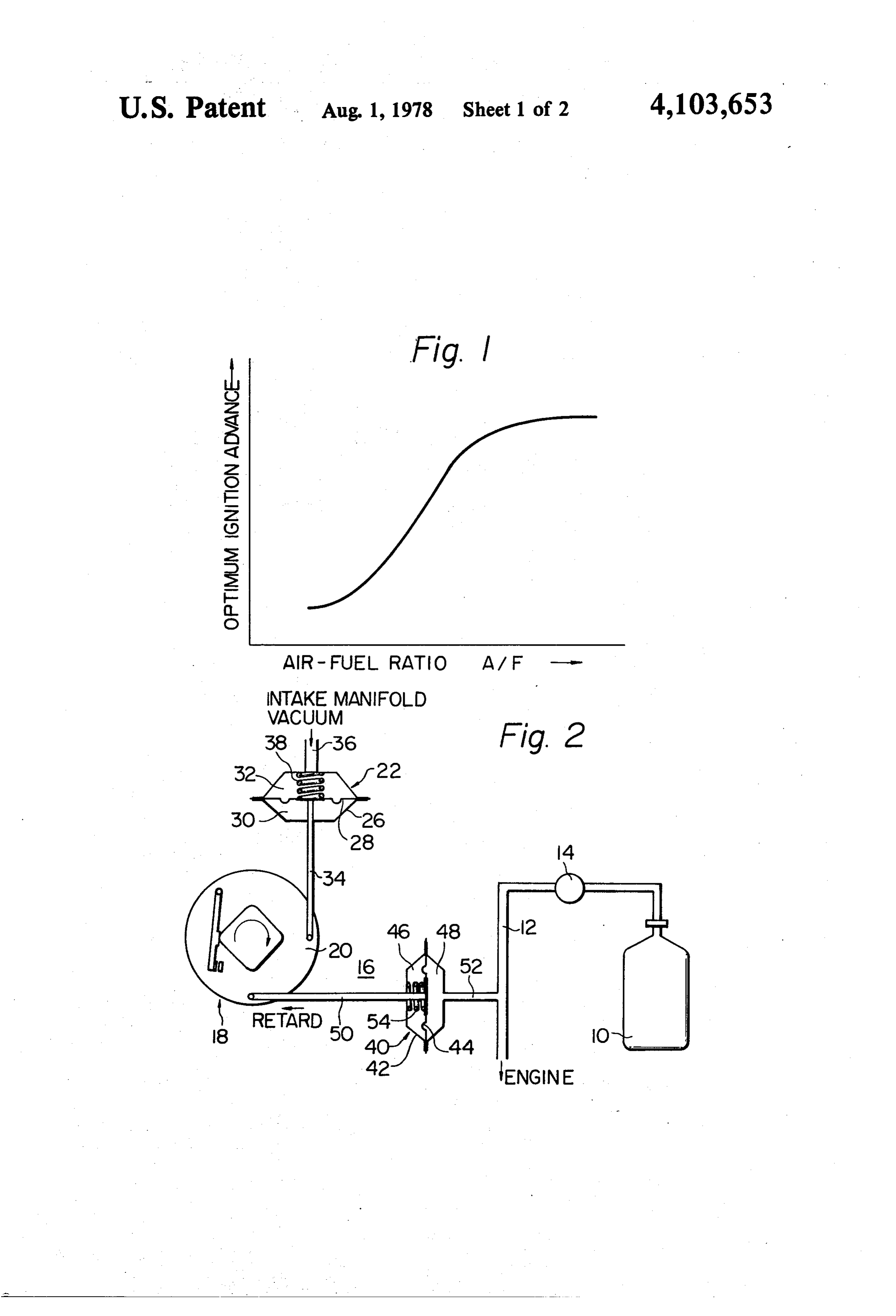
internal combustion engine and the optimum ignition
METHOD OF AND APPARATUS FOR advance;
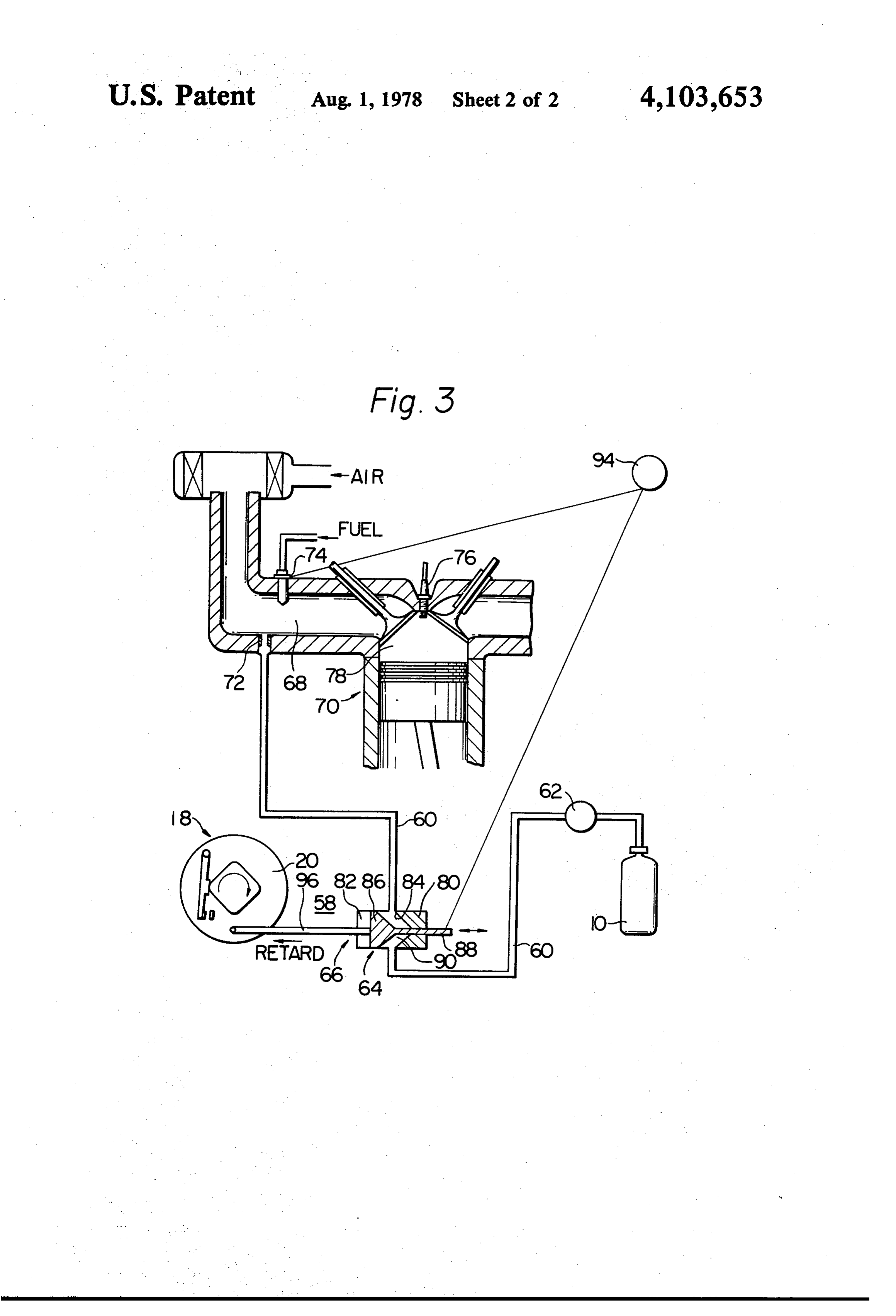
CONTROLLING IGNITION TIMING OF AN FIG. 2 is a schematic view of a first preferred em NTERNAL COMBUSTON ENGINE bodiment of an ignition timing control apparatus ac
BACKGROUND OF THE INVENTION FIG. 3 is a schematic view of a second preferred The present invention relates generally to controlling embodiment of an ignition timing control apparatus the ignition timing of a spark ignition type internal com according to the invention. 1... . . . " bustion engine run on a lean air-hydrocarbon fuel mix DESCRIPTION OF THE PREFERRED ture which is supplied with hydrogen as an auxiliary 10 EMBODIMENTS fuel in addition to the hydrocarbon fuel and particularly to a method and an apparatus in which the ignition Referring to FIG. 1 of the drawings, there is shown timing of an engine of this type is controlled in accor the relationship between the air-fuel ratio of the air-fuel dance with the amount of hydrogen supplied to the mixture of an engine and the optimum ignition timing engine. 15 advance of the engine which is stated in the introduc As a solution to the problem of reducing the produc tion of the specification and which results from the tion of air pollutants such as hydrocarbons (HC), car experiment.
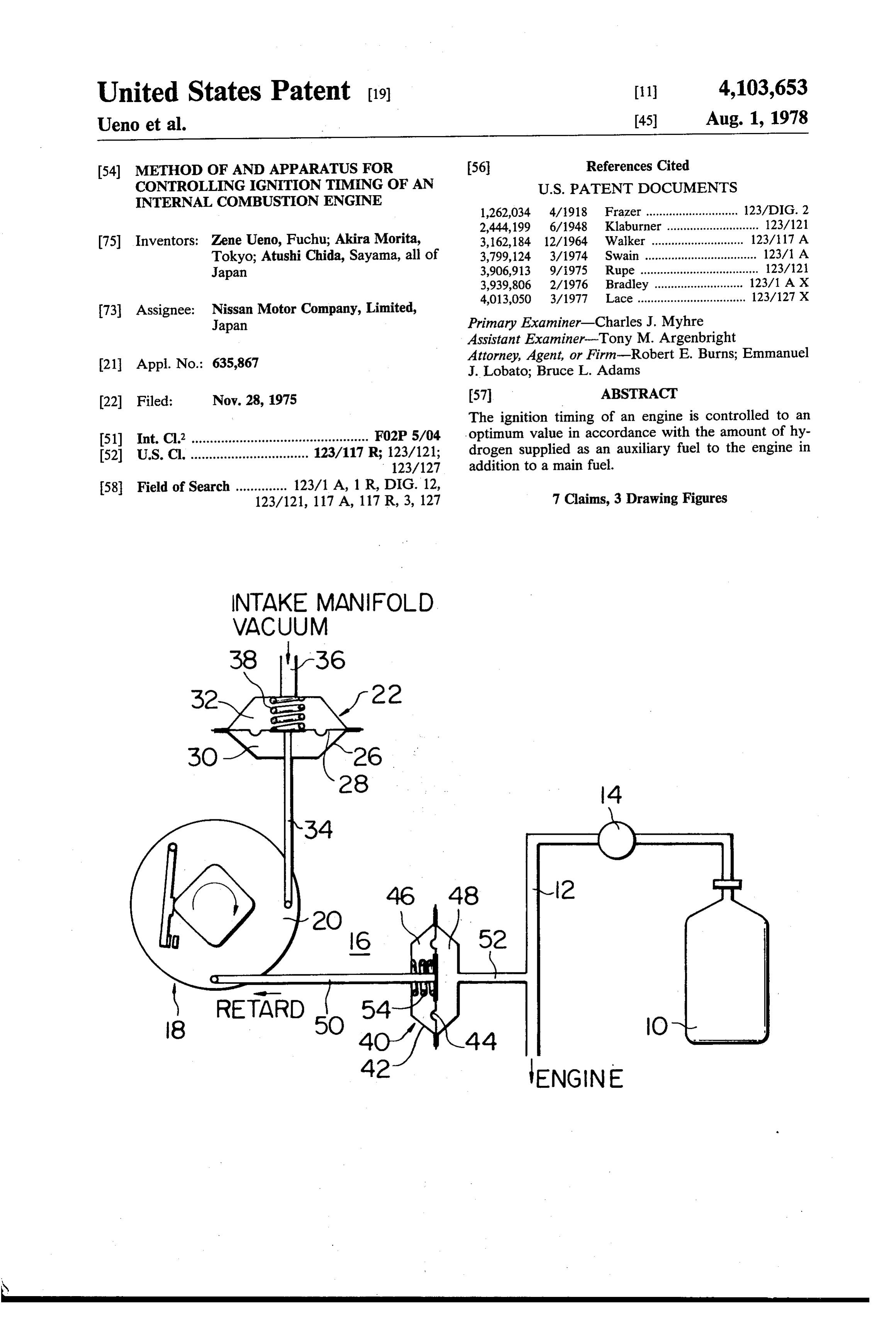
bon monoxide (CO) and nitrogen oxides (NOx) con Referring to FIG. 2 of the drawings, an ignition tim tained in exhaust gases discharged from an internal ing control apparatus according to the invention is combustion engine, it is well known in the art to set the 20 shown as comprising a source of hydrogen such as, for air-hydrocarbon fuel mixture of the engine considerably example, a container 10 storing hydrogen gas under lean and concurrently to supply the engine with hydro pressure which is supplied as an auxiliary fuel to an gen to complement the hydrocarbon fuel thereof. In this internal combustion engine (not shown) in addition to a instance, the engine has an optimum ignition timing or main fuel such as a hydrocarbon fuel. This is to supply advance at which the output of the engine is maximized 25 the engine with a considerably lean air-hydrocarbon and the air pollutant content in the engine exhaust gases fuel mixture to reduce the contents of air pollutants is minimized and which varies with the ratio of the such as hydrocarbons (HC), carbon monoxide (CO) and amount of hydrogen supplied to the engine to that of nitrogen oxides (NOx) in exhaust gases discharged from the hydrocarbon fuel, for example, gasoline, supplied the engine. A conduit 12 leads from the source 10 of thereto. 30 hydrogen to an induction passage or system (not An experiment confirmed the fact that the optimum shown) or a combustion chamber (not shown) of the ignition advance of an internal combustion engine is engine for supplying hydrogen thereto. A pressure re reduced and increased in accordance with sensed or ducing and flow control valve 14 is disposed in the controlled increases and decreases in the amount of passage 12 to adjust or meter to a predetermined or hydrogen supplied to the engine relative to that of the 35 desired value in known manner the ratio of the flow rate hydrocarbon fuel supplied thereto, respectively. The of hydrogen to the flow rate of the hydrocarbon fuel experiment particularly revealed the following facts: fed to the engine.
(1) Optimum or ideal vacuum and centrifugal ad The ignition timing control apparatus, generally des vance characteristics of the engine supplied with ignated by the reference numeral 16, is also shown as hydrogen are substantially similar respectively to 40 comprising or being combined with an ignition distribu those of an engine supplied with no hydrogen. tor 18 for controlling the ignition timing of the engine (2) Under the condition that engine intake manifold and having a centrifugal advance mechanism and a vacuum is constant, when an air-hydrocarbon fuel vacuum advance mechanism. The ignition distributor ratio (AVF) of the air-hydrocarbon fuel mixture of 18 also has a breaker plate 20 rotatable in opposite direc the engine is varied by making the flow rate of 45 tions and reduces and increases the ignition advance or hydrogen supplied to the engine constant and by retard and advance the ignition timing of the engine varying the flow rate of hydrocarbon fuel supplied when the breaker plate 20 is rotated, for example, clock to the engine, the optimum ignition advance of the wise and counterclockwise in the drawing, respec engine is increased as the air-hydrocarbon fuel tively.
ratio is increased. 50 A first control device 22 is connected to the breaker
SUMMARY OF THE INVENTION
plate 20 for controlling the ignition timing of the engine in accordance with vacuum in an intake manifold (not
It is, therefore, an object of the invention to provide shown) of the engine or the induction passage at a loca a method of and an apparatus for controlling the igni tion downstream of a throttle valve (not shown) of the tion timing of an internal combustion engine, supplied 55 engine. The first control device 22 is a conventional with a lean air-hydrocarbon fuel mixture and hydrogen, diaphragm assembly and comprises a housing 26, a to an optimum value in accordance with the amount of pressure sensitive deformable member such as a flexible hydrogen supplied to the engine so that the output of diaphragm 28 dividing the interior of the housing 26 the engine is maximized and the content of air pollutants into first and second chambers 30 and 32, and an operat in exhaust gases of the engine is minimized. 60 ing rod 34 fixedly secured at one end to the diaphragm BRIEF DESCRIPTION OF THE DRAWINGS 28 and operatively connected at the other end to the breaker plate 20. The first chamber 30 communicates
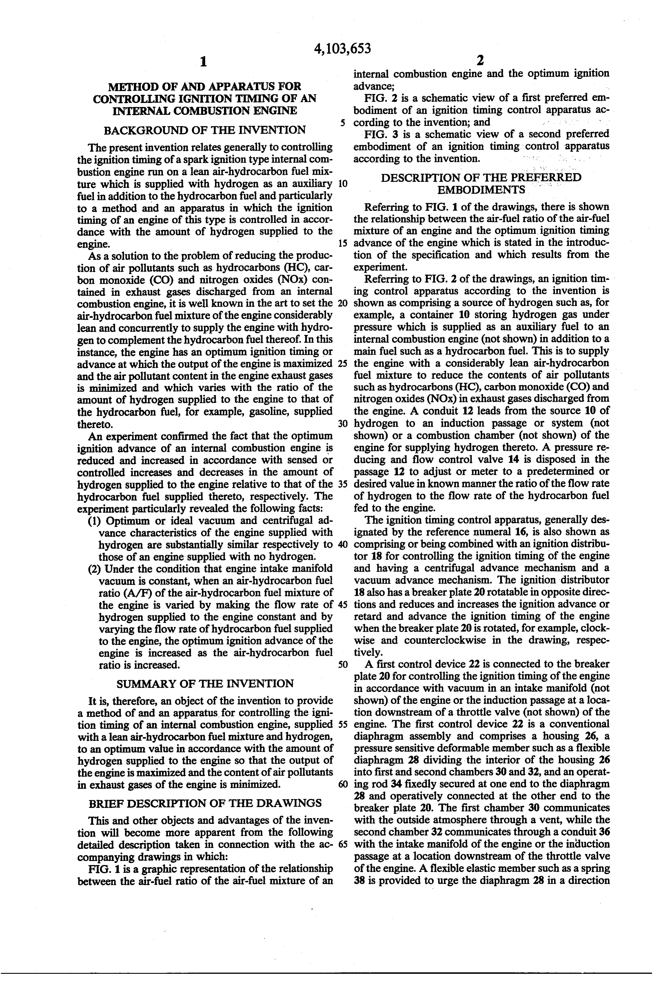
This and other objects and advantages of the inven with the outside atmosphere through a vent, while the tion will become more apparent from the following second chamber 32 communicates through a conduit 36 detailed description taken in connection with the ac- 65 with the intake manifold of the engine or the induction companying drawings in which: passage at a location downstream of the throttle valve FIG. 1 is a graphic representation of the relationship of the engine. A flexible elastic member such as a spring between the air-fuel ratio of the air-fuel mixture of an 38 is provided to urge the diaphragm 28 in a direction
Page 5
opposed by the pressure in the first chamber 30. The As shown in FIG. 3, the conduit 60 leads from a diaphragm 28 is moved to cause the ignition distributor source 10 of hydrogen to an induction passage 68 of the 18 to advance and retard the ignition timing of the en engine 70 for supplying hydrogen thereto. An orifice 72 gine in response to increases and decreases in the vac is formed in the passage 60 and opens into the induction uum in the induction passage at a location downstream passage 68. The engine 70 includes a fuel injection valve of the throttle valve, respectively. 74 positioned at the induction passage 68 for injecting A second control device 40 is connected to the the main fuel thereinto, and a spark plug 76 positioned breaker plate 20 for controlling the ignition timing of in a combustion chamber 78 of the engine 70. the engine in accordance with the amount of hydrogen 10 The flow control valve 64 is disposed in the conduit supplied to the engine through the conduit 12. The 60 between the pressure reducing valve 62 and the second control device 40 comprises a housing 42, a induction passage 68 and constitutes a part of the second pressure sensitive deformable member such as a flexible control device 66. The flow control valve 64 is a lift or diaphragm 44 which divides the interior of the housing tappet with a valve and comprises a housing 80 formed therein cavity 82 into which the conduit 60 opens, a 42 into first and second chambers 46 and 48, and an 15 valve seat 84 formed in the cavity 82, a valve head 86 operating rod 50 fixedly secured at one end to the dia slidably fitted in the cavity 82, and a valve rod 88 ex phragm 44 and operatively connected at the other end tending from the valve head 86 externally of the hous to the breaker plate 20. The first chamber 46 communi ing 80. The valve head 86 is movable toward or away cates with the outside atmosphere through a vent, while the second chamber 48 communicates with the conduit 20 from the valve seat 84 to vary the opening degree 90 of 12 through a conduit 52. The second chamber 48 is the valve 64. The fuel injection valve 74 and the valve rod 88 of the flow control valve 64 are connected to or located with respect to the ignition distributor 18 so that cooperate with for example, an accelerator pedal 94 of the diaphragm 44 is moved to cause the ignition distrib the engine 70 so that the valve 64 is opened and closed utor 18 to retard and advance the ignition timing of the in synchronism with the fuel injection valve 74 to con engine in response to increases and decreases in the 25 trol to a predetermined or desired value the ratio of the pressure of hydrogen in the second chamber 48, respec amount or flow rate of hydrogen supplied to the engine tively. A flexible elastic member such as a spring 54 is 70 to the amount or flow rate of the main fuel injected provided to urge the diaphragm 44 in a direction op through the fuel injection valve 74 to the posed by the pressure of hydrogen in the second cham pressure reducing valve 62 is disposed in engine the
conduit 60 ber 48. 30 at a location upstream of the flow control valve 64 for The ignition timing control apparatus 16 thus far maintaining the pressure of the hydrogen supplied described is operated as follows:
When the amount of hydrogen supplied to the engine thereto at a predetermined value. The second control device 66 is operable to cause the is increased by the operation of the flow control valve ignition distributor 18 to control the ignition timing of 14 in known manner such as, (e.g., by an accelerator 35 the engine 70 in accordance with the degree of opening linked to valve 14), the pressure of hydrogen in the of the flow control valve 64 and comprises the flow conduit 12 is increased to move the diaphragm 44 and control valve 64 and an operating stem 96 fixedly se the operating rod 50 leftward in the drawing so that the cured at one end to the valve head 86 and operatively breaker plate 20 is rotated clockwise to retard the igni connected at the other end to the breaker plate 20 of the tion timing of the engine. On the contrary, when the 40 ignition distributor 18. The valve head 86 is located amount of hydrogen supplied to the engine is reduced, with respect to the ignition distributor 18 so that the the pressure of hydrogen in the conduit 12 is reduced to valve head 86 operates the ignition distributor 18 move the diaphragm 44 and the operating rod 50 right through rod 96 to cause it to retard and advance the ward in the drawing so that the breaker plate 20 is ignition timing of the engine 70 in accordance with rotated counterclockwise to advance the ignition timing 45 increases and decreases in the degree of opening of the of the engine. Thus, an optimum ignition timing of the flow control valve 64, respectively. engine is maintained to maximize the output perfor The ignition timing control apparatus 58 thus far mance of the engine and to minimize the content of air described in operated as follows:
pollutants in the engine exhaust gases. When the flow control valve 64 is moved in a direc Referring to FIG.3 of the drawings, there is shown a 50 tion to increase the amount of hydrogen supplied to the second preferred embodiment of an ignition timing engine 70 in accordance with an increase in the amount control apparatus according to the invention which is of the main fuel supplied to the engine 70, that is, a applied to an internal combustion engine 70 of a fuel decrease in an air-hydrocarbon fuel ratio, through the injection type. The ignition timing control apparatus, fuel injection valve 74, the operating rod 96 is moved generally designated by the reference numeral 58, is 55 leftwards in the drawing so that the breaker plate 20 is different from the ignition timing control apparatus 16 rotated clockwise to retard the ignition timing of the shown in FIG. 2 in that it comprises a passage 60; a engine 70. On the contrary, when the opening degree of pressure reducing valve 62, a flow control valve 64; and the valve 64 is reduced to reduce the amount of hydro a second control device 66 in place of the passage 12, gen supplied to the engine 70 in accordance with a the flow control valve 14 and the first and second con decrease in the amount of the main fuel supplied to the trol devices 22 and 40 of the ignition timing control engine 70, that is, an increase in the air-hydrocarbon apparatus 16. In FIG. 3, like component elements are fuel ratio, the operating rod 96 is moved rightwards in designated by the same reference numerals as those used the drawing so that the breaker plate 20 is rotated coun in FIG.2. Since the engine 70 is provided with no throt terclockwise to advance the ignition timing of the en tle valve, air is freely drawn into the engine irrespective 65 gine 70. Thus, the ignition timing of the engine 70 is of the output of the engine 70 and the engine output is controlled to an optimum value as a function of the controlled by the amount of hydrocarbon fuel injected amounts of the main fuel and hydrogen supplied to the to the engine or an air-hydrocarbon fuel ratio. engine 70.
Page 6
It will be appreciated that the invention provides a defining means for providing communication between method and an apparatus in which the ignition timing of said first passage-defining means and said fluid chamber an internal combustion engine is controlled to an opti for variably moving said diaphragm in accordance with mum value in accordance with the amount of hydrogen the amount of said hydrogen fed to said engine, and an . supplied as an auxiliary fuel to the engine in addition to operating rod for operatively connecting said dia a main fuel so that the output of the engine is maximized phragm to said ignition distributor for varying the igni and the content of air pollutants in exhaust gases of the tion timing of said engine in accordance with the posi engine is minimized. tion of said diaphragm so that the ignition timing of said What is claimed is: engine is variably retarded and variably advanced in 1. An ignition timing control apparatus in combina 10 accordance with variable increases and variable de tion with an internal combustion engine including an creases in the amount of said hydrogen fed to said en ignition distributor, a source of auxiliary fuel, and con gine, respectively.
duit means for providing communication between said 5. An ignition timing control apparatus in combina source of auxiliary fuel and said engine for feeding aux tion with an internal combustion engine including an iliary fuel thereinto in addition to a main fuel, said appa 15 ignition distributor, a source of hydrogen, conduit ratus comprising variable control means for communi means for providing communication between said cating with said conduit means and the position of source of hydrogen and said engine for feeding hydro which is varied in accordance with the amount of said gen as an auxiliary fuel thereinto in addition to a main auxiliary fuel fed to said engine, and connecting means fuel, and a variable flow control valve movably dis for operatively connecting said variable control means 20 posed in said conduit means for variably controlling the to said ignition distributor for variably controlling the flow of said hydrogen fed to said engine, said apparatus ignition timing of said engine in accordance with the comprising an operating rod for operatively connecting position of said variable control means. said flow control valve to said ignition distributor for 2. An ignition timing control apparatus in combina varying the ignition timing of said engine in accordance tion with an internal combustion engine including an 25 with the position of said variable flow control valve. ignition distributor, a source of hydrogen, and conduit 6. An ignition timing control apparatus in combina means for providing communication between said tion with an internal combustion engine including an source of hydrogen and said engine for feeding hydro ignition distributor, a source of hydrogen, and conduit gen as an auxiliary fuel thereinto in addition to a main means for providing communication between said fuel, said apparatus comprising variable control means 30 source of hydrogen and said engine for feeding hydro for communicating with said conduit means and the gen as an auxiliary fuel thereinto in addition to a main position of which is varied in accordance with the fuel, said apparatus comprising variable control means amount of said hydrogen fed to said engine, and con for communicating with said conduit means and the necting means for operatively connecting said control position of which is varied in accordance with the means to said ignition distributor for variably control 35 amount of said hydrogen fed to said engine, and con ling the ignition timing of said engine in accordance necting means for operatively connecting said control with the position of said variable control means. means to said ignition distributor for variably control 3. An ignition timing control apparatus in combina ling the ignition timing of said engine in accordance tion with an internal combustion engine including with the position of said variable control means; said means for defining an intake passageway having a throt 40 variable control means comprising a housing, a flexible tle valve rotatably mounted therein, an ignition distribu diaphragm dividing the interior of said housing into a tor having a breaker plate, a diaphragm assembly in first chamber communicating with the outside atmo cluding a flexible diaphragm having a fluid chamber on sphere and a second chamber communicating with said a side thereof, a connecting rod operatively connecting conduit means, an operating rod fixedly secured at one said diaphragm to said breaker plate, passage means for 45 end to said diaphragm and operatively connected at the providing communication between said fluid chamber other end to said ignition distributor, said second cham and said intake passageway downstream of said throttle ber being located with respect to said ignition distribu valve, a source of hydrogen, and conduit means for tor so that said diaphragm is moved to cause said igni providing communication between said source of hy tion distributor to retard and advance the ignition tim drogen and said engine for feeding hydrogen as an aux 50 ing of said engine in response to increases and decreases iliary fuel thereinto in addition to a main fuel, said appa in the pressure of hydrogen in said second chamber, ratus comprising variable control means communicat respectively, and biasing means urging said diaphragm ing with said conduit means and the position of which is in a direction opposed by the pressure of hydrogen in varied in accordance with the amount of said hydrogen said second chamber.
fed to said engine, and connecting means for opera 55 7. An ignition timing control apparatus in combina tively connecting said control means to said breaker tion with an internal combustion engine including an plate for variably controlling the ignition timing of said ignition distributor, a source of hydrogen, and conduit engine in accordance with the position of said variable means for providing communication between said control means. source of hydrogen and said engine for feeding hydro 4. An ignition timing control apparatus in combina gen as an auxiliary fuel thereinto in addition to a main tion with an internal combustion engine including an fuel, said apparatus comprising variable control means ignition distributor, a source of hydrogen, and first for communicating with said conduit means and the passage-defining means for providing communication position of which is varied in accordance with the between said source of hydrogen and said engine for amount of said hydrogen fed to said engine, and con feeding hydrogen as an auxiliary fuel thereinto in addi necting means for operatively connecting said control tion to a main fuel, said apparatus comprising a dia means to said ignition distributor for variably control phragm assembly comprising a flexible diaphragm hav ling the ignition timing of said engine in accordance ing a fluid chamber on a side thereof, second passage with the position of said variable control means, said
Page 7
variable control means comprises a variable flow con to said ignition distributor so that said ignition distribu trol valve disposed in said conduit means, said variable tor is caused to retard and advance the ignition timing flow control valve comprising a valve seat and a valve of said engine in accordance with increases and de head movable with respect to said valve seat to vary the degree of opening of said variable flow control valve, creases in the degree of opening of the variable flow and an operating rod fixedly secured at one end to said control valve, respectively.
valve head and operatively connected at the other end
Provenance
- Collection
- Cited prior art
- Original PDF
- patentimages.storage.googleapis.com →
- Filed
- 1975-11-28
- Pages
- 7
- Method
- pdftotext (the PDF's own text layer) + pdftoppm 300dpi page scans
- Source
- Google Patents bibliographic record
- Granted
- 1978-08-01
- Inventors
- Zene Ueno; Akira Morita; Atushi Chida; Nissan Motor Co Ltd
- Transcribed from
- patentimages.storage.googleapis.com →