patent · US5445019
Internal combustion engine with on-board diagnostic system for detecting impaired fuel injectors
29 August 1995
Page 1 — bibliographic record
United States Patent (19) 11 Patent Number: 5,445,019 Glidewell et al. 45 Date of Patent: Aug. 29, 1995 54 INTERNAL COMBUSTION ENGINE WITH FOREIGN PATENT DOCUMENTS
ON-BOARD DAGNOSTIC SYSTEM FOR
DETECTING MPARED FUEL INJECTORS 0501459 9/1992 European Pat. Off. .
75) Inventors: John M. Glidewell, Dearborn; 5594428 2/1982 Japan. Granger K. Chui, Dearborn Heights; 56105821 1/1983 Japan.
Woong-Chul Yang, Ann Arbor, all of 61290218 6/1988 Japan.
Mich. 61295866 6/1988 Japan .
73) Assignee: Ford Motor Company, Dearborn, 224.5382 1/1992 United Kingdom . Mich. Primary Examiner-Herbert Goldstein
Assistant Examiner-Joseph L. Felber 21 Appl. No.: 47,905 Attorney, Agent, or Firm-Peter Abolins; Roger L. May 22 Filed: Apr. 19, 1993 57 ABSTRACT 51) Int. Cl. ............................................. F02M 65/00 The present invention is directed to an on-board diag 52 U.S. Cl. .................. ... 73/119 A; 123/387 nostic system for detecting impaired fuel injectors in an 58) Field of Search ............................ 73/119 A, 49.7; internal combustion engine during engine operation. A 123/387, 494 fuel injector control means is provided for individually actuating fuel injectors operatively connected to a fuel 56) References Cited rail. Pressure sensor means are mounted to the fuel rail for sensing transient fuel pressure waves resulting from
3,919,885 11/1975 Kareit. cessing means are provided for processing pressure 4,257,260 3/1981 Beatson et al. . signals from the pressure sensor means. The output 4,261,209 4/1981 Hatsuno et al. . signal from the signal processing means corresponds to 4,696,275 9/1987 Kushi et al. . the fuel flow rate through the fuel injectors. Such out 4,791,810 12/1988 Old et al. . put signal can be used to alert an engine operator to an 4,899,713 2/1990 Nakamura. impaired fuel injector and/or can be provided to the 4,930,482 6/1990 Kako. fuel injector control means for adjusting the duration of
5,020,362 5/1991 Hart et al. . injector actuation to achieve a desired fuel flow quan 5,058,547 10/1991 Morikawa .................... 73/19 AX tity per individual actuation.
5,218,941 6/1993 Suzuki et al. ................... 123/494 X 13 Claims, 4 Drawing Sheets
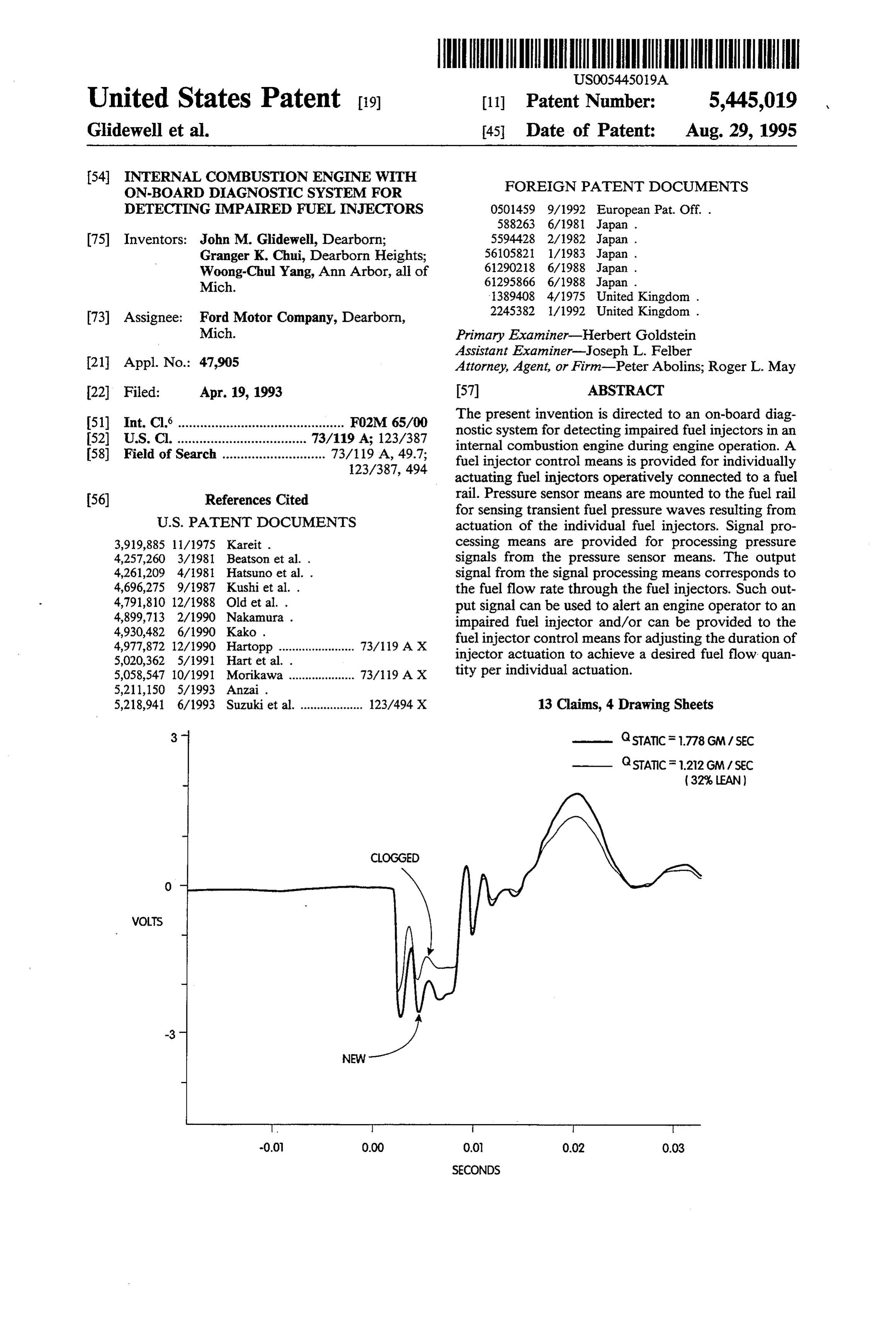
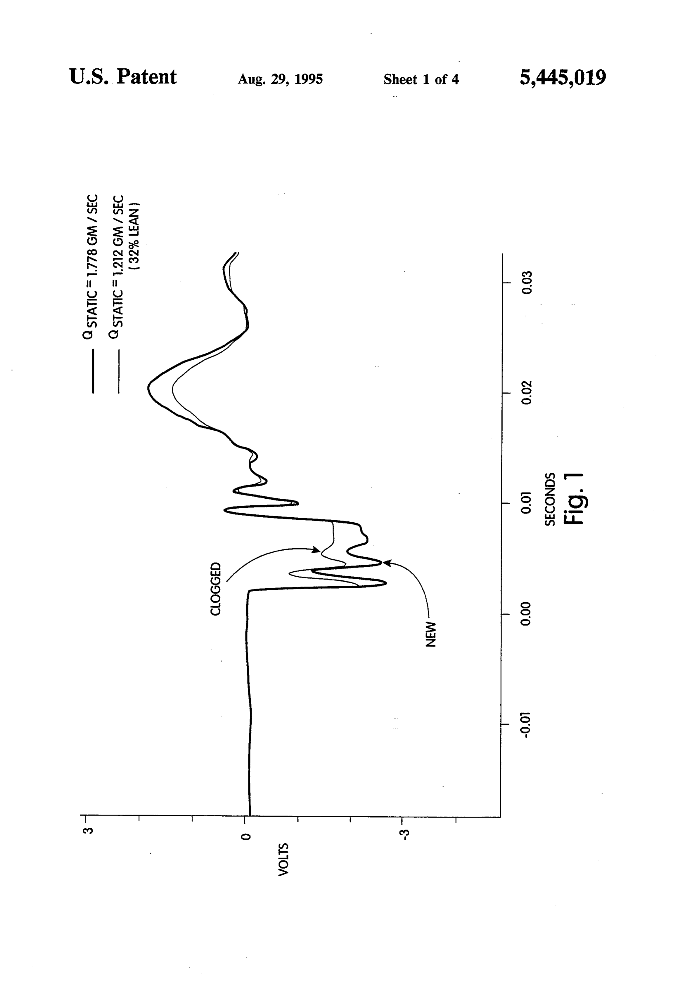
GSTATICF .212 GM / SEC
WOLS
0.0 0.00 O.O. 0.02 0.03
SECONDS
Page 2
Drawing sheet — no readable text.
Page 3
Drawing sheet — no readable text.

Page 4
Drawing sheet — no readable text.
Page 5
Drawing sheet — no readable text.
Page 6
been found that such analysis of fuel pressure transients
INTERNAL COMBUSTION ENGINE WITH acquired by a single pressure transducer mounted on ON-BOARD DAGNOSTIC SYSTEM FOR the engine fuel rail can accurately predict dynamic fuel DETECTING IMPARED FUEL INJECTORS flow of individual fuel injectors spaced along the fuel rail and so identify impaired fuel injectors.
INTRODUCTION In accordance with the present invention, an internal The present invention is directed to a diagnostic sys combustion engine is provided with an on-board diag tem for an internal combustion engine to detect im nostic system for detecting impaired fuel injectors dur paired fuel injectors. More specifically, the invention is ing engine operation. Such an engine and on-board directed to an on-board diagnostic system for detecting 10 diagnostic system comprise fuel supply means for sup impaired fuel injectors during engine operation. plying liquid fuel under pressure to the combustion
BACKGROUND OF THE INVENTION
cylinders of the engine, including a plurality of fuel injectors operatively connected to a fuel rail. Fuel injec
It has long been the practice to dismantle an internal tor control means are provided for individually actuat combustion engine to determine the condition of its 15 ing the fuel injectors to pass fuel from the fuel rail dur components. It is becoming increasingly desirable, ing a controlled actuation period. Pressure sensor means however, to provide on-board diagnostic means for senses fuel pressure in the fuel rail and generates a pres components which have a major impact on certain sure signal which varies with the pressure sensed. The critical engine performance criteria. This is particularly 20 pressure sensor means may employ a pressure trans true in the motor vehicle industry, where high precision ducer comprising, for example, a pressure responsive in the control of fuel flow has become essential to vari diaphragm exposed to the fuel in the fuel rail and a ous present and planned engine management features signal conditioner to generate a continuous analog volt designed to meet increasingly strict emissions, perfor age output signal. The pressure signal from the pressure mance, drivability, and maintenance objectives. Thus, it sensor means will vary with time in response to tran is now well known how to adjust the fuel flow to the 25 sient fuel pressure fluctuations in the fuel rail resulting cylinders of an engine to maintain desired fuel/air mix from actuation of each of the fuel injectors. These mea ture ratio for meeting engine emission requirements by surable changes in fuel rail pressure resulting from actu electronically controlling the actuation timing and du ation of each individual fuel injector reliably corre ration of the engine's fuel injectors. Electronic fuel sponds to flow rate through that injector. Thus, the injector controls are presently available and in use, 30 change in value of the pressure signal is measured, and especially in the engines of more advanced motor vehi the difference value reliably corresponds to fuel flow cles. The control function may be incorporated into an rate during actuation.
electronic engine control (EEC) module performing a represents a significant Inadvance fact, the present invention in electronic engine variety of engine control functions. In accordance with control in part for its recognition of the useful corre such known systems, the timing of injector actuation is spondence of such measurable transient
fuel pressure controlled by the timing of the corresponding actuation waves in the fuel rail, especially low-frequency pressure signal sent by the control module. The duration of injec tor actuation, during which fuel is passed through the waves, to the actual fuel flow rate of a fuel injector injector from a fuel rail or like fuel supply means, is during its actuation and for its presently disclosed means and method of detecting impaired fuel injectors controlled by the duration of the actuation signal from during engine operation using pressure signals corre the control module, that is, by the pulse width of the signal. sponding to each measured transient fuel pressure Reliably controlling a fuel injector's fuel supply by Wave.
controlling its actuation signal pulse width requires that Signal processing means are provided for processing the fuel injector be performing at or near its specified 45 the pressure signals from the pressure sensor means and flow rate when open. A fuel injector may become for generating an output signal in response thereto. The clogged, however, over a period of use, potentially signal processing means preferably develops an average resulting in decreased engine efficiency, increased emis pressure signal value corresponding to a non-actuation sion of undesirable combustion products, etc. Thus, in period and an average pressure signal value correspond support of maintaining the efficacy of electronic engine 50 ing to an actuation period. For a typical application of management devices adapted to control air/fuel ratio the invention in a motor vehicle engine, the signal pro by controlling the actuation of fuel injectors, it is now cessing means may take the average of one hundred recognized to be highly desirable to provide means for signal values taken over a two or three millisecond detecting clogged or otherwise impaired fuel injectors. period for the non-actuation value, and use the same In particular, it is seen to be especially desirable to 55 sampling rate over a three to five millisecond period for provide an on-board diagnostic system to periodically the actuation value.
test an engine's fuel injectors during engine operation In certain particularly preferred embodiments of the without requiring disassembly of the engine. invention, the on-board diagnostic system is integrated
SUMMARY OF THE INVENTION
with adaptive air/fuel control means. In accordance with such embodiments, the actuation period of the fuel
The on-board diagnostic system of the present inven injectors may be adjusted as their conditions change tion employs analysis of fuel pressure transients initiated with age. Most notably, the adaptive air/fuel control by the fuel injection event, that is, by fuel injector actu means may increase the actuation period of a fuel injec ation. It should be understood that reference herein to tor to compensate for its decreased fuel flow rate as a actuation of a fuel injector for a controlled actuation 65 result of clogging or like impairment. Thus, preferably, period is meant to include the deactuation of the fuel an output signal of the signal processing means corre injector at the end of that time period. In accordance sponding to the difference between the actuation value with preferred embodiments of the invention, it has and the non-actuation value (and, hence, to the fuel
Page 7
flow rate through the injector in question, as discussed DETAIL DESCRIPTION OF CERTAIN above) is sent to the fuel injector control means. Since PREFERRED EMBODIMENTS the output signal of the signal processing means corre sponds to flow rate through a given injector, the fuel While the present invention is applicable generally to injector control means can rely on the output signal to 5 any internal combustion engine burning liquid fuel sup determine and control fuel flow quantity. That is, the plied to fuel injectors via a fuel rail, it is particularly fuel injector control means preferably is adapted to advantageous for gasoline burning multicylinder en adjust the actuation period of each individual fuel injec gines, especially motor vehicle engines. Accordingly, tor based on its fuel flow rate as indicated by the output 10 without intending to limit the scope of the invention, signal received from the signal processing means, typi burningthe discussion below will focus primarily on gasoline cally by increasing or decreasing the pulse width of its nostics ofmotor vehicle engines for which on-board diag various engine performance characteristics is actuation signal to the injector, to yield the desired total becoming extremely fuel flow quantity for each actuation of each injector. addresses this need byimportant.providing The present invention an on-board diagnostic
Thus, in a preferred embodiment in which a fuel injec 15 system for detecting impaired fuel injectors. Fuel injec tor becomes clogged, the output signal for that fuel tor clogging can occur through normal engine use and injector from the signal processing means would indi can cause rough idle and lack of power. The on-board cate reduced fuel flow rate, and the fuel injector control diagnostic system of the invention can detect the onset means would send actuation signals to that injector of injector clogging on a running engine. Preferred having a correspondingly enlarged pulse width to 20 embodiments of the on-board diagnostic system of the lengthen the actuation period during which the injector invention can identify specific impaired injectors, thus is open to pass fuel from the fuel rail. avoiding the need to replace the engine's complete set An operator signal means may be provided for gener of fuel injectors and/or facilitating remedial action by ating a signal to an operator of the engine, for example adaptive fuel injector control means to achieve desired a motor vehicle driver. Thus, the engine operator may 25 total fuel flow with each injector actuation. As to the be alerted of an impaired injector and undertake pre latter, more specifically, an output signal from the on ventive maintenance, such as the use of detergent fuel board diagnostic system can serve as an input signal to or the addition of fuel injector cleaning additives. the electronic engine control (EEC) for adaptive air/f- As noted above, variability of injector fuel delivery 30 uel ratio control, that is, to enable the EEC computer to due to clogging can significantly degrade the control of adjust injector actuation duration to compensate for reduced flow rate through the injector resulting from exhaust emissions, engine performance, etc. Hence, the clogging detection of flow deterioration due to injector clogging or like impairment. or the like by the on-board diagnostic system of this theThe graph in FIG. 1 shows pulse waveforms, that is, invention, which is able to carry out such detection 35 rail output signal from a pressure transducer sensing fuel during running of the engine, can help control exhaust injectors. Theobtained pressure, by testing new and clogged fuel graph plots the voltage of the output emissions and engine performance, and can be em signal from a pressure transducer mounted to a fuel rail. ployed in an adaptive strategy to manage fuel flow in an The pulse waveform was obtained using a pressure engine having degraded fuel injector performance. transducer having a variable voltage output signal pro These and other features and advantages of the present portional to pressure within the fuel rail. Zero volts invention will be better understood in view of the fol corresponds substantially to static equilibrium pressure lowing detailed description of certain preferred em within the fuel rail (established by a pressure regulator) bodiments. without fuel injector actuation. Given an actuation BRIEF DESCRIPTION OF THE DRAWINGS 45 commencing at time 0.00 on the graph, pressure in the fuel rail drops at the location of the pressure transducer
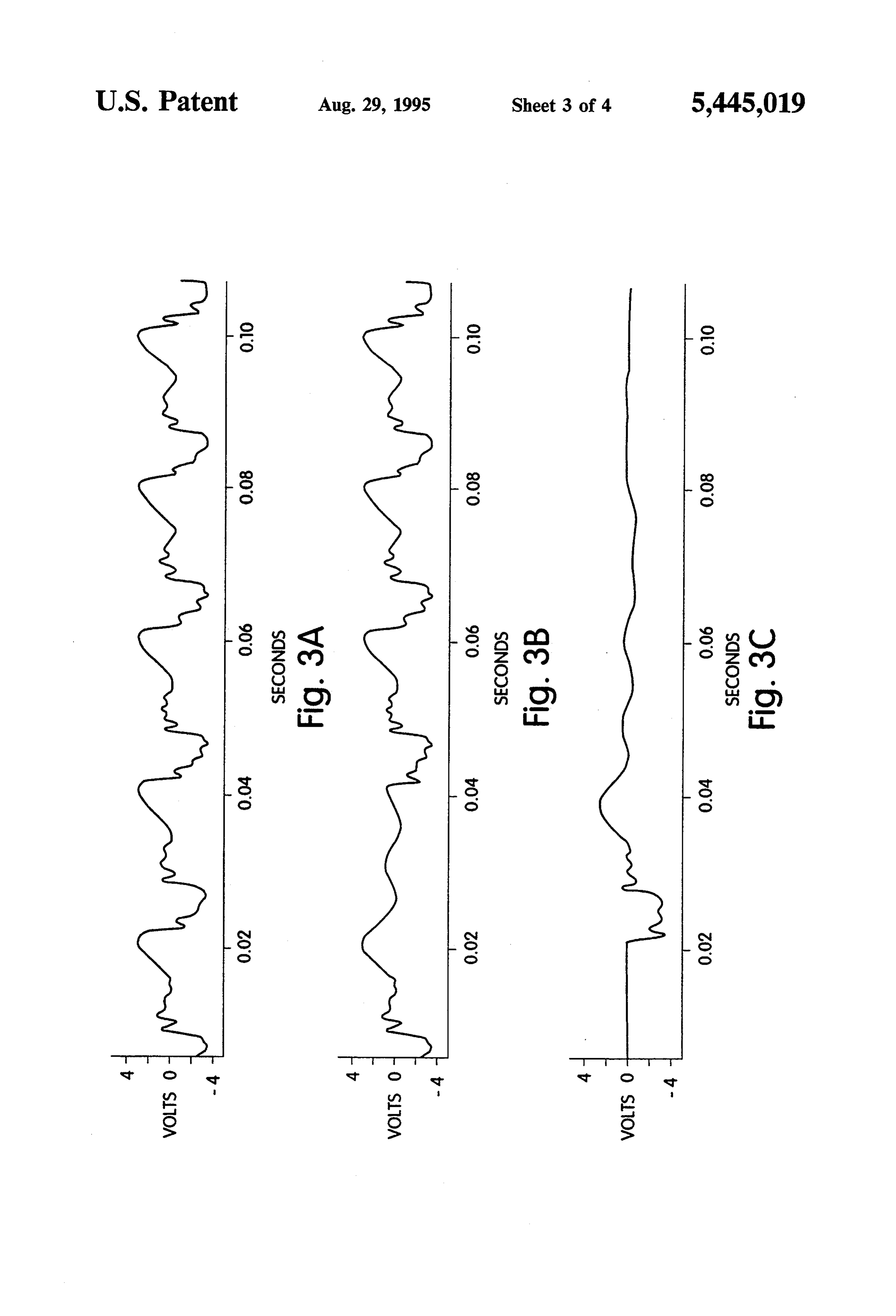
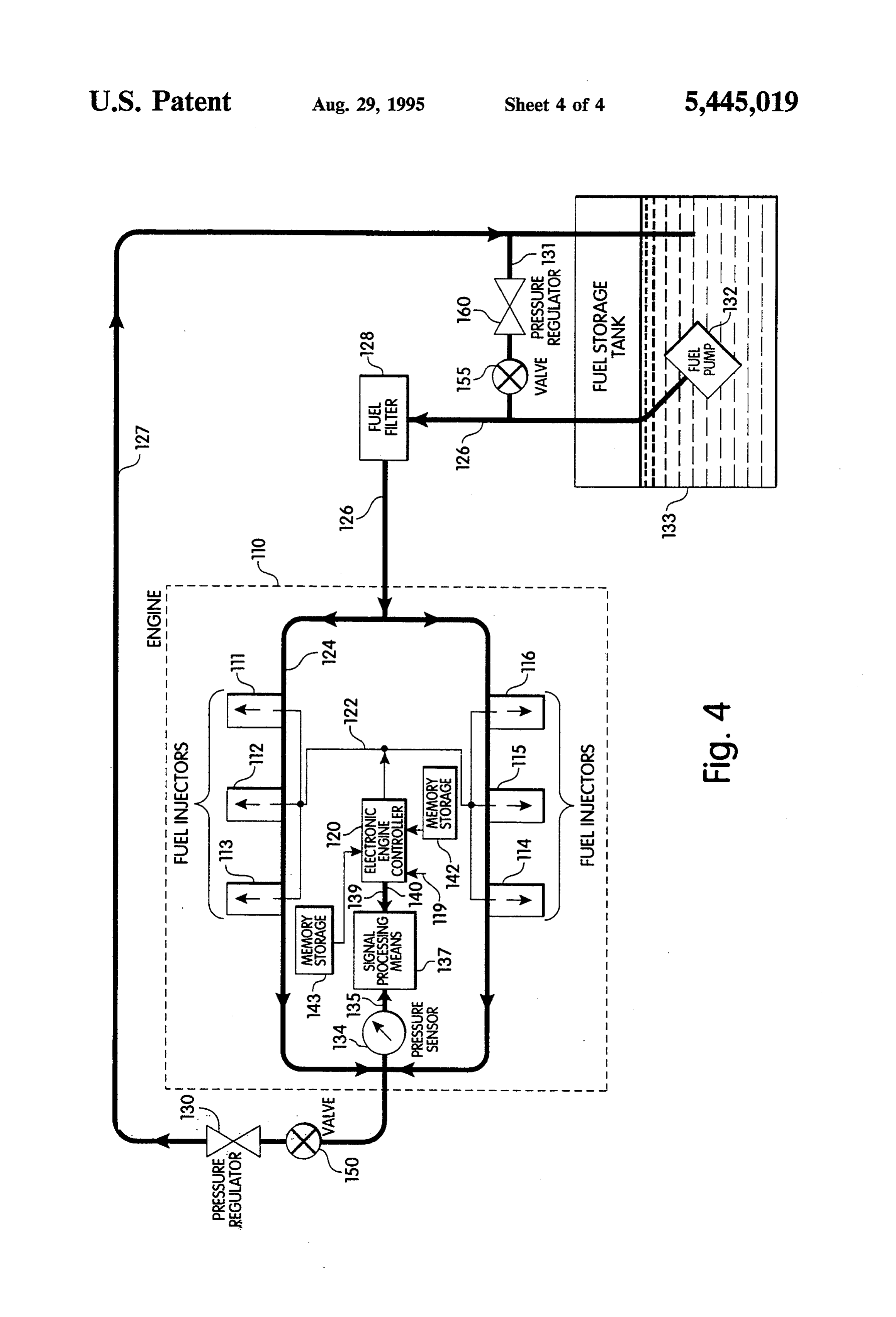
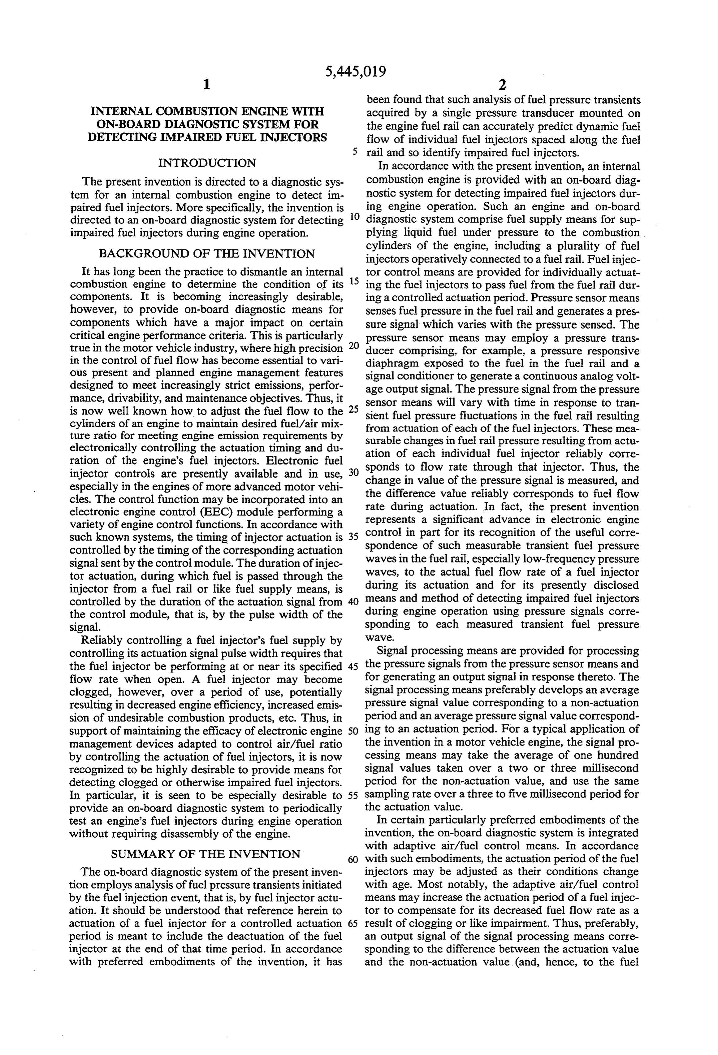
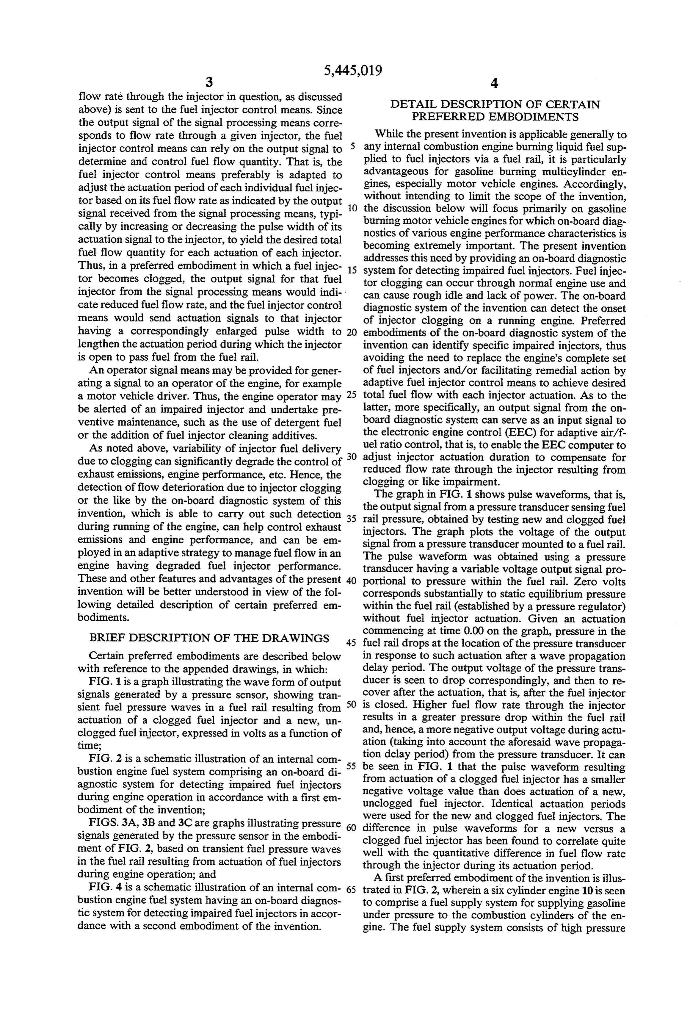
Certain preferred embodiments are described below in response to such actuation after a wave propagation with reference to the appended drawings, in which: delay period. The output voltage of the pressure trans FIG. 1 is a graph illustrating the wave form of output ducer is seen to drop correspondingly, and then to re signals generated by a pressure sensor, showing tran cover after the actuation, that is, after the fuel injector sient fuel pressure waves in a fuel rail resulting from 50 is closed. Higher fuel flow rate through the injector actuation of a clogged fuel injector and a new, un results in a greater pressure drop within the fuel rail clogged fuel injector, expressed in volts as a function of and, hence, a more negative output voltage during actu time; ation (taking into account the aforesaid wave propaga FIG. 2 is a schematic illustration of an internal com 55 tion delay period) from the pressure transducer. It can bustion engine fuel system comprising an on-board di be from seen in FIG. 1 that the pulse waveform resulting actuation of a clogged fuel injector has a smaller agnostic system for detecting impaired fuel injectors negative during engine operation in accordance with a first em uncloggedvoltage fuel value than does actuation of a new, injector. Identical actuation periods bodiment of the invention; were used for the new and clogged fuel injectors. The FIGS. 3A, 3B and 3C are graphs illustrating pressure 60 difference in pulse waveforms for a new versus a signals generated by the pressure sensor in the embodi clogged fuel injector has been found to correlate quite ment of FIG. 2, based on transient fuel pressure waves well with the quantitative difference in fuel flow rate in the fuel rail resulting from actuation of fuel injectors through the injector during its actuation period. during engine operation; and A first preferred embodiment of the invention is illus FIG. 4 is a schematic illustration of an internal com 65 trated in FIG. 2, wherein a six cylinder engine 10 is seen bustion engine fuel system having an on-board diagnos to comprise a fuel supply system for supplying gasoline tic system for detecting impaired fuel injectors in accor under pressure to the combustion cylinders of the en dance with a second embodiment of the invention. gine. The fuel supply system consists of high pressure
Page 8
electric Gerotor-type pump 32 delivering fuel from a In the preferred embodiment illustrated in FIG. 2, storage tank 33 through an inline fuel filter 28 to a fuel pressure sensor means 34 is mounted to fuel rail 24. charging manifold assembly 24 via solid and flexible Suitable pressure sensor means are commercially avail fuel lines. The fuel charging manifold assembly, com able and include, for example, variable reluctance, dif monly referred to as a fuel rail, supplies fuel to electronferential pressure transducers. Preferably the transducer ically actuated fuel injectors 11-16 mounted on an air has good transient response to low frequency transient intake manifold directly above each of the engine's pressure waves, low frequency here meaning 1 KHz or intake valves. Air entering the engine is measured by a lower. The pressure sensor means preferably also has a mass airflow meter. Air flow information and input high output signal with low susceptibility to electrical from other engine sensors 19 is used by an onboard 10 noise and good durability to withstand vibrations and engine electronic control computer 20 to calculate the shock experienced in a motor vehicle engine environ required fuel flow rate necessary to maintain a pre ment. Employing pressure sensor means having a trans scribed air/fuel ratio for a given engine operation. The ducer diaphragm vented on one side to atmosphere injectors, when energized, spray a predetermined quan allows gage measurement of pressure (PSIG). The out tity of fuel (if they are unclogged) in accordance with 15 put signal from the pressure transducer preferably is a engine demand, into the intake air stream. The duration continuous analog voltage out signal, where signal volt of the actuation period during which the injectors are age varies directly with fuel pressure. Zero voltage can energized, determined by the actuation signal pulse be set to the nominal fuel pressure established for the width, is controlled by the vehicle's EEC computer 20. fuel rail. The pressure signal from the pressure sensor Thus, the EEC computer serves as the fuel injector means 34 may further comprise signal conditioning control means, and, typically, performs various addi means. Thus, the pressure transducer may be connected tional engine control functions. by a shielded cable to a signal conditioner. Suitable The fuel injector is an electromechanical device that signal conditioners for various suitable pressure trans atomizes the fuel delivered to the engine. Injectors ducers are commercially available and will be apparent typically are positioned so that their tips direct fuel at 25 to those skilled in the art in view of the present disclo the engine intake valves. The valve body consists of a sure. In accordance with such preferred embodiment, solenoid actuated pintle or needle valve assembly that the transducer signal conditioner sources the pressure sits on a fixed size orifice. A constant pressure drop is transducer with excitation power and amplifies the maintained across the injector nozzles via a pressure transducer output. The resulting pressure signal, that is, regulator. An electrical signal from the EEC unit acti analog voltage output 35 of the pressure sensor means vates the solenoid, causing the pintle to move inward, 34 is, therefore, proportional to fuel rail pressure sensed off the seat, allowing fuel to flow through the orifice. by the pressure transducer.
Thus, the six fuel injectors 11-16 each includes a nozzle The pressure signal is input to signal processing assembly which may become clogged and provide re means 37 for generating an output signal in response duced fuel flow rate during actuation by its injector 35 thereto. Signal processing means 37 can be, for example, driver assembly in response to an actuation signal from a programmable waveformanalyzer, various models of the fuel injector control means. An injector would be which are commercially available and will be readily considered clogged or impaired for purposes of the apparent to those skilled in the artin view of this disclo present invention if it is performing below its intended sure. Such analyzers digitize and store analog voltage level, specifically, by passing less fuel to its respective signals, typically at a rate of about 100 kilosamples per combustion chamber during a given actuation period second. The signal processing means preferably is re than would a fully functioning (e.g., new) fuel injector. sponsive to a timing signal 39 from the fuel injector In the embodiment of FIG. 2, fuel injector control control means 20 to synchronize acquisition of pressure means 20 has injector signal output means 22 connected waveforms with the actuation of the individual injec to the injector drivers of the fuel injectors 11-16. In 45 tors. The delay between the sending of the actuation jector signals from fuel injector control means 20 con signal and the arrival at the pressure sensor means of the trol the sequence and timing of fuel injector actuation, resulting transient fuel pressure waveform is readily including the duration of the actuation period during obtained empirically for any given application of the which each fuel injector, in turn, is open to pass fuel invention (i.e., for any given engine arrangement). from fuel rail 24 to the respective combustion chamber. 50 Those skilled in the art will recognize that such propa A pressure regulator 30 is provided for regulating fuel gation delay will vary from injector to injector, depend pressure within fuel supply line 26 and, therefore, in fuel ing on such factors as the distance along a fuel rail rail 24. Pressure regulator 30 is located proximate to between the pressure sensor means and the individual fuel pump 32. That is, it is closer to fuel pump 32 than injector. The signal processing means 37 preferably to the fuel rail 24 and is upstream of the fuel filter 28. 55 takes multiple values of the pressure signal 35 over an Locating the pressure regulator 30 proximate to the fuel actuation sampling period initiated after the propaga pump is found to provide enhanced accuracy of pres tion delay time has passed following its receipt of the sure readings by pressure sensor means 34 mounted on timing signal 39 from the fuel injector control means 20. fuel rail 24. The fuel pressure regulator typically is a Averaging the multiple values sampled during such diaphragm operated relief valve with one side of the 60 actuation period yields an actuation value. In accor diaphragm sensing fuel pressure and the other side sub dance with this particular preferred embodiment of the jected to intake manifold pressure. The nominal fuel invention, the signal processing means also conducts a pressure is established by a spring preload applied to the non-actuation sampling period. That is it takes multiple diaphragm. Referencing one side of the diaphragm to values of the pressure signal over a non-actuation sam manifold pressure aids in maintaining a constant pres 65 pling period during which the pressure signal from the sure drop across the injectors. Fuel in excess of that transducer corresponds to the pressure in the rail sub used by the engine passes through the regulator and stantially unreduced by an injector actuation event. returns to the fuel tank 33 via shunt line 31. Averaging such multiple values yields a non-actuation
Page 9
value. The signal processing means then generates an propagation delay period) divided by the steady output signal 40 to the fuel injector control means 20 state pressure drop from the nominal fuel rail pres based on the difference between the actuation value and sure upon leaving the injector (100% unclogged) the non-actuation value. Without wishing to be bound full open with the pressure regulator fixed open at by theory, it is now understood that the output signal of 5 its pre-actuation setting (both of which pressure the signal processing means (essentially a A voltage drops are readily measured by routine flow stand value in the preferred embodiment discussed above) tests);
correlates well to static flow rate through the injector in a is the nominal fuel rail pressure; and question and, in turn, the static flow rate correlates well AV is the value of the output signal from the signal to dynamic flow rate. Thus, the value of output signal 10 processing means for a given actuation event, being 40 from the signal processing means corresponds to the equal to the measured voltage drop corresponding fuel flow rate through the individual injector in ques to the transient pressure drop, with a calibration of tion. As the injector becomes clogged the difference 1 PSI/volt.
between the actuation value and the non-actuation
It should be recognized that the wave form associ ated
Typically, the signal processing means will employ a pressure with a given injector actuation, as sensed by the test duration of two to three milliseconds, acquiring 100 interference sensor means, typically comprises a complex sample values of the pressure signal over such test per ing events ofpattern the generated by the opening and clos- .
injector and their associates echoes iod for determining the non-actuation value. The actua propagated in the fuel rail. Without tion value preferably is determined over a test period of 20 by theory, it is presently understoodwishing that the to be bound wave form three to five milliseconds at the same sampling rate used resulting from each individual injector actuation com for the non-actuation test period. bines substantially linearly with the waveforms gener The fuel injector control means 20 preferably com prises memory means 42, for example, a look-up table, ated by proximate actuations (i.e., injector actuations from which it obtains an adjustment value for a given 25 occurring in close sequential order with the actuation in injector based on the value of the output signal 40 from question). A particularly preferred embodiment of the the signal processing means 37. In accordance with invention involves injector diagnosis based on a wave such preferred embodiment, fuel injector control means form extraction technique now described. The hard 20 employs such adjustment means to adjust (i.e., typi ware arrangement illustrated in the embodiment of cally increase) the duration of the actuation period for 30 FIG. 2 is suitable for carrying out such a waveform that injector by correspondingly increasing the pulse extraction method. In accordance with such method, width of the actuation signal sent to that injector. In this the fuel injector control means is adapted to actuate the way, an adaptive fuel control system can be achieved, fuel injectors in a standard mode wherein all of the fuel wherein the degree of individual injector clogging is injectors are actuated in turn in a standard engine cycle determined and corrective action taken by the engine 35 sequence. The fuel injector control means is further control computer. Calibration data for the look-up ta adapted to actuate the fuel injector in a test mode bles or other memory means of the fuel injector control wherein actuation of each of the fuel injectors is deleted means for determining the adjustment factor for cor in turn from an otherwise standard engine cycle se recting potential injector flow variation can be obtained quence. Thus, there would be a series of otherwise from end-of-line empirical tests at original engine as standard engine cycle sequences during each of which a sembly. corresponding one of the fuel injectors is not actuated Alternatively, values of the adjustment factor corre to establish a corresponding test cycle sequence for sponding to incremental degrees of flow rate deteriora each individual fuel injector. The pressure signal for tion can be determined for the look-up table of memory actuation of a given fuel injector is then developed by means 42, with sufficient accuracy for many applica 45 the signal processing means by extracting it from the tions, using the following algorithm: pressure signal for the standard engine cycle sequence. Specifically, the pressure signal for the test cycle se quence for the injector in question is subtracted or oth erwise canceled out of the pressure signal for the stan 50 dard engine cycle sequence. Because the pressure sig nals are found to combine substantially linearly, as men tioned above, this operation leaves a pressure signal
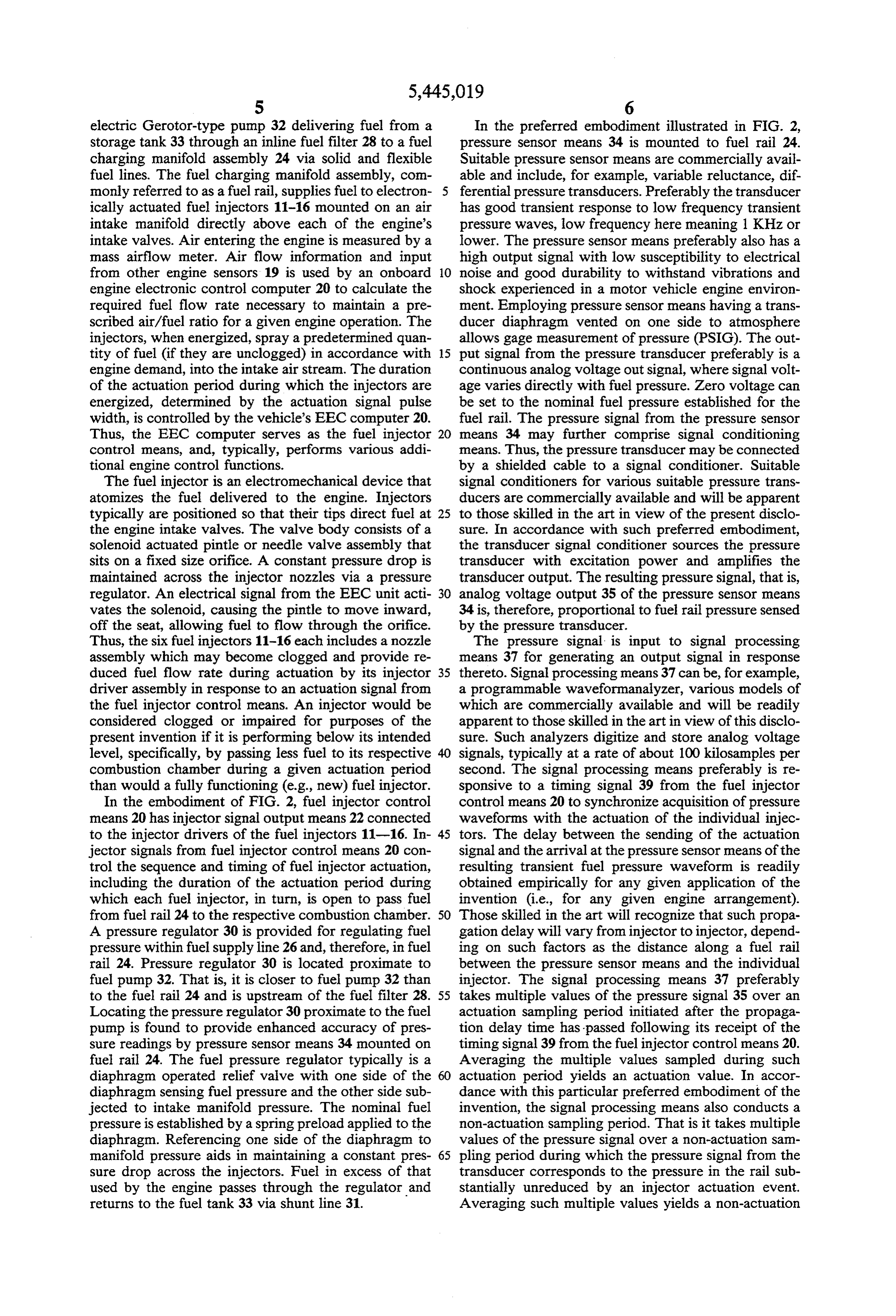
Where: corresponding substantially to actuation of just the in AFV is the value of the adjustment factor for adjust jector in question. In this way, pressure signals for actu ing (by multiplying) the actuation pulse width and, 55 ation of individual injectors can be obtained while the correspondingly, the duration of the actuation per engine is running. The signal processing means then iod for a fuel injector; conducts a sampling period substantially in the manner R is a dimensionless constant equal to the volumetric described above, developing and using the extracted flow rate of the injector (100% unclogged) at the actuation pressure signal for each injector in turn. nominal fuel rail pressure, divided by the pump 60 Referring now to FIG. 3, the output signal of the flow rate also at the nominal fuel rail pressure (both pressure sensor means (in volts) is plotted over time. In of which flow rates are readily measured by rou FIG. 3A the pressure signal is shown for engine opera tine flow stand tests); tion in the aforesaid standard mode wherein all of the dpsin is a dimensionless value which is substantially fuel injectors are actuated in turn in a standard engine constant for a given fuel system and nominal fuel 65 cycle sequence. FIG. 3B shows the pressure signal for rail pressure, being equal to the initial pressure engine operation in the aforesaid test mode wherein drop from the nominal fuel rail pressure immedi actuation of one fuel injector is deleted from an other ately following actuation (allowing for a wave wise standard engine cycle sequence. FIG. 3C shows
Page 10
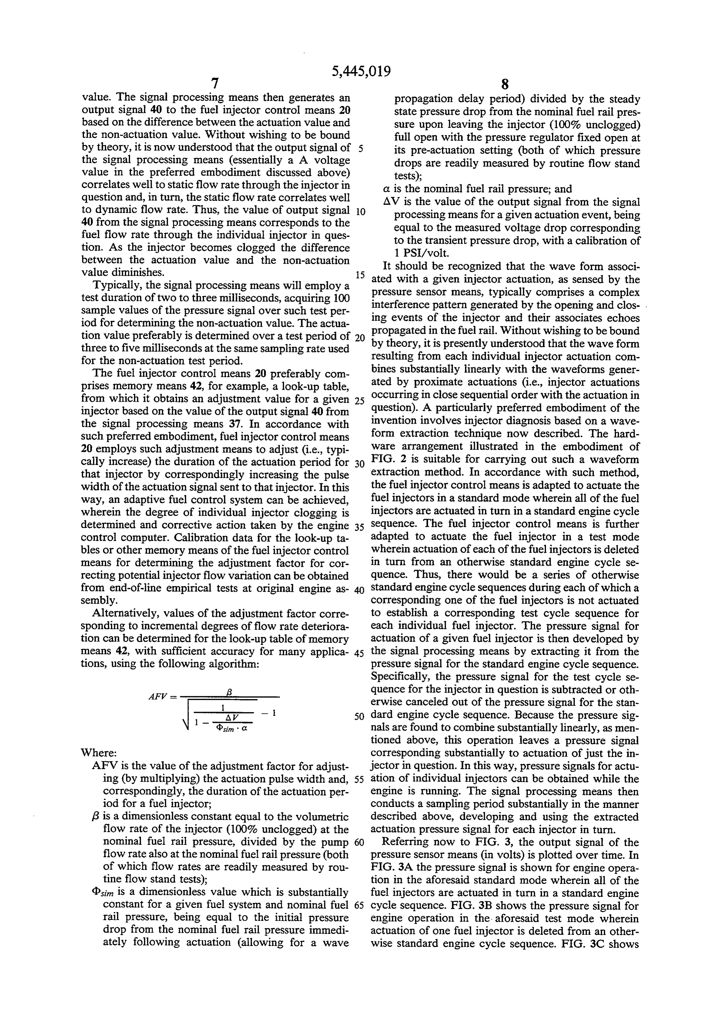
the extracted wave form for the fuel injector deleted fuel return line 127. During testing operation, with first from the test cycle sequence. The wave form of FIG. valve means 150 closed to deadhead the fuel rail and 3C is obtained by the signal processing means by sub second valve means 155 open, pressure is regulated by tracting the wave form of FIG. 3B from that of FIG. pressure regulator 160 in shunt line 131. 3A. As previously described, a timing signal from the Fuel injector diagnosis in the embodiment of FIG. 4 fuel injector control means to the signal processing is carried out substantially in accordance with the vari means initiates a propagation delay period after which ous techniques discussed above. Thus, timing signal 139 the signal sampling occurs based on the extracted wave is sent by fuel injector control means 120 to signal pro form of FIG. 3C. Particularly for motor vehicle appli cessing means 137 to trigger measurement of a propaga cations, it is a highly significant advantage of the extrac 10 tion delay period after which the signal processing tion method of the present invention that the data neces means 137 conducts signal sampling of signal 135 from sary for a complete flow analysis of all fuel injectors can pressure sensor 134. In accordance with certain pre be conducted while the engine is running in substan ferred embodiments, the actuation period sampling is tially normal operation, with virtually no effect percep done in the later (in time) portion of the pressure wave tible by a motor vehicle operator. 15 form trough to reduce complications involved in pro A second preferred embodiment of the invention is cessing the initial higher frequency transients and to schematically illustrated in FIG. 4. The embodiment of more closely estimate the steady-state level of the pres FIG. 4 involves a more traditional fuel injection supply sure drop.
line, in that a fuel return line is provided downstream of As in the case of the embodiment of FIG. 2, the the fuel rail. The system is modified, however, to dead 20 above-described waveform extraction method is pre head the system during fuel injector testing, as now ferred. By averaging multiple values of the pressure described. In addition, the pressure regulator is relo signal taken over the actuation sampling period initiated cated to a location proximate the fuel pump, as in the after the pressure wave propagation delay period, the embodiment of FIG. 2. Suitable regulators are commer signal processing means 137 determines an actuation cially available and will be apparent to those skilled in 25 value corresponding to an individual fuel injector. Av the art in view of the present disclosure. This embodi eraging multiple values of the pressure signal taken over ment permits fuel pressure to be adjusted to preselected a non-actuation sampling period yields a non-actuation production levels, as in the embodiment of FIG. 2. value. The signal processing means sends output signal Locating the regulator remote from the fuel rail can 140 to the fuel injector control means 120 based on the provide individual injector transients in the aggregate 30 difference between the actuation and the non-actuation waveform having more uniform pulse-to-pulse ampli value. In accordance with preferred embodiments, as tudes and signatures. discussed above, fuel injector control means 120 prefer In the embodiment of FIG. 4, fuel pump 132 is ably employs memory means 142, such as a look-up mounted in fuel tank 133 in the customary manner. Fuel table, to determine an adjustment factor for adjusting is supplied during normal engine operation via supply 35 the duration of the actuation period for the fuel injector line 126 which passes through fuel filter 128 to fuel rail in question. Additional inputs 119 may also be fed to 124. Fuel rail 124 feeds fuel to 6 fuel injectors 111 fuel injector control means 120 for determining actua through 116 which are actuated by actuation signals 122 tion duration, for example, inputs from exhaust gas from fuel injector control means 120. As in the embodi sensors, mass airflow sensors, etc. ment of FIG. 2, fuel injector control means 120 prefera Optionally, the system further comprises memory bly is incorporated into an electronic engine control means 143 for storing a value corresponding to an ac module or computer which performs various additional ceptable fuel flow rate through each of the fuel injec engine control functions. tors, and comparitor means for comparing an output Engine 110 in the embodiment of FIG. 4 is adapted signal from the signal processing means to the stored for normal engine operation, during which fuel flow 45 value. The stored value optionally may be the value of provided by the fuel injectors is not necessarily ana an initial output signal from the signal processing means lyzed. Engine 110 also is adapted for fuel injector test for the injector in question. Alternatively, the stored ing operation, during which engine operation continues value may be periodically updated or may be a fixed, while fuel flow provided by the fuel injectors is ana preselected value. An operator signal 165 is generated lyzed. During fuel injector testing operation, the fuel 50 when the comparison of an output signal to its corre supply line is altered by appropriate valving, including sponding stored value indicates an impaired injector. In first valve means 150 in the fuel return line 127 for the case of a motor vehicle engine, such operator signal deadheading the fuel rail during fuel injector testing may cause illumination of an instrument panel warning operation. Specifically, during testing operation valve light or the like. Such operator signal can alert the means 150 closes the fuel return line to fuel flow from 55 operator to seek repair or replacement of the clogged the fuel rail. During normal engine operation valve injector(s) and/or to commence remedial maintenance, means 150 opens the fuel return line 127 to fuel flow such as the use of detergent fuel or the like. from the fuel rail 124. Second valve means 155 is pro Those skilled in the art will recognize that the subject vided in fuel shuntline 131 for closing the fuel shunt line matter disclosed herein can be modified and/or imple during normal engine operation and for opening the fuel mented in alternative embodiments without departing shunt line during fuel injector testing operation. Since from the true scope and spirit of the present invention as trapped vapor can seriously degrade the frequency defined by the following claims.
response of the system, the system preferably is adapted We claim:
to be purged. This occurs normally in the embodiment 1. An internal combustion engine comprising: of FIG. 4 with valve 155 closed and valve 150 open. 65 fuel supply means for supplying liquid fuel under During normal engine operation, with first valve means pressure to combustion cylinders of the engine, 150 open and second valve means 155 closed, pressure comprising at least one fuel injector operatively in the fuel rail is regulated by pressure regulator 130 in connected to a fuel rail;
Page 11
fuel injector control means for individually actuating mounted to the fuel supply line proximate to the said at least one fuel injector to pass fuel from the fuel pump for regulating fuel pressure in the fuel fuel rail during a controlled actuation period; and rail; and an on-board diagnostic system for detecting impaired the fuel injector control means is adapted to actuate fuel injectors during engine operation, said on the fuel injectors, during a fuel injector test period: board diagnostic system comprising: in a standard mode wherein the fuel injectors are pressure sensor means for sensing transient fuel actuated in turn in a standard engine cycle se pressure waves in the fuel rail resulting from quence; and actuation of the fuel injector and for generating in a test mode wherein actuation of each of the fuel pressure signals based thereon corresponding to 10 injectors is deleted in turn from a corresponding fuel quantity passed by the fuel injector during one of a series of otherwise standard engine actuation; and cycle sequences to provide for each fuel injector signal processing means for processing pressure a corresponding test cycle sequence in which it signals from the pressure sensor means and for was not actuated; and generating an output signal in response thereto. 15 the pressure signal for the actuation sampling period 2. The internal combustion engine of claim 1 further of each fuel injector is determined as the difference comprising memory means for storing a value corre between the pressure signal for a standard engine sponding to an acceptable fuel flow rate through said at cycle sequence and the pressure signal for the cor least one fuel injector, and comparator means for com responding test cycle sequence. paring the output signal to the stored value. 20 7. The internal combustion engine of claim 6 wherein 3. The internal combustion engine of claim 1 wherein the pressure signals are generated by the pressure sensor the pressure sensor means comprises a pressure trans means essentially in response to low frequency transient output adapted ducer to generate as the pressure signal an voltage varying with pressure sensed in the fuel fuel pressure waves. rail.
4. An internal combustion engine comprising: 25 fuel supply means for supplying liquid fuel under the8.signal The internal combustion engine of claim 7 wherein pressure to combustion cylinders of the engine, lyzer. processing means comprises a waveform ana comprising at least one fuel injector operatively connected to a fuel rail; 9. The internal combustion engine of claim 6 wherein fuel injector control means for individually actuating 30 the fuel rail is deadheaded.
said at least one fuel injector to pass fuel from the 10. The internal combustion engine of claim 6 fuel rail during a controlled actuation period; and adapted for normal engine operation, during which fuel an on-board diagnostic system for detecting impaired flow provided by the fuel injectors is not analyzed, and fuel injectors during engine operation, said on for fuel injector testing operation, during which engine board diagnostic system comprising: 35 operation continues while fuel flow provided by the pressure sensor means for sensing transient fuel fuel injectors is analyzed, wherein the fuel supply line pressure waves in the fuel rail resulting from comprises a shunt line for returning excess fuel to the actuation of at least one the fuel injector and for fuel tank, bypassing the fuel rail, said pressure regulator generating pressure signals based thereon corre means being mounted in the shunt line for regulating sponding to fuel quantity passed by the fuel in fuel pressure in the fuel rail during the fuel injector jector during attuation; and testing operation and the fuel supply means further signal processing means for processing pressure comprises:
signals from the pressure sensor meads and for a fuel return line for returning fuel from the fuel rail generating an output signal in response thereto, to the fuel tank;
wherein the signal processing means is respon 45 first valve means in the fuel return line for deadhead sive to a timing signal from the fuel injection ing the fuel rail during fuel injector testing opera control means, averaging multiple values of the tion by closing the fuel return line to fuel flow from pressure signal taken during an actuation sam the fuel rail, and for opening the fuel return line to pling period initiated after a predetermined pres fuel flow from the fuel rail during normal engine sure wave propagation delay period following 50 operation;
the timing signal to yield an actuation value, second valve means in the fuel shunt line for closing averaging multiple values of the pressure signal the fuel shunt line during normal engine operation taken during a non-actuation sampling period to and for opening the fuel shunt line during fuel yield a non-actuation value, and generating the injector testing operation; and output signal to the fuel injection control means 55 second pressure regulator means mounted in the fuel based on the difference between the actuation return line for regulating fuel pressure in the fuel value and the non-actuation value. rail during normal engine operation, wherein the 5. The internal combustion engine of claim 4 wherein pressure sensor means is a pressure transducer the fuel injector control means is adapted to adjust the mounted in fluid communication with the fuel rail duration of the actuation period of the fuel injector in 60 for measuring low frequency transient pressure response to the output signal from the signal processing waves in the fuel rail caused by fuel injector actua C2S. tion.
6. The internal combustion engine of claim 4 wherein: 11. A method of detecting impaired fuel injectors in the fuel supply means comprises a plurality of said an internal combustion engine, said internal combustion fuel injectors and further comprises a fuel pump 65 engine comprising:
operatively mounted to a fuel tank, a fuel supply a plurality of said fuel injectors;
line or passing fuel from the fuel pump to the fuel fuel supply means for supplying liquid fuel under rail, and pressure regulator means operatively pressure to the combustion cylinders of the engine,
Page 12
said fuel supply means comprising a plurality of generating a standard pressure signal in response to fuel injectors operatively connected to a fuel rail; the standard engine cycle sequence and a test pres fuel injector control means for individually actuating sure signal for each fuel injector in response to the the fuel injectors to pass fuel from the fuel rail corresponding test cycle sequence; during a controlled actuation period; 5 determining a fuel flow value for each fuel injector, pressure sensor means for sensing transient fuel pres individually, corresponding to fuel quantity passed sure waves in the fuel rail resulting from actuation during its actuation period by comparing the stan of individual fuel injectors and for generating pres dard pressure signal and the test pressure signal to sure signals based thereon corresponding to fuel each other; and quantity passed by the fuel injectors during actua passing the output signal for each fuel injector to the tion; and fuel injector control means and adjusting the actua signal processing means for processing pressure sig tion period of the fuel injector based thereon. nals from the pressure sensor means and for gener step12.ofThe method of claim 11 further comprising the comparing the fuel flow value for each fuel ating an output signal in response thereto; 15 injector, individually, to a stored reference value to said method comprising the steps of: identify which, if any, of the fuel injectors is an in actuating the fuel injectors during a fuel injector test paired fuel injector, and generating an operator signal if period an impaired fuel injector is identified. in a standard mode wherein the fuel injectors are 13. The method of claim 11 wherein the signal pro actuated in turn in a standard engine cycle se cessing means comprises a waveform analyzer and the quence, and in a test mode wherein actuation of output signal to the fuel injector control means for each each of the fuel injectors is deleted in turn from impaired fuel injector indicates its degree of impairment a corresponding one of a series of otherwise and the actuation period of each impaired fuel injector standard engine cycle sequences to provide for is increased an amount corresponding to its degree of each fuel injector a corresponding test cycle 25 impairment.
sequence in which it was not actuated; ck k k sk sk
Provenance
- Collection
- Cited prior art
- Original PDF
- patentimages.storage.googleapis.com →
- Filed
- 1993-04-19
- Pages
- 12
- Method
- pdftotext (the PDF's own text layer) + pdftoppm 300dpi page scans
- Source
- Google Patents bibliographic record
- Granted
- 1995-08-29
- Inventors
- John M. Glidewell; Granger K. Chui; Woong-Chul Yang; Ford Motor Co
- Transcribed from
- patentimages.storage.googleapis.com →