patent · US4419329
Device for producing hydrogen and oxygen gases
6 December 1983
Page 1 — bibliographic record
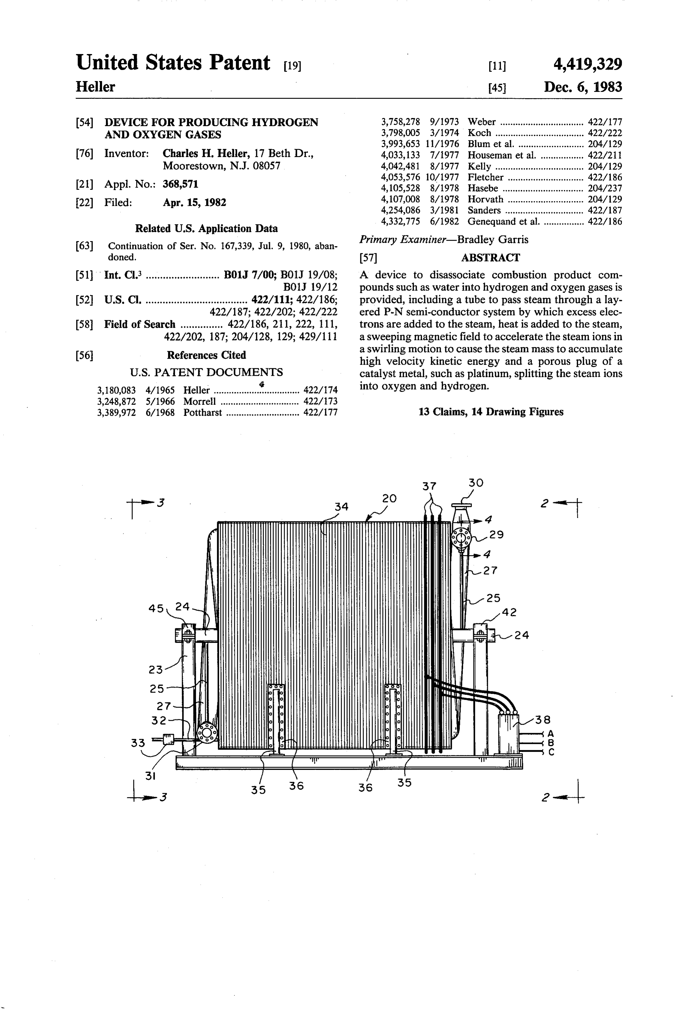
United States Patent (19) 11 4,419,329 Heller 45 Dec. 6, 1983 (54) DEVICE FOR PRODUCING HYDROGEN 3,758,278 9/1973 Weber ................................. 422/177 AND OXYGEN GASES 3,798,005 3/1974 Koch ........ ... 422/222 3,993,653 1 1/1976 Blum et al. ...... ... 204/129 76) Inventor: Charles H. Heller, 17 Beth Dr., 4,033,133 7/1977 Houseman et al ... 422/21 Moorestown, N.J. 08057 4,042,481 8/1977 Kelly ................ ... 204/129 4,053,576 10/1977 Fletcher. ... 422/186 21) Appl. No.: 368,571 4,105,528 8/1978 Hasebe ..... ... 204/237 22) Filed: Apr. 15, 1982 4,107,008 8/1978 Horvath ... ... 204/129 4,254,086 3/1981 Sanders ............ ... 422/187
Related U.S. Application Data
Primary Examiner-Bradley Garris
doned. 57 ABSTRACT (51) Int. Cl. .......................... B01J 7/00; B01J 19/08; A device to disassociate combustion product com BOJ 19/12 pounds such as water into hydrogen and oxygen gases is 52 U.S. C. .................................... 422/111; 422/186; provided, including a tube to pass steam through a lay 422/187; 422/202; 422/222 ered P-N semi-conductor system by which excess elec 58 Field of Search ............... 422/186, 211, 222, 111, trons are added to the steam, heat is added to the steam, 422/202, 187; 204/128, 129; 429/111 a sweeping magnetic field to accelerate the steam ions in 56 References Cited a swirling motion to cause the steam mass to accumulate high velocity kinetic energy and a porous plug of a
3,180,083 4/1965 Heller ................... 422/174 into oxygen and hydrogen.
3,248,872 5/1966 Morrell ............................... 422/173 3,389,972 6/1968 Pottharst ............................. 422/177 13 Claims, 14 Drawing Figures
Page 2
Drawing sheet — no readable text.
Page 3
Drawing sheet — no readable text.
Page 4
Drawing sheet — no readable text.
Page 5
Drawing sheet — no readable text.
Page 6
Drawing sheet — no readable text.
Page 7
Drawing sheet — no readable text.
Page 8
apparatus in a mixture. The methods of separating the
DEVICE FOR PRODUCING HYDROGEN AND hydrogen and oxygen mixture, even though it be an OXYGEN GASES explosive, is well within the prior art.
The inventor, Horvath, in U.S. Pat. No. 4,107,008,
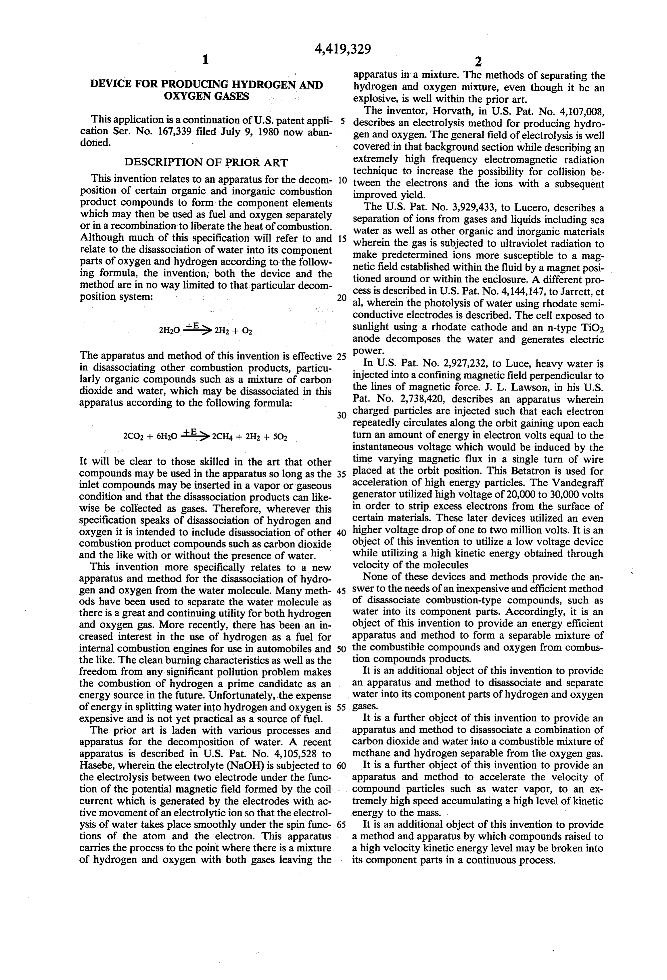
This application is a continuation of U.S. patent appli describes an electrolysis method for producing hydro cation Ser. No. 167,339 filed July 9, 1980 now aban gen and oxygen. The general field of electrolysis is well doned. covered in that background section while describing an DESCRIPTION OF PRIOR ART extremely high frequency electromagnetic radiation technique to increase the possibility for collision be
This invention relates to an apparatus for the decom 10 tween the electrons and the ions with a subsequent position of certain organic and inorganic combustion improved yield.
product compounds to form the component elements The U.S. Pat. No. 3,929,433, to Lucero, describes a which may then be used as fuel and oxygen separately separation of ions from gases and liquids including sea or in a recombination to liberate the heat of combustion. water as well as other organic and inorganic materials Although much of this specification will refer to and 15 wherein the gas is subjected to ultraviolet radiation to relate to the disassociation of water into its component make predetermined parts of oxygen and hydrogen according to the follow netic field established ions more susceptible to a mag within the fluid by a magnet posi ing formula, the invention, both the device and the tioned around or within the enclosure. A different pro method are in no way limited to that particular decom cess is described in U.S. Pat. No. 4,144,147, to Jarrett, et
al, wherein the photolysis of water using rhodate semi conductive electrodes is described. The cell exposed to sunlight using a rhodate cathode and an n-type TiO2 anode decomposes the water and generates electric
The apparatus and method of this invention is effective 25 power.
In U.S. Pat. No. 2,927,232, to Luce, heavy water is in disassociating other combustion products, particu injected into a confining magnetic field perpendicular to larly organic compounds such as a mixture of carbon dioxide and water, which may be disassociated in this the lines of magnetic force. J. L. Lawson, in his U.S. apparatus according to the following formula: Pat. No. 2,738,420, describes an apparatus wherein 30 charged particles are injected such that each electron repeatedly circulates along the orbit gaining upon each turn an amount of energy in electron volts equal to the instantaneous voltage which would be induced by the
It will be clear to those skilled in the art that other time varying magnetic flux in a single turn of wire compounds may be used in the apparatus so long as the 35 placed at the orbit position. This Betatron is used for inlet compounds may be inserted in a vapor or gaseous acceleration of high energy particles. The Vandegraff condition and that the disassociation products can like generator utilized high voltage of 20,000 to 30,000 volts wise be collected as gases. Therefore, wherever this certain in order to strip excess electrons from the surface of specification speaks of disassociation of hydrogen and materials. These later devices utilized an even oxygen it is intended to include disassociation of other 40 higher voltage drop of one to two million volts. It is an combustion product compounds such as carbon dioxide object of this invention to utilize a low voltage device and the like with or without the presence of water. while utilizing a high kinetic energy obtained through This invention more specifically relates to a new velocity of the molecules apparatus and method for the disassociation of hydro None of these devices and methods provide the an gen and oxygen from the water molecule. Many meth 45 swer to the needs of an inexpensive and efficient method ods have been used to separate the water molecule as of disassociate combustion-type compounds, such as there is a great and continuing utility for both hydrogen water into its component parts. Accordingly, it is an and oxygen gas. More recently, there has been an in object of this invention to provide an energy efficient creased interest in the use of hydrogen as a fuel for apparatus and method to form a separable mixture of internal combustion engines for use in automobiles and 50 the combustible compounds and oxygen from combus the like. The clean burning characteristics as well as the tion compounds products.
freedom from any significant pollution problem makes It is an additional object of this invention to provide the combustion of hydrogen a prime candidate as an an apparatus and method to disassociate and separate energy source in the future. Unfortunately, the expense water into its component parts of hydrogen and oxygen of energy in splitting water into hydrogen and oxygen is 55 gases.
expensive and is not yet practical as a source of fuel. It is a further object of this invention to provide an The prior art is laden with various processes and . apparatus and method to disassociate a combination of apparatus for the decomposition of water. A recent carbon dioxide and water into a combustible mixture of apparatus is described in U.S. Pat. No. 4,105,528 to methane and hydrogen separable from the oxygen gas. Hasebe, wherein the electrolyte (NaOH) is subjected to 60 It is a further object of this invention to provide an the electrolysis between two electrode under the func apparatus and method to accelerate the velocity of tion of the potential magnetic field formed by the coil. compound particles such as water vapor, to an ex current which is generated by the electrodes with ac tremely high speed accumulating a high level of kinetic tive movement of an electrolytic ion so that the electrol energy to the mass.
ysis of water takes place smoothly under the spin func 65 It is an additional object of this invention to provide tions of the atom and the electron. This apparatus a method and apparatus by which compounds raised to carries the process to the point where there is a mixture a high velocity kinetic energy level may be broken into of hydrogen and oxygen with both gases leaving the its component parts in a continuous process.
Page 9
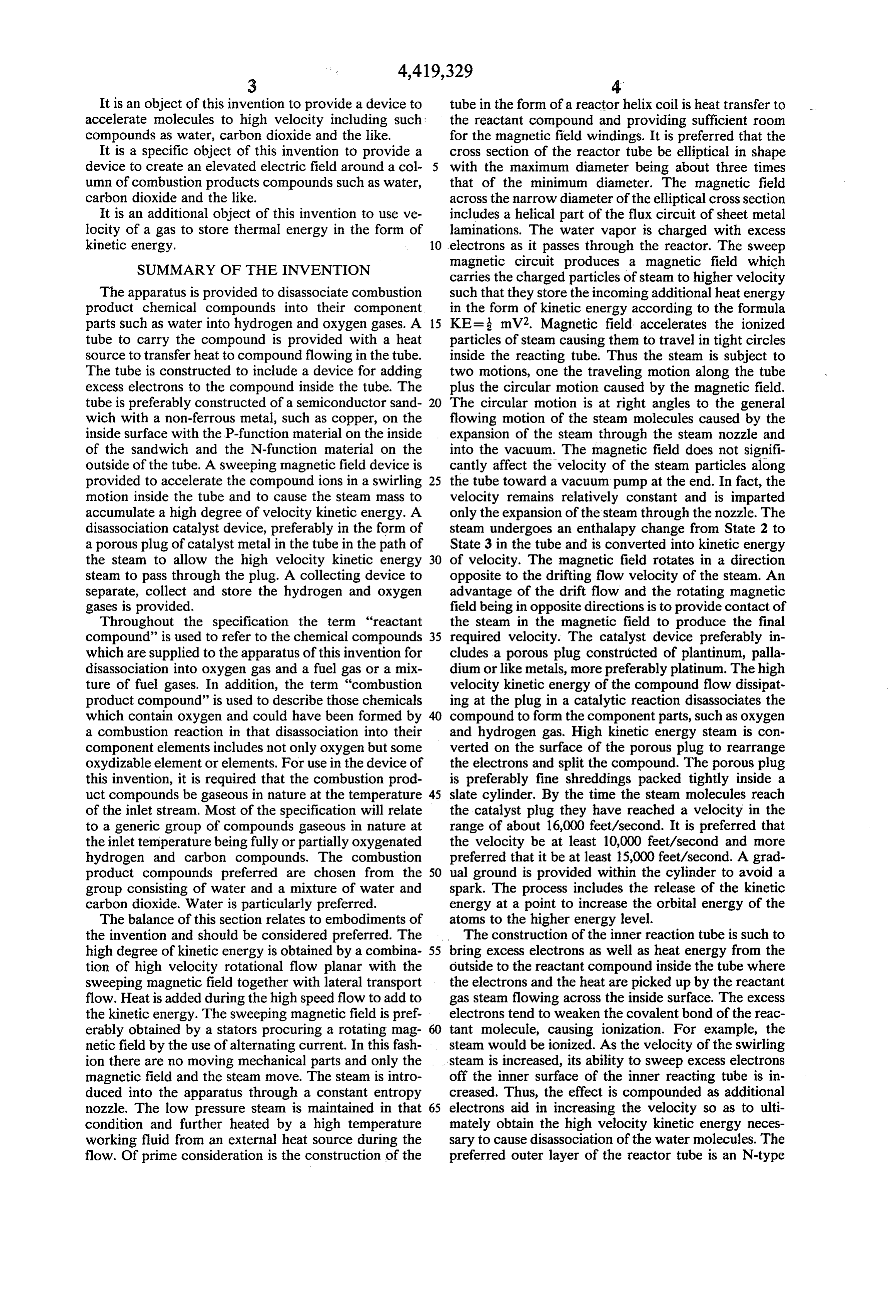
It is an object of this invention to provide a device to tube in the form of a reactor helix coil is heat transfer to accelerate molecules to high velocity including such the reactant compound and providing sufficient room compounds as water, carbon dioxide and the like. for the magnetic field windings. It is preferred that the It is a specific object of this invention to provide a cross section of the reactor tube be elliptical in shape device to create an elevated electric field around a col 5 with the maximum diameter being about three times umn of combustion products compounds such as water, that of the minimum diameter. The magnetic field carbon dioxide and the like. across the narrow diameter of the elliptical cross section It is an additional object of this invention to use ve includes a helical part of the flux circuit of sheet metal locity of a gas to store thermal energy in the form of laminations. The water vapor is charged with excess kinetic energy. 10 electrons as it passes through the reactor. The sweep SUMMARY OF THE INVENTION magnetic circuit produces a magnetic field which carries the charged particles of steam to higher velocity
The apparatus is provided to disassociate combustion such that they store the incoming additional heat energy product chemical compounds into their component in the form of kinetic energy according to the formula parts such as water into hydrogen and oxygen gases. A 15 KE= mV2. Magnetic field accelerates the ionized tube to carry the compound is provided with a heat particles of steam causing them to travel in tight circles source to transfer heat to compound flowing in the tube. inside the reacting tube. Thus the steam is subject to The tube is constructed to include a device for adding two motions, one the traveling motion along the tube excess electrons to the compound inside the tube. The plus the circular motion caused by the magnetic field. tube is preferably constructed of a semiconductor sand 20 The circular motion is at right angles to the general wich with a non-ferrous metal, such as copper, on the flowing motion of the steam molecules caused by the inside surface with the P-function material on the inside expansion of the steam through the steam nozzle and of the sandwich and the N-function material on the into the vacuum. The magnetic field does not signifi outside of the tube. A sweeping magnetic field device is cantly affect the velocity of the steam particles along provided to accelerate the compound ions in a swirling 25 the tube toward a vacuum pump at the end. In fact, the motion inside the tube and to cause the steam mass to velocity remains relatively constant and is imparted accumulate a high degree of velocity kinetic energy. A only the expansion of the steam through the nozzle. The disassociation catalyst device, preferably in the form of steam undergoes an enthalapy change from State 2 to a porous plug of catalyst metal in the tube in the path of State 3 in the tube and is converted into kinetic energy the steam to allow the high velocity kinetic energy 30 of velocity. The magnetic field rotates in a direction steam to pass through the plug. A collecting device to opposite to the drifting flow velocity of the steam. An separate, collect and store the hydrogen and oxygen advantage of the drift flow and the rotating magnetic gases is provided. field being in opposite directions is to provide contact of Throughout the specification the term "reactant the steam in the magnetic field to produce the final compound' is used to refer to the chemical compounds 35 required velocity. The catalyst device preferably in which are supplied to the apparatus of this invention for cludes a porous plug constructed of plantinum, palla disassociation into oxygen gas and a fuel gas or a mix dium or like metals, more preferably platinum. The high ture of fuel gases. In addition, the term “combustion velocity kinetic energy of the compound flow dissipat product compound' is used to describe those chemicals ing at the plug in a catalytic reaction disassociates the which contain oxygen and could have been formed by compound to form the component parts, such as oxygen a combustion reaction in that disassociation into their and hydrogen gas. High kinetic energy steam is con component elements includes not only oxygen but some verted on the surface of the porous plug to rearrange oxydizable element or elements. For use in the device of the electrons and split the compound. The porous plug this invention, it is required that the combustion prod is preferably fine shreddings packed tightly inside a uct compounds be gaseous in nature at the temperature 45 slate cylinder. By the time the steam molecules reach of the inlet stream. Most of the specification will relate the catalyst plug they have reached a velocity in the to a generic group of compounds gaseous in nature at range of about 16,000 feet/second. It is preferred that the inlet temperature being fully or partially oxygenated the velocity be at least 10,000 feet/second and more hydrogen and carbon compounds. The combustion preferred that it be at least 15,000 feet/second. A grad product compounds preferred are chosen from the 50 ual ground is provided within the cylinder to avoid a group consisting of water and a mixture of water and spark. The process includes the release of the kinetic carbon dioxide. Water is particularly preferred. energy at a point to increase the orbital energy of the The balance of this section relates to embodiments of atoms to the higher energy level. the invention and should be considered preferred. The The construction of the inner reaction tube is such to high degree of kinetic energy is obtained by a combina 55 bring excess electrons as well as heat energy from the tion of high velocity rotational flow planar with the outside to the reactant compound inside the tube where sweeping magnetic field together with lateral transport the electrons and the heat are picked up by the reactant flow. Heat is added during the high speed flow to add to gas steam flowing across the inside surface. The excess the kinetic energy. The sweeping magnetic field is pref electrons tend to weaken the covalent bond of the reac erably obtained by a stators procuring a rotating mag 60 tant molecule, causing ionization. For example, the netic field by the use of alternating current. In this fash steam would be ionized. As the velocity of the swirling ion there are no moving mechanical parts and only the steam is increased, its ability to sweep excess electrons magnetic field and the steam move. The steam is intro off the inner surface of the inner reacting tube is in duced into the apparatus through a constant entropy creased. Thus, the effect is compounded as additional nozzle. The low pressure steam is maintained in that 65 electrons aid in increasing the velocity so as to ulti condition and further heated by a high temperature mately obtain the high velocity kinetic energy neces working fluid from an external heat source during the sary to cause disassociation of the water molecules. The flow. Of prime consideration is the construction of the preferred outer layer of the reactor tube is an N-type
Page 10
material such as silicon ribbon semiconductor material. flooring all securely fastened to a twelve inch thick The inside layer is copper sandwiching the interior concrete floor. Front end pedestal support 22 and rear layer which is the P-type silicon material. The construc end pedestal support 23 are both bolted and pinned to tion is such that once electrons cross the P-N junction foundation 21 "I'beam. Pedestal supports 22 and 23 are they are trapped inside the tube and carried off by the constructed of inch steel welded to form square cross steam stream. In this construction, it is important that section beam extending a height to hold twelve inch the P-N junction be able to withstand a potential of diameter schedule 80 steel pipe main helix support 24. about 15 volts as the device acts as a diode. The external
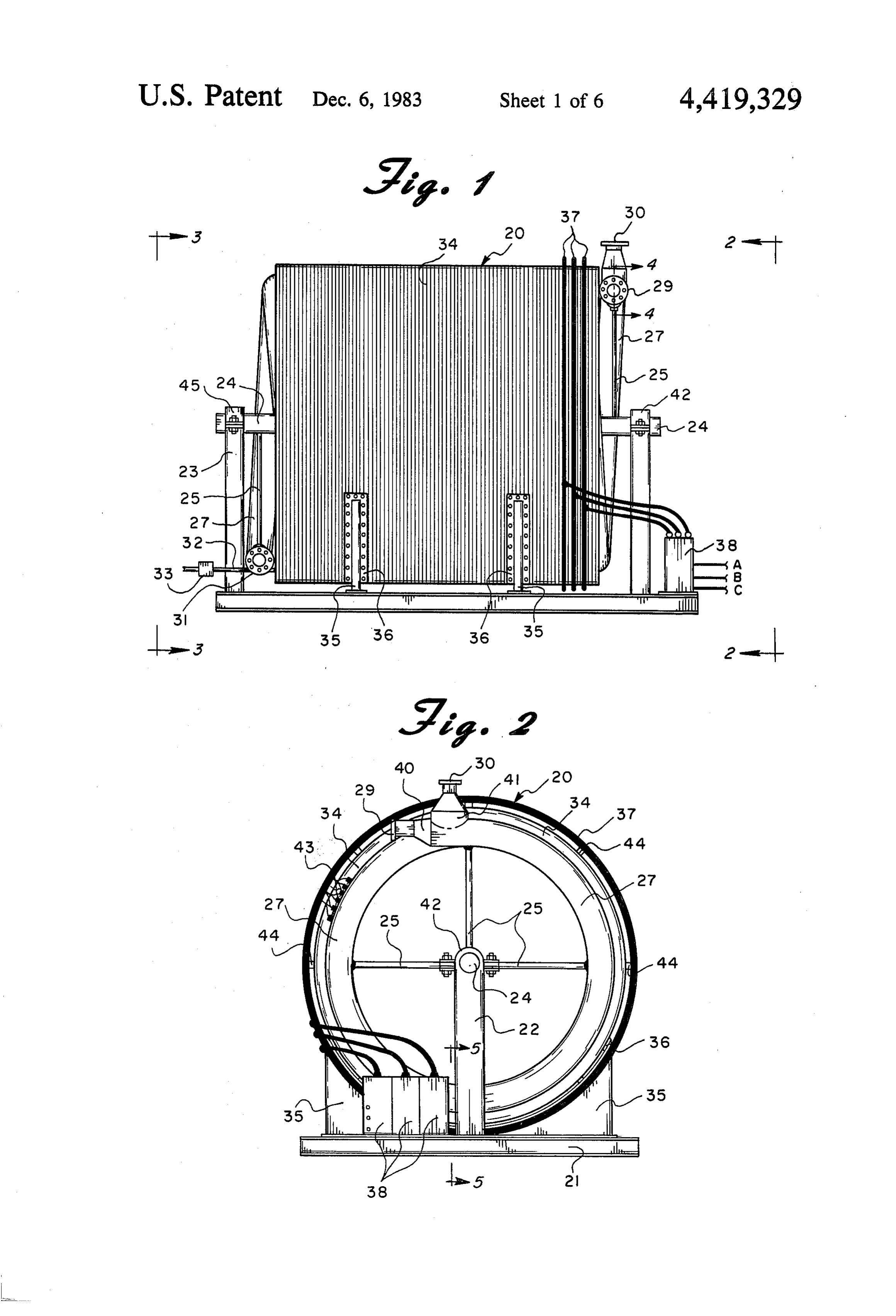
Extending radially from and welded into main helix magnetic circuit encloses the helix reactant tube to support 24 are helix support rods 25 which are con provide an alternating flux. 10 structed of one and inch diameter steel pipe welded Inside the inner reactant tube excess electrons are shut before being welded at one end to main helix sup added to the steam causing the steam to ionize creating port 24 and securely fastened with plate and screws at an electric field of voltage above ground in the steam. the other end to the inner magnetic circuit in helix tube The sweeping magnetic field created between an inner 27. Helix support rods 25 are located one for each 90 of stator circuit and outer circuit windings accelerates the 15 turn of helix tube 27. Steam inlet port 29 is a ten inch steam ions. This acceleration causes the mass of steam steel pipeline to supply 28 psig steam for separation into to store heat energy and magnetic energy from the hydrogen fuel and oxygen. As pointed out hereinabove, rotating magnetic field in kinetic energy of the steam fuel producer 20 is capable of breaking not only steam molecules. When an equivalent energy to 13.5 electrons into hydrogen and oxygen gases but also a mixture of volts is reached steam may be converted to hydrogen 20 carbon dioxide and steam into a mixture of methane, and oxygen. In the second state of the reaction, the hydrogen and oxygen which can also be easily sepa steam of high velocity kinetic energy is passed through rated into a fuel mixture. If the latter fuel mixture is a porous plug of catalyst metal, preferably platinum or desired, a mixture of three moles steam and one mole paladium and more preferably platinum. The steam in carbon dioxide enters at inlet 29. For simplicity the passing through the plug gives up kinetic energy and 25 present description will relate to a run using steam sup that goes to push the electrons of each steam atom fur plied to inlet 29 from a source not shown. Heating fluid ther apart leaving room for rearrangement of the elec inlet 30 is a six inch diameter Schedule 40 steel pipe for trons of the steam to form hydrogen and oxygen. The 5 psig steam which is typically supplied from a solar kinetic energy accumulated in the molecules is stored in collector or other heat source. Oxygen and hydrogen a stable form of the hydrogen and oxygen molecules. 30 gases leave fuel producer 20 from exit port 31 and con BRIEF DESCRIPTION OF THE DRAWINGS denser drain tube 32 is connected to the hearing jacket into which steam enters from inlet 30 to remove con
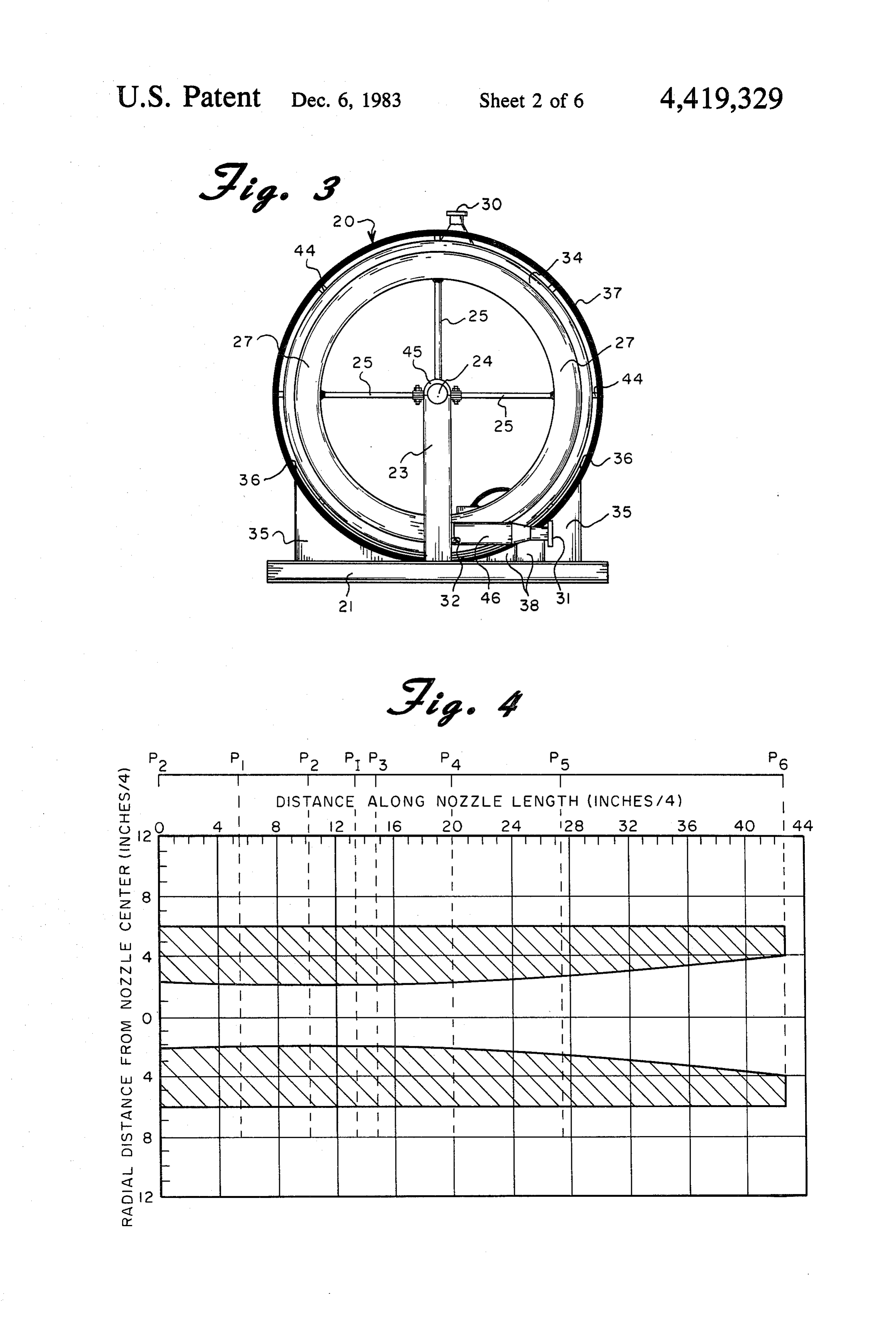
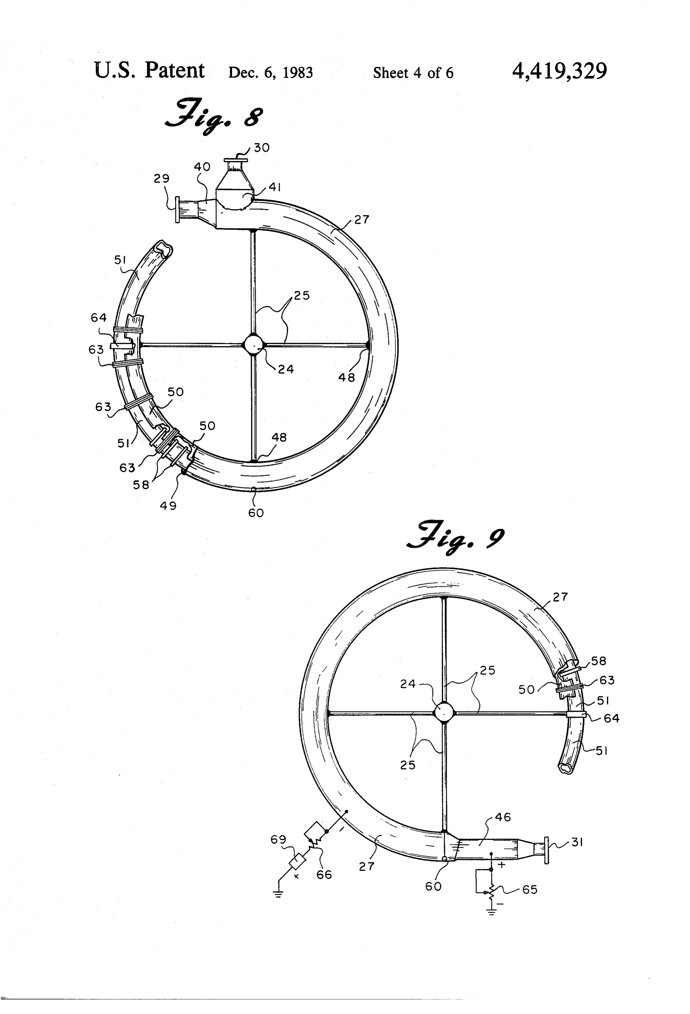
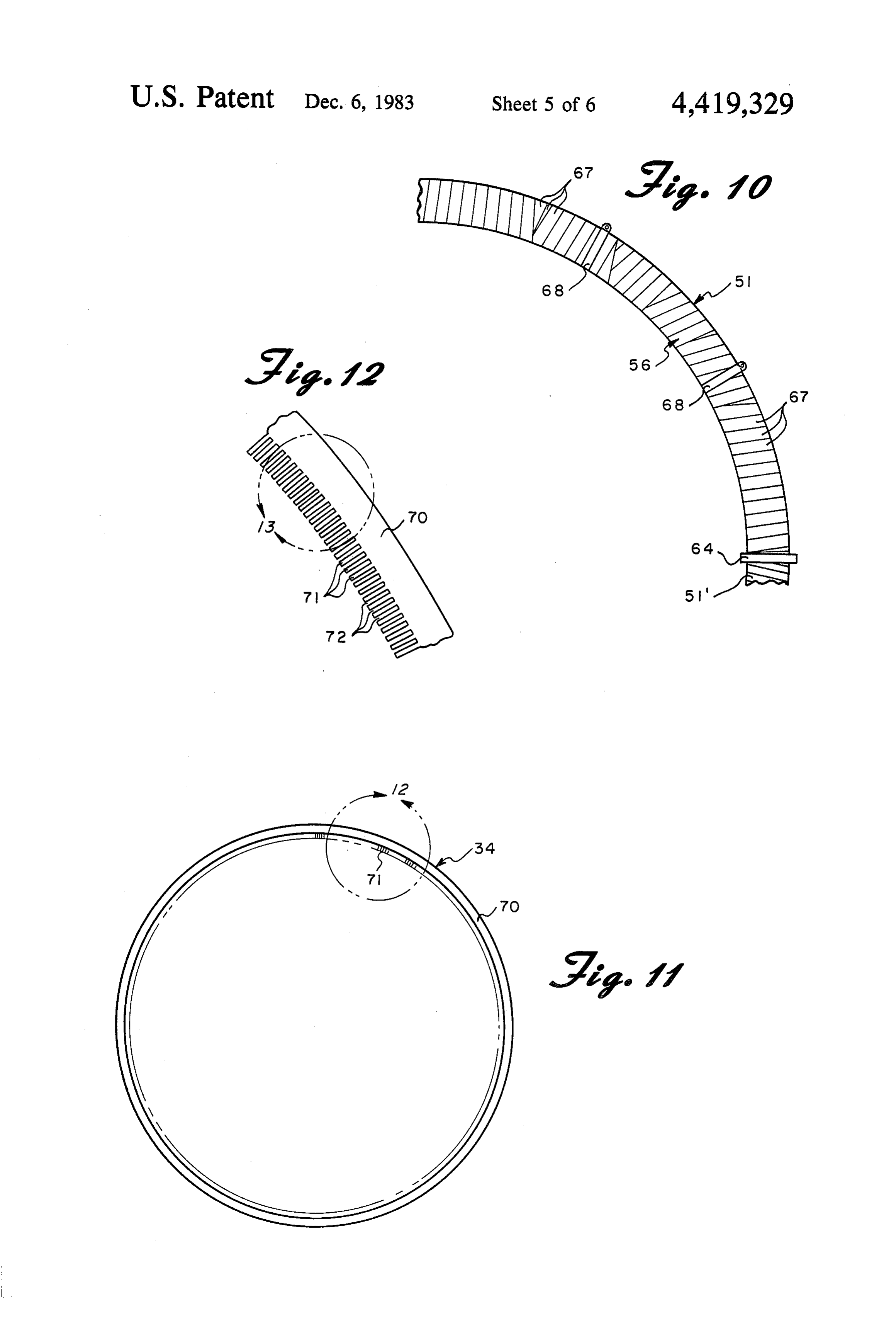
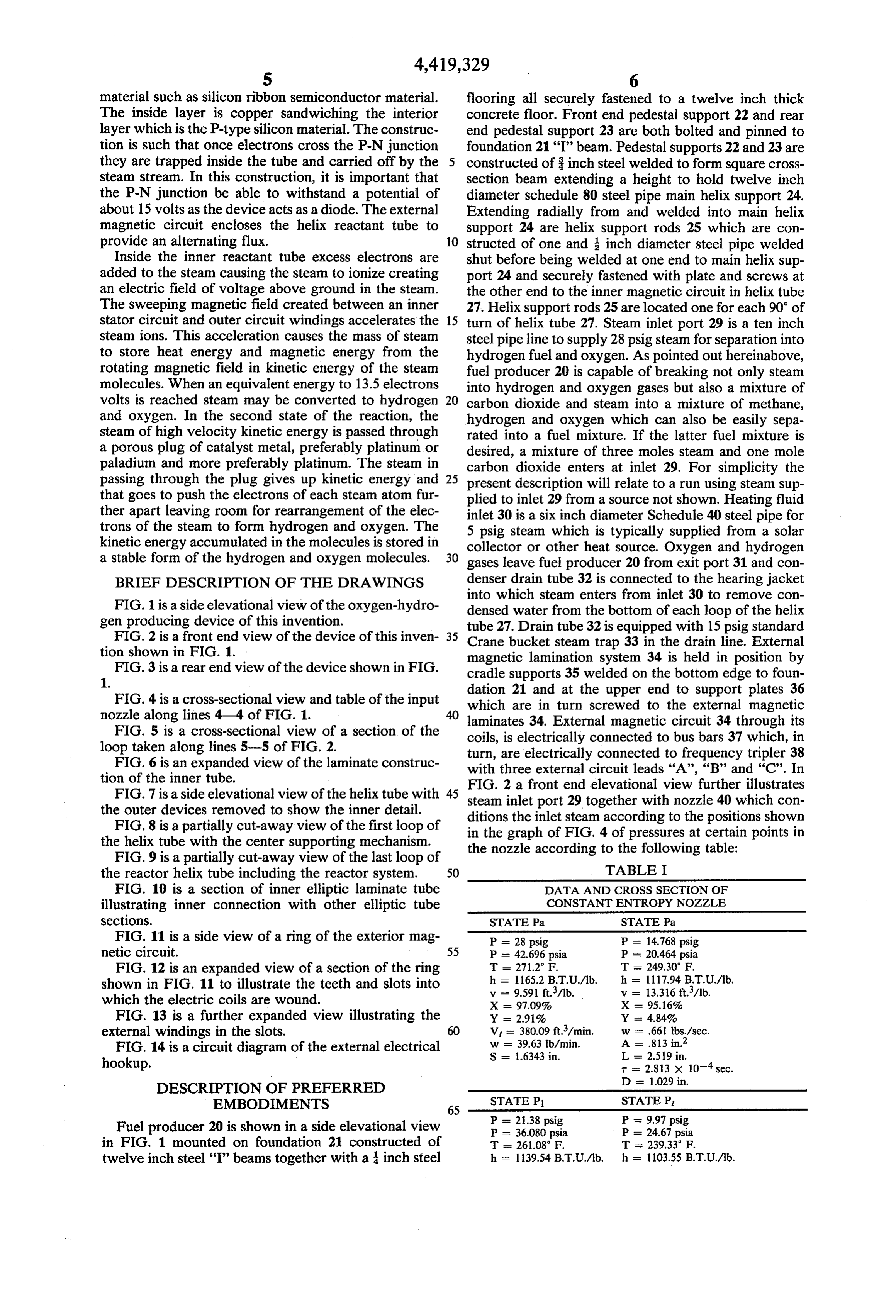
FIG. 1 is a side elevational view of the oxygen-hydro densed water from the bottom of each loop of the helix gen producing device of this invention. tube 27. Drain tube 32 is equipped with 15 psig standard FIG. 2 is a front end view of the device of this inven 35 Crane bucket steam trap 33 in the drain line. External tion shown in FIG. 1. magnetic lamination system 34 is held in position by FIG. 3 is a rear end view of the device shown in FIG. cradle supports 35 welded on the bottom edge to foun 1. dation 21 and at the upper end to support plates 36 FIG. 4 is a cross-sectional view and table of the input which are in turn screwed to the external magnetic nozzle along lines 4-4 of FIG. 1. laminates 34. External magnetic circuit 34 through its FIG. 5 is a cross-sectional view of a section of the coils, is electrically connected to bus bars 37 which, in loop taken along lines 5-5 of FIG. 2. turn, are electrically connected to frequency tripler 38 FIG. 6 is an expanded view of the laminate construc with three external circuit leads 'A', 'B' and 'C'. In tion of the inner tube. FIG. 2 a front end elevational view further illustrates FIG. 7 is a side elevational view of the helix tube with 45 the outer devices removed to show the inner detail. steam inlet port 29 together with nozzle 40 which con FIG. 8 is a partially cut-away view of the first loop of ditions the inlet steam according to the positions shown the helix tube with the center supporting mechanism. in the graph of FIG. 4 of pressures at certain points in FIG. 9 is a partially cut-away view of the last loop of the nozzle according to the following table: the reactor helix tube including the reactor system. 50 TABLE I FIG. 10 is a section of inner elliptic laminate tube DATA AND CROSS SECTION OF illustrating inner connection with other elliptic tube CONSTANT ENTROPY NOZZLE sections. STATE Pa STATE Pa FIG. 11 is a side view of a ring of the exterior mag P = 28 psig P = 14.768 psig netic circuit. 55 P = 42.696 psia P = 20.464 psia FIG. 12 is an expanded view of a section of the ring T - 271.2 F.
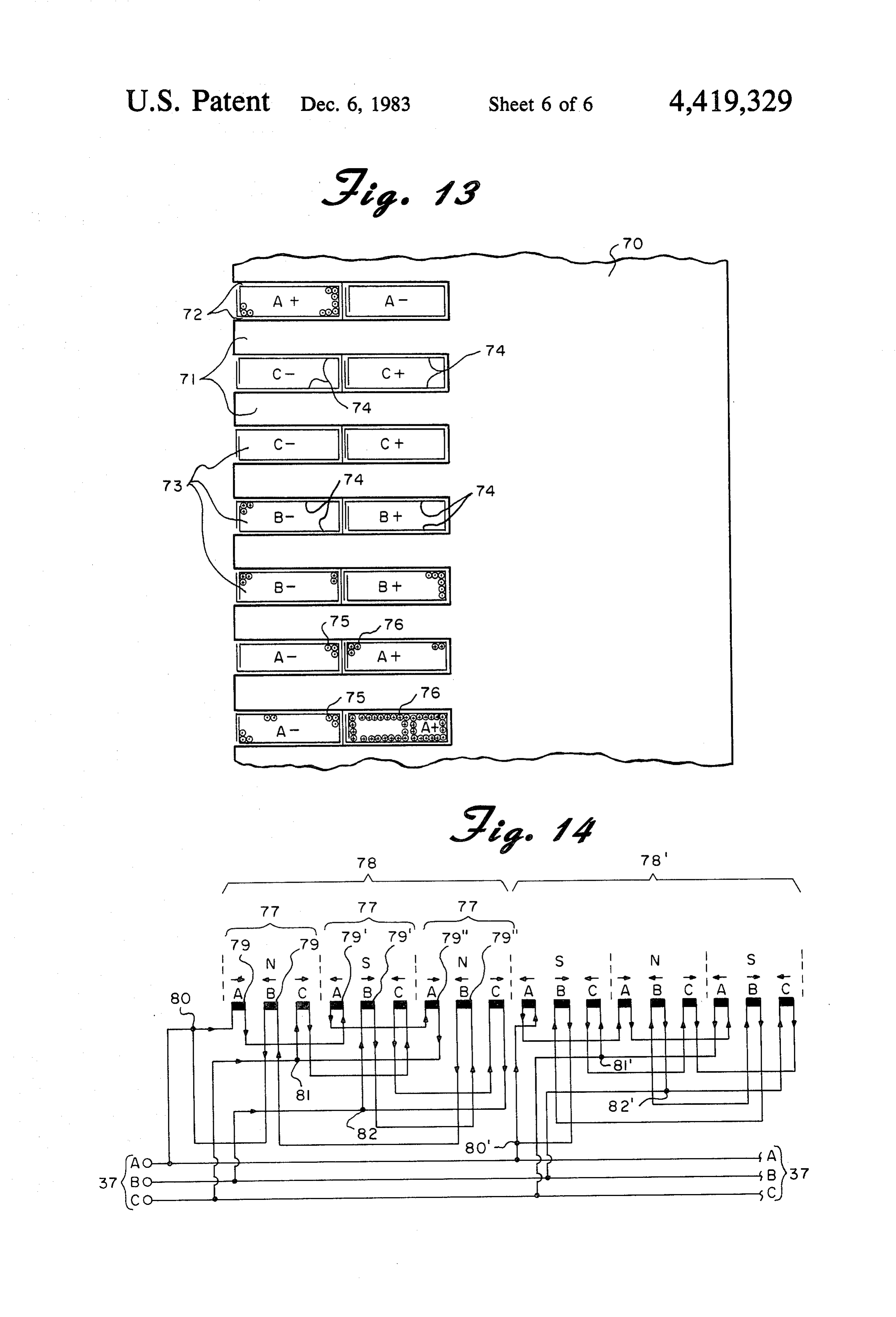
shown in FIG. 11 to illustrate the teeth and slots into v - 9.591 ft./1b. w = 13.316 ft./1b. which the electric coils are wound. X = 97.09% X = 95.16% FIG. 13 is a further expanded view illustrating the Y 2.91% Y is 4.84% external windings in the slots. 60 V = 380.09 ft./min.
FIG. 14 is a circuit diagram of the external electrical S = 1.6343 in. L = 2.519 in. hookup. T = 2.813 x 10 sec.
DESCRIPTION OF PREFERRED
EMBODIMENTS STATE P1 STATE P.
Fuel producer 20 is shown in a side elevational view P = 36.080 psia P = 24.67 psia in FIG. 1 mounted on foundation 21 constructed of T 261.08 F T - 239.33 F. twelve inch steel "I' beams together with a inch steel h 13954 BTU/lb. h = 103.5s BTU/lb.
Page 11
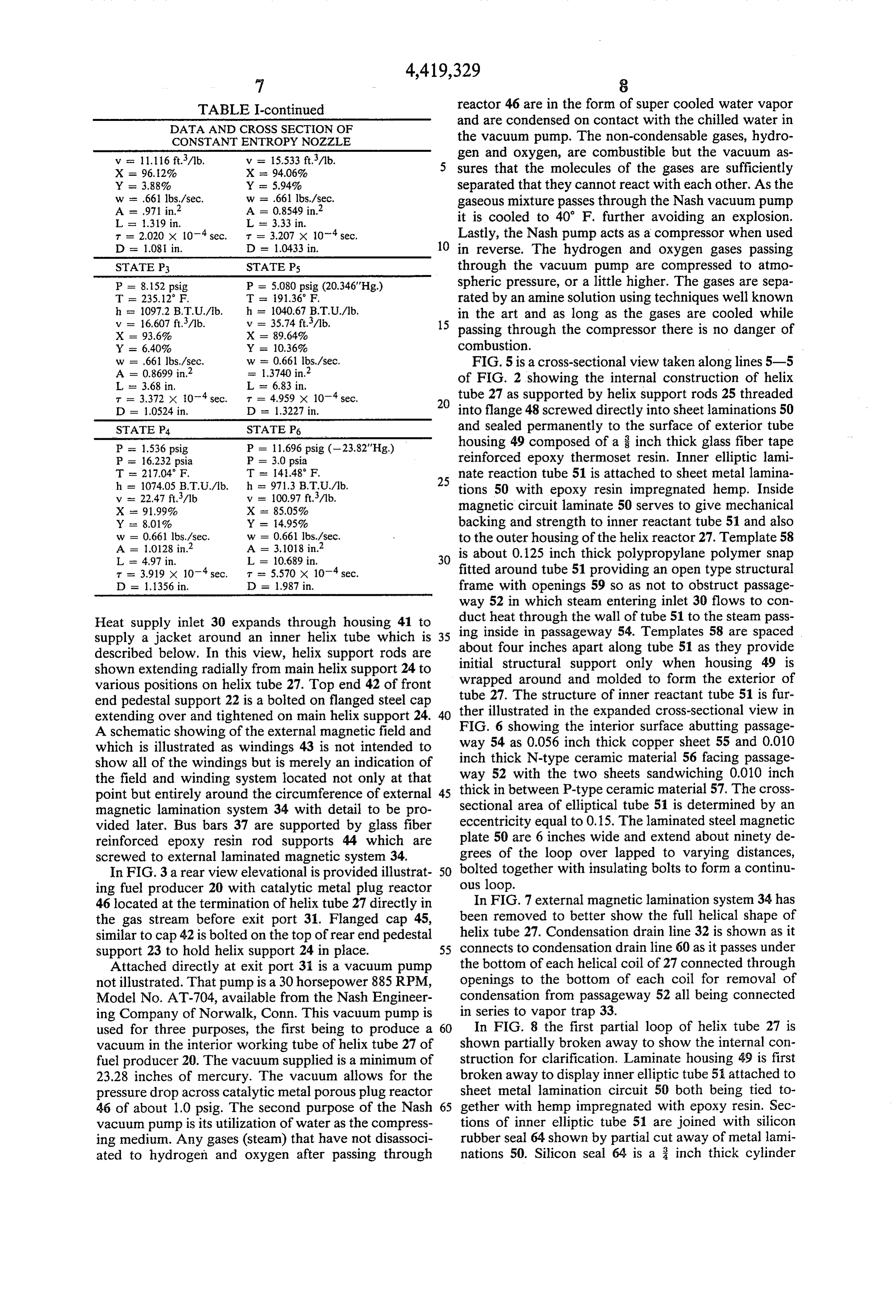
TABLE I-continued reactor 46 are in the form of super cooled water vapor
DATA AND CROSS SECTION OF
and are condensed on contact with the chilled water in
CONSTANT ENTROPY NOZZLE the vacuum pump. The non-condensable gases, hydro v = 11.116 ft./1b. v = 15.533 ft./1b. gen and oxygen, are combustible but the vacuum as X = 96.12% X is 94.06% sures that the molecules of the gases are sufficiently Y = 3.88% Y = 5.94% separated that they cannot react with each other. As the
A = 0.8549 in.2 gaseous mixture passes through the Nash vacuum pump
L = .319 in. L = 3.33 in. it is cooled to 40' F. further avoiding an explosion. T = 2,020 x 10' sec. r = 3.207 x 10-sec. Lastly, the Nash pump acts as a compressor when used D = 1.08 in. D = 1.0433 in. 10 in reverse. The hydrogen and oxygen gases passing STATE P3 STATE Ps through the vacuum pump are compressed to atmo P = 8.152 psig P = 5.080 psig (20.346"Hg) spheric pressure, or a little higher. The gases are sepa T 23.5.12 F. T 91.36 F. rated by an amine solution using techniques well known h = 1097.2 B.T.U./b. h as 1040.67 B.T.U.A.b. in the art and as long as the gases are cooled while v = 16,607 ft./1b. v = 35.74 ft./1b. 15 passing through the compressor there is no danger of
Y = 6.40% Y = 10.36% combustion.
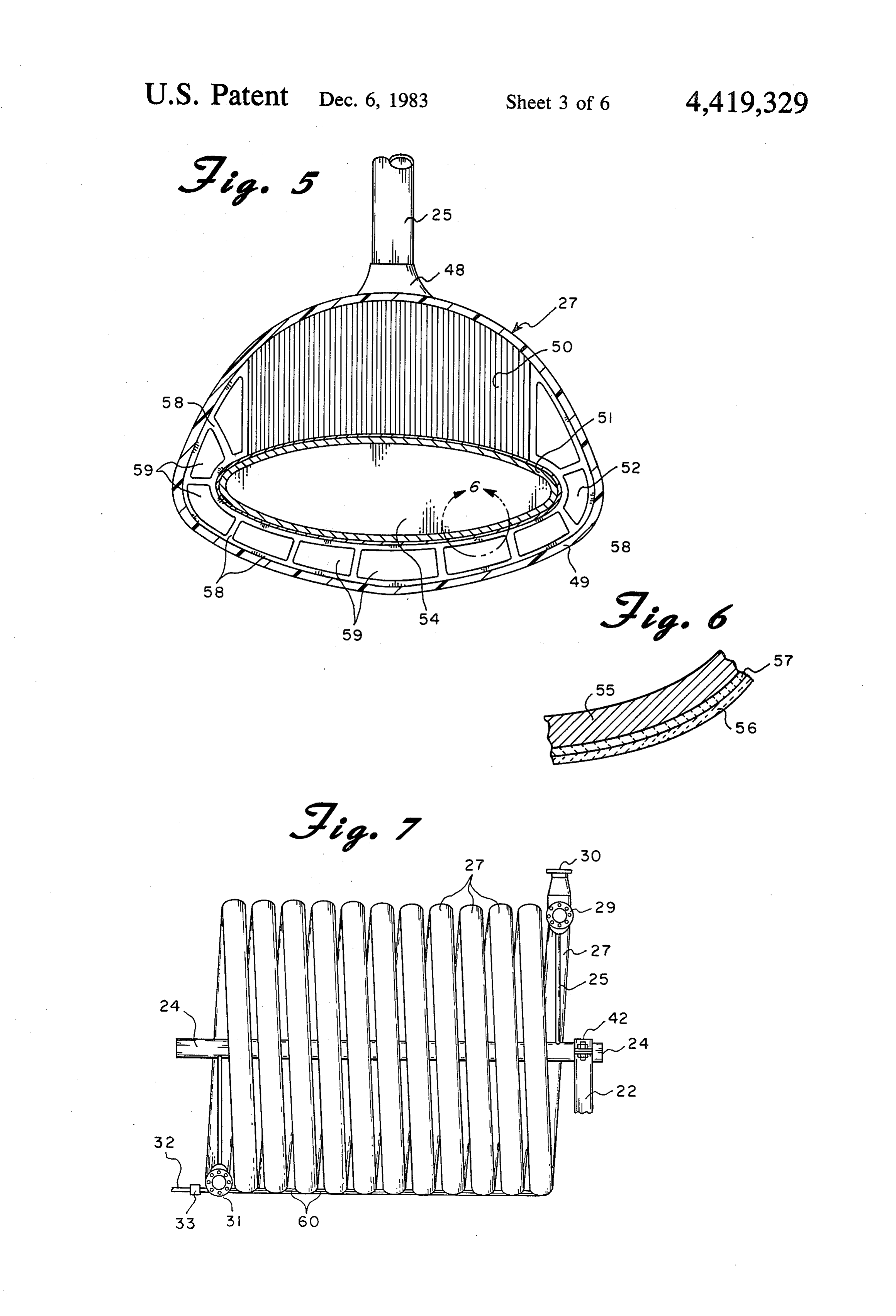
= 1.3740 in.2 FIG. 5 is a cross-sectional view taken along lines 5-5 L = 3.68 in. L = 6.83 in. of FIG. 2 showing the internal construction of helix
tube 27 as supported by helix support rods 25 threaded
D = 1.0524 in. D = 1.3227 in. into flange 48 screwed directly into sheet laminations 50 STATE P4 STATE P6 - and sealed permanently to the surface of exterior tube P = 1.536 psig P = 11.696 psig (-23.82"Hg) housing 49 composed of a inch thick glass fiber tape P = 16.232 psia P = 3.0 psia reinforced epoxy thermoset resin. Inner elliptic lami
nate reaction tube 51 is attached to sheet metal lamina h = 1074.05 B.T.U./lb. h = 971.3 B.T.U./b. tions 50 with epoxy resin impregnated hemp. Inside
X - 91.99% X - 85.05% magnetic circuit laminate 50 serves to give mechanical Y - 8.01% Y = 4.95% backing and strength to inner reactant tube 51 and also
to the outer housing of the helix reactor 27. Template 58
L = 4,97 in. L = 10.689 in, 30 is about 0.125 inch thick polypropylane polymer snap t = 3.919 x 10 sec. T = 5.570 x 10 sec. fitted around tube 51 providing an open type structural D = 1.356 in. D = 1.987 in. frame with openings 59 so as not to obstruct passage way 52 in which steam entering inlet 30 flows to con
Heat supply inlet 30 expands through housing 41 to duct heat through the wall of tube 51 to the steam pass supply a jacket around an inner helix tube which is about fourininches 35 ing inside passageway 54. Templates 58 are spaced apart along tube 51 as they provide described below. In this view, helix support rods are shown extending radially from main helix support 24 to initial structural support only when housing 49 is wrapped around and molded to form the exterior of various positions on helix tube 27. Top end 42 of front tube 27. The structure of inner reactant tube 51 is fur end pedestal support 22 is a bolted on flanged steel cap extending over and tightened on main helix support 24. FIG. 6 showinginthe 40 ther illustrated the expanded cross-sectional view in interior surface abutting passage
A schematic showing of the external magnetic field and which is illustrated as windings 43 is not intended to way 54 as 0.056 inch thick copper sheet 55 and 0.010 show all of the windings but is merely an indication of inch thick N-type ceramic material 56 facing passage the field and winding system located not only at that way 52 with the two sheets sandwiching 0.010 inch point but entirely around the circumference of external 45 thick in between P-type ceramic material 57. The cross magnetic lamination system 34 with detail to be pro sectional area of elliptical tube 51 is determined by an vided later. Bus bars 37 are supported by glass fiber eccentricity equal to 0.15. The laminated steel magnetic reinforced epoxy resin rod supports 44 which are plate 50 are 6 inches wide and extend about ninety de screwed to external laminated magnetic system 34. grees of the loop over lapped to varying distances, In FIG.3 a rear view elevational is provided illustrat 50 bolted together with insulating bolts to form a continu ing fuel producer 20 with catalytic metal plug reactor ous loop.
46 located at the termination of helix tube 27 directly in In FIG. 7 external magnetic lamination system 34 has the gas stream before exit port 31. Flanged cap 45, been removed to better show the full helical shape of similar to cap 42 is bolted on the top of rear end pedestal helix tube 27. Condensation drain line 32 is shown as it support 23 to hold helix support 24 in place. 55 connects to condensation drain line 60 as it passes under Attached directly at exit port 31 is a vacuum pump the bottom of each helical coil of 27 connected through not illustrated. That pump is a 30 horsepower 885 RPM, openings to the bottom of each coil for removal of Model No. AT-704, available from the Nash Engineer condensation from passageway 52 all being connected ing Company of Norwalk, Conn. This vacuum pump is in series to vapor trap 33.
used for three purposes, the first being to produce a 60 In FIG. 8 the first partial loop of helix tube 27 is vacuum in the interior working tube of helix tube 27 of shown partially broken away to show the internal con fuel producer 20. The vacuum supplied is a minimum of struction for clarification. Laminate housing 49 is first 23.28 inches of mercury. The vacuum allows for the broken away to display inner elliptic tube 51 attached to pressure drop across catalytic metal porous plug reactor sheet metal lamination circuit 50 both being tied to 46 of about 1.0 psig. The second purpose of the Nash 65 gether with hemp impregnated with epoxy resin. Sec vacuum pump is its utilization of water as the compress tions of inner elliptic tube 51 are joined with silicon ing medium. Any gases (steam) that have not disassoci rubber seal 64 shown by partial cut away of metal lami ated to hydrogen and oxygen after passing through nations 50. Silicon seal 64 is a 3 inch thick cylinder
Page 12
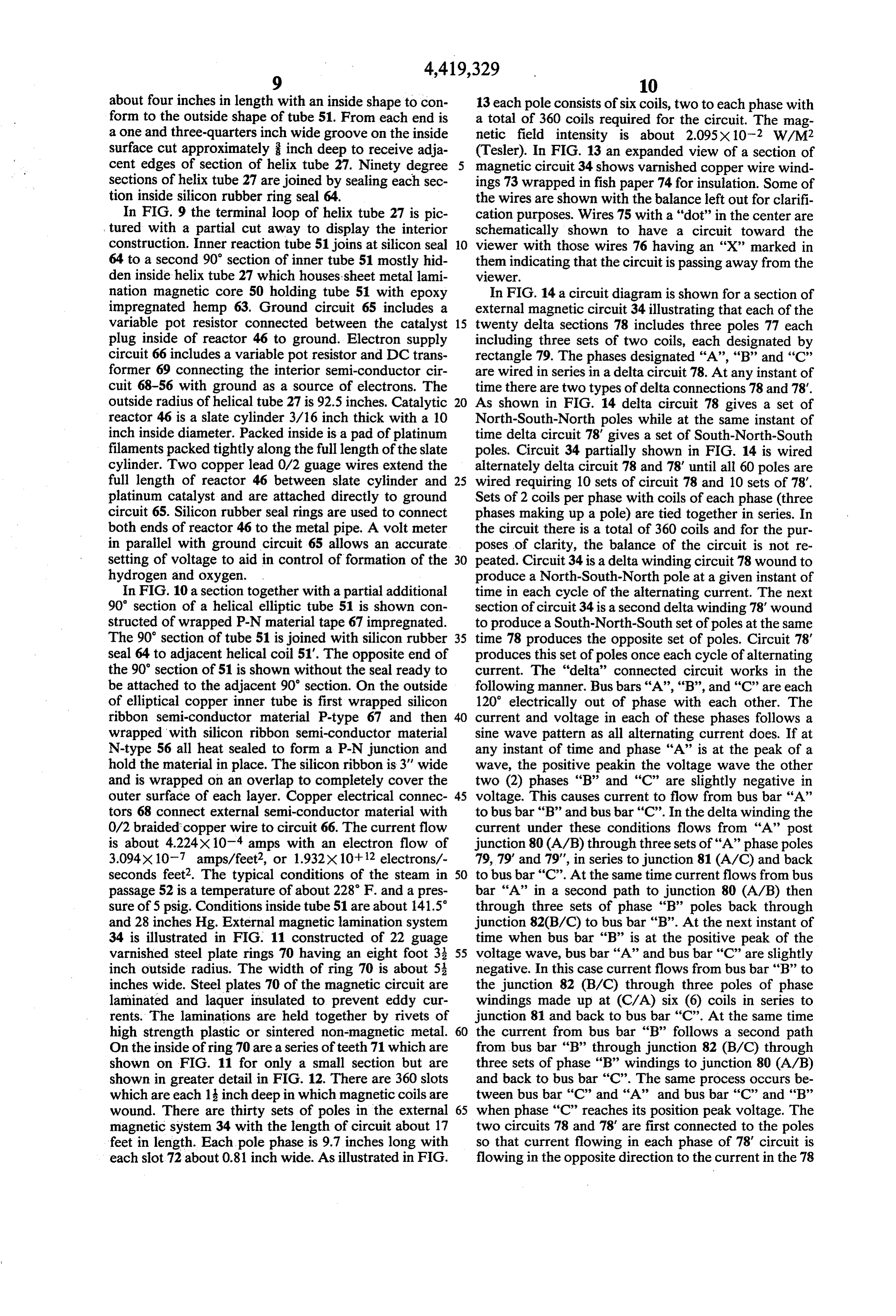
about four inches in length with an inside shape to con 13 each pole consists of six coils, two to each phase with form to the outside shape of tube 51. From each end is a total of 360 coils required for the circuit. The mag a one and three-quarters inch wide groove on the inside netic field intensity is about 2.095X 10⁻² W/M2 surface cut approximately inch deep to receive adja (Tesler). In FIG. 13 an expanded view of a section of cent edges of section of helix tube 27. Ninety degree magnetic circuit 34 shows varnished copper wire wind sections of helix tube 27 are joined by sealing each sec ings 73 wrapped in fish paper 74 for insulation. Some of tion inside silicon rubber ring seal 64. the wires are shown with the balance left out for clarifi In FIG. 9 the terminal loop of helix tube 27 is pic cation purposes. Wires 75 with a "dot" in the center are tured with a partial cut away to display the interior schematically shown to have a circuit toward the construction. Inner reaction tube 51 joins at silicon seal O viewer with those wires 76 having an “X” marked in 64 to a second 90 section of inner tube 51 mostly hid them indicating that the circuit is passing away from the den inside helix tube 27 which houses sheet metal lami Wewer.
nation magnetic core 50 holding tube 51 with epoxy In FIG. 14 a circuit diagram is shown for a section of impregnated hemp 63. Ground circuit 65 includes a external magnetic circuit 34 illustrating that each of the variable pot resistor connected between the catalyst 15 twenty delta sections 78 includes three poles 77 each plug inside of reactor 46 to ground. Electron supply including three sets of two coils, each designated by circuit 66 includes a variable pot resistor and DC trans rectangle 79. The phases designated “A”, “B” and “C” former 69 connecting the interior semi-conductor cir are wired in series in a delta circuit 78. At any instant of cuit 68-56 with ground as a source of electrons. The time there are two types of delta connections 78 and 78. outside radius of helical tube 27 is 92.5 inches. Catalytic 20 As shown in FIG. 14 delta circuit 78 gives a set of reactor 46 is a slate cylinder 3/16 inch thick with a 10 North-South-North poles while at the same instant of inch inside diameter. Packed inside is a pad of platinum time delta circuit 78' gives a set of South-North-South filaments packed tightly along the full length of the slate poles. Circuit 34 partially shown in FIG. 14 is wired cylinder. Two copper lead 0/2 guage wires extend the alternately delta circuit 78 and 78 until all 60 poles are full length of reactor 46 between slate cylinder and 25 wired requiring 10 sets of circuit 78 and 10 sets of 78. platinum catalyst and are attached directly to ground Sets of 2 coils per phase with coils of each phase (three circuit 65. Silicon rubber seal rings are used to connect phases making up a pole) are tied together in series. In both ends of reactor 46 to the metal pipe. A volt meter the circuit there is a total of 360 coils and for the pur in parallel with ground circuit 65 allows an accurate poses of clarity, the balance of the circuit is not re setting of voltage to aid in control of formation of the 30 peated. Circuit 34 is a delta winding circuit 78 wound to hydrogen and oxygen. . produce a North-South-North pole at a given instant of In FIG. 10 a section together with a partial additional time in each cycle of the alternating current. The next 90 section of a helical elliptic tube 51 is shown con section of circuit 34 is a second delta winding 78' wound structed of wrapped P-N material tape 67 impregnated. to produce a South-North-South set of poles at the same The 90' section of tube 51 is joined with silicon rubber 35 time 78 produces the opposite set of poles. Circuit 78 seal 64 to adjacent helical coil 51". The opposite end of produces this set of poles once each cycle of alternating the 90' section of 51 is shown without the seal ready to current. The "delta' connected circuit works in the be attached to the adjacent 90 section. On the outside following manner. Bus bars 'A', 'B', and 'C' are each of elliptical copper inner tube is first wrapped silicon 120 electrically out of phase with each other. The ribbon semi-conductor material P-type 67 and then current and voltage in each of these phases follows a wrapped with silicon ribbon semi-conductor material sine wave pattern as all alternating current does. If at N-type 56 all heat sealed to form a P-N junction and any instant of time and phase "A' is at the peak of a hold the material in place. The silicon ribbon is 3' wide wave, the positive peakin the voltage wave the other and is wrapped on an overlap to completely cover the two (2) phases “B” and "C" are slightly negative in outer surface of each layer. Copper electrical connec 45 voltage. This causes current to flow from bus bar 'A' tors 68 connect external semi-conductor material with to bus bar “B” and bus bar 'C'. In the delta winding the 0/2 braided copper wire to circuit 66. The current flow current under these conditions flows from “A” post is about 4.224x10 amps with an electron flow of junction 80 (A/B) through three sets of "A" phase poles 3.094x10⁻⁷ amps/feet2, or 1.932x10+12 electrons/- 79, 79' and 79', in series to junction 81 (A/C) and back seconds feet2. The typical conditions of the steam in 50 to bus bar 'C'. At the same time current flows from bus passage 52 is a temperature of about 228 F. and a pres bar "A' in a second path to junction 80 (A/B) then sure of 5 psig, Conditions inside tube 51 are about 141.5 through three sets of phase “B” poles back through and 28 inches Hg. External magnetic lamination system junction 82(B/C) to bus bar 'B'. At the next instant of 34 is illustrated in FIG. 11 constructed of 22 guage time when bus bar "B" is at the positive peak of the varnished steel plate rings 70 having an eight foot 3: 55 voltage wave, bus bar “A” and bus bar “C” are slightly inch outside radius. The width of ring 70 is about 5 negative. In this case current flows from bus bar “B” to inches wide. Steel plates 70 of the magnetic circuit are the junction 82 (B/C) through three poles of phase laminated and laquer insulated to prevent eddy cur windings made up at (C/A) six (6) coils in series to rents. The laminations are held together by rivets of junction 81 and back to bus bar 'C'. At the same time high strength plastic or sintered non-magnetic metal. 60 the current from bus bar “B” follows a second path On the inside of ring 70 are a series of teeth 71 which are from bus bar “B” through junction 82 (B/C) through shown on FIG. 11 for only a small section but are three sets of phase "B' windings to junction 80 (A/B) shown in greater detail in FIG. 12. There are 360 slots and back to bus bar 'C'. The same process occurs be which are each 1 inch deep in which magnetic coils are tween bus bar 'C' and 'A' and bus bar 'C' and 'B' wound. There are thirty sets of poles in the external 65 when phase "C' reaches its position peak voltage. The magnetic system 34 with the length of circuit about 17 two circuits 78 and 78' are first connected to the poles feet in length. Each pole phase is 9.7 inches long with so that current flowing in each phase of 78 circuit is each slot 72 about 0.81 inch wide. As illustrated in FIG. flowing in the opposite direction to the current in the 78
Page 13
circuit coils. The circuit is repetitive throughout along disassociate the compound into oxygen and combusti bus bars 37 with 240 volts between each bus bar (phase) ble gas, and 120 volts to ground. (g) collecting means to separate, collect and store the While I have described my invention in connection oxygen and fuel gases in separate containers, and with specific embodiments, it is to be clearly understood wherein the ionization means comprises a tube con that this description is made only by way of example struction of a semi-conductor N-function material on and not of limitation to the scope of my invention as set the outside and a P-function material on the next forth in the following claims. inside nearer but protected from the compound. I claim: 5. The apparatus of claim 4 wherein the tube is con 1. An apparatus to disassociate combustion product 10 structed of a sandwich laminate with an electrically compound into its component fuel part and oxygen conductive, non-magnetic metal on the inside surface gases comprising: with an N-function material on the outside surface of (a) a source of combustion product compound, the tube and a P-function material sandwiched in be (b) a tube to carry the compound, tween the two layers.
(c) acceleration means to cause the compound to accu 15 6. An apparatus to disassociate combustion product mulate a high level of velocity kinetic energy, com compound into fuel gas and oxygen gas comprising: prising an ionization means to continuously add ex (a) a Supply means for supplying the compound, cess electrons to the compound, (b) a tube to carry the compound, (d) a porous plug of catalytic metal in the tube in the (c) an external heat source to supply heat to the tube to path of the compound allowing the high velocity 20 increase the temperature of the compound flowing in compound to pass through the porous plug, and the tube, wherein the ionization means comprises the tube (d) ionization means for adding excess electrons to the constructed of a layer of semi-conductor N-function compound comprising the tube having constructed material on the outside, a P-function material layer on its outside surface construction of a semi-conduc next inside, and a non-magnetic layer on the inside in 25 tor having a P-N function with the P-function mate contact with the compound flow. rial laminated on the surface of the tube and the N 2. The apparatus of claim 1 wherein the ionization function material laminated on the outside of the means comprises a tube construction comprising P P-function material, function silicone ribbon semi-conductor on the inside (e) acceleration means comprising a sweeping magnetic and N-function silicone ribbon semi-conductor on the 30 field to accelerate the compound ions and to cause outside. the gaseous mass to accumulate high velocity kinetic 3. An apparatus to disassociate combustion product energy, and compound into its component fuel part and oxygen (f) a porous plug of catalyst metal means in the tube gases comprising: sealed in the path of the compound to cause the high (a) a source of combustion product compound, 35 velocity compound in passing through the porous (b) a tube to carry the compound, plug to split the compound ions to form oxygen and (c) acceleration means to cause the compound to accu fuel gases.
mulate a high level of velocity kinetic energy, com 7. The apparatus of claim 6 wherein the tube is a helix prising an ionization means to continuously add ex coil with an elliptical cross-section. cess electrons to the compound, 40 8. The apparatus of claim 6 wherein the tube is con (d) a porous plug of catalytic metal in the tube in the structed of a sandwich laminate with an electrically path of the compound allowing the high velocity conductive, non-magnetic metal on the inside surface compound to pass through the porous plug, and with an N-function material on the outside surface of wherein the tube is constructed of a sandwich lami the tube and a P-function material sandwiched in be nate with an electrically conductive, non-magnetic 45 tween the two layers.
metal on the inside surface with an N-function mate 9. The apparatus of claim 6 wherein the acceleration rial on the outside surface of the tube and a P-function means is a sweeping magnetic field to accelerate the material sandwiched in between the two layers. compound ions in a rotational flow pattern in a direc 4. An apparatus to disassociate combustion product tion not common to the transport flow of the compound compound into its component fuel part and oxygen 50 along the tube.
gases comprising: 10. The apparatus of claim 6 wherein the catalyst (a) a supply means for supplying the combustion prod metal means is a metal chosen form the group consisting uct compound, of platinum and palladium.
(b) a tube to carry the compound, 11. An apparatus to disassociate combustion product (c) an external heat source to supply heat to the tube to 55 compound into its fuel gas and oxygen gas components increase the temperature of the compound flowing in comprising:
the tube, (a) a tube to carry the compound in gaseous form, (d) ionization means for adding excess electrons to the (b) a heat source means to transfer heat to the com compound being carried in the tube, pound flowing inside the tube, (e) acceleration means comprising a rotating sweeping 60 (c) ionization means for adding excess electrons to the magnetic field to accelerate a swirling velocity to the compound in the tube comprising the tube con compound ions in a flow pattern not common with structed of a semi-conductor laminate P-function the transport flow of the compound along the tube, to material on the inside and N-function material on the achieve high velocity kinetic energy in the com outside, pound, 65 (d) a sweeping magnetic field means to accelerate the (f) a disassociation means to transfer the high velocity ionized compound ions and to cause the gaseous mass kinetic energy of the compound to increase the orbi to accumulate a swirling high velocity kinetic energy, tal energy of the atoms to a higher energy level and and
Page 14
(e) a porous plug of catalyst metal means in the tube the rotational flow of the compound ions being in a sealed in the path of the compound to cause the high direction not common to the flow of the compound kinetic energy compound to pass through the porous along the tube, plug during which the compound ions split to form (f) disassociation means to transfer the high velocity oxygen gas and fuel gas. 5 kinetic energy of the compound to increase the orbi 12. An apparatus to disassociate combustion product tal energy of the atoms to a higher energy level and compound comprising a compound chosen from the disassociate the compound into oxygen and combusti group consisting of water and a mixture of carbon diox ble gas comprising a plug of fine shreddings of plati ide and water into its hydrogen and oxygen gases com num metal in a slate cylinder; and prising: 10 (g) collecting means to separate, collect and store the (a) a helix coiled tube to carry the compound in gaseous oxygen and hydrogen gases. form, 13. An apparatus to disassociate combustion product (b) a heat source means to transfer heat to the com compound into its component fuel part and oxygen pound comprising a high temperature working fluid gases comprising:
in heat conductive relationship flowing parallel with 15 (a) a source of combustion product compound, the transport flow of the compound through the tube, (b) a tube to carry the compound, (c) ionization means for adding excess electrons to the (c) acceleration means to cause the compound to accu compound in the tube comprising the tube con mulate a high level of velocity kinetic energy, com structed of a sandwich laminate with an electrically prising an ionization means to add excess electrons to conductive, non-magnetic metal layer on the inside 20 the compound, comprising a tube constructed of a surface with an N-function material layer on the out sandwich laminate with an electrically conductive, side surface of the tube and a P-function material non-magnetic metal on the inside surface with an sandwiched in between the two layers, N-function material on the outside surface of the tube (d) a controlled circuit means electrically connected and a P-function material sandwiched in between the with the ionization means for controlling the adding 25 two layers, of excess electrons to the compound, (d) a porous plug of catalytic metal in the tube in the (e) a sweeping magnetic field means to accelerate the path of the compound allowing the high velocity ionized compound ions and to cause the gaseous mass compound to pass through the porous plug. to accumulate a swirling high velocity kinetic energy, k k :k k
Provenance
- Collection
- Cited prior art
- Original PDF
- patentimages.storage.googleapis.com →
- Filed
- 1982-04-15
- Pages
- 14
- Method
- pdftotext (the PDF's own text layer) + pdftoppm 300dpi page scans
- Source
- Google Patents bibliographic record
- Granted
- 1983-12-06
- Inventors
- Charles H. Heller
- Transcribed from
- patentimages.storage.googleapis.com →