patent · US4053576
System for obtaining hydrogen and oxygen from water using solar energy
11 October 1977
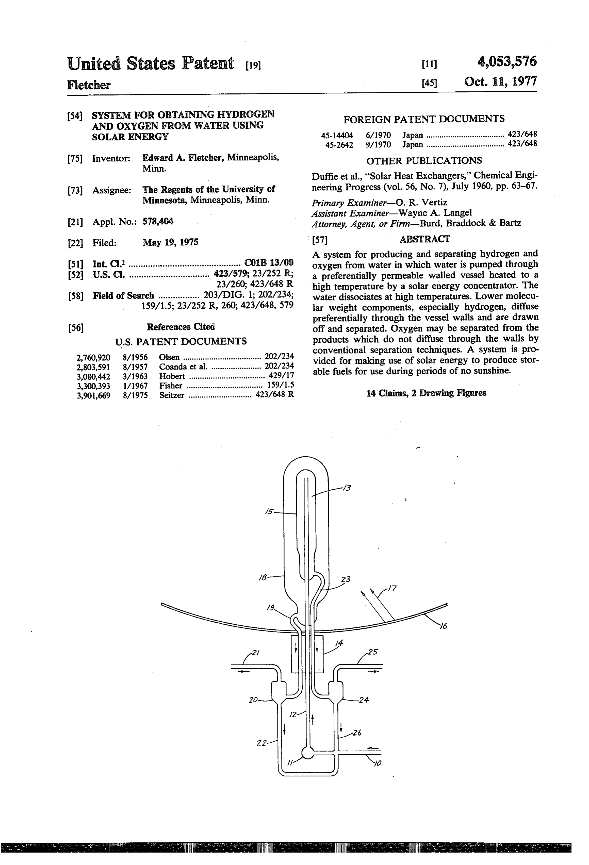
Page 1 — bibliographic record
United States Paterat (19) (11) 4,053,576 Fletcher 45) Oct. 11, 1977 54 SYSTEM FOR oBTAINING HYDROGEN
SOLAR ENERGY 45-14404 6/1970 Japan .................................... 423/648 45-2642 9/1970 Japan .................................... 423/648 75 Inventor: Ed A. Fletcher, Minneapolis, OTHER PUBLICATIONS Duffie et al., "Solar Heat Exchangers,” Chemical Engi 73) Assignee: The Regents of the University of neering Progress (vol. 56, No. 7), July 1960, pp. 63-67. Minnesota, Minneapolis, Minn. Primary Examiner-O. R. Vertiz
Assistant Examiner-Wayne A. Langel (21) Appl. No.: 578,404 Attorney, Agent, or Firm-Burd, Braddock & Bartz 22 Filed: May 19, 1975 (57) ABSTRACT A system for producing and separating hydrogen and 5ll Int. C.’.............................................. COB 13/00 oxygen from water in which water is pumped through 52 U.S. C. ................................. ';. 57. a preferentially permeable walled vessel heated to a high temperature by a solar energy concentrator. The 58) Field of Search ................. 203/DIG. 1; 202/234; water dissociates at high temperatures. Lower molecu 159/1.5; 23/252 R, 260; 423/648,579 lar weight components, especially hydrogen, diffuse preferentially through the vessel walls and are drawn (56) References Cited off and separated. Oxygen may be separated from the
2,760,920 8/1956 Olsen .................................. conventional separation techniques. A system is pro 206 si6s, ca". 2073 vided for making use of solar energy to produce stor 3,080,442 3/1963 Hobert ................................... 297, able fuels for use during periods of no sunshine. 3,300,393 1/1967 Fisher ................................... 159/1.5 3,901,669 8/1975 Seitzer ............................. 423/648 R 14 Claims, 2 Drawing Figures
Page 2
Drawing sheet — no readable text.
Page 3
Drawing sheet — no readable text.
Page 4
SYSTEM FOR OBTAINING HYDROGEN AND DESCRIPTION OF THE DRAWINGS OXYGEN FROM WATER USING SOLAR ENERGY The invention is illustrated in the accompanying drawings in which:
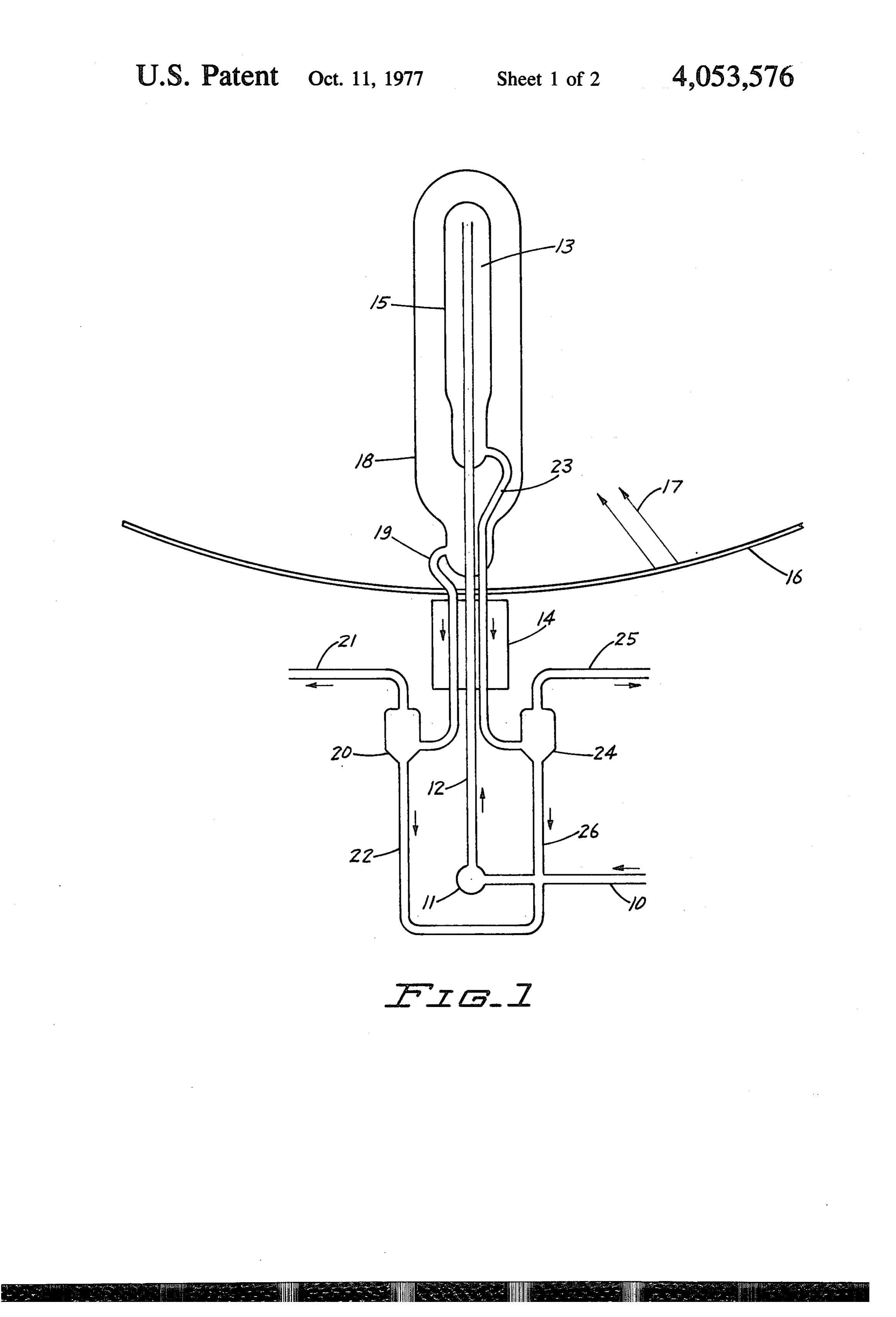
This invention is directed to a system for making use FIG. 1 is a schematic representation of one form of of solar energy to produce storable fuels by producing system for production and separation of hydrogen and and separating hydrogen and oxygen from water. oxygen from water by use of solar energy, and
BACKGROUND OF THE INVENTION
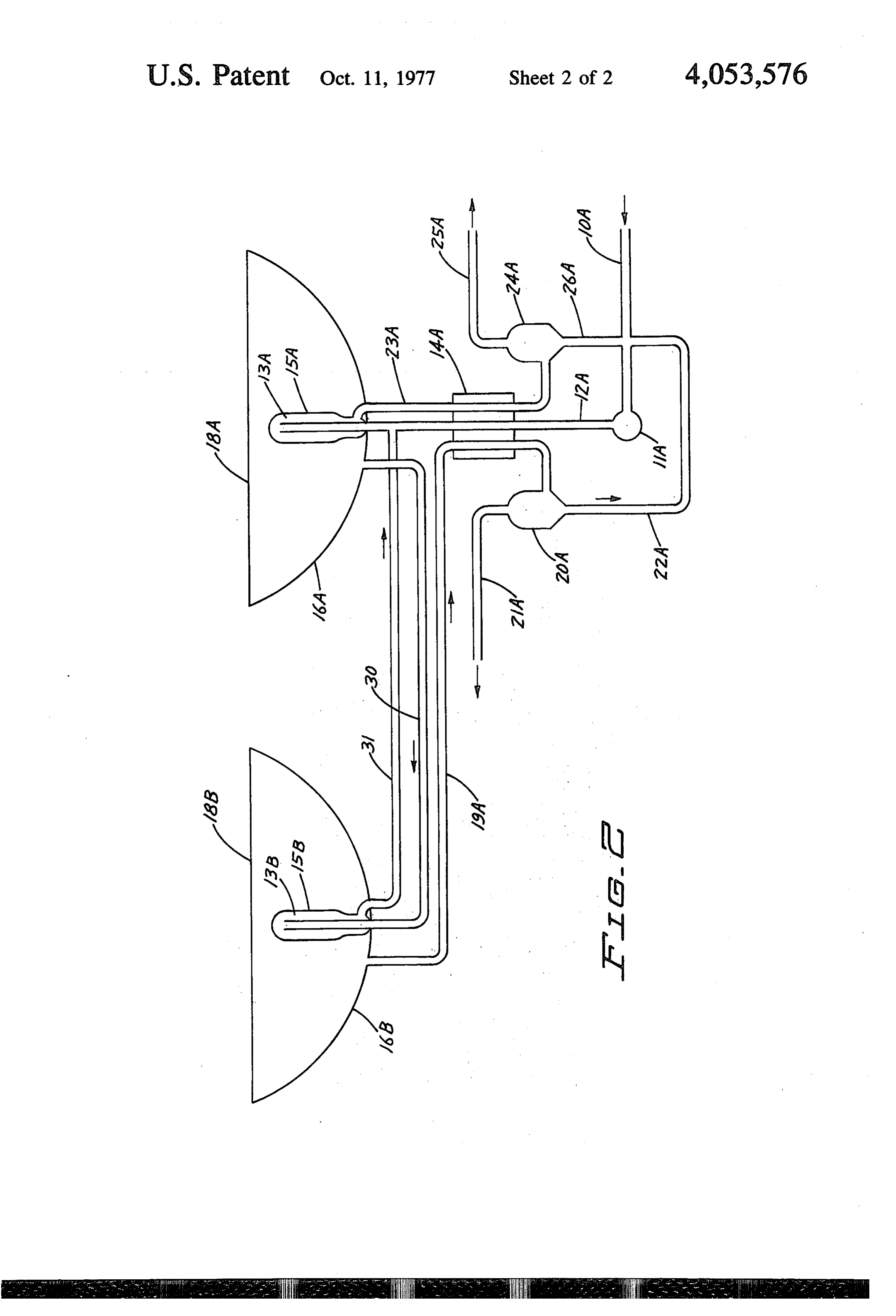
FIG. 2 is a schematic representation of another form of system for the same purpose.
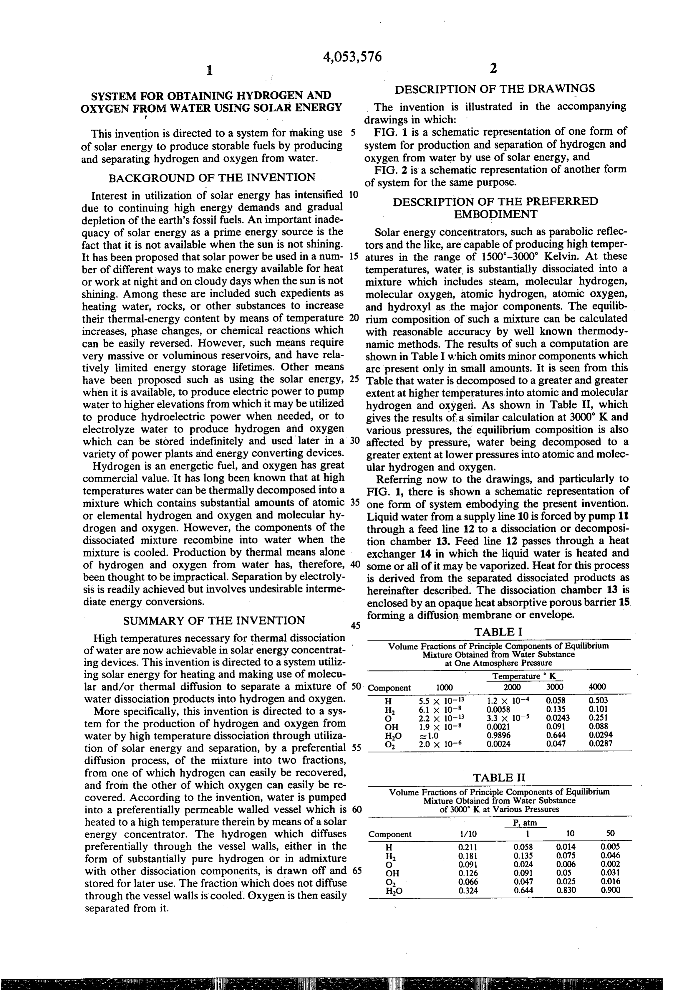
Interest in utilization of solar energy has intensified 10 DESCRIPTION OF THE PREFERRED due to continuing high energy demands and gradual EMBODIMENT depletion of the earth's fossil fuels. An important inade quacy of solar energy as a prime energy source is the Solar energy concentrators, such as parabolic reflec fact that it is not available when the sun is not shining. tors and the like, are capable of producing high temper It has been proposed that solar power be used in a num 15 atures in the range of 1500-3000' Kelvin. At these ber of different ways to make energy available for heat temperatures, water is substantially dissociated into a or work at night and on cloudy days when the sun is not mixture which includes steam, molecular hydrogen, shining. Among these are included such expedients as molecular oxygen, atomic hydrogen, atomic oxygen, heating water, rocks, or other substances to increase and hydroxyl as the major components. The equilib their thermal-energy content by means of temperature 20 rium composition of such a mixture can be calculated increases, phase changes, or chemical reactions which with reasonable accuracy by well known thermody can be easily reversed. However, such means require namic methods. The results of such a computation are very massive or voluminous reservoirs, and have rela shown in Table I which omits minor components which tively limited energy storage lifetimes. Other means are present only in small amounts. It is seen from this have been proposed such as using the solar energy, 25 Table that water is decomposed to a greater and greater when it is available, to produce electric power to pump extent at higher temperatures into atomic and molecular water to higher elevations from which it may be utilized hydrogen and oxygeri. As shown in Table II, which to produce hydroelectric power when needed, or to gives the results of a similar calculation at 3000 K and electrolyze water to produce hydrogen and oxygen various pressures, the equilibrium composition is also which can be stored indefinitely and used later in a 30 affected by pressure, water being decomposed to a variety of power plants and energy converting devices. greater extent at lower pressures into atomic and molec Hydrogen is an energetic fuel, and oxygen has great ular hydrogen and oxygen.
commercial value. It has long been known that at high Referring now to the drawings, and particularly to temperatures water can be thermally decomposed into a FIG. 1, there is shown a schematic representation of mixture which contains substantial amounts of atomic 35 one form of system embodying the present invention. or elemental hydrogen and oxygen and molecular hy Liquid water from a supply line 10 is forced by pump 11 drogen and oxygen. However, the components of the through a feed line 12 to a dissociation or decomposi dissociated mixture recombine into water when the tion chamber 13. Feed line 12 passes through a heat mixture is cooled. Production by thermal means alone exchanger 14 in which the liquid water is heated and of hydrogen and oxygen from water has, therefore, some or all of it may be vaporized. Heat for this process been thought to be impractical. Separation by electroly is derived from the separated dissociated products as sis is readily achieved but involves undesirable interme hereinafter described. The dissociation chamber 13 is diate energy conversions. enclosed by an opaque heat absorptive porous barrier 15 SUMMARY OF THE INVENTION forming a diffusion membrane or envelope.
TABLE I
High temperatures necessary for thermal dissociation Volume Fractions of Principle Components of Equilibrium of water are now achievable in solar energy concentrat Mixture Obtained from Water Substance ing devices. This invention is directed to a system utiliz at One Atmosphere Pressure ing solar energy for heating and making use of molecu Temperature K. lar and/or thermal diffusion to separate a mixture of 50 Component 1000 2000 3000 4000 water dissociation products into hydrogen and oxygen. H 5.5 x 10⁻¹³ 1.2 x 10⁻⁴ 0.058 0.503 More specifically, this invention is directed to a sys H 6.1 x 10⁻⁸ 0.0058 0.13S 0.101
tem for the production of hydrogen and oxygen from OH 1.9 x 10⁻⁸ 0.0021 0.091 0.088 water by high temperature dissociation through utiliza HO at 1.0 0.9896 0.644 0.0294 tion of solar energy and separation, by a preferential 55 O 2.0 x 10⁻⁶ 0.0024 0.047 0.0287 diffusion process, of the mixture into two fractions, from one of which hydrogen can easily be recovered, TABLE II and from the other of which oxygen can easily be re Volume Fractions of Principle Components of Equilibrium covered. According to the invention, water is pumped Mixture Obtained from Water Substance into a preferentially permeable walled vessel which is of 3000 K at Various Pressures heated to a high temperature therein by means of a solar P, atm energy concentrator. The hydrogen which diffuses Component 1/10 1 10 50 preferentially through the vessel walls, either in the H 0.211 0.058 0,014 0.005 form of substantially pure hydrogen or in admixture H 0.18 0.135 0.075 0.046
with other dissociation components, is drawn off and 65 OHO
stored for later use. The fraction which does not diffuse HO 0.324 0.644 0,830 0.900 through the vessel walls is cooled. Oxygen is then easily separated from it.
Page 5
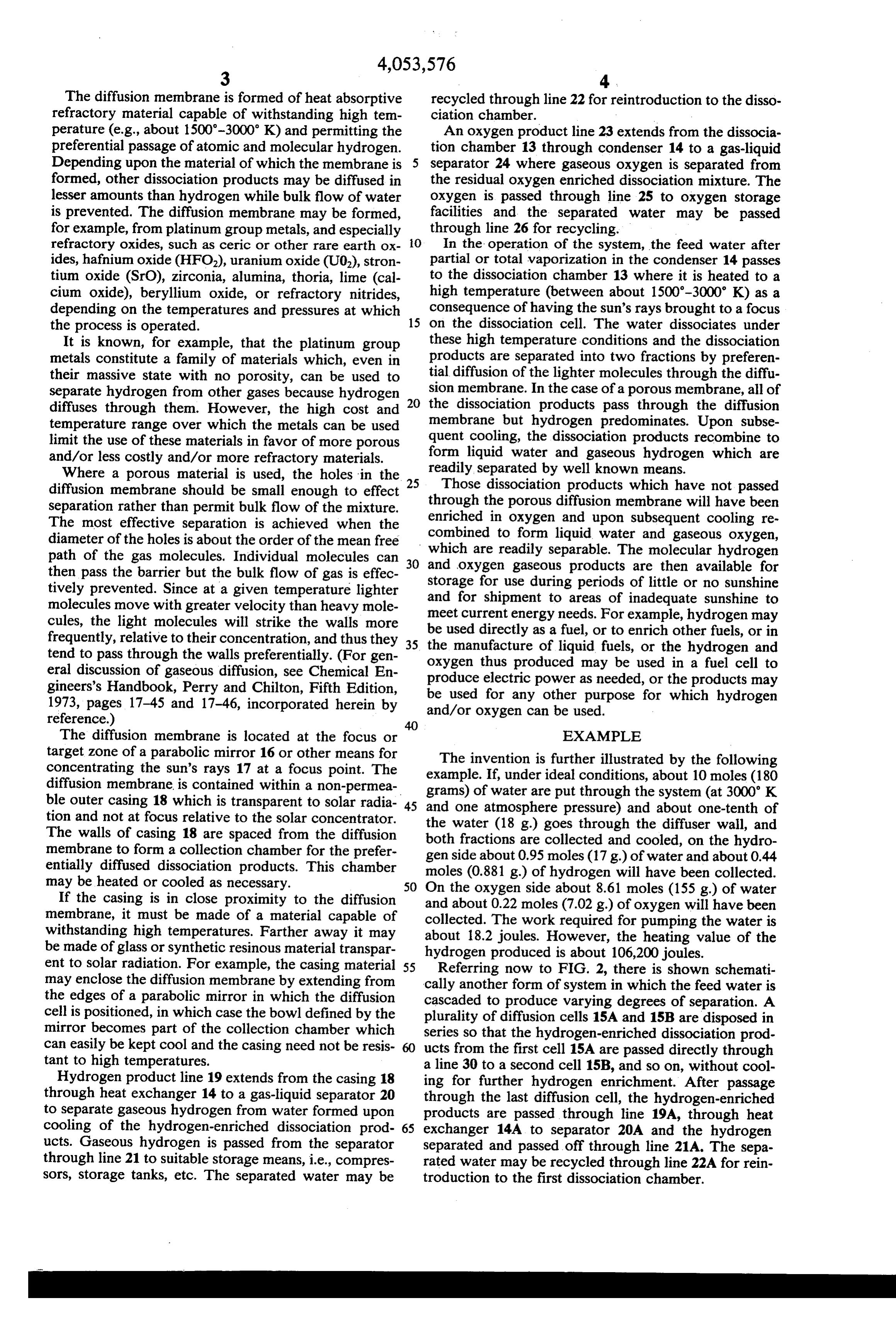
The diffusion membrane is formed of heat absorptive recycled through line 22 for reintroduction to the disso refractory material capable of withstanding high tem ciation chamber.
perature (e.g., about 1500-3000 K) and permitting the An oxygen product line 23 extends from the dissocia preferential passage of atomic and molecular hydrogen. tion chamber 13 through condenser 14 to a gas-liquid Depending upon the material of which the membrane is 5 separator 24 where gaseous oxygen is separated from formed, other dissociation products may be diffused in the residual oxygen enriched dissociation mixture. The lesser amounts than hydrogen while bulk flow of water oxygen is passed through line 25 to oxygen storage is prevented. The diffusion membrane may be formed, facilities and the separated water may be passed for example, from platinum group metals, and especially through line 26 for recycling.
refractory oxides, such as ceric or other rare earth ox- 10 In the operation of the system, the feed water after ides, hafnium oxide (HFO2), uranium oxide (U02), stron partial or total vaporization in the condenser 14 passes tium oxide (SrC), zirconia, alumina, thoria, line (cal to the dissociation chamber 13 where it is heated to a cium oxide), beryllium oxide, or refractory nitrides, high temperature (between about 1500-3000 K) as a depending on the temperatures and pressures at which consequence of having the sun's rays brought to a focus the process is operated. 15 on the dissociation cell. The water dissociates under It is known, for example, that the platinum group these high temperature conditions and the dissociation metals constitute a family of materials which, even in products are separated into two fractions by preferen their massive state with no porosity, can be used to tial diffusion of the lighter molecules through the diffu separate hydrogen from other gases because hydrogen 20 sion membrane. In the case of a porous membrane, all of diffuses through them. However, the high cost and the dissociation products pass through the diffusion temperature range over which the metals can be used membrane but hydrogen predominates. Upon subse limit the use of these materials in favor of more porous quent cooling, the dissociation products recombine to and/or less costly and/or more refractory materials. form liquid water and gaseous hydrogen which are Where a porous material is used, the holes in the 25 readily Those separated by well known means.
dissociation products which have not passed diffusion membrane should be small enough to effect through the separation rather than permit bulk flow of the mixture. enriched in porous oxygen diffusion membrane will have been and upon subsequent cooling re
The most effective separation is achieved when the combined to form liquid water and gaseous oxygen, diameter of the holes is about the order of the mean free path of the gas molecules. Individual molecules can 30 and oxygen gaseous productsThearemolecular which are readily separable.
then hydrogen available for then pass the barrier but the bulk flow of gas is effec storage for use during periods of little or no sunshine tively prevented. Since at a given temperature lighter molecules move with greater velocity than heavy mole and meet for shipment to areas of inadequate sunshine to current energy needs. For example, hydrogen may cules, the light molecules will strike the walls more be used directly as a fuel, or to enrich other fuels, or in frequently, relative to their concentration, and thus they is the manufacture of liquid fuels, or the hydrogen and tend to pass through the walls preferentially. (For gen oxygen thus produced may be used in a fuel cell to eral discussion of gaseous diffusion, see Chemical En produce electric power as needed, or the products may gineers's Handbook, Perry and Chilton, Fifth Edition, be used for any other purpose for which hydrogen 1973, pages 17-45 and 17-46, incorporated herein by and/or oxygen can be used.
The diffusion membrane is located at the focus or EXAMPLE target zone of a parabolic mirror 16 or other means for The invention is further illustrated by the following concentrating the sun's rays 17 at a focus point. The example. If, under ideal conditions, about 10 moles (180 diffusion membrane is contained within a non-permea grams) of water are put through the system (at 3000 K ble outer casing 18 which is transparent to solar radia-45 and one atmosphere pressure) and about one-tenth of tion and not at focus relative to the solar concentrator. the water (18 g) goes through the diffuser wall, and The walls of casing 18 are spaced from the diffusion both fractions are collected and cooled, on the hydro membrane to form a collection chamber for the prefer gen side about 0.95 moles (17 g) of water and about 0.44 entially diffused dissociation products. This chamber moles (0.881 g) of hydrogen will have been collected. may be heated or cooled as necessary. 50 On the oxygen side about 8.61 moles (155 g) of water If the casing is in close proximity to the diffusion and about 0.22 moles (7.02 g) of oxygen will have been membrane, it must be made of a material capable of collected. The work required for pumping the water is withstanding high temperatures. Farther away it may be made of glass or synthetic resinous material transpar about 18.2 joules. However, the heating value of the hydrogen produced is about 106,200 joules.
ent to solar radiation. For example, the casing material 55 Referring now to FIG. 2, there is shown schemati may enclose the diffusion membrane by extending from cally another form of system in which the feed water is the edges of a parabolic mirror in which the diffusion cascaded to produce varying degrees of separation. A cell is positioned, in which case the bowl defined by the plurality of diffusion cells 15A and 15B are disposed in mirror becomes part of the collection chamber which series so that the hydrogen-enriched dissociation prod can easily be kept cool and the casing need not be resis- 60 ucts from the first cell 15A are passed directly through tant to high temperatures. a line 30 to a second cell 15B, and so on, without cool Hydrogen product line 19 extends from the casing 18 ing for further hydrogen enrichment. After passage through heat exchanger 14 to a gas-liquid separator 20 through the last diffusion cell, the hydrogen-enriched to separate gaseous hydrogen from water formed upon products are passed through line 19A, through heat cooling of the hydrogen-enriched dissociation prod- 65 exchanger 14A to separator 20A and the hydrogen ucts. Gaseous hydrogen is passed from the separator separated and passed off through line 21A. The sepa through line 21 to suitable storage means, i.e., compres rated water may be recycled through line 22A for rein sors, storage tanks, etc. The separated water may be troduction to the first dissociation chamber.
Page 6
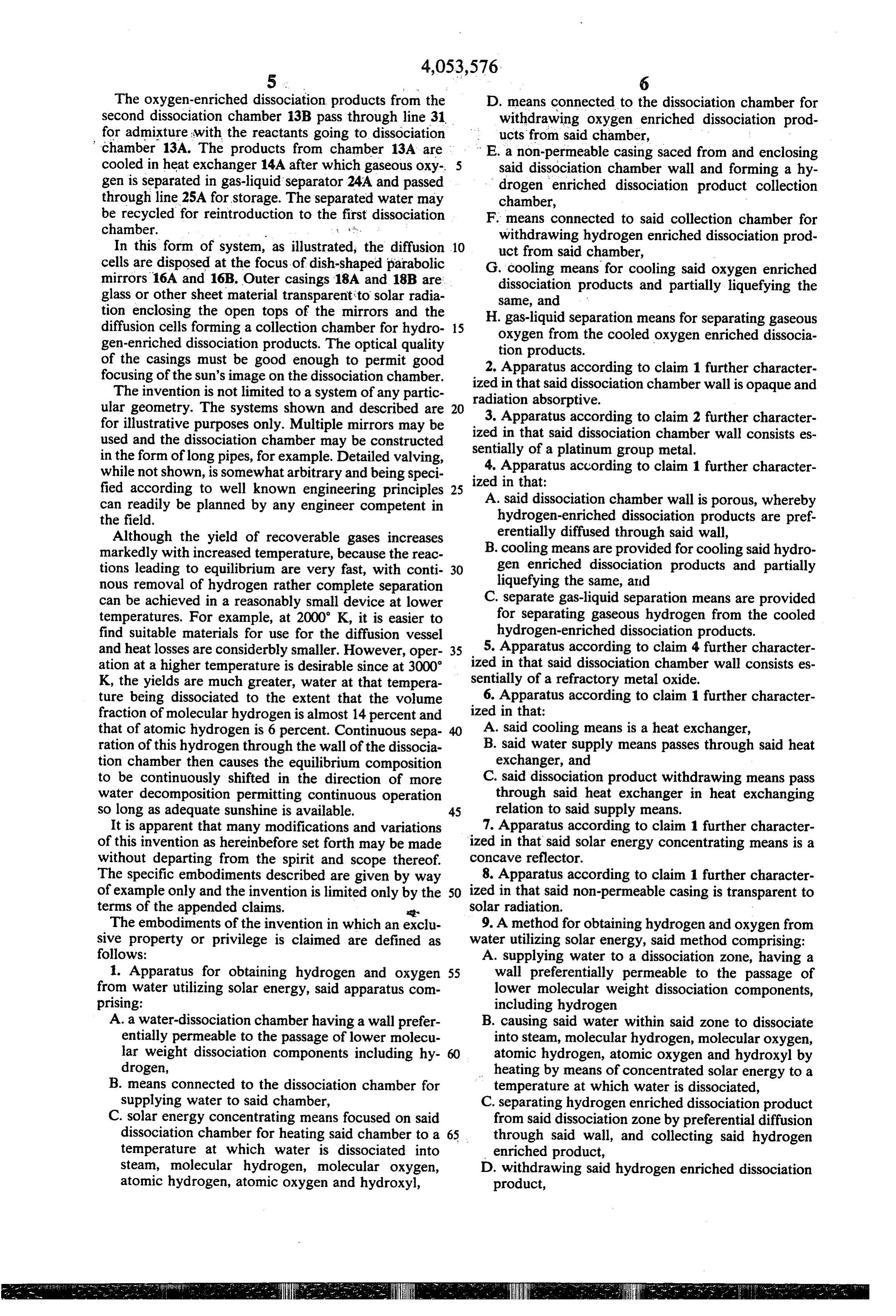
The oxygen-enriched dissociation products from the D. means connected to the dissociation chamber for second dissociation chamber 13B pass through line 31 withdrawing oxygen enriched dissociation prod for admixture with the reactants going to dissociation ucts from said chamber, chamber 13A. The products from chamber 13A are E. a non-permeable casing saced from and enclosing cooled in heat exchanger 14A after which gaseous oxy said dissociation chamber wall and forming a hy gen is separated in gas-liquid separator 24A and passed drogen enriched dissociation product collection through line 25A for storage. The separated water may chamber, be recycled for reintroduction to the first dissociation F. means connected to said collection chamber for chamber. withdrawing hydrogen enriched dissociation prod In this form of system, as illustrated, the diffusion 10 uct from said chamber, cells are disposed at the focus of dish-shaped parabolic G. cooling means for cooling said oxygen enriched mirrors 16A and 16B. Outer casings 18A and 18B are: dissociation products and partially liquefying the glass or other sheet material transparent to solar radia same, and tion enclosing the open tops of the mirrors and the H. gas-liquid separation means for separating gaseous diffusion cells forming a collection chamber for hydro 15 oxygen from the cooled oxygen enriched dissocia gen-enriched dissociation products. The optical quality tion products.
of the casings must be good enough to permit good focusing of the sun's image on the dissociation chamber. ized Apparatus 2. according to claim 1 further character in that said dissociation chamber wall is opaque and
The invention is not limited to a system of any partic radiation absorptive.
ular geometry. The systems shown and described are 20 3. Apparatus for illustrative purposes only. Multiple mirrors may be ized in that saidaccording to claim 2 further character dissociation chamber wall consists es used and the dissociation chamber may be constructed in the form of long pipes, for example. Detailed valving, sentially of a platinum group metal. while not shown, is somewhat arbitrary and being speci ized in that: according to claim 1 further character 4. Apparatus fied according to well known engineering principles 25 can readily be planned by any engineer competent in A. said dissociation chamber wall is porous, whereby the field. hydrogen-enriched dissociation products are pref. Although the yield of recoverable gases increases erentially diffused through said wall, markedly with increased temperature, because the reac B. cooling means are provided for cooling said hydro tions leading to equilibrium are very fast, with conti 30 gen enriched dissociation products and partially nous removal of hydrogen rather complete separation liquefying the same, and can be achieved in a reasonably small device at lower C. separate gas-liquid separation means are provided temperatures. For example, at 2000 K, it is easier to for separating gaseous hydrogen from the cooled find suitable materials for use for the diffusion vessel hydrogen-enriched dissociation products. and heat losses are considerbly smaller. However, oper 35 5. Apparatus according to claim 4 further character ation at a higher temperature is desirable since at 3000 ized in that said dissociation chamber wall consists es K, the yields are much greater, water at that tempera sentially of a refractory metal oxide. ture being dissociated to the extent that the volume ized 6. Apparatus according to claim 1 further character fraction of molecular hydrogen is almost 14 percent and in that:
that of atomic hydrogen is 6 percent. Continuous sepa A. said cooling means is a heat exchanger, ration of this hydrogen through the wall of the dissocia B. said water supply means passes through said heat tion chamber then causes the equilibrium composition exchanger, and to be continuously shifted in the direction of more C. said dissociation product withdrawing means pass water decomposition permitting continuous operation through said heat exchanger in heat exchanging so long as adequate sunshine is available. 45 relation to said supply means. It is apparent that many modifications and variations 7. Apparatus according to claim 1 further character of this invention as hereinbefore set forth may be made ized in that said solar energy concentrating means is a without departing from the spirit and scope thereof. concave reflector.
The specific embodiments described are given by way 8. Apparatus according to claim 1 further character of example only and the invention is limited only by the 50 ized in that said non-permeable casing is transparent to terms of the appended claims. ar solar radiation.
The embodiments of the invention in which an exclu 9. A method for obtaining hydrogen and oxygen from sive property or privilege is claimed are defined as water utilizing solar energy, said method comprising: follows: A. supplying water to a dissociation zone, having a 1. Apparatus for obtaining hydrogen and oxygen 55 wall preferentially permeable to the passage of from water utilizing solar energy, said apparatus com lower molecular weight dissociation components, prising: including hydrogen
A. a water-dissociation chamber having a wall prefer B. causing said water within said zone to dissociate entially permeable to the passage of lower molecu into steam, molecular hydrogen, molecular oxygen, lar weight dissociation components including hy atomic hydrogen, atomic oxygen and hydroxyl by drogen, heating by means of concentrated solar energy to a B. means connected to the dissociation chamber for temperature at which water is dissociated, supplying water to said chamber, C. separating hydrogen enriched dissociation product C. solar energy concentrating means focused on said from said dissociation zone by preferential diffusion dissociation chamber for heating said chamber to a 65 through said wall, and collecting said hydrogen temperature at which water is dissociated into enriched product, steam, molecular hydrogen, molecular oxygen, D. withdrawing said hydrogen enriched dissociation atomic hydrogen, atomic oxygen and hydroxyl, product,
are:gs: its
Page 7
E. withdrawing oxygen enriched dissociation prod 12. A method according to claim 9 further character ucts remaining in said dissociation zone and cooling ized
in that:
the hydrogen enriched dissociation products are to liquefy a portion of the same, and
F. separating gaseous oxygen from the resulting mix 5 B.cooled to reliquefy a portion of the same, and gaseous hydrogen is separated from the resulting ture. mixture.
10. A method according to claim 9 further character 13. A method according to claim 12 further charac ized in that said water is at least partially vaporized terized in that the liquefied dissociation mixture from prior to introduction to said dissociation zone. which hydrogen and oxygen have been separated is 11. A method according to claim 10 further charac 10 recyled to said dissociation zone. terized in that said water is at least partially vaporized 14. A method according to claim 9 further character and said dissociation products are cooled by passage of ized in that said water is heated to a dissociation temper the water and said dissociation products in heat ex ature between aboutk 1500' .
changing relation.
Page 8
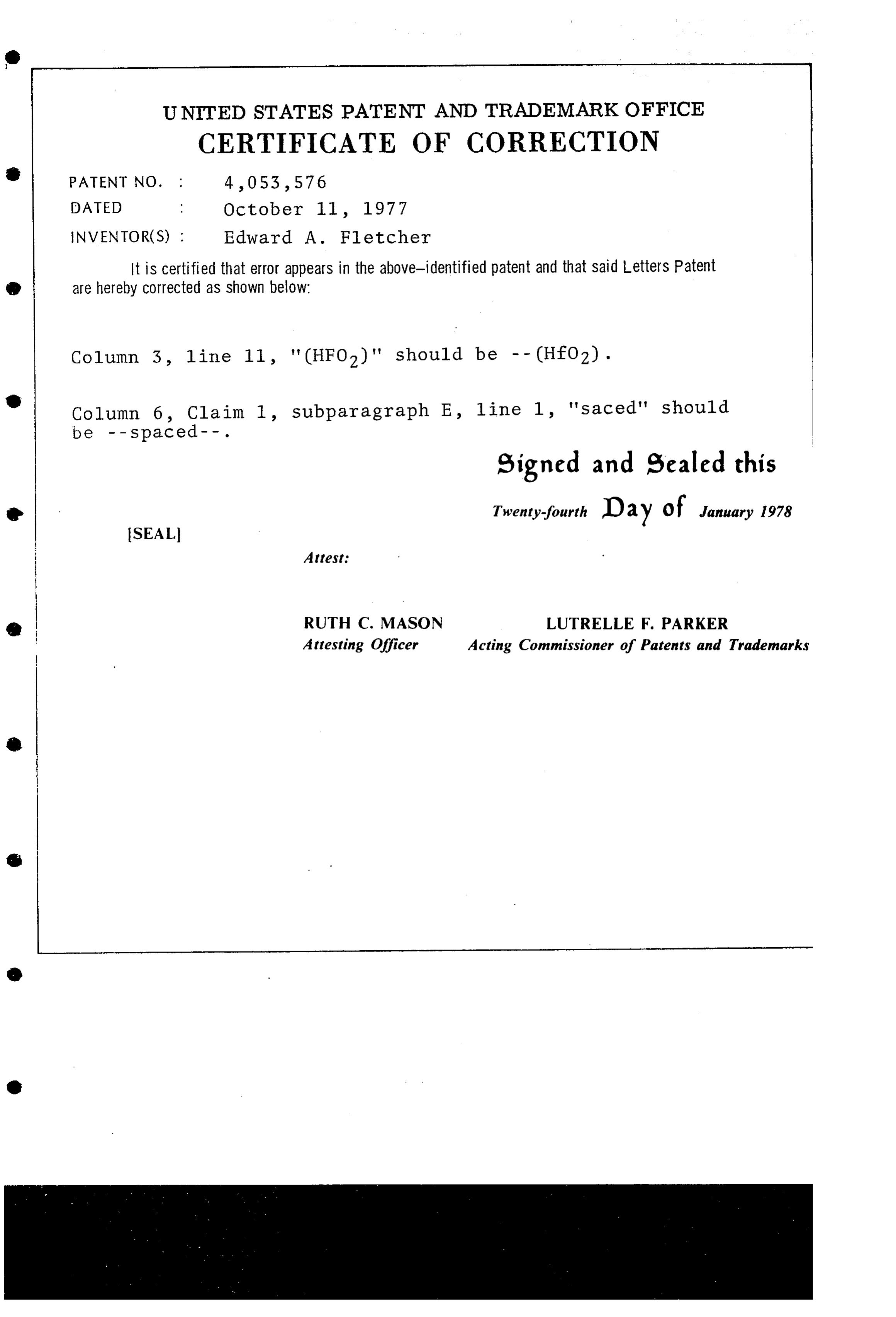
UNITED STATES PATENT AND TRADEMARK OFFICE
CERTIFICATE OF CORRECTION
NVENTOR(S) : Edward A. Fletcher
It is Certified that error appears in the above-identified patent and that said Letters Patent are hereby Corrected as shown below:
Column 3, line 11, "(HFO2)" should be -- (HfO2). Column 6, Claim 1, subparagraph E, line l, "Saced" should
signed and sealed this
Twenty-fourth Day of January 1978
SEAL
Attesting Officer Acting Commissioner of Patents and Trademarks
Page 9
UNITED STATES PATENT AND TRADEMARK OFFICE
CERTIFICATE OF CORRECTION
NVENTOR(S) : Edward A. Fletcher
It is Certified that error appears in the above-identified patent and that said Letters Patent are hereby corrected as shown below:
Column 3, line 11, "(HFO2)" should be -- (HfO2).
Column 6, Claim 1, subparagraph E, line 1, 'Saced' should
signed and Sealed this
O Twenty-fourth Day of January 1978
SEAL
Attest:
(t RUTH C. MASON LUTRELLE F. PARKER Attesting Officer Acting Commissioner of Patents and Trademarks
Provenance
- Collection
- Cited prior art
- Original PDF
- patentimages.storage.googleapis.com →
- Filed
- 1975-05-19
- Pages
- 9
- Method
- pdftotext (the PDF's own text layer) + pdftoppm 300dpi page scans
- Source
- Google Patents bibliographic record
- Granted
- 1977-10-11
- Inventors
- Edward A. Fletcher; University of Minnesota System
- Transcribed from
- patentimages.storage.googleapis.com →