patent · US4366856
Apparatus for storing heat
4 January 1983
Page 1 — bibliographic record
United States Patent (19) (11) 4,366,856 Yamadori et al. 45) Jan. 4, 1983 (54) APPARATUS FOR STORING HEAT 2,907,183 10/1959 Roberts ............................. 62/351 x 2,941,377 6/1960 Nelson .............................. 62/351 X (75) Inventors: Michio Yamadori, Hachioji; Kohji 3,997,001 12/1976 Chubb ..... ... 165/104.7 X Kamejima, Shimoinayoshi; Hideki 4,271,681 6/1981 Sehertz M. 65/104.17 X Tanaka, Shimoinayoshi; Minoru
Kano, Shimoinayoshi; Motokazu Primary Examiner-Albert W. Davis, Jr.
Uchida, Tokyo; Yoritsune Abe, Attorney, Agent, or Firm-Antonelli, Terry & Wands Ohiramachi, all of Japan 57 ABSTRACT 73) Assignee: Hitachi, Ltd., Tokyo, Japan A heat exchanger for cooling is immersed in a vessel for 21) Appl. No.: 212,341 storing heat filled with a heat-storing material of latent heat type. The heat exchanger for cooling is positioned 22 Filed: Dec. 3, 1980 at an upper level in the vessel when a heat-storing mate 30 Foreign Application Priority Data rial having a higher specific gravity in a crystal state Dec. 5, 1979 JP Japan ................................ 54-156810 than in a liquid state, such as calcium chloride hexahy drate, is used, whereas at a lower level in the vessel 51) Int. C. .............................................. F28D 21/00 when a heat-storing material having a lower specific 52 U.S. Cl. ................................. 165/104.17; 165/10; gravity in a cystal state than in a liquid state such as
58) Field of Search ...................... 165/104.17, 104.11; Crystals of a heat-storing material formed and deposited 62/351, 73, 352 on the outer periphery of the heat exchanger for cool 56) References Cited ing when the apparatus for storing heat is in operation
1,936,575 11/1933 Barret et al. ...................... 62/351 X 18 Claims, 14 Drawing Figures
Page 2
Drawing sheet — no readable text.
Page 3
Drawing sheet — no readable text.
Page 4
Drawing sheet — no readable text.
Page 5
Drawing sheet — no readable text.
Page 6
riphery of a heat exchanger in a vessel for storing heat
APPARATUS FOR STORING HEAT in a divided manner.
The present apparatus for storing heat can accumu
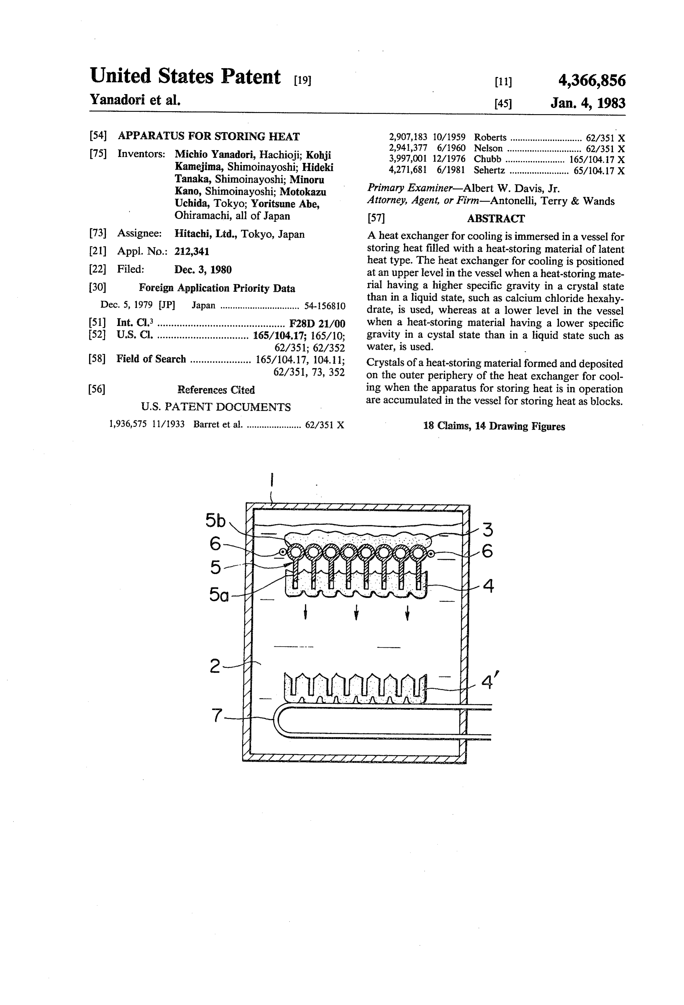
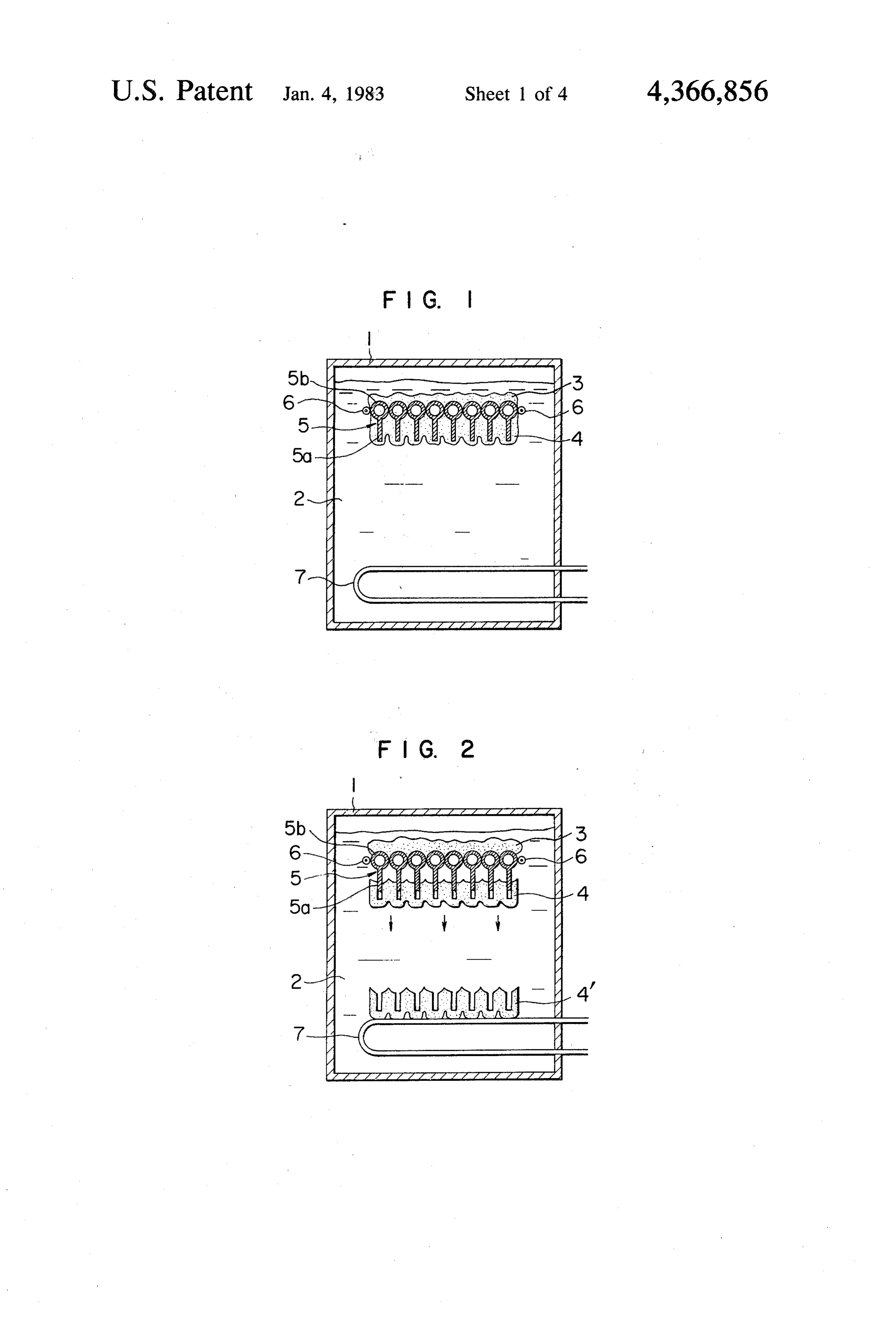
BACKGROUND OF THE INVENTION late crystals of heat-storing material deposited on the 1. Field of the Invention periphery of a heat exchanger in a vessel for storing This invention relates to an apparatus for storing heat in a regular manner as rectangular blocks therein. heat, which comprises a heat exchanger for cooling BRIEF DESCRIPTION OF THE DRAWINGS immersed in a heat-storing material of the latent heat type in a vessel for storing heat, and the present appara FIGS. 1 and 2 are cross-sectional views of an embodi tus for storing heat can be utilized in air conditioners of 10 ment of an apparatus for storing heat according to the the heat, pump type, heat-storing cooler-heaters, etc. present invention.
2. Description of the Prior Art FIG. 3 is a plan view of an embodiment of a heat Generally, an apparatus of the latent heat type for exchanger for cooling in the apparatus for storing heat storing heat has a vessel for storing heat, which is filled shown in FIGS. 1 and 2.
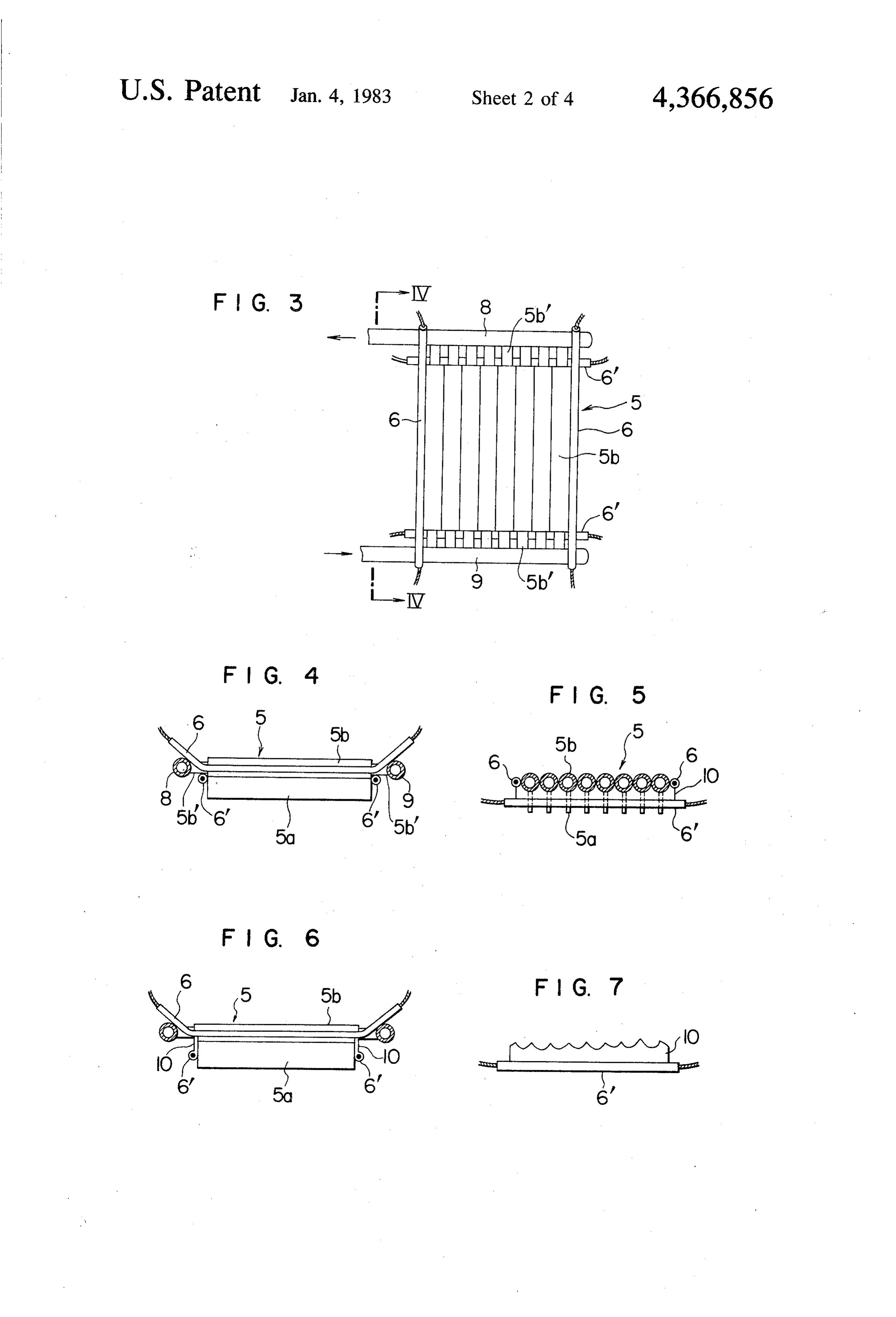
with a heat-storing material of the latent heat type, for FIG. 4 is a view along line IV-IV in FIG. 3 example, calcium chloride hexahydrate (CaCl2.6H2O, FIG. 5 is a cross-sectional front view of another em melting point 28°C.) and provided therein with a heat bodiment of a heat exchanger for cooling in the present exchanger for recovering heat or storing heat. For ex apparatus for storing heat.
ample, when the heat possessed by a heat-storing mate FIG. 6 is a side view of the apparatus shown in FIG. rial is recovered to heat rooms, the liquid heat-storing 20 5.
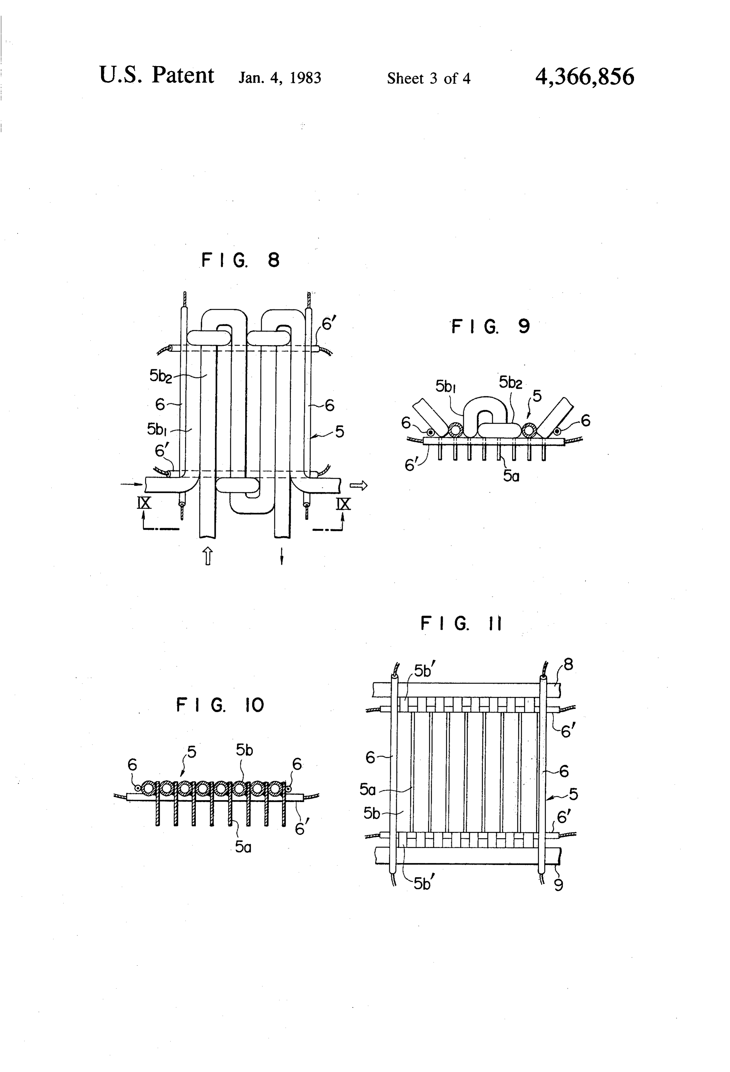
material reaches the solification point, and crystals of FIG. 7 is a front view of the essential part of the heat the heat-storing material deposit on the periphery of the exchanger for cooling as shown in FIGS. 5 and 6. heat exchanger. Resistance to heat transfer increases FIG. 8 is a plan view of further embodiment of a heat with increasing thickness of deposited crystal layer, and exchanger for cooling.
a heat exchange capacity is considerably reduced. 25
FIG. 9 is a view along line IX-IX in FIG. 8.
To prevent such a reduction, the flow of the heat FIG. 10 is a cross-sectional front view of further transfer medium through the heat transfer exchanger is embodiment of a heat exchanger for cooling. occasionally discontinued, or a heat transfer medium of FIG. 11 is a plan view of the heat exchanger shown in a higher temperature is occasionally passed through the FIG.
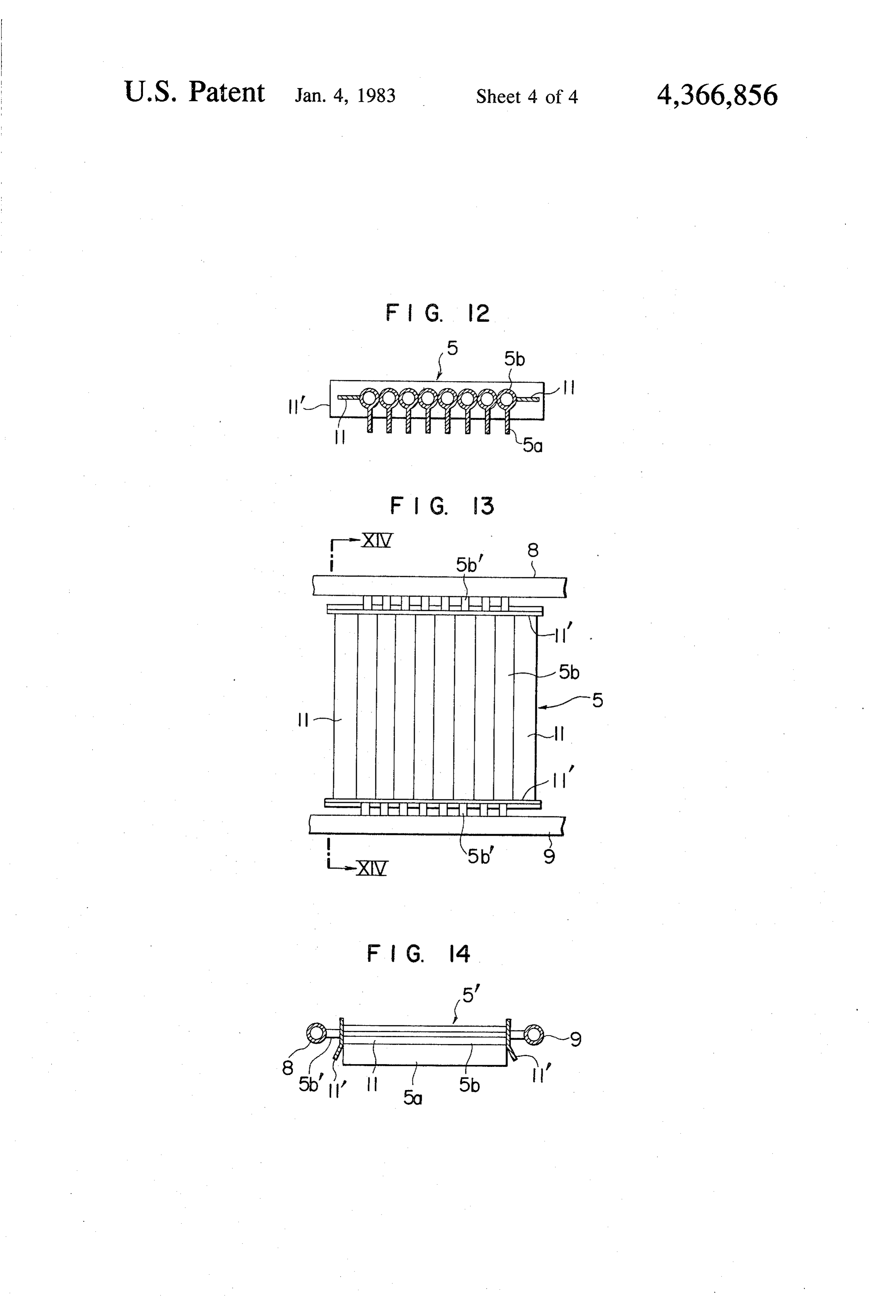
heat exchanger to release the deposited crystals of heat- 30 FIG.O.12 is a cross-sectional view of a heat exchanger storing material. However, the deposited crystals of for cooling in further embodiment of an apparatus for heat-storing material melt concentrically around the heat exchanger even according to the above-mentioned storing heat according to the present invention. procedure, and thus are very hard to release from the FIG, 12.13 is a plan view of the heat exchanger shown in FIG.
periphery of heat exchanger. 35
FIG. 14 is a cross-sectional view along line
To solve the problem, flange-like partition plates are XIV.-XIV provided at appropriate positions along the entire in FIG 3.
length of the pipe of heat exchanger to partition the PREFERRED EMBODIMENTS OF THE longitudinal direction of the pipe, and radial fin-like INVENTION partition plates are provided along the entire length of 40 the pipe of heat exchanger to partition the peripheral One embodiment of an apparatus for storing heat direction of the pipe, thereby allowing the deposited according to the present invention will be described crystals of heat-storing material to be readily released in below, referring to FIGS. 1-4.
a divided manner from the pipe. However, according to A vessel 1 for storing heat is filled with a heat-storing such a structure, the crystals of heat-storing material 45 material 2 of the latent heat type, for example, calcium released from the vessel for storing heat, and the space chloride hexahydrate (CaCl2.6H2O, melting point 28 factor of the released crystals of heat-storing material is C.), and a heat exchanger 5 for cooling is immersed at a deteriorated thereby, and there remains inevitably some higher level in the heat-storing material 2 in the vessel 1. effectively less utilizable liquid heat-storing material, The heat exchanger 5 comprises a group of a plurality necessitating use of an apparatus with a larger dimen- 50 of pipes 5b each with plate fins 5a at their bottoms, the sion. Since the partition plates must be provided along pipes being arranged horizontally in contact with one the entire length of the pipe, many partition plates, another at their sides, and heaters 6 at the outer periph particularly many fin-type partition plates, are required ery of the group of the pipes 5b as elements for releasing for the release. When a heat-storing material having a deposited crystals 3 of heat-storing material. relatively small heat conductivity such as calcium chlo 55 A heat exchanger 7 for heating is immersed at a lower ride hexahydrate is used, that is, when a heat-storing level in the heat-storing material 7 of latent heat type in material with a higher fin efficiency is used, the crystals the vessel 1 for storing heat. The heat exchanger 7 for of heat-storing material will deposit on the entire sur heating is used for heating and melting the crystals 3 of faces of the pipes and the partition plates, but the depos heat-storing material, and solar energy, waste heat, etc. ited crystals of heat-storing material melt only around 60 can be used as heat source for the heat exchanger 7. the heat exchanger and cannot be released therefrom in FIG.3 shows detail of the heat exchanger 5 and FIG. a divided manner, even if it is tried to release the depos 4 is a side view of the heat exchanger along line IV-IV ited crystals of heat-storing material. in FIG. 3. The individual pipes 5b are all connected to an inlet manifold 8 and an outlet manifold 9 for a heat
SUMMARY OF THE INVENTION 65 transfer medium through smaller pipes 5b'. Heaters 6 An object of the present invention is to provide an are provided horizontally in contact with the outer apparatus for storing heat, which can readily release periphery of the group of pipes 5b in the longitudinal crystals of heat-storing material deposited on the pe direction, and heaters 6 are also provided horizontally
Page 7
at ends of the group of pipes 5b at both sides in a direc in FIGS. A-4. According to such a structure, the tion perpendicular to the pipes 5b. Cord heaters can be amount of crystals 4 of heat-storing material growing inserted into the pipes 5b as heaters 6 and 6'. between the heaters 6' and the pipes 5b can be made as Recovery of the heat possessed by the heat-storing small as possible, and even if the crystals grow, they can material in container 1 for storing heat and utilization of 5 be melted as rapidly as possible. the recovered heat in room heating will be described FIGS. 8 and 9 show a further embodiment of hea below according to the apparatus for storing heat with exchanger 5 according to the present invention, where the above-mentioned structure. two pipes 5b1 and Sb2 are provided in a zigzag structure When a heat transfer medium of lower temperature is by means of vertical U bends and horizontal U bends, passed through the pipes 5b of heat exchanger 5, the 10 respectively, so that they can be horizontally in contact liquid heat-storing material 2 releases the heat of solidi with each other. According to such a structure, the fication and turns solid. The heat of solidification is manifolds 8 and 9 and smaller pipes 5b' of the heat ex transferred to the heat transfer medium in the pipes 5b, changer as shown in FIGS. 1-4 can be omitted. That is, and the stored heat is recovered, while crystals 3 of the structure can be made simpler.
heat-storing material deposit on the periphery of pipes 15 FIGS. 10 and 11 show a still further embodiment of 5b and fins 5a. The larger the thickness of the layer of heat exchanger 5 according to the present invention, deposited crystal 3 of heat-storing material, the larger where fins 5a and pipes 5b are separately fabricated, and the resistance to heat transfer. Thus, when the layer of the fins 5a are fixed to the sides of the pipes 5b by weld deposited crystals 3 has some thickness, a switch valve -ing, etc. According to such a structure, pipes with fins (not shown in the drawings) is changed to discontinue can be readily fabricated.
flow of the heat transfer medium of lower temperature FIGS. 12-14 show a still further embodiment of heat and pass a heat transfer medium of higher temperature exchanger 5 according to the present invention, where through the pipes 5b. For example, when the heat ex releasing plates 11 and 11" of poor thermal conductor changer is used as an evaporator for room heating in a such as fluorocarbon resin, etc. are provided as ele refrigeration cycle of air conditioner, a switch valve of 25 ments for releasing the crystals 3 of heat-storing mate refrigeration cycle is changed to pass a heat transfer rial in place of the heaters 6 of FIGS. 1-4. According to medium of higher temperature from a compressor to the such a structure, it is not necessary to pass electric cur heat exchanger 5. At the same time, the heaters 6 and 6' rent through the heaters to release the deposited crys are turned on. Among the deposited crystals 3 of heat tals 3 of heat-storing material, and the electric consump storing material on the periphery of pipes 5b and fins 5a 30 tion can be saved thereby. As can be seen from the of heat exchanger 5, those in contact with the periphery drawings, the plates 1 project horizontally from oppo of pipes 5b and fins 5a and heaters 6 and 6' then start to site sides of the exchanger 5 between vertically disposed melt. plates 11". Additionally, FIG. 14 shows that a free edge Generally, inorganic hydrated salts as a heat-storing of the plates 11", which extends across the ends of pipes material of latent heat type have a larger specific grav 35 5b, is angled outwardly away from them. ity in a solid state than in a liquid state. For example, In all the foregoing embodiments, fins 5a are fixed to calcium chloride hexahydrate (CaCl2.6H2O) has the pipes 5b, but the present invention can be effectively specific gravity of about 1.68 g/cm3 in a solid state, and carried out with pipes 5b without fins 5a. about 1.50 g/cm3 in a liquid state. Thus, the bottom In the foregoing description, the heat exchanger for masses 4 of crystals 3 of heat-storing material, i.e. the 40 cooling is provided at a higher level in the heat-storing masses at the bottom of heat exchanger 5, settle down at material in the vessel for storing heat, and the heat the bottom of the vessel for storing heat as a rectangular exchanger for heating is provided at a lower level, and mass, and accumulate regularly. Since the crystals 3 of the heat stored from the heat exchanger for heating is heat-storing material are removed from the periphery of recovered by the heat exchanger for cooling, and the pipes 5b and fins 5a, the resistance to heat transfer is 45 recovered heat is utilized in room heating operation. again decreased. That is, after a certain period of time However, the coldness stored from the heat exchanger from the start to recover the stored heat, the deposited for cooling can be recovered by the heat exchanger for crystals 3 of heat-storing material are made to be re heating on the contrary, and the recovered coldness can leased from the periphery of pipe 5b and fins 5a in the be utilized in room cooling operation. Even in the latter above-mentioned manner, whereby a considerable in 50 case, there is no change in the releasing action of the crease in the resistance to heat transfer can be pre deposited crystals of heat-storing material. vented. In the foregoing embodiments, the heat-storing mate When an appropriate amount of the crystals 4 of rial having a higher specific gravity in a crystal state heat-storing material released from the heat exchanger 5 than in a liquid state, for example, calcium chloride is accumulated at the bottom of the vessel 1 for storing 55 hexahydrate (CaCl2.6H2O) is used, but when coldness is heat, a fluid heated by the solar energy or waste heat is stored for room cooling, using a heat-storing material made to pass through the heat exchanger 7 for heating having a lower specific gravity in a crystal state than in at the bottom of the vessel 1 for storing heat, whereby a liquid state, for example, water, is used, a heat ex the crystals 4 of heat-storing material are heated and changer for cooling is provided at a lower level in the melted, and the heat is stored again in the liquid heat 60 heat-storing material and a heat exchanger for heating storing material 2. The foregoing operations are to be at a higher level in the heat-storing material. Even if a repeated. heat-storing material having a high heat conductivity FIGS. 5-7 show another embodiment of heat ex such as water is used, the deposited crystals of heat-stor changer, where partition plates 10 having a rugged edge ing material on the periphery of heat exchanger can be are fixed to heaters 6' provided perpendicularly to the 65 also readily released in a divided manner. pipes 5b at both ends of the pipes 5b so that the partition As described above, the crystals of heat-storing mate plates 0 can be engaged with the pipes 5b. Other mem rial can be readily and regularly formed as blocks and bers are the same as those of the heat exchangers shown the heat can be stored in a vessel for storing heat ac
Page 8
cording to the present invention, and thus the resistance 8. An apparatus according to claim 1 or 2 or 3 or 4 or to heat transfer at the heat exchanger can be reduced, 5 or 6, wherein the means for causing crystals of heat and the heat recovery from the heat-storing material storing material to release comprise a heating means. can be effectively carried out. That is, an apparatus for 9. Apparatus according to claim 8, wherein said heat storing heat can be made smaller in size. ing means comprises a first pair of heaters disposed What is claimed is: parallel to said pipes in contact with opposite sides of 1. Apparatus for storing heat of the type having a said group and a second pair of heaters disposed perpen heat exchanger for cooling immersed in a latent heat dicular 10.
to said pipes at opposite ends of said group.
Apparatus according to claim 9, wherein said type heat-storing material contained in a container for 10 second pair of heaters is disposed below said first pair of storing heat, wherein said heat exchanger comprises a heaters.
plurality of pipes horizontally arranged in contact with 11. Apparatus according to claim 10, wherein the each other at respective adjacent sides in a manner heaters of the second pair are provided with partition forming a group having the pipes all disposed on the plates extending toward the heaters of the first pair for same level within the container, and means for causing 15 restricting the amount of crystals growing between the crystals of heat-storing material deposited on the pe heaters.
riphery of the group of pipes to be released therefrom as 2. Apparatus according to claim 11, wherein the a first mass at an upper side of the group and as a second partition the pipes.
plates have a rugged edge for engaging against mass at a lower side of the group.
2. An apparatus according to claim 1, wherein a heat 20 5 or 13. Apparatus according to claim 1 or 2 or 3 or 4 or storing material having a higher specific gravity in a storing 6, wherein the means for causing crystals of heat crystal state than in a liquid state is used, and the heat arrangement material to release comprises a releasing plate exchanger for cooling is provided at a higher level in of poor thermal conductor. the heat-storing material.
14. An apparatus according to claim 13, wherein said 25 releasing plate arrangement comprises a first pair of 3. An apparatus according to claim 1, wherein a heat releasing plates disposed parallel to said pipes in contact storing material having a lower specific gravity in a with opposite sides of said group and a second pair of crystal state than in a liquid state is used, and the heat releasing plates disposed perpendicular to said first pair exchanger for cooling is provided at a lower level in the of pipes at opposite ends of said group. heat-storing material. 30 15. An apparatus according to claim 14, wherein the 4. Apparatus according to claim 1, wherein said plates of said first pair of releasing plates are horizon group of the pipes is provided with a plurality of fins, tally disposed.
each of said fins being associated with a respective one 16. An apparatus according to claim 15, wherein the of said pipes. plates of said second pair of plates are vertically dis 5. Apparatus according to claim 4, wherein each finis 35 posed in engagement with the ends of said pipes. 17. An apparatus according to claim 16, wherein a integrally formed so as to project from its associated free edge of each of the plates of the second pair, which pipe. extends across the group of pipes, is angled outwardly 6. Apparatus according to claim 4, wherein each fin is away from the respective end of the group of pipes. attached in contact with a side of its associated pipe. 40 18. An apparatus according to claim 17, wherein said 7. Apparatus according to claim 4 or 5 or 6, wherein first pair of plates extends between said second pair of said pins project vertically downwardly from said plates.
pipes. k s sk k
Provenance
- Collection
- Cited prior art
- Original PDF
- patentimages.storage.googleapis.com →
- Filed
- 1980-12-03
- Pages
- 8
- Method
- pdftotext (the PDF's own text layer) + pdftoppm 300dpi page scans
- Source
- Google Patents bibliographic record
- Granted
- 1983-01-04
- Inventors
- Michio Yanadori; Kohji Kamejima; Hideki Tanaka; Minoru Kano; Motokazu Uchida; Yoritsune Abe; Hitachi Ltd
- Transcribed from
- patentimages.storage.googleapis.com →