patent · US4339874
Method of making a wedge-shaped permanent magnet rotor assembly
20 July 1982
Page 1 — bibliographic record
United States Patent (19) 11) 4,339,874 McCarty et al. 45) Jul. 20, 1982 (54) METHOD OF MAKING AWEDGE-SHAPED 56) References Cited ' PERMANIENT MAGNET ROTOR ASSEMBLY U.S. PATENT DOCUMENTS 1,948,854 2/1934 Heath .................................. 310/156 75 Inventors: Frederick B. McCarty, San Pedro; 1,979,813 11/1934 Reis............. ... 310/156 Alexander Silver, Tarzana, both of 2,493,102 1/1950 Bruinard ..... ... 310/156 Calif. 2,719,931 10/1955 Kobev ............. ... 310/156 2,930,916 3/1960 Scanlon et al. ..... ... 310/156 irrinaa 8. 3,072,813 1/1963 Reijnst et al. ....... ... 310/156 (73) Assignee: The Garrett Corporation, Los 3,083,311 3/1963 Krasnow ............. ... 310/156 Angeles, Calif. 3,671,788, 6/1972 Knudson et al. .................... 310/156
(21) Appl. No.: 214,357 3,858,308 1/1975 Peterson ................................ 29/598 3,909,647 9/1975 Peterson. ... 310/156 4,117,360 9/1978 Richter ... ... 310/156
FOREIGN PATENT DOCUMENTS
Related U.S. Application Data
Primary Examiner-Carl E. Hall (62) Division of Ser. No. 973,346, Dec. 26, 1978, Pat. No. Attorney, Agent, or Firm-Fay I. Konzem; Albert J. 4,242,610. Miller 51 Int. Cl. ............................................. H02K 15/02 ABSTRACT (52) U.S.C. ...................................... 29/598; 310/42; A rotor assembly having self-locking wedge-shaped
310/153,261,262, 42, 43,218 6 Claims, 3 Drawing Figures
Page 2
Drawing sheet — no readable text.
Page 3
Drawing sheet — no readable text.
Page 4
METHOD OF MAKING AWEDGE-SHAPED
internal hub of non-magnetic material and proportioned
PERMANENT MAGNET ROTOR ASSEMBLY
such that it has little or no effect on the exciting flux.
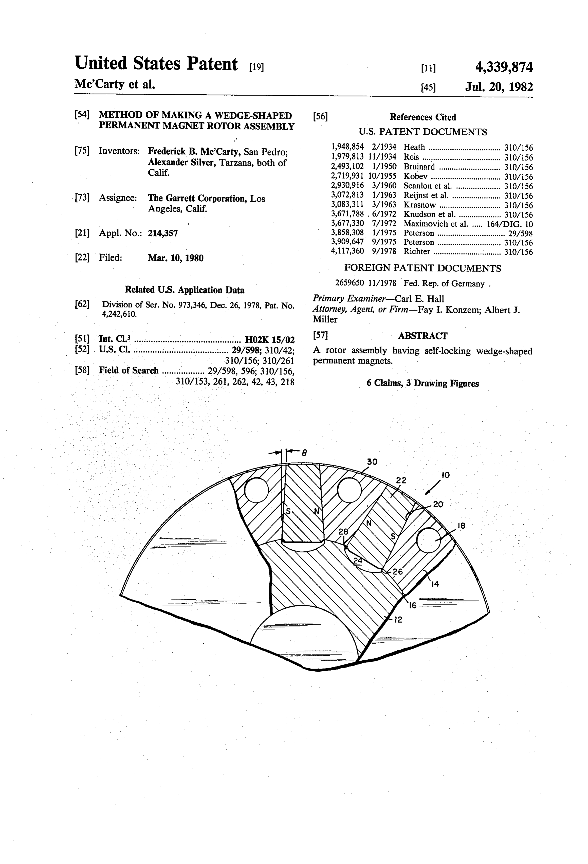
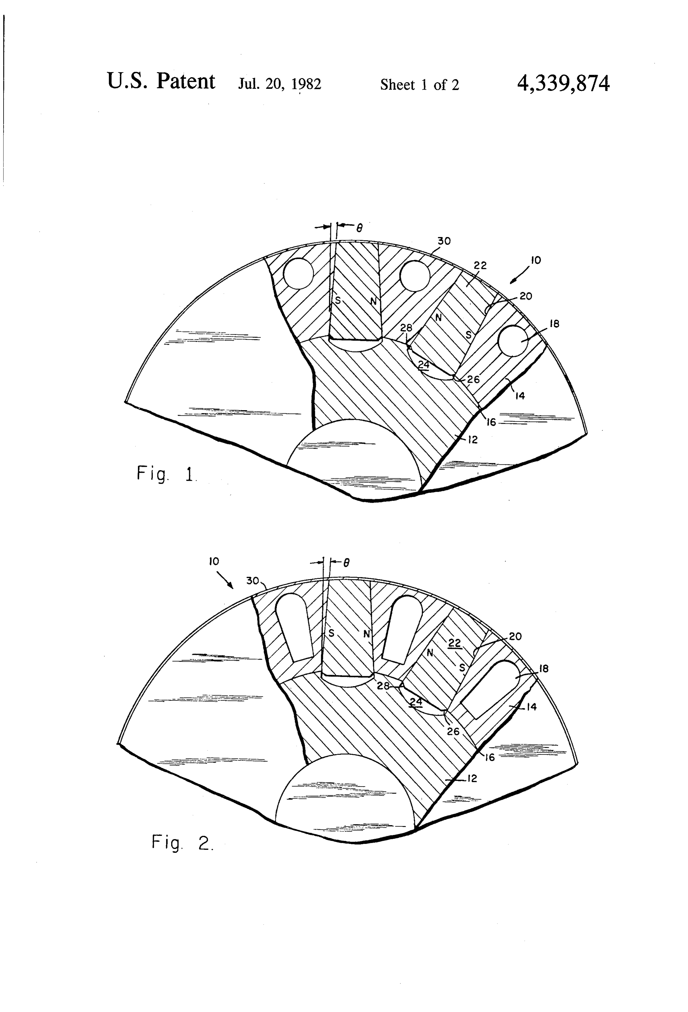
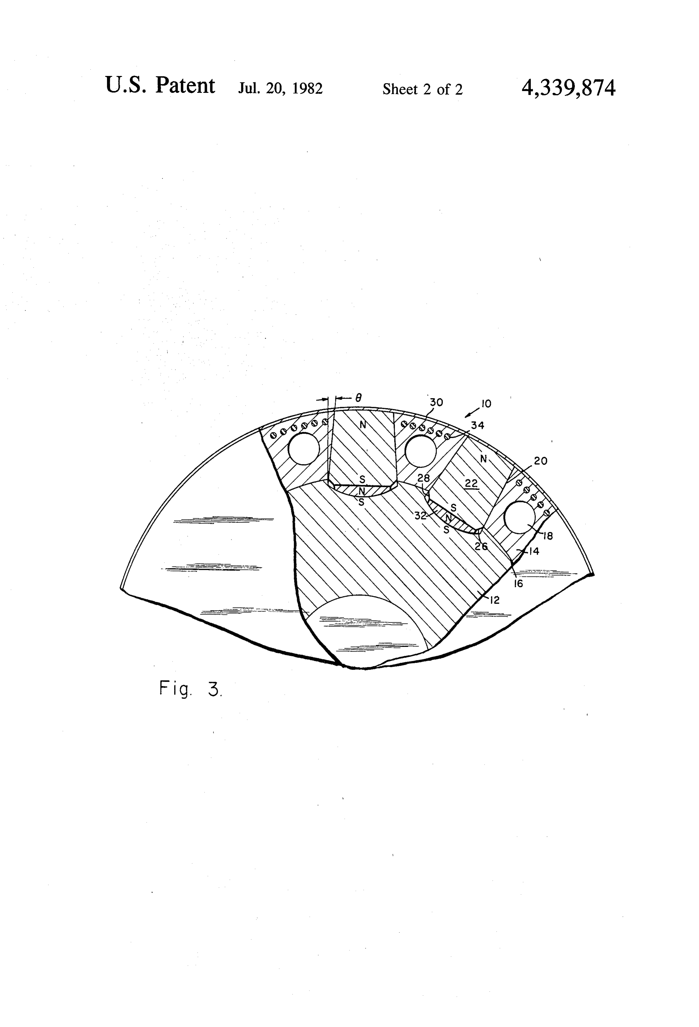
BRIEF DESCRIPTION OF THE DRAWINGS
This is a division of application Ser. No. 973,346 filed 5 FIG. 1 is a cross-section view of the rotor assembly of Dec. 26, 1978, now U.S. Pat. No. 4,242,610. the present invention with tangentially magnetized CROSS-REFERENCE TO RELATED magnets.
APPLICATIONS FIG. 2 shows a variance of the embodiment of FIG.
This invention relates to subject matter disclosed in 10 FIG. 3 is a cross-section view of the rotor assembly
1978, by Jerry Glaser, entitled "Rotor Assembly Hav DETAILED DESCRIPTION OF THE ing Anchors with Undulating Sides'; Ser. No. 973,344, PREFERRED EMBODIMENT filed Dec. 26, 1978, by Alexander Silver, entitled 15
"Rotor Assembly Having Rectangularly Shaped Referring now to FIGS. 1 and 2, a permanent magnet Tongues', now U.S. Pat. No. 4,260,921, and Ser. No. rotor assembly 10 includes a cylindrically shaped hub 973,343, filed Dec. 26, 1978, by Alexander Silver, Fred 12 which is surrounded by and affixed to support mem erick B. McCarty and Lyman R. Burgmeier, entitled bers 14. The hub 12 consists of a non-magnetic material "Rotor Assembly with Magnet Cushions', now U.S. and the support members 14 consist of a ferromagnetic Pat. No. 4,302,693, each of which are assigned to the 20 material when tangentially magnetized magnets are same assignee as this application. used. The hub 12 and the support members 14 are joined
BACKGROUND OF THE INVENTION
at the junction 16. A variety of conventional methods can be used to join the hub 12 and the support members
This invention relates to permanent magnet rotors 25 14; namely, furnace brazing the two materials together, and, more particularly, to wedge-shaped permanent using a cast bonding technique, diffusion bonding, or magnets in a rotor assembly for use in magnetic cou bonding by the hot isostatic pressure (HIP) process. plings, motors, and generators. The support members 14 have a plurality of generally A permanent magnet generator generally consists of equally spaced holes 18 disposed near the periphery a rotor including an even number of equally spaced, 30 thereof for reducing the rotor mass so that the rotor 10 alternating polarity magnets around the radial periph can operate at high speeds. The holes 18 can be of a ery and a stator which includes a number of windings variety of shapes, the circular shaped holes as shown in arranged to obtain magnetic couplings with the rotor FIG. 1 being the easiest to fabricate, whereas, the poles. Rotation of the rotor causes the flux linkage of oblong-shaped holes as shown in FIG. 2 are more diffi the permanent magnets with respect to the stator coils 35 in cult to fabricate into the support members 14 but result to vary, thus inducing an electromotive force in each of andlighter weight and a higher tip speed limit. The size location of the holes 18 is established with regard to the stator coils.
In the prior art, the rotor permanent magnets have magneticThe and structural considerations.
centrifugal stresses in the rotating rotor 10 are a been rectangularly shaped and supported against cen trifugal load by a hoop shrunk over the rotor's periph 40 function of radial dimensions, i.e. the centrifugal forces ery. The magnets have relatively poor tensile stress but get greater the farther out from the center of the rotor 10. Therefore, in order to reduce the stresses at critical fairly good compressive strength so they should be sections (such as at the bonded joint 16) mass is re compressively retained. In the case of high speed rotors, moved from the thickness of the magnet retaining hoop was greatly the pole bodythe14pole body 14 as near to the periphery of increased, disproportionate to other parts of the rotor, 45 turing considerations allow. structural, and manufac as magnetic, because self-stress of the hoop was large and little struc Besides allowing higher tip speed, the holes 18 permit tural capacity remained available to carry the magnets. cooling
Also, difficulties arose in uniformly distributing the dissipateairrotor flow through the pole body 14 and help to magnet load into the hoop, and this introduced bending Since the stator surfaceof a heat caused by eddy currents.
generator or motor is not a smooth stress concentrations into the hoop. Also, as the hoop 50 surface, but has iron teeth which cause ripple in the air thickness was increased, reluctance of the magnetic gap flux, eddy currents exist in the rotor surface and circuit increased and pole head leakage increased. cause heating. Excessive temperature is harmful to the SUMMARY OF THE INVENTION structural and magnetic properties of the rotor and magnets.
The permanent magnet rotor, in accordance with the 55 The support members 14 form a plurality of out invention, includes a rotatable hub with a plurality of wardly converging substantially wedge-shaped slots 20 inwardly converging wedge-shaped support members that are radially disposed about the hub 12. of magnetic material located around and affixed to the non-magnetic hub and outwardly converging wedge slots 20size The of the angle formed between the wall of the and a plane parallel to a central radius through shaped tangentially magnetized. permanent magnets 60 the which are radially located within the support members. anglemagnet is critical and should be slightly less than the of friction. This angle is experimentally deter
Advantages of the present invention are that the rotor mined and is the maximum angle at which a locking can rotate at a higher tip speed and also achieve better wedge action is achieved for the material and condi utilization of the magnet's field than the prior art rotors. tions pertinent to a given design. If the angle is too large The magnets are held in place in the support member by 65 the magnets will not remain locked in place after the their wedge-shape without a thick hoop intervening rotor ceases to rotate and if the angle is too small, lateral between the magnets and the stator. Structural reten crushing forces may cause the magnet to fracture. tion of magnets is provided by fusion bonding to an Therefore, there is a critical range within which the
Page 5
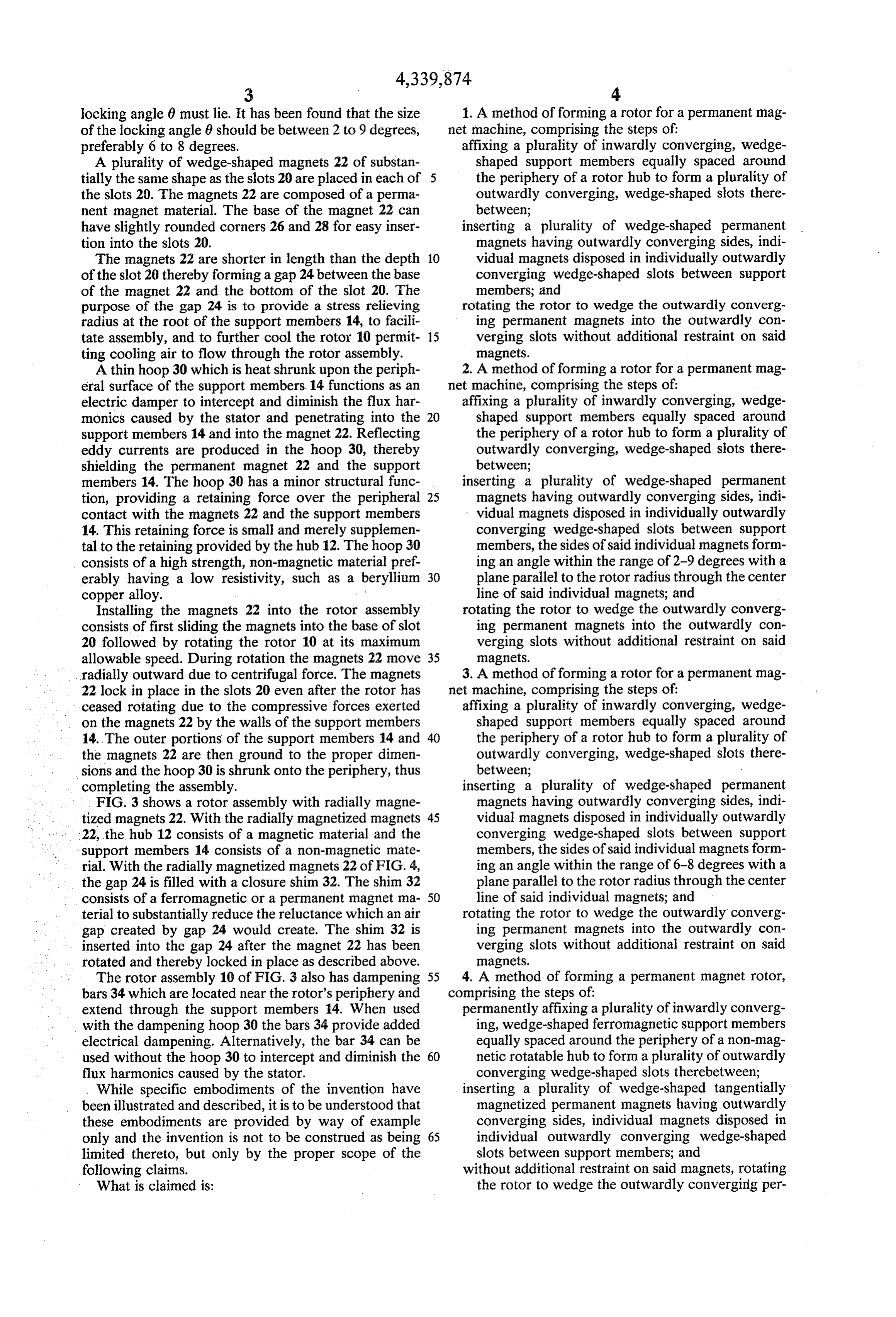
locking angle 6 must lie. It has been found that the size 1. A method of forming a rotor for a permanent mag of the locking angle 8 should be between 2 to 9 degrees, net machine, comprising the steps of: preferably 6 to 8 degrees. affixing a plurality of inwardly converging, wedge A plurality of wedge-shaped magnets 22 of substan shaped support members equally spaced around tially the same shape as the slots 20 are placed in each of 5 the periphery of a rotor hub to form a plurality of the slots 20. The magnets 22 are composed of a perma outwardly converging, wedge-shaped slots there nent magnet material. The base of the magnet 22 can between;
have slightly rounded corners 26 and 28 for easy inser inserting a plurality of wedge-shaped permanent tion into the slots 20. magnets having outwardly converging sides, indi The magnets 22 are shorter in length than the depth 10 vidual magnets disposed in individually outwardly of the slot 20 thereby forming a gap 24 between the base converging wedge-shaped slots between support of the magnet 22 and the bottom of the slot 20. The members; and purpose of the gap 24 is to provide a stress relieving rotating the rotor to wedge the outwardly converg radius at the root of the support members 14, to facili ing permanent magnets into the outwardly con tate assembly, and to further cool the rotor 10 permit 15 verging slots without additional restraint on said ting cooling air to flow through the rotor assembly. magnets.
A thin hoop 30 which is heat shrunk upon the periph 2. A method of forming a rotor for a permanent mag eral surface of the support members 14 functions as an net machine, comprising the steps of: electric damper to intercept and diminish the flux har affixing a plurality of inwardly converging, wedge monics caused by the stator and penetrating into the 20 shaped support members equally spaced around support members 14 and into the magnet 22. Reflecting the periphery of a rotor hub to form a plurality of eddy currents are produced in the hoop 30, thereby outwardly converging, wedge-shaped slots there shielding the permanent magnet 22 and the support between;
members 14. The hoop 30 has a minor structural func inserting a plurality of wedge-shaped permanent tion, providing a retaining force over the peripheral 25 magnets having outwardly converging sides, indi contact with the magnets 22 and the support members vidual magnets disposed in individually outwardly 14. This retaining force is small and merely supplemen converging wedge-shaped slots between support tal to the retaining provided by the hub 12. The hoop 30 members, the sides of said individual magnets form consists of a high strength, non-magnetic material pref ing an angle within the range of 2-9 degrees with a erably having a low resistivity, such as a beryllium 30 plane parallel to the rotor radius through the center copper alloy. line of said individual magnets; and Installing the magnets 22 into the rotor assembly rotating the rotor to wedge the outwardly converg consists of first sliding the magnets into the base of slot ing permanent magnets into the outwardly con 20 followed by rotating the rotor 10 at its maximum verging slots without additional restraint on said allowable speed. During rotation the magnets 22 move 35 magnets.
radially outward due to centrifugal force. The magnets 3. A method of forming a rotor for a permanent mag 22 lock in place in the slots 20 even after the rotor has net machine, comprising the steps of: ceased rotating due to the compressive forces exerted affixing a plurality of inwardly converging, wedge on the magnets 22 by the walls of the support members shaped support members equally spaced around 14. The outer portions of the support members 14 and 40 the periphery of a rotor hub to form a plurality of the magnets 22 are then ground to the proper dimen outwardly converging, wedge-shaped slots there sions and the hoop 30 is shrunk onto the periphery, thus between;
completing the assembly. inserting a plurality of wedge-shaped permanent FIG. 3 shows a rotor assembly with radially magne magnets having outwardly converging sides, indi tized magnets 22. With the radially magnetized magnets 45 vidual magnets disposed in individually outwardly 22, the hub 12 consists of a magnetic material and the converging wedge-shaped slots between support - support members 14 consists of a non-magnetic mate members, the sides of said individual magnets form rial. With the radially magnetized magnets 22 of FIG. 4, ing an angle within the range of 6-8 degrees with a the gap 24 is filled with a closure shim 32. The shim 32 plane parallel to the rotor radius through the center consists of a ferromagnetic or a permanent magnet ma 50 line of said individual magnets; and terial to substantially reduce the reluctance which an air rotating the rotor to wedge the outwardly converg gap created by gap 24 would create. The shim 32 is ing permanent magnets into the outwardly con inserted into the gap 24 after the magnet 22 has been verging slots without additional restraint on said rotated and thereby locked in place as described above. magnets.
The rotor assembly 10 of FIG.3 also has dampening 55 4. A method of forming a permanent magnet rotor, bars 34 which are located near the rotor's periphery and comprising the steps of:
extend through the support members 14. When used permanently affixing a plurality of inwardly converg with the dampening hoop 30 the bars 34 provide added ing, wedge-shaped ferromagnetic support members electrical dampening. Alternatively, the bar 34 can be equally spaced around the periphery of a non-mag used without the hoop 30 to intercept and diminish the 60 netic rotatable hub to form a plurality of outwardly flux harmonics caused by the stator. converging wedge-shaped slots therebetween; While specific embodiments of the invention have inserting a plurality of wedge-shaped tangentially been illustrated and described, it is to be understood that magnetized permanent magnets having outwardly these embodiments are provided by way of example converging sides, individual magnets disposed in only and the invention is not to be construed as being 65 individual outwardly converging wedge-shaped limited thereto, but only by the proper scope of the slots between support members; and following claims. without additional restraint on said magnets, rotating What is claimed is: the rotor to wedge the outwardly converging per
Page 6
manent magnets in place in the outwardly converg ing slots without excessive compressive force ap ing slots without excessive compressive force ap plied to the sides of said magnets. plied to the sides of said magnets. 6. A method of forming a permanent magnet rotor 5. A method of forming a permanent magnet rotor 5 comprising the steps of:
comprising the steps of: permanently affixing a plurality of inwardly converg permanently affixing a plurality of inwardly converg ing wedge-shaped ferromagnetic support members ing wedge-shaped ferromagnetic support members equally spaced around the periphery of non-mag equally spaced around the periphery of non-mag netic rotatable hub to form a plurality of outwardly converging wedge-shaped slots therebetween;
netic rotatable hub to form a plurality of outwardly 10 inserting a plurality of wedge-shaped tangentially converging wedge-shaped slots therebetween; magnetized permanent magnets having outwardly inserting a plurality of wedge-shaped tangentially converging sides, individual magnets disposed in magnetized permanent magnets having outwardly individual outwardly converging wedge-shaped converging sides, individual magnets disposed in slots between support members, the sides of said individual outwardly converging wedge-shaped 15 individual magnets forming an angle within the slots between support members, the sides of said range of 6-8 degrees with a plane parallel to the individual magnets forming an angle within the rotor radius through the center line of said individ range of 2-9 degrees with a plane parallel to the ual magnets; and rotor radius through the center line of said individ 20 without the additional restraint on said magnets, rotating rotor to wedge the outwardly converging per ual magnets; and manent magnets in place in the outwardly converg without additional restraint on said magnets, rotating ing slots without excessive compressive force ap the rotor to wedge the outwardly converging per plied to the sidessk ofis saidk magnets. manent magnets in place in the outwardly converg k sk
Provenance
- Collection
- Cited prior art
- Original PDF
- patentimages.storage.googleapis.com →
- Filed
- 1980-03-10
- Pages
- 6
- Method
- pdftotext (the PDF's own text layer) + pdftoppm 300dpi page scans
- Source
- Google Patents bibliographic record
- Granted
- 1982-07-20
- Inventors
- Frederick B. Mc'Carty; Alexander Silver; Garrett Corp
- Transcribed from
- patentimages.storage.googleapis.com →