patent · US3830667
Method of making flexible fiberoptic bundles
20 August 1974
Page 1 — bibliographic record
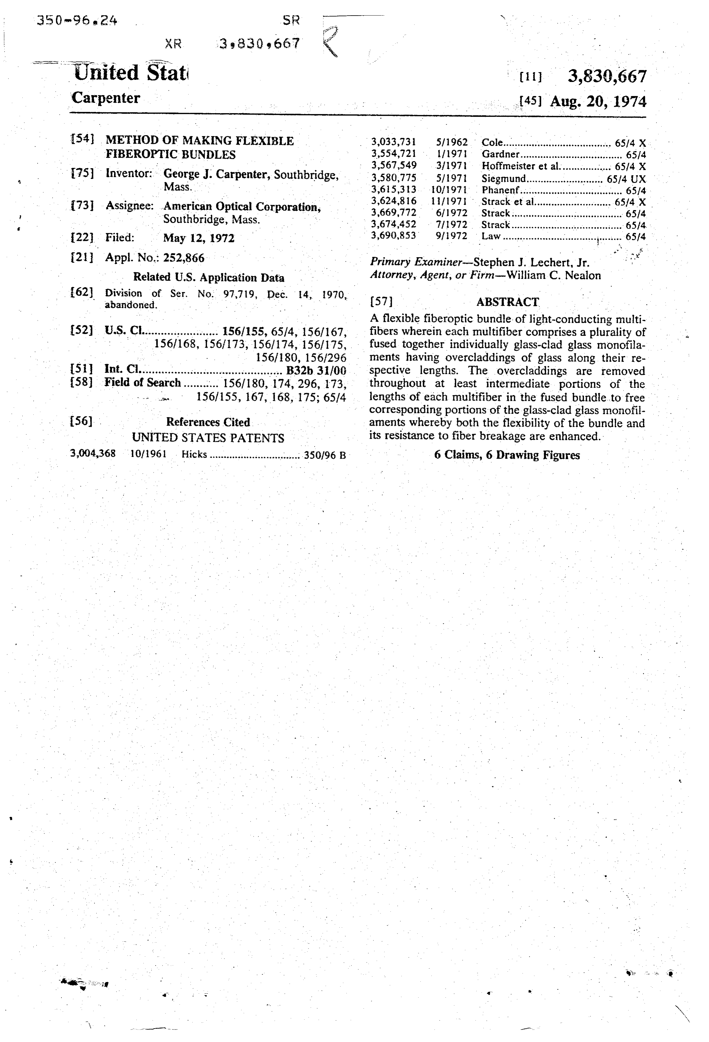
United Stat. (11) 3,830,667 Carpenter .. (45) Aug. 20, 1974 (54) METHOD OF MAKING FLEXIBLE 3,033,731 5/1962 Cole...................................... 6514 x FBEROPTIC BUNDLES 3,554,721 111971 Gardner.................................... 6514 : . . 3,567,549 3/1971 Hoffmeister et al....... ... 6.5/4 X 75) inventor: George J. Carpenter, Southbridge, 3,580,775 5/1971 Siegmund............... ... 65.14 UX Mass. 3,615,313 10/1971 Phanenf.................................... 6514 : R. . . 3,624,816 1971 . Strack et al........................... 65/4 X {73 Assignee: Southbridge,
American optical Corporation,
22 Fied: May 12, 1972 3,690,853 9, 1972 Law - - - - - - - - - - - - - - - - - - - - - -. . . . . . . . . . a 4 w: 65/4
(21) Appl. No. 252,866 Primary Examiner-Stephen J. Lechert, Jr. Related U.S. Application Data Attorney, Agent, or Firm-William C. Nealon (62) Ele." Ser. No. 97.719, Dec. 14, 1970, (57) ABSTRACT .. A flexible fiberoptic bundle of light-conducting multi 52 U.S. Cl........................ 1561155,6514, 156/167, fibers wherein each multifiber comprises a plurality of 156/168, 156/173, 1561174, 156/175, fused together individually glass-clad glass monofila 156/180, 156/296 ments having overcladdings of glass along their re (51 int. Cl............................................ B32b, 31/00 spective lengths. The overcladdings are removed 58) Field of Search........... 1561180, 174,296, 173, throughout at least intermediate portions of the 156/155, 167, 168, 175; 65/4 lengths of each multifiber in the fused bundle to free corresponding portions of the glass-clad glass monofil 56). References Cited aments whereby both the flexibility of the bundle and UNITED STATES PATENTS its resistance to fiber breakage are enhanced.
3,004,368 10/1961 Hicks.......................... ... 350/96 B 6 Claims, 6 Drawing Figures
. sy
Page 2
Drawing sheet — no readable text.
Page 3
Drawing sheet — no readable text.
Page 4
METHOD OF MAKENG FLEXIBLE FIBEROPTIC suitably flexible for the winding of endless ribbons is of BUNDLES Ser. No.97,719, filed . . exceptionally large cross-sectional size, e.g., greater.
This is a division, of application
Dec. 14, 1970, now abandoned. than 60 microns in thickness, so as to offer the impor tant advantage of easy and accurate side-by-side align
BACKGROUND OF THE INVENTION ment of convolutions thereof in the winding operation as well as exceptional ease in handling of the ribbons 1. Field of the invention -
Fiber optics with particular reference to flexible im in making the fiber bundle assembly as outlined herein
age-transmitting fiber bundles. The bundle, however, being relatively inflexible and 2. Description of the Prior Art O fragile at this stage, is prepared for leaching. Its oppo in dealing more particularly with the manufacture of site ends are coated with an acid-resistant plastic, wax flexible image-transmitting or coherent fiberoptic bun or dles, usually called "fiberscopes,' there is the long thethe like and the remaining intermediate portion of length of the bundle is exposed to a glass leaching standing need for easier and more economical fabrica medium, e.g., hydrochloric acid. The leaching medium, tion procedures, improvement in coherency (i.e., 15 in being free to circulate in between and around the image resolving capabilities of the finished bundle), multifibers, greater bundle strength and a reduction of the adverse dings of thereadily effects removal of the overclad monofilaments of each multifiber. This effect of fiber breakage upon image definition. greatly increases the flexibility of the fiberoptic bundle. - The foregoing has, to some extent, been accom and correspondingly reduces image degradation result plished by U.S. Pat. No. 3,033,731, but not entirely 20 ing from accidental breakage of individual loose fibers without problems. - in seeking greater coherency through better fiber image (monofilaments) of the bundle. Thus, large losses of alignment and bundle packing fraction it is necessary dividualdefinition which would ordinarily result from in multifiber fiber breakage are avoided.
to turn to the use of larger fibers which may, of course, While leached fiberoptic bundles per se, are known be multifibers. The use of larger fibers, however, ren 25 (e.g., as shown in U.S. Pat. No. 3,004,368) the fiber diers finished bundles less flexible and more susceptible to breakage. Adding to this, the breaking of a large aligning and packing techniques in such cases have not been entirely satisfactory, particularly when the result fiber (multifiber), leaves a correspondingly large void ing bundles are required to transport optical images. or non-transmitting area in the bundle. Thus, as fiber Furthermore, there has been a definite limitation as to size is increased, degradation of transmitted optical im 30 the thickness or cross-sectional size of a bundle which ages resulting from fiber breakage increases by an can be properly and efficiently leached to free its fibers' order of magnitude corresponding to the increase in without effecting damage thereto. This has been over
come
The present invention, in dealing with the manufac fiber bundles by the present invention wherein large format ture of flexible fiberoptic bundles, particularly of large leached to disconnect 35 of individually flexible multifibers are .
format, relates to matters of avoiding the aforemen ments of each multifiber.respective monofilament ele tioned problems of bundle fragility and optical image The invention will be more clearly understood by ref degradation resulting from fiber breakage by minimiz erence to the following detailed description when taken ing both. Greater than usual fiberalignment and bundle in conjunction with the accompanying drawing. packing fraction attended by improved bundle coher 40 ency and optical image resolution is achieved. DESCRIPTION OF THE DRAWINGS
SUMMARY OF THE INVENTION
The foregoing objectives are accomplished by utiliz multifiber
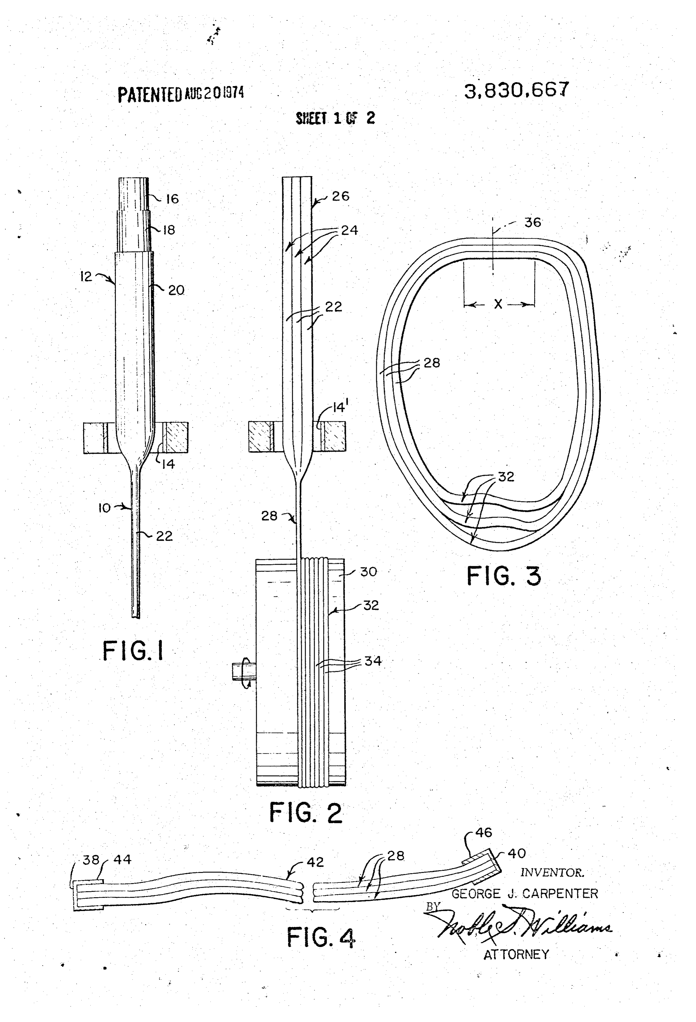
FIG. 1 diagrametically illustrates a proposed tech nique for making overclad glass-clad fiber from which ing, as much as possible, the flexible fiberoptic bundle 45 invention; may be produced according to the present manufacturing technique of U.S. Pat. No. 3,033,731 FIG. 2 diagrametically illustrates a technique for pro which obviates some of the earlier problems of fiber ducing an endless ribbon of a multifiber made up of a hand-packing and aligning operations. In this regard, a light-conducting fiber (multifiber) is wound upon a 50 plurality of the aforementioned overclad glass-clad glass fibers;
drum to form an endless ribbon of a width approxi FIG. 3 diagrametically illustrates an assembly of the mately equal to the width or lateral dimension desired endless multifiber ribbons from which a flexible bundle of the ultimate flexible fiber bundle. A number of rib may be formed;
bons, so formed, are stacked one over another through FIG. 4 illustrates the type of flexible fiber bundle re out a relatively short section of their respective lengths 55 sulting from cutting transversely through the assembly and cemented, fused or otherwise connected together. of FIG. 3, opposite ends of the bundle in this case are The assembly is then cut to form geometrically identi shown as having protective coverings thereover, cal opposite endfaces of the resulting flexible fiberoptic
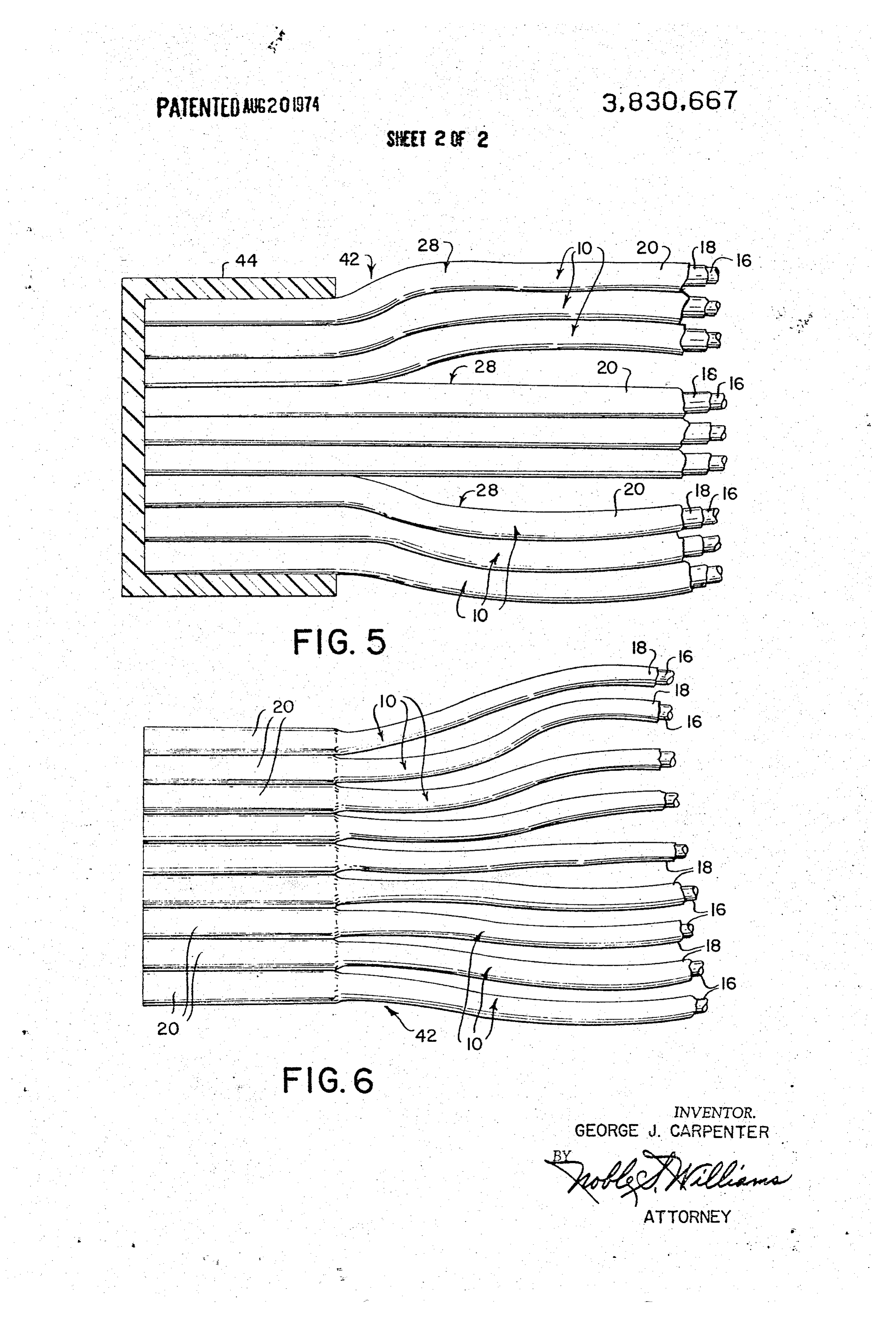
FIG. 5 is a greatly enlarged fragmentary, partially.
cross-sectioned elevational view of one end of the fiber in accordance with the present invention, however, bundle shown in FIG. 4; and the multifiber used to form each of the aforementioned 60 FIG. 6 is a similarly greatly enlarged elevational view endless fiber ribbons is comprised of a preselected of the same bundle following treatment thereof to en number of fused together light-conducting monofila hance the flexibility of the bundle and its resistance to . merits. Each monofilament has the usual high refractive breakage according to principles of the present inven index core, a lower refractive index first cladding and, 65 tion.
additionally, and overcladding of readily leachable, acid soluble glass. The latter is frequently referred to in DESCRIPTION OF PREFERREDEMBODIMENTS the trade as a "weathering" glass. The multifiber, being Referring more particularly to FIGS. 1-3, the opera
Page 5
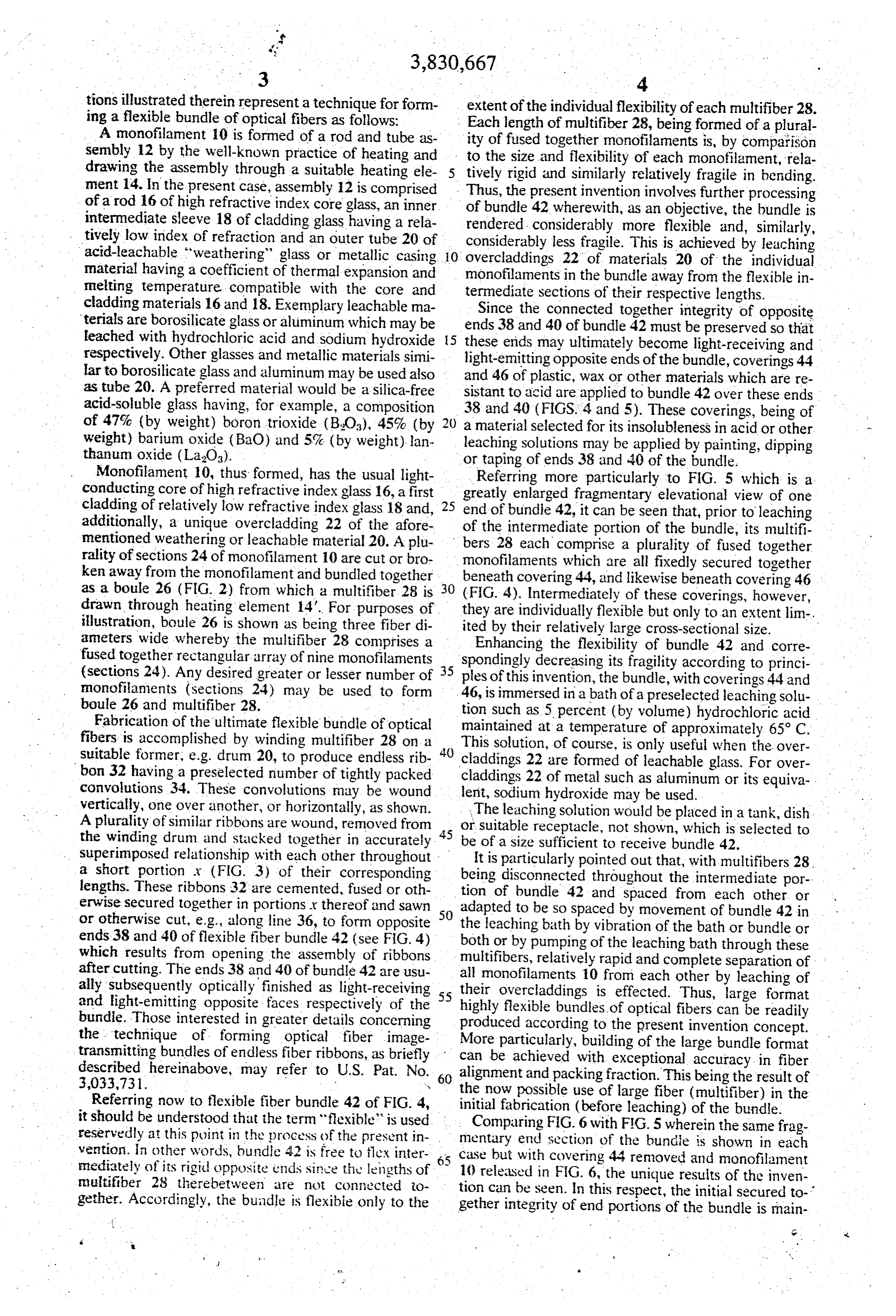
tions illustrated therein represent a technique for form extent of the individual flexibility of each multifiber 28. ing a flexible bundle of optical fibers as follows: . Each length of multifiber 28, being formed of a plural A monofilament 10 is formed of a rod and tube as ity of fused together monofilaments is, by comparison sembly 12 by the well-known practice of heating and to the size and flexibility of each monofilament, rela drawing the assembly through a suitable heating ele tively rigid and similarly relatively fragile in bending. ment 14. in the present case, assembly 12 is comprised Thus, the present invention involves further processing of a rod 16 of high refractive index core glass, an inner of bundle 42 wherewith, as an objective, the bundle is intermediate sleeve 18 of cladding glass having a rela rendered considerably more flexible and, similarly, tively low index of refraction and an outer tube 20 of considerably less fragile. This is achieved by leaching acid-leachable "weathering glass or metallic casing 10 overcladdings material having a coefficient of thermal expansion and monofilaments 22 of materials 20 of the individual melting temperature compatible with the core and termediate sections ofbundle in the their away from the flexible in respective lengths.
cladding materials 16 and 18. Exemplary leachable ma Since the connected together integrity of opposite terials are borosilicate glass or aluminum which may be ends 38 and 40 of bundle 42 must be preserved so that teached with hydrochloric acid and sodium hydroxide 5 these ends may ultimately become light-receiving and respectively. Other glasses and metallic materials simi light-emitting opposite ends of the bundle, coverings 44 lar to borosilicate glass and aluminum may be used also and 46 of plastic, wax or other materials which are re as tube 20. A preferred material would be a silica-free sistant to acid are applied to bundle 42 over these ends acid-soluble glass having, for example, a composition 38 and 40 (FIGS. 4 and 5). These coverings, being of of 47% (by weight) boron trioxide (BO), 45% (by a material selected for its insolubleness in acid or other weight) barium oxide (BaO) and 5% (by weight) lan leaching solutions may be applied by painting, dipping thanum oxide (LaO3). or taping of ends 38 and 40 of the bundle. Monofilament 10, thus formed, has the usual light Referring more particularly to FIG. 5 which is a conducting core of high refractive index glass 16, a first greatly enlarged fragmentary elevational view of one cladding of relatively low refractive index glass 18 and, 25 end of bundle 42, it can be seen that, prior to leaching additionally, a unique overcladding 22 of the afore of mentioned weathering or leachable material 20. A plu bersthe28intermediate portion of the bundle, its multifi each comprise a plurality of fused together rality of sections 24 of monofilament 10 are cut or bro monofilaments which are all fixedly secured together ken away from the monofilament and bundled together beneath covering 44, and likewise beneath covering 46 as a boule 26 (FIG. 2) from which a multifiber 28 is 30 (FIG. 4). Intermediately of these coverings, however, drawn through heating element 14'. For purposes of they are individually flexible but only to an extent lim-. illustration, boule 26 is shown as being three fiber di ited by their relatively large cross-sectional size. ameters wide whereby the multifiber 28 comprises a Enhancing the flexibility of bundle 42 and corre fused together rectangular, array of nine monofilaments spondingly decreasing its fragility according to princi (sections 24). Any desired greater or lesser number of 35 ples of this invention, the bundle, with coverings 44 and monofilaments (sections 24) may be used to form 46, is immersed in a bath of a preselected leaching solu boule 26 and multifiber 28. tion such as 5 percent (by volume) hydrochloric acid Fabrication of the ultimate flexible bundle of optical maintained at a temperature of approximately 65 C. fibers is accomplished by winding multifiber 28 on a This solution, of course, is only useful when the over suitable former, e.g. drum 20, to produce endless rib 40 claddings 22 are formed of leachable glass. For over bon 32 having a preselected number of tightly packed claddings 22 of metal such as aluminum or its equiva convolutions 34. These convolutions may be wound lent, sodium hydroxide may be used.
vertically, one over another, or horizontally, as shown.
A plurality of similar ribbons are wound, removed from 45 orThe leaching solution would be placed in a tank, dish the winding drum and stacked together in accurately be of a sizereceptacle, suitable not shown, which is selected to sufficient to receive bundle 42.
superimposed relationship with each other throughout It is particularly pointed out that, with multifibers 28. a short portion x (FIG. 3) of their corresponding being lengths. These ribbons 32 are cemented, fused or oth tion ofdisconnected bundle 42 throughout the intermediate por and spaced from each other, or erwise secured together in portions x thereof and sawn 50 adapted to be so spaced by movement of bundle 42 in or otherwise cut, e.g., along line 36, to form opposite the leaching bath by vibration of the bath or bundle or ends.38 and 40 of flexible fiber bundle 42 (see FIG. 4) both or by pumping of the leaching bath through these which results from opening the assembly of ribbons multifibers, relatively rapid and complete separation of after cutting. The ends 38 and 40 of bundle 42 are usu all monofilaments 10 from each other by leaching of ally subsequently optically finished as light-receiving 55 their overcladdings is effected. Thus, large format and light-emitting opposite faces respectively of the highly flexible bundles of optical fibers can be readily bundle. Those interested in greater details concerning produced according to the present invention concept. the technique of forming optical fiber image More particularly, building of the large bundle format transmitting bundles of endless fiber ribbons, as briefly can be achieved with exceptional accuracy in fiber described hereinabove, may refer to U.S. Pat. No. 60 alignment and packing fraction. This being the result of
Referring now to flexible fiber bundle 42 of FIG. 4, the now possible use of large fiber (multifiber) in the initial fabrication (before leaching) of the bundle.
it should be understood that the term “flexible' is used reservedly at this point in the process of the present in mentary end FIG.
Comparing 6 with FIG. 5 wherein the same frag vention. In other words, bundle 42 is free to flex inter 65 case but with coveringof44theremoved section bundle is shown in each and monofilament mediately of its rigid opposite ends since the lengths of 10 released in FIG. 6, the unique results multifiber 28 there between are not connected to tion can be seen. In this respect, the initialofsecured the inven
gether. Accordingly, the bundle is flexibie only to the gether integrity of end portions of the bundle is main
Page 6
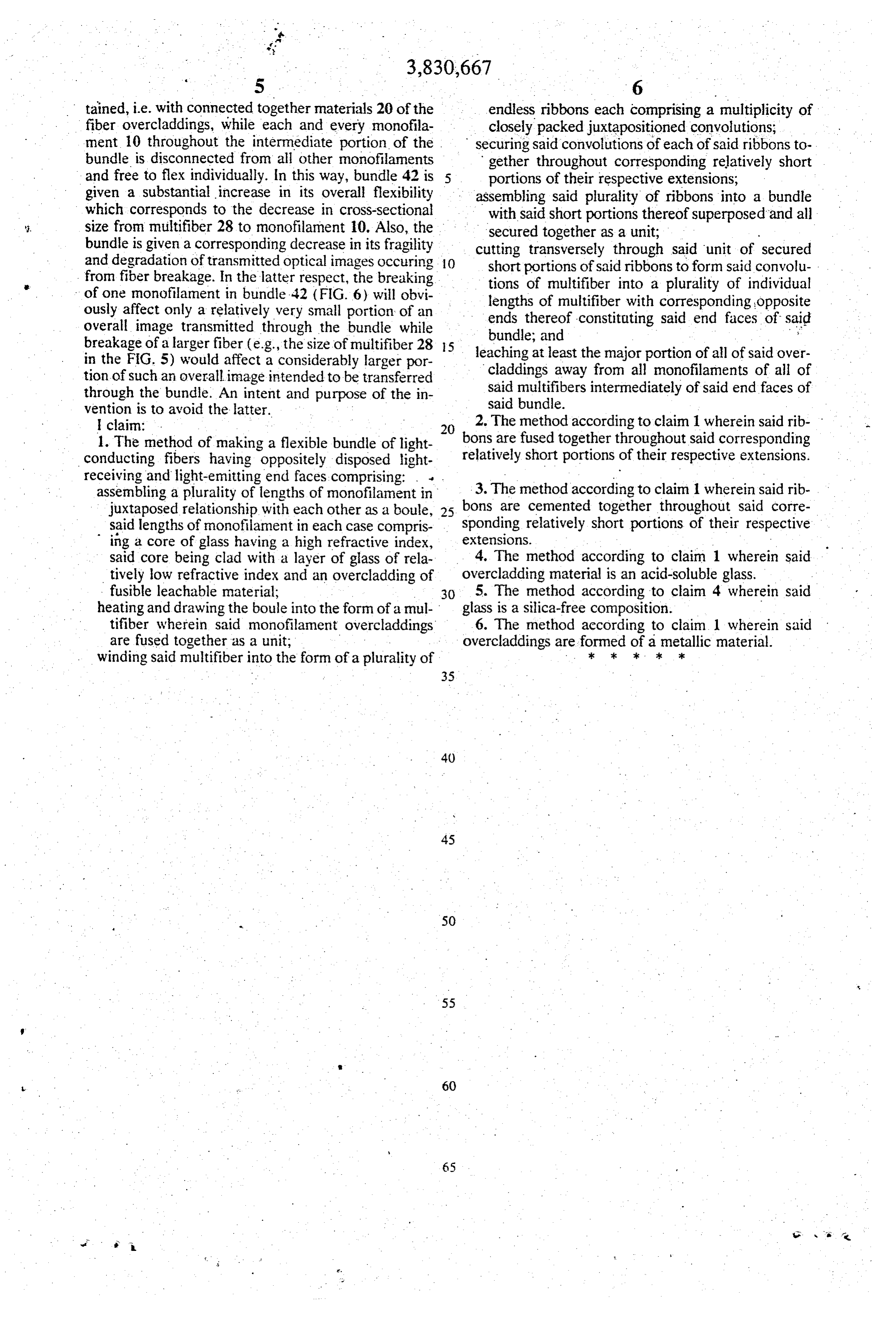
tained, i.e. with connected together materials 20 of the endless ribbons each comprising a multiplicity of fiber overcladdings, while each and every monofila closely packed juxtapositioned convolutions; ment 10 throughout the intermediate portion of the securing said convolutions of each of said ribbons to bundle is disconnected from all other monofilaments gether throughout corresponding relatively short and free to flex individually. In this way, bundle 42 is portions of their respective extensions; given a substantial increase in its overall flexibility assembling said plurality of ribbons into a bundle which corresponds to the decrease in cross-sectional with said short portions thereof superposed and all size from multifiber 28 to monofilament 10. Also, the secured together as a unit;
bundle is given a corresponding decrease in its fragility and degradation of transmitted optical images occuring O short portions of saidthrough cutting transversely ribbons said unit of secured to form said convolu from fiber breakage. In the latter respect, the breaking tions of multifiber into a plurality of individual of one monofilament in bundle. 42 (FIG. 6) will obvi lengths of multifiber with corresponding opposite ously affect only a relatively very small portion of an ends thereof constituting said end faces of said overall image transmitted through the bundle while bundle; and ; breakage of a larger fiber (e.g., the size of multifiber 28 5 leaching at least the major portion of all of said over in the FIG. 5) would affect a considerably larger por claddings away from all monofilaments of all of tion of such an overall image intended to be transferred said multifibers intermediately of said end faces of through the bundle. An intent and purpose of the in said bundle.
vention is to avoid the latter.
| claim: . . .. 2. The method according to claim 1 wherein said rib 1. The method of making a flexible bundle of light bons are fused together throughout said corresponding conducting fibers having oppositely disposed light relatively short portions of their respective extensions. receiving and light-emitting end faces comprising: . . .
assembling a plurality of lengths of monofilament in 3. The method according to claim 1 wherein said rib juxtaposed relationship with each other as a boule, 25. bons are cemented together throughout said corre sponding relatively short portions of their respective said lengths of monofilament in each case compris extensions.
ing a core of glass having a high refractive index, . said core being clad with a layer of glass of rela 4. The method according to claim 1 wherein said tively low refractive index and an overcladding of overcladding material is an acid-soluble glass. fusible leachable material; 30 5. The method according to claim 4 wherein said heating and drawing the boule into the form of a mul glass is a silica-free composition. - tifiber wherein said monofilament overcladdings 6. The method according to claim 1 wherein said are fused together as a unit, overcladdings are. . formed of. . a metallic material. winding said multifiber into the form of a plurality of k k . k.
Provenance
- Collection
- Cited prior art
- Original PDF
- patentimages.storage.googleapis.com →
- Filed
- 1972-05-12
- Pages
- 6
- Method
- pdftotext (the PDF's own text layer) + pdftoppm 300dpi page scans
- Source
- Google Patents bibliographic record
- Granted
- 1974-08-20
- Inventors
- G Carpenter; American Optical Corp
- Transcribed from
- patentimages.storage.googleapis.com →