patent · US4208363
Method of making a plurality of adjacent light pipe elements
17 June 1980
Page 1 — bibliographic record
United States Patent (19) (11) 4,208,363 Yevick (45) "Jun. 17, 1980 54) METHOD OF MAKING A PLURALITY OF (56) References Cited
ADJACENT LIGHT PIPE ELEMENTS
(75) Inventor: George J. Yevick, Leonia, N.J. 2,351,034 6/1944 Gabor ...................................... 264/1 3,043,910 7/1962 Hicks, Jr. ................................. 264/1 (73) Assignee: Izon Corporation, Stamford, Conn. 3,473,872 10/1969 Okamura ..... ... 350/96 B 3,718,515 2/1973 Goldstein ... ... 350/96 B * Notice: The portion of the term of this patent 3,728,422 4/1973 Sugaya ..................................... 264/ subsequent to Jan. 17, 1994, has been 3,839,514 10/1974 Nauta ....................................... 264/ disclaimed. 3,864,034 2/1975 Yevick ................................. 353/120 (21) Appl. No.: 719,008 Primary Examiner-James B. Lowe Attorney, Agent, or Firm-Thomas J. Greer, Jr.
22) Filed: Sep. 13, 1976 57 ABSTRACT A method of making a plurality of adjacent light pipe
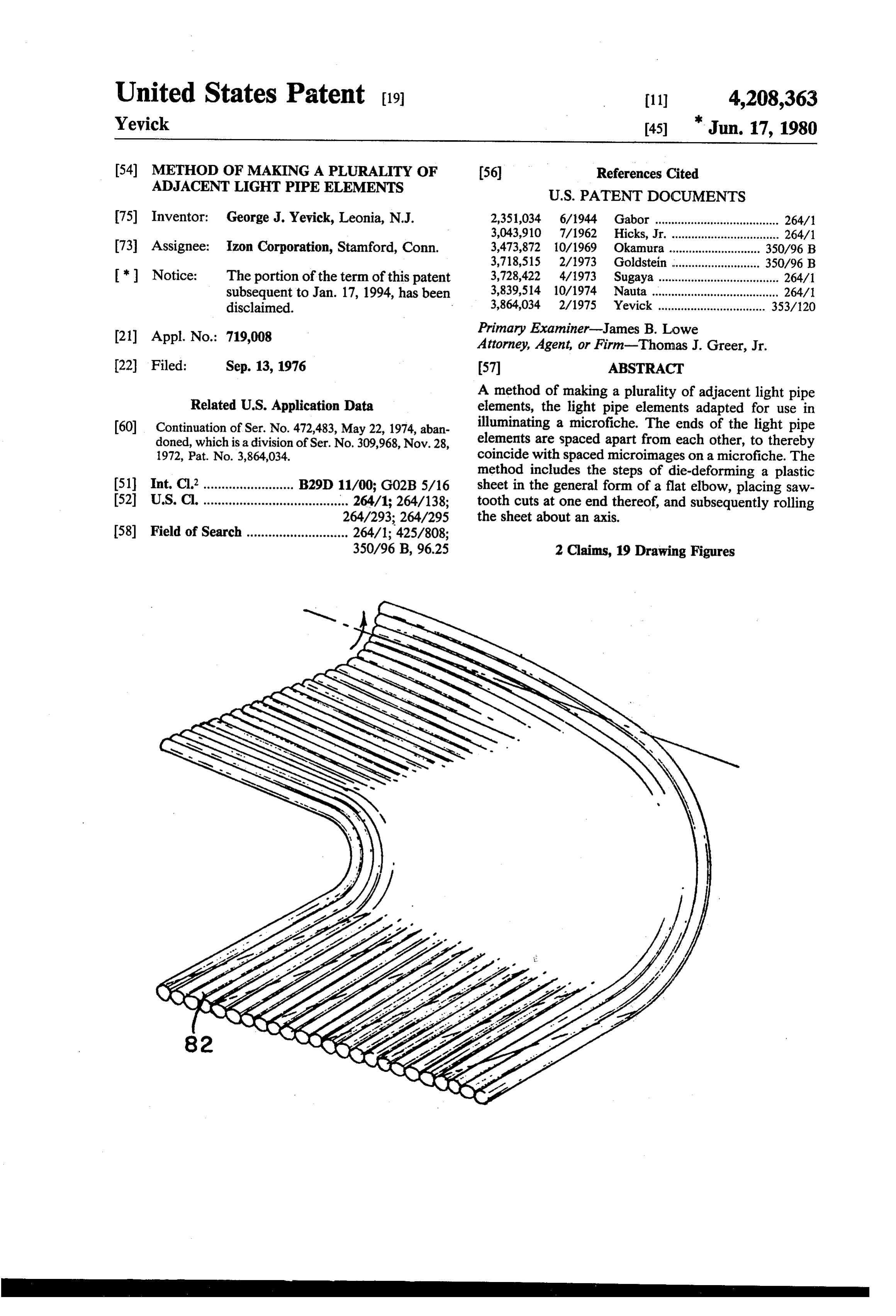
Related U.S. Application Data elements, the light pipe elements adapted for use in (60) Continuation of Ser. No. 472,483, May 22, 1974, aban illuminating a microfiche. The ends of the light pipe doned, which is a division of Ser. No. 309,968, Nov. 28, elements are spaced apart from each other, to thereby 1972, Pat. No. 3,864,034. coincide with spaced microimages on a microfiche. The method includes the steps of die-deforming a plastic (51) Int, Cl............... we a on B29D 11/00; G02B5/16 sheet in the general form of a flat elbow, placing saw (52) U.S. Cl. ........................................ 264/1; 264/138; tooth cuts at one end thereof, and subsequently rolling
(58) Field of Search ............................ 264/1; 425/808;
350/96 B, 96.25 2 Claims, 19 Drawing Figures
Page 2
Drawing sheet — no readable text.
Page 3
Drawing sheet — no readable text.
Page 4
Drawing sheet — no readable text.
Page 5
Drawing sheet — no readable text.
Page 6
Drawing sheet — no readable text.
Page 7
Drawing sheet — no readable text.
Page 8
Heat Absorbing Gloss Heat Absorbing Glass Porobotic
Condenser ens Mirrors Condenser Lens Reflecting Collinator Reflecting Collimotor Mirror F- FHO Y-Mirror Sheet A Contains 25x7O = Sheet B Contains 25x7O 750 Light Sources Ax = O.", 1750 Light Sources Ax=O."
Feed Roll For Sheet A Feed Rot For Sheet B
Page 9
Drawing sheet — no readable text.
Page 10
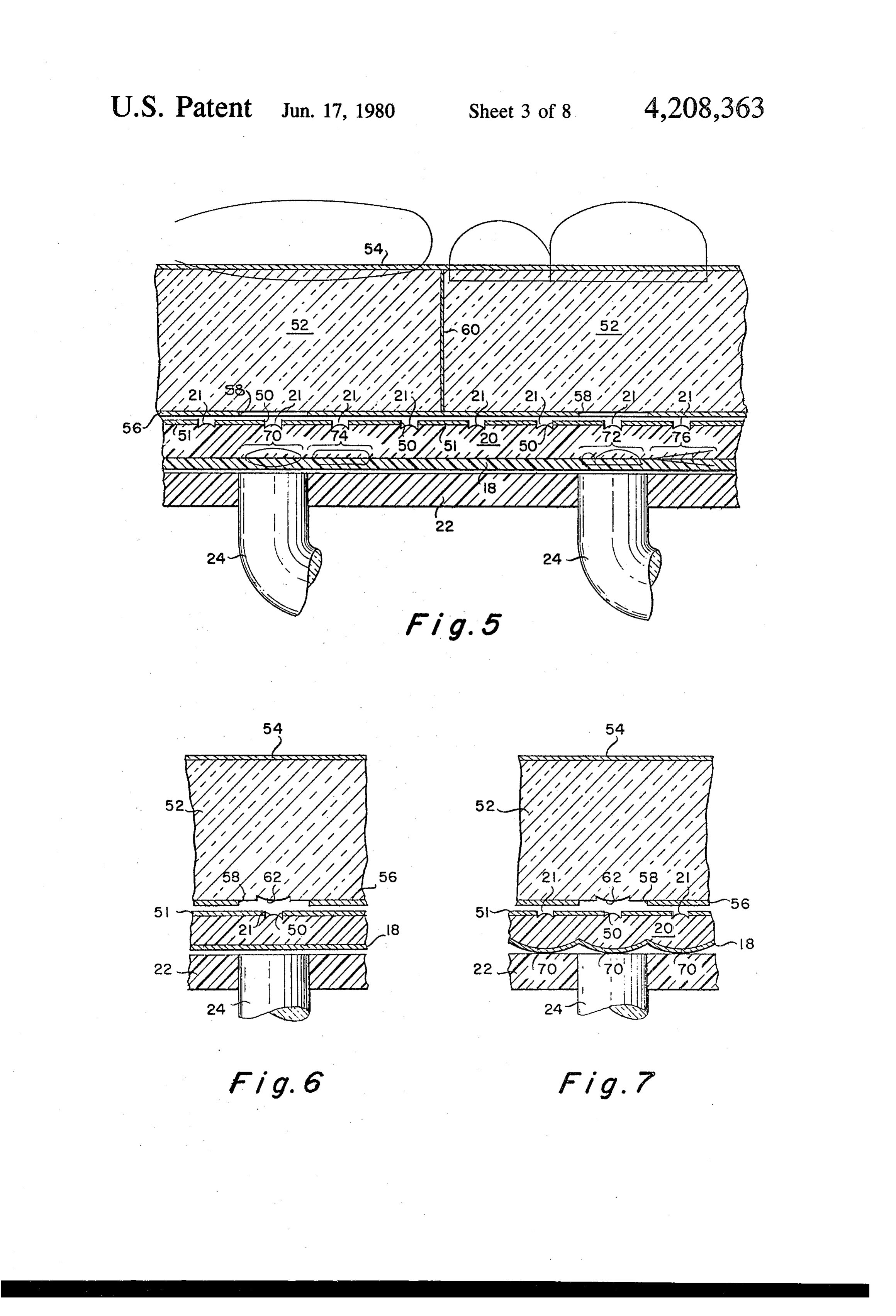
FIG. 6 is a partial view, similar to FIG. 5, and illus
METHOD OF MAKING A PLURALITY OF..., trates another embodiment.
ADJACENT LIGHT PIPE ELEMENTS FIG. 7 is a view, similar to FIG. 6, and illustrates an embodiment wherein the micro-images reside on Petz
This is a continuation of Ser. No. 472,483, filed May 5 val surfaces. . .
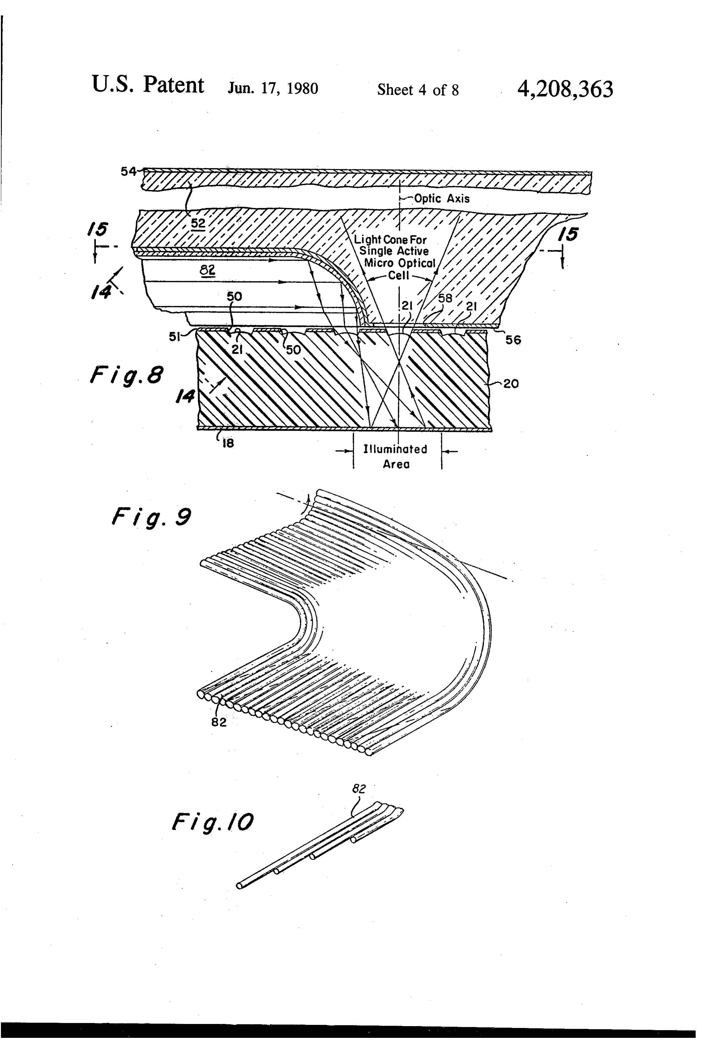
22, 1974 now abandoned, which was in turn a division FIG. 8 is a view, similar to FIG. 2, illustrating an of Ser. No. 309,968, filed No. 28, 1972 now U.S. Pat. embodiment wherein the micro-images carried by the No. 3,864,034 issued 2-4-75. fiche are illuminated for readout from the top or front. This invention relates to a method of making an il FIG. 9 is a perspective view of an illuminating de lumination device for illuminating microimages which 10 vice, and its manner of fabrication, used in the embodi are spaced apart from each other and are carried by the ment of FIG. 8.
emulsion of a microfiche. FIG. 10 is a partial view of FIG. 9, at a later stage in In certain prior constructions of micro-optic readers, formation.
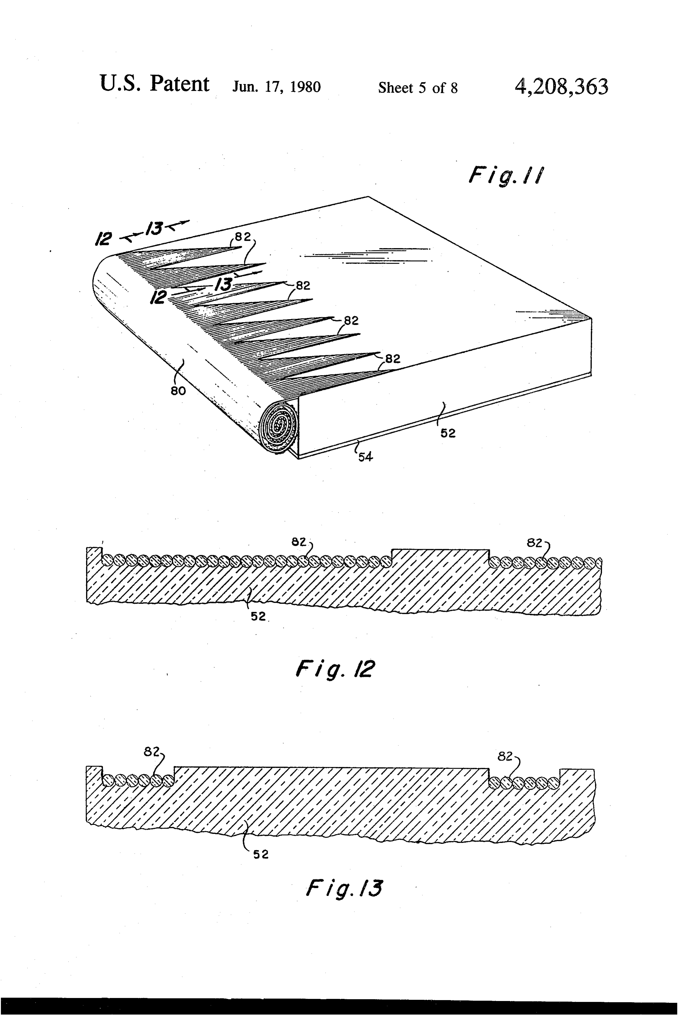
(such as described in copending application Ser. No. FIG. 11 is a perspective view of the front illuminating 135,996, filed Apr. 2, 1971 by Adnan Waly for "Micro 15 arrangement of FIG. 8.
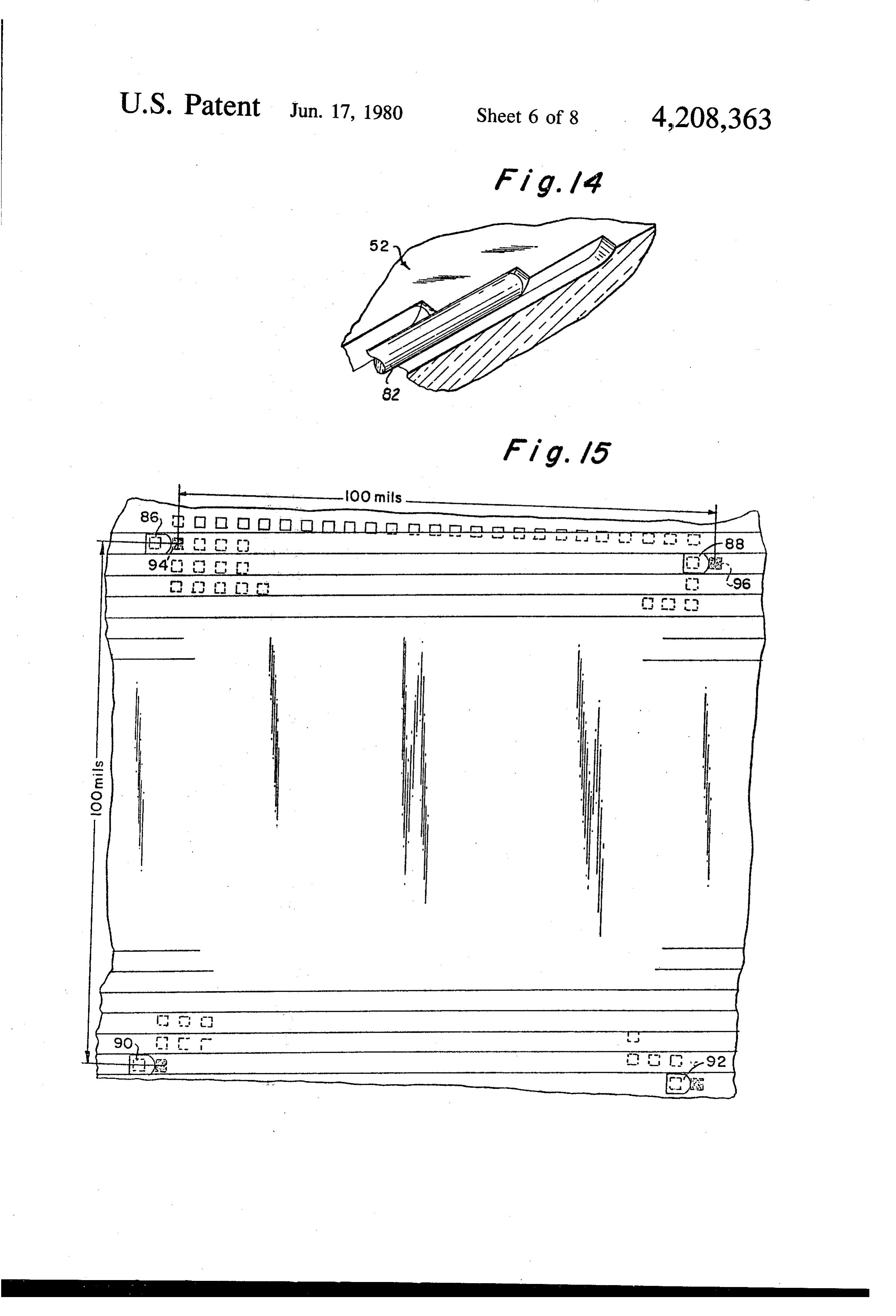
Image Recording and Read Out System,' and assigned FIG. 12 is a view along line 12-12 of FIG. 11. to the same assignee as this application, now U.S. Pat. FIG. 13 is a view along line 13-13 of FIG. 11. No. 3,704,068 of Nov. 28, 1972) a microfiche defined by FIG. 14 is a partial perspective view along line an emulsion film carried on one surface of a clear plastic 20 14-14 of FIG. 8 and illustrates the ends of the light sheet is positioned next to a plastic plate having discrete rods abutting channel ends in the viewing screen. optically active surfaces, i.e., lenses. An apertured mask FIG. 15 is a view taken along section 15-15 of FIG. may be employed, the mask inhibiting overlapping of 8.
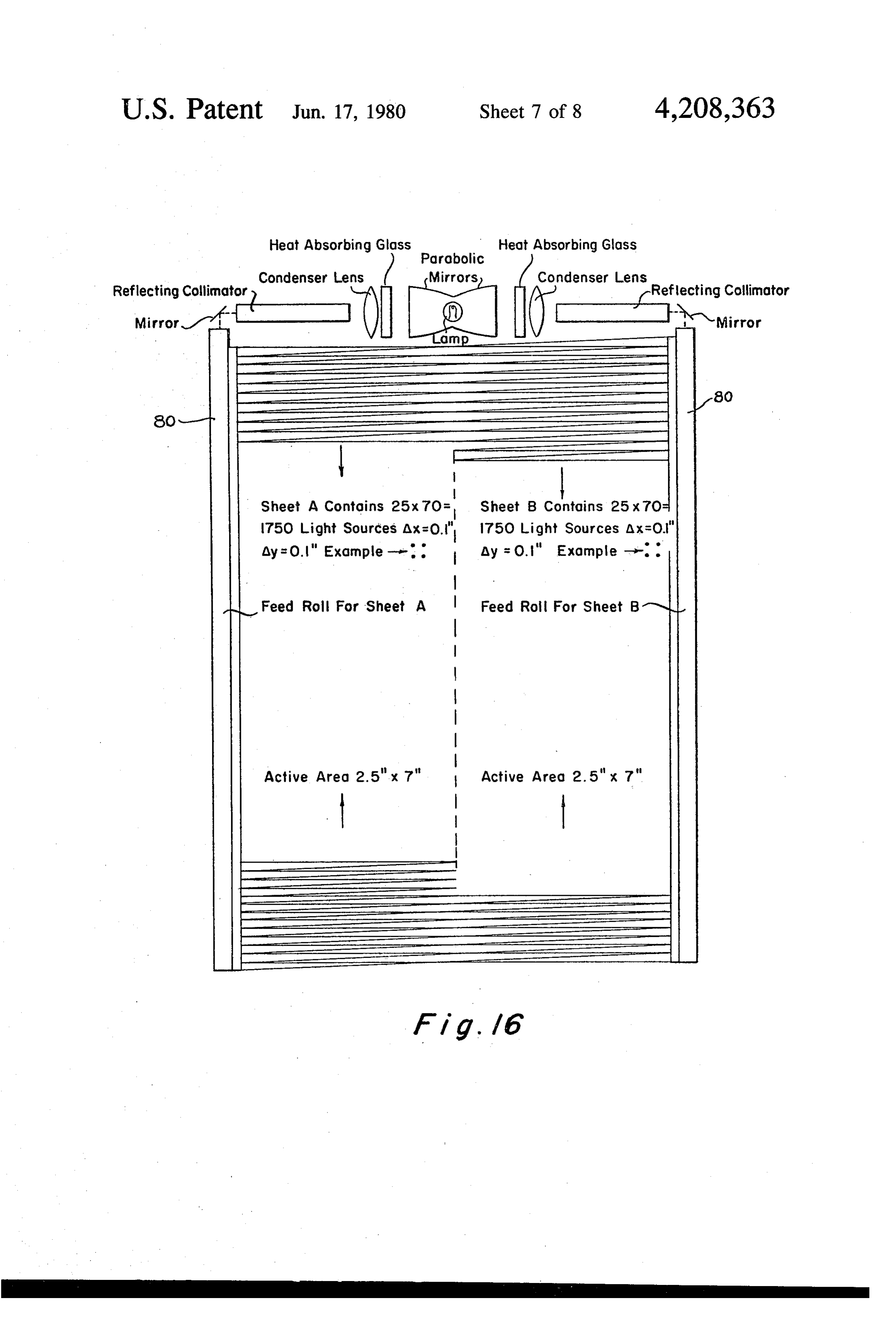
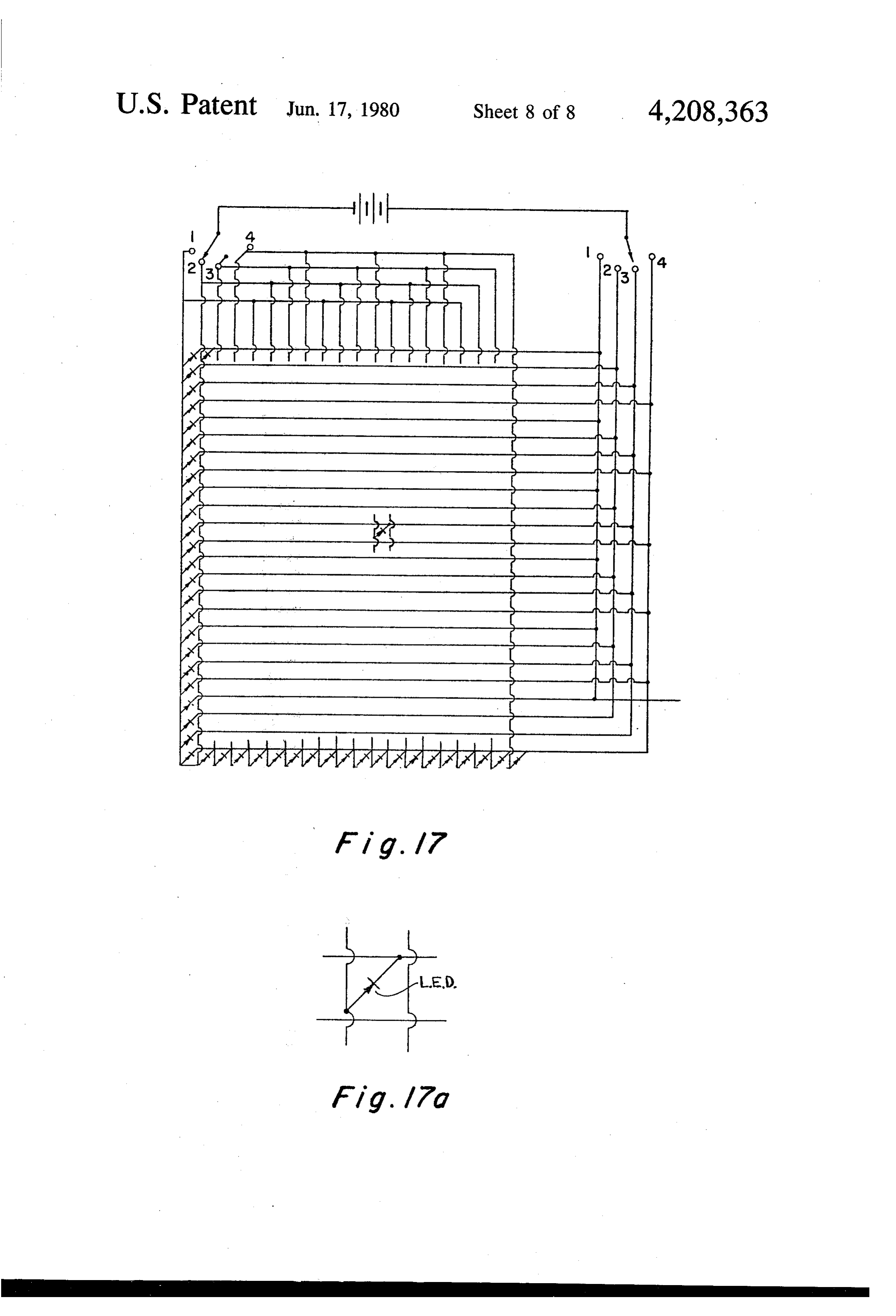
adjacent information. The proturberances function as FIG. 16 is a front view, partially schematic, of a lenses (termed lensettes because of their small size) and reader having a front illuminated fiche. FIGS. 17 and 17a are schematic views of a mode are intended to be aligned with optical bits of informa 25 employing tion on the microfiche emulsion, thereby projecting and a grid of light emitting diodes. magnifying the bits. In such constructions it is of para construction now
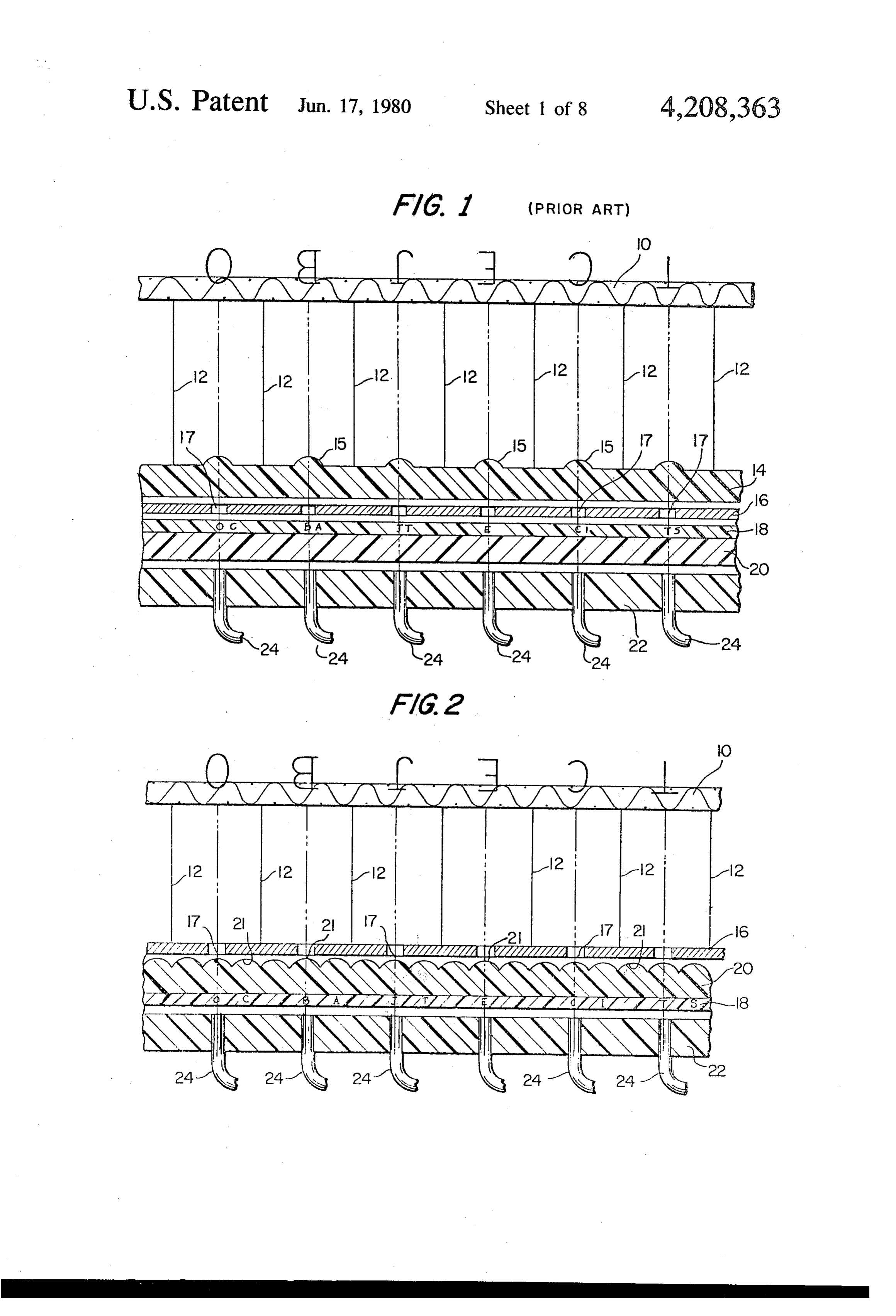
Referring to FIG. 1 of the drawings, a prior ar mount importance that the distance between the emul noted Waly patentmicroreader
sion and the lensettes remain constant during all readout 30 numeral 10 denotes a viewing screen illustrated. is schematically formed of,
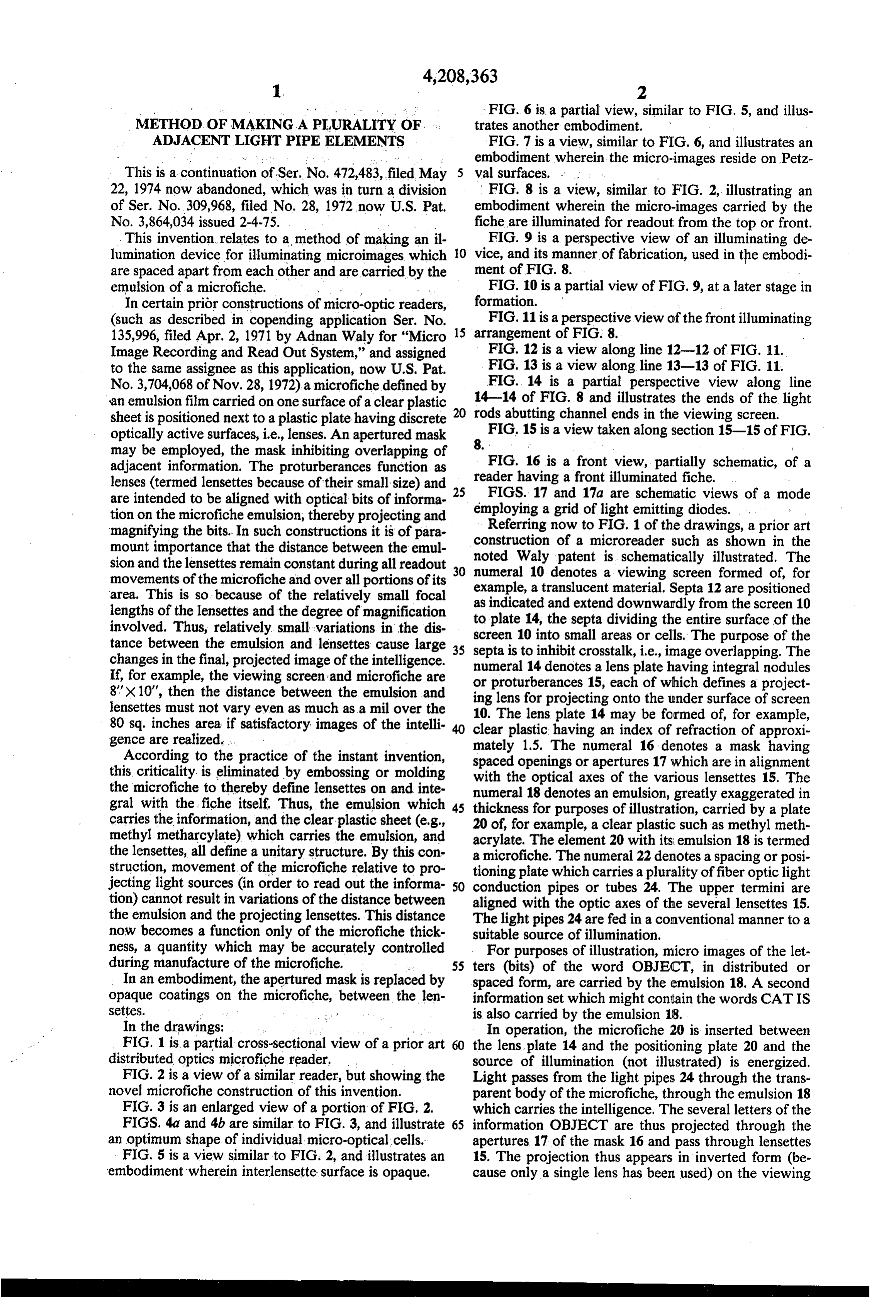
The for movements of the microfiche and over all portions of its example, a translucent material. Septa 12 are positioned area. This is so because of the relatively small focal as lengths of the lensettes and the degree of magnification to indicated plate 14, and extend downwardly from the screen 10 the septa dividing the entire surface of the involved. Thus, relatively small variations in the dis screen 10 into small areas or cells. The purpose of the tance between the emulsion and lensettes cause large 35 septa is to inhibit crosstalk, i.e., image overlapping. The changes in the final, projected image of the intelligence. numeral 14 denotes a lens plate having integral nodules If, for example, the viewing screen and microfiche are or proturberances 15, each of which 8' x 10', then the distance between the emulsion and ing lens for projecting onto the underdefines a project lensettes must not vary even as much as a mill over the 10. The lens plate 14 may be formed of, for of surface screen example, 80 sq. inches area if satisfactory images of the intelli clear plastic having an index of refraction of approxi gence are realized. mately 1.5. The numeral 16 denotes a mask having According to the practice of the instant invention, spaced this criticality, is eliminated by embossing or molding with theopenings optical or apertures 17 which are in alignment axes of the various lensettes. 15. The the microfiche to thereby define lensettes on and inte numeral 18 denotes an emulsion, greatly exaggerated in gral with the fiche itself. Thus, the emulsion which 45 thickness for purposes of illustration, carried by a plate carries the information, and the clear plastic sheet (e.g., 20 of, for example, a clear plastic such as methyl meth methyl metharcylate) which carries the emulsion, and acrylate. The element 20 with its emulsion 18 is termed the lensettes, all define a unitary structure. By this con a microfiche. The numeral 22 denotes a spacing or posi struction, movement of the microfiche relative to pro tioning plate which carries a plurality offiber optic light jecting light sources (in order to read out the informa 50 conduction pipes or tubes 24. The upper termini are tion) cannot result in variations of the distance between aligned with the optic axes of the several lensettes 15. the emulsion and the projecting lensettes. This distance The light pipes 24 are fed in a conventional manner to a now becomes a function only of the microfiche thick suitable source of illumination.
ness, a quantity which may be accurately controlled For purposes of illustration, micro images of the let during manufacture of the microfiche. 55 ters (bits) of the word OBJECT, in distributed or In an embodiment, the apertured mask is replaced by spaced form, are carried by the emulsion 18. A second opaque coatings on the microfiche, between the len information set which might contain the words CATIS Settes. is also carried by the emulsion 18. In the drawings: In operation, the microfiche 20 is inserted between FIG. 1 is a partial cross-sectional view of a prior art the lens plate 14 and the positioning plate 20 and the distributed optics microfiche reader, source of illumination (not illustrated) is energized. FIG. 2 is a view of a similar reader, but showing the Light passes from the light pipes 24 through the trans novel microfiche construction of this invention. parent body of the microfiche, through the emulsion 18 FIG. 3 is an enlarged view of a portion of FIG, 2. which carries the intelligence. The several letters of the FIGS. 4a and 4b are similar to FIG. 3, and illustrate 65 information OBJECT are thus projected through the an optimum shape of individual micro-optical cells. apertures 17 of the mask 16 and pass through lensettes FIG. 5 is a view similar to FIG. 2, and illustrates an 15. The projection thus appears in inverted form (be embodiment wherein interlensette surface is opaque. cause only a single lens has been used) on the viewing
Page 11
screen. In order to view the next segment, as for exam intelligence carried by the emulsion and their corre ple the next page, of information recorded on the micro sponding lens element 21. Further, if there is a slight fiche 20, the microfiche is moved to the left by an index inaccuracy in the embossing or molding process during ing mechanism, thereby aligning the letters (bits) of manufacture, the error is undone in the viewing or CAT IS with the openings 17. The letters of this second 5 readout because each lensette acts as a camera in the message will then appear on the viewing screen 10, as in taking process. Thus, lateral positioning of each optical the first case. bit (letter) with respect to the optic axis of each lensette Because of the relatively small focal lengths of the are no longer a critical factor.
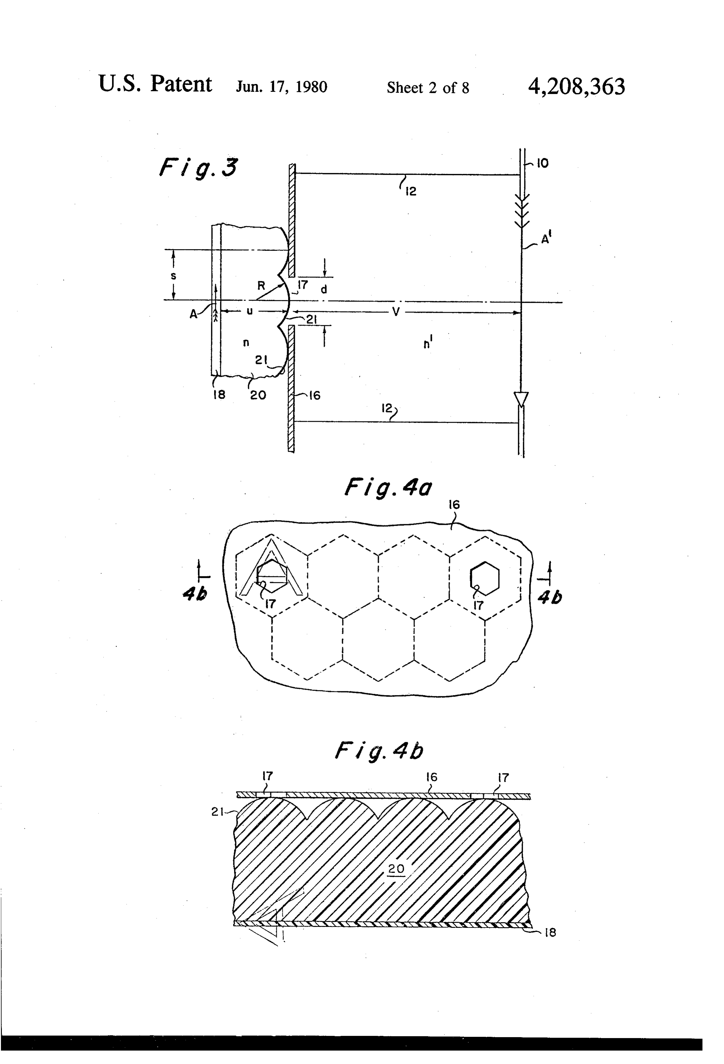
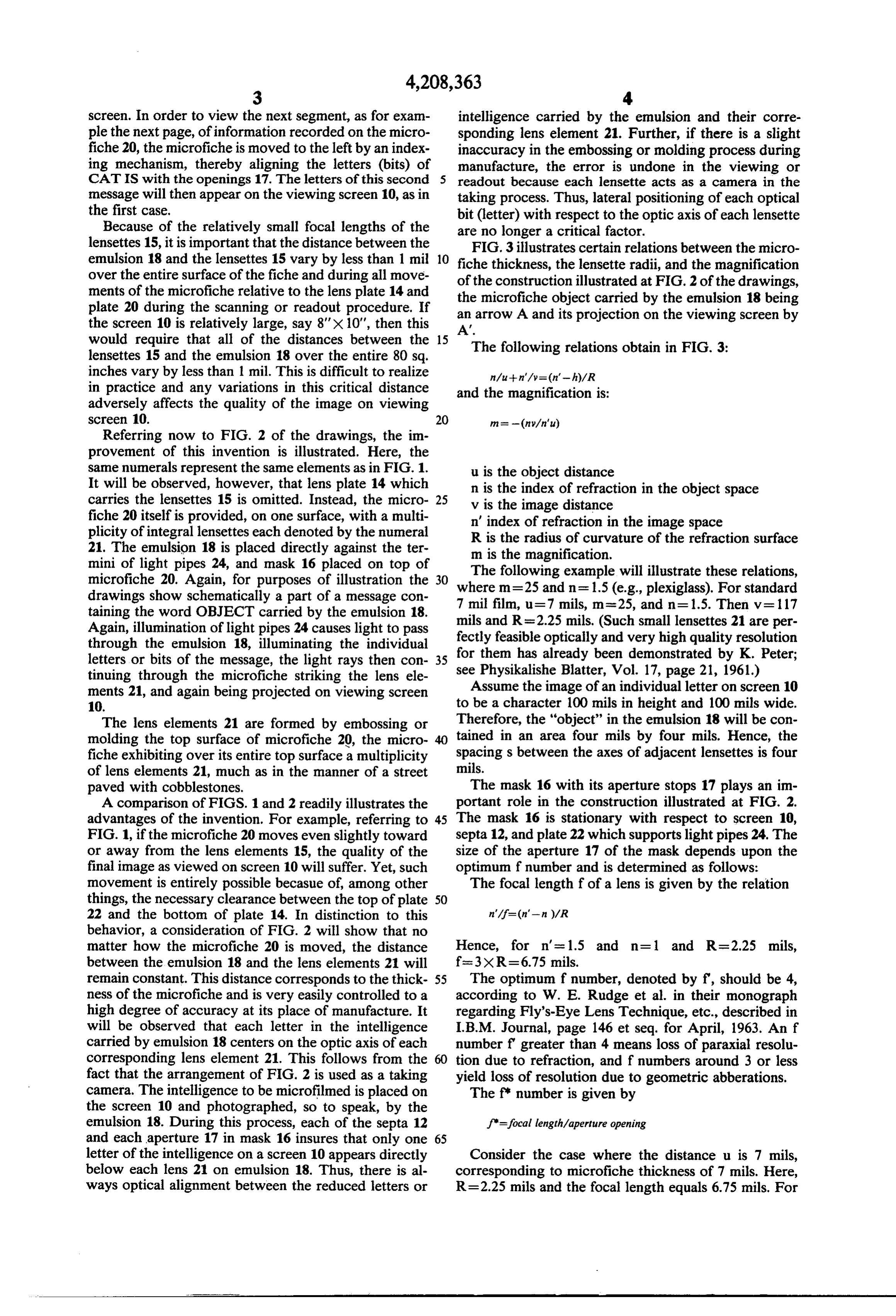
lensettes 15, it is important that the distance between the FIG. 3 illustrates certain relations between the micro emulsion 18 and the lensettes 15 vary by less than 1 mil 10 fiche thickness, the lensette radii, and the magnification over the entire surface of the fiche and during all move of the construction illustrated at FIG. 2 of the drawings, ments of the microfiche relative to the lens plate 14 and plate 20 during the scanning or readout procedure. If the an microfiche object carried by the emulsion 18 being arrow A and its projection on the viewing screen by the screen 10 is relatively large, say 8'X 10", then this A'.
would require that all of the distances between the 15 The following relations obtain in FIG. 3: lensettes 15 and the emulsion 18 over the entire 80 sq.
inches vary by less than 1 mil. This is difficult to realize nau--n'/y= (n'-h)/R in practice and any variations in this critical distance and the magnification is:
adversely affects the quality of the image on viewing screen 10. 20
Referring now to FIG. 2 of the drawings, the im provement of this invention is illustrated. Here, the same numerals represent the same elements as in FIG. 1. u is the object distance
It will be observed, however, that lens plate 14 which n is the index of refraction in the object space carries the lensettes 15 is omitted. Instead, the micro 25 v is the image distance fiche 20 itself is provided, on one surface, with a multi n' index of refraction in the image space plicity of integral lensettes each denoted by the numeral R is the radius of curvature of the refraction surface 21. The emulsion 18 is placed directly against the ter m is the magnification.
mini of light pipes 24, and mask 16 placed on top of The following example will illustrate these relations, microfiche 20. Again, for purposes of illustration the where m=25
and n=1.5 (e.g., plexiglass). For standard drawings show schematically a part of a message con 7 mil film, u-7 mils, m=25, and n=1.5. Then v = 117 taining the word OBJECT carried by the emulsion 18. mils and R=2.25 mils. (Such small lensettes 21 are per Again, illumination of light pipes 24 causes light to pass fectly feasible optically and very high quality resolution through the emulsion 18, illuminating the individual for them has already been demonstrated by K. Peter; letters or bits of the message, the light rays then con see Physikalishe Blatter, Vol. 17, page 21, 1961.) tinuing through the microfiche striking the lens ele ments 21, and again being projected on viewing screen Assume the image of an individual letter on screen 10 1). to be a character 100 mils in height and 100 mils wide. The lens elements 21 are formed by embossing or Therefore, the "object' in the emulsion 18 will be con molding the top surface of microfiche 20, the micro tained in an area four mils by four mils. Hence, the fiche exhibiting over its entire top surface a multiplicity spacings between the axes of adjacent lensettes is four of lens elements 21, much as in the manner of a street mils.
paved with cobblestones. The mask 16 with its aperture stops 17 plays an im A comparison of FIGS. 1 and 2 readily illustrates the portant role in the construction illustrated at FIG. 2. advantages of the invention. For example, referring to 45 The mask 16 is stationary with respect to screen 10, FIG. 1, if the microfiche 20 moves even slightly toward septa 12, and plate 22 which supports light pipes 24. The or away from the lens elements 15, the quality of the size of the aperture 17 of the mask depends upon the final image as viewed on screen 10 will suffer. Yet, such optimum f number and is determined as follows: movement is entirely possible becasue of, among other The focal length f of a lens is given by the relation things, the necessary clearance between the top of plate 50 22 and the bottom of plate 14. In distinction to this behavior, a consideration of FIG. 2 will show that no matter how the microfiche 20 is moved, the distance Hence, for n' = 1.5 and n=1 and R=2.25 mils, between the emulsion 18 and the lens elements 21 will f=3XR = 6.75 mils.
remain constant. This distance corresponds to the thick 55 The optimum f number, denoted by f, should be 4, ness of the microfiche and is very easily controlled to a according to W. E. Rudge et al. in their monograph high degree of accuracy at its place of manufacture. It regarding Fly's-Eye Lens Technique, etc., described in will be observed that each letter in the intelligence I.B.M. Journal, page 146 et seq. for April, 1963. An f carried by emulsion 18 centers on the optic axis of each number f greater than 4 means loss of paraxial resolu corresponding lens element 21. This follows from the tion due to refraction, and f numbers around 3 or less fact that the arrangement of FIG. 2 is used as a taking yield loss of resolution due to geometric abberations. camera. The intelligence to be microfilmed is placed on The f number is given by the screen 10 and photographed, so to speak, by the emulsion 18. During this process, each of the septa 12 f'=focal length/aperture opening and each aperture 17 in mask 16 insures that only one 65 letter of the intelligence on a screen 10 appears directly Consider the case where the distance u is 7 mils, below each lens 21 on emulsion 18. Thus, there is al corresponding to microfiche thickness of 7 mils. Here, ways optical alignment between the reduced letters or R=2.25 mils and the focal length equals 6.75 mils. For
Page 12
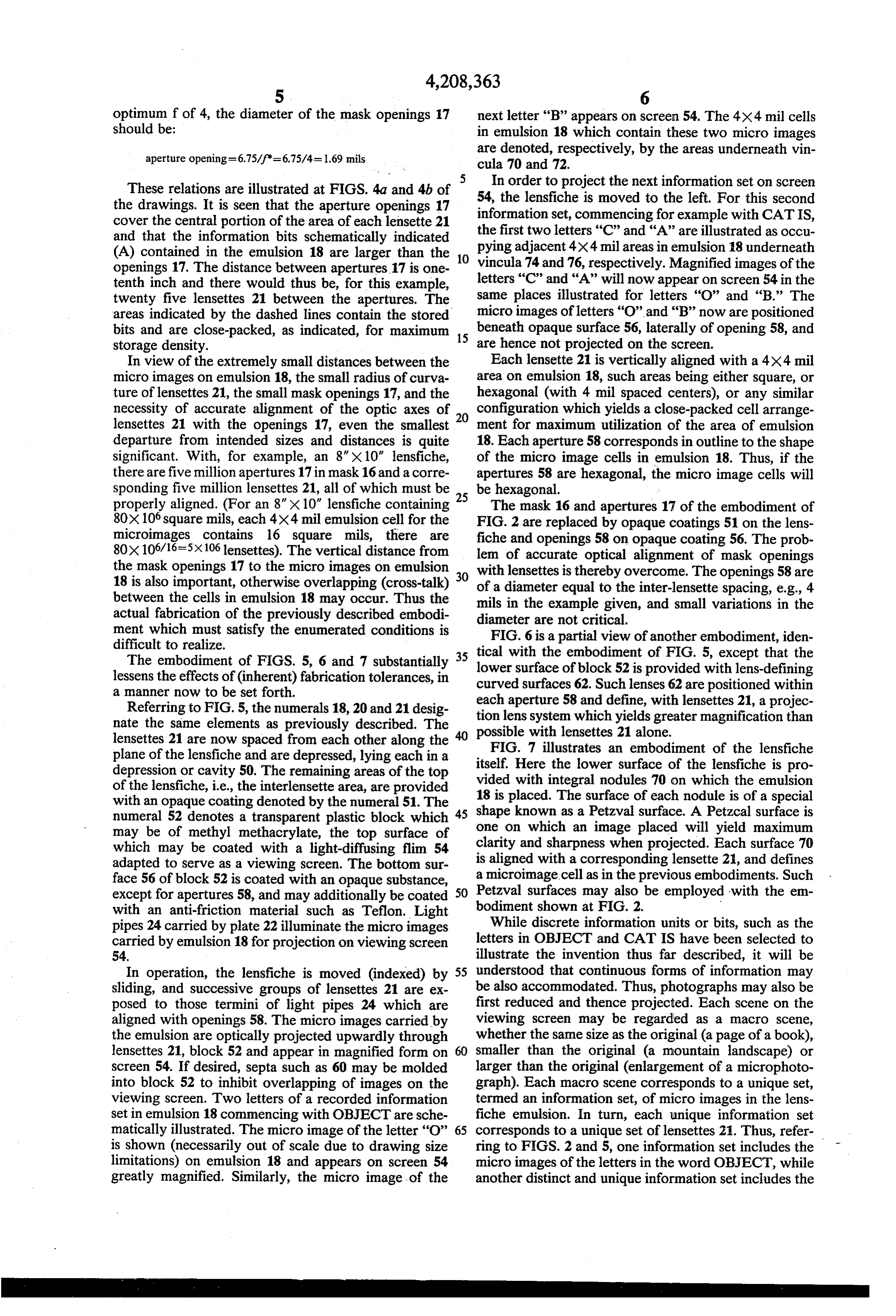
optimum f of 4, the diameter of the mask openings 17 next letter “B” appears on screen 54. The 4x4 mil cells should be: in emulsion 18 which contain these two micro images aperture opening=6.75/f=6.75/4= 1.69 mils are denoted, respectively, by the areas underneath vin
These relations are illustrated at FIGS. 4a and 4b of In order to project the next information set on screen 54, the lensfiche is moved to the left. For this second the drawings. It is seen that the aperture openings 17 information cover the central portion of the area of each lensette 21 the first twoset, commencing for example with CATIS, letters 'C' and 'A' are illustrated as occu and that the information bits schematically indicated pying adjacent 4X4 mil areas in emulsion 18 underneath (A) contained in the emulsion 18 are larger than the 10 openings 17. The distance between apertures 17 is one vincula 74 and 76, respectively. Magnified images of the tenth inch and there would thus be, for this example, letters “C” and “A” will now appear on screen 54 in the twenty five lensettes 21 between the apertures. The same places illustrated for letters "O' and “B.” The areas indicated by the dashed lines contain the stored micro images of letters "O' and “B” now are positioned bits and are close-packed, as indicated, for maximum 15 beneath opaque surface 56, laterally of opening 58, and storage density. are hence not projected on the screen. In view of the extremely small distances between the Each lensette 21 is vertically aligned with a 4X4 mil micro images on emulsion 18, the small radius of curva area on emulsion 18, such areas being either square, or ture of lensettes 21, the small mask openings 17, and the hexagonal (with 4 mil spaced centers), or any similar necessity of accurate alignment of the optic axes of 20 configuration which yields a close-packed cell arrange lensettes 21 with the openings 17, even the smallest ment for maximum utilization of the area of emulsion departure from intended sizes and distances is quite 18. Each aperture 58 corresponds in outline to the shape significant. With, for example, an 8" X 10" lensfiche, of the micro image cells in emulsion 18. Thus, if the there are five million apertures 17 in mask 16 and a corre apertures 58 are hexagonal, the micro image cells will sponding five million lensettes 21, all of which must be be hexagonal.
properly aligned. (For an 8" X 10" lensfiche containing 25 The mask 16 and apertures 17 of the embodiment of 80X106 square mils, each 4X4 mill emulsion cell for the FIG. 2 are replaced by opaque coatings 51 on the lens microimages contains 16 square mils, there are fiche and openings 58 on opaque coating 56. The prob 80x106/16-5X106 lensettes). The vertical distance from lem of accurate optical alignment of mask openings the mask openings 17 to the micro images on emulsion 30 with lensettes is thereby overcome. The openings 58 are 18 is also important, otherwise overlapping (cross-talk) of a diameter equal to the inter-lensette spacing, e.g., 4 between the cells in emulsion 18 may occur. Thus the mils in the example given, and small variations in the actual fabrication of the previously described embodi diameter are not critical.
ment which must satisfy the enumerated conditions is FIG. 6 is a partial view of another embodiment, iden difficult to realize.
The embodiment of FIGS. 5, 6 and 7 substantially 35 lower tical with the embodiment of FIG. 5, except that the lessens the effects of (inherent) fabrication tolerances, in curvedsurface surfaces of block 52 is provided with lens-defining 62. Such lenses 62 are positioned within a manner now to be set forth.
Referring to FIG. 5, the numerals 18, 20 and 21 desig tioneach aperture 58 and define, with lensettes 21, a projec nate the same elements as previously described. The possible lens system which yields greater magnification than lensettes 21 are now spaced from each other along the with lensettes 21 alone. FIG. 7 illustrates an embodiment of the lensfiche plane of the lensfiche and are depressed, lying each in a depression or cavity 50. The remaining areas of the top itself. Here the lower surface of the lensfiche is pro of the lensfiche, i.e., the interlensette area, are provided 18 is placed.integral vided with nodules 70 on which the emulsion
The surface of each nodule is of a special with an opaque coating denoted by the numeral 51. The numeral 52 denotes a transparent plastic block which 45 one shape known as a Petzval surface. A Petzcal surface is may be of methyl methacrylate, the top surface of on which an image placed will yield maximum which may be coated with a light-diffusing flim 54 isclarity and sharpness when projected. Each surface 70 aligned with a corresponding lensette 21, and defines adapted to serve as a viewing screen. The bottom sur a microimage cell as in the previous embodiments. Such face 56 of block 52 is coated with an opaque substance, except for apertures 58, and may additionally be coated 50 Petzval surfaces may also be employed with the em with an anti-friction material such as Teflon. Light bodiment shown at FIG. 2.
pipes 24 carried by plate 22 illuminate the micro images While discrete information units or bits, such as the carried by emulsion 18 for projection on viewing screen letters in OBJECT and CAT IS have been selected to 54. illustrate the invention thus far described, it will be In operation, the lensfiche is moved (indexed) by 55 understood that continuous forms of information may sliding, and successive groups of lensettes 21 are ex be also accommodated. Thus, photographs may also be posed to those termini of light pipes 24 which are first reduced and thence projected. Each scene on the aligned with openings 58. The micro images carried by viewing screen may be regarded as a macro scene, the emulsion are optically projected upwardly through whether the same size as the original (a page of a book), lensettes 21, block 52 and appear in magnified form on 60 smaller than the original (a mountain landscape) or screen 54. If desired, septa such as 60 may be molded larger than the original (enlargement of a microphoto into block 52 to inhibit overlapping of images on the graph). Each macro scene corresponds to a unique set, viewing screen. Two letters of a recorded information termed an information set, of micro images in the lens set in emulsion 18 commencing with OBJECT are sche fiche emulsion. In turn, each unique information set matically illustrated. The micro image of the letter "O” 65 corresponds to a unique set of lensettes 21. Thus, refer is shown (necessarily out of scale due to drawing size ring to FIGS. 2 and 5, one information set includes the limitations) on emulsion 18 and appears on screen 54 micro images of the letters in the word OBJECT, while greatly magnified. Similarly, the micro image of the another distinct and unique information set includes the
Page 13
letters in the phrase CAT IS. As shown, a lensette is they require space on the side of the lensfiche opposite aligned and associated with a single micro image. The the viewing screen.
same correspondence holds in the case of continuous FIG. 8 illustrates such a front lighting embodiment. information. The various information sets are interlaced Referring now to FIG. 8, the numeral 82 represents in the sense of interlocked fingers and are also distinct as 5 one of a plurality of light-pipe elements which lie in are the pieces of a jigsaw puzzle. The totality of infor troughs in the bottom surface of transparent plastic mation sets recorded on the lensfiche forms a mosaic plate 52. The light-pipe 82 is preferably externally whose individual elements are the dispersed area of the coated so as to produce total internal reflection. Simi various information sets. larly, the surface and end of the trough in which the The same advantages and mode of operation of the O light-pipe 82 is positioned may be mirrored. As indi invention follow for a projection lens array which re cated by the arrows coming from the left in FIG. 8, quires lensettes 21 to be concave with respect to the top light passing down light-pipe 82 is reflected at the end surface of the lensfiche 20 instead of convex as has been of the tube and into one of the lensettes 21. This light illustrated. Further, in lieu of proturberances (convex 15 continues through fiche 20 until striking the lower por lensettes) or depressions (concave lensettes) optical tion where the emulsion 18 is located. A portion of the anisotropys in the fiche may be employed for the pur light is then reflected upwardly. Of all this light re flected upwardly, a portion will define a light cone pose of changing the direction of light rays. Accord through ingly, the phase "optically active surface' appearing in the adjacent lensette 21. Thus, the micro-image immediately below the lensette through which the light the claims is intended to embrace these distinct yet 20 cone equivalent constructions. passes, as indicated, is projected onto the screen 54 The lensfiche is moved relative to the mask apertures, of Intheorder plate 52.
to read or scan the next information set, i.e., to successively expose distinct information sets, by an the next stage indexing mechanism, not illustrated, and which forms left so that thefor example, the fiche 20 is indexed to the lensette 21 associated with the illustrated no part of this invention. The information sets and mask openings may be rectangularly arranged such as shown 25 light from cone is now the lensette through which the light light pipe 82 passes to illuminate the next adjacent at FIG. 2 of the noted Waly application, and thus re micro-image quire both row and column indexing motions. The in ther explained,oneach emulsion 18. As will presently be fur aperture 58 of transparent plate 52 formation sets and mask openings may also be arranged has associated therewith an adjacent end of a light-pipe in a skew manner, such as shown at FIGS. 4 and 5 of the 30 82. The optic axis, as indicated, will remain the same noted Waly patent, and thus require only column index while the fiche 20 is indexed to successively read out the 1ng. information.
From a considerationn of FIGS. 2 and 5 of the draw FIG. 9 illustrates one step in fabricating the front or ings, it may be readily visualized that the same results top illumination embodiment shown at FIG.8. Initially, are obtained with the microfiche stationery with respect 35 a clear plastic such as methyl methacrylate may be to the screen and the mask relatively movable. Thus, coated with a substance having a different index of referring particularly to FIG. 2, by placing a light pipe refraction so as to produce total internal reflection. 24 underneath each microimage and fixing the micro Next, a set of dies which will give the configuration fiche relative to the screen 10 and supporting plate 22, illustrated at FIG. 9 is applied to the top and the bottom indexing movement of the mask 16 will expose each set 40 of a plane methyl methacrylate sheet. The dies being of microimages carried by emulsion 18 to an aperture pressed together, the result as indicated at FIG. 9 fol 17, with attendant projection on the screen 10. With the lows. The dies, for purposes of clarity, are not illus FIG. 5 construction, each lensette 21 may be provided trated at FIG. 9. That is to say, the plastic sheet which with a corresponding light pipe 24. The opaque coating was once plane on both surfaces is now transformed 56 on the bottom of screen block 52 is replaced with an 45 into a plastic sheet having a series of regular and longi opaque mask having apertures 58 of the same size as tudinal indentations for the purpose of defining the shown, the mask undergoing sliding (indexing) motion equivalent of individual light-pipes. As the next step, with respect to the stationary microfiche and screen and the forward end, as viewed at FIG. 9, of the light-pipes positioned between them. Again, each set of microim 82 is cut as indicated by the dashed lines to produce a ages carried by the microfiche is sequentially exposed 50 saw-toothed configuration as partially indicated at FIG. through mask openings 52 for projection onto the view 10. The ends of these forward light-pipes 82 are suitably ing screen. The opaque coatings 51 (FIG. 5), as before, beveled and coated with a reflecting surface, if desired, inhibit cross-talk (overlapping of projected images). so that when placed in troughs in the bottom of plate 52 However, the septa 12 of FIG. 2 and 60 of FIG. 5 are light will be reflected downwardly, as indicated at FIG. omitted in the movable mask embodiment. 55 8. Again, referring to FIG. 9, the outer rearmost end of It will be noted that upon changes in dimensions of the light-pipe ensemble is wrapped or curled about the the lensfiche 20 due to either temperature or humidity indicated axis, it being recalled that the light-pipe en fluctuations, the optical registry between the emulsion semble is flexible. This results in the roll 80 shown at carried intelligence and the lensettes 21 will not be FIG. 11, with the individual series of saw-toothed sets disturbed. They will both suffer or undergo the same 60 of light-pipes 82 placed in the indicated bottom of plate displacement. 52. The individual light pipe termini in all of the saw An embodiment will now be described wherein the toothed sets are spaced from each other, and together, lensfiche is illuminated from the top or front, in distinc these termini form a regular array. When light exits tion to bottom or rear lighting as in the previously de from these termini, a regular array of spaced apart light scribed constructions. By reference to FIG. 5, for exam 65 sources is thus defined to illuminate microimages on the ple, a rear lighting mode requires both lensfiche sur emulsion of a microfiche.
faces to be transparent. Further, the location of the light FIGS. 12 and 13 indicate the trough formation in the pipes adds thickness to the entire reader ensemble since bottom of plate 52, and show that as the distance to the
Page 14
ends of the saw-teeth is increased, the number of indi movement between the microfiche and screen or be vidual light-pipes 14 which abut reflecting surfaces tween the (omitted) mask and microfiche is required for decreases. FIG. 14 illustrates how the various ends of readout. FIG. 17a illustrates, schematically, a single the individual light-pipes 82 abut the ends of the troughs LED of the grid.
in plate 52. In each of the described embodiments the actual scale Reference now to FIG. 15 will further illustrate the has not been shown in all cases because of drawing size front or top lighting embodiment. The ends of the indi limitations. The same holds true for the number of len vidual light pipes 82 are denoted by the numerals 86, 88, settes between several of the mask apertures. In some 90 and 92. The adjacent lensettes 21, through which the cases angles have been greatly exaggerated for the pur reflected light passes upwardly for projection on screen 10 pose of clarity.
54, are designated by numerals 94,96. As indicated, the I claim:
lensettes 21, corresponding to apertures 58, through 1. A method of making a plurality of adjacent light which the projections are made are spaced 100 mils. pipe elements, including the steps of, apart, their being 4X4 micro-image storage areas on the (a) die deforming the top and bottom surfaces of a emulsion 18 between the apertures 58 through which 15 sheet of transparent, bendable, plastic material, in the projection proceeds.
FIG.16 further illustrates a construction wherein top the general form of a flat elbow, said elbow having or front lighting is employed. FIG.16 may be viewed as a forward end and a rearmost end, a further stage in the construction partially illustrated at (b) said die deformation producing a plurality of side FIG. 11. In FIG. 11, only half of the plate 52 is illus 20 by-side light conducting elements joined at their trated as provided with the illuminating light-pipes 82. mid-sections longitudinally therealong, said light In FIG. 16, both sides of the plate 82 are provided with conducting elements being parallel to the sides of a roll 80. As indicated at FIG. 16, the top ends of the the flat elbow, two rolls 80 are illuminated as indicated, the top ends (c) wrapping the rearmost end of the flat elbow sheet defining a plurality of parallel light-pipe ends arising 25 about an axis normal to its end and located adjacent through the process indicated by wrapping at FIG. 9. one edge of the flat elbow sheet, Reference to FIGS. 17 and 17a illustrates still another (d) whereby the wrapped, rearmost end of the sheet embodiment, wherein motion of the microfiche is not defines light pipes in the form of a solid spiral roll necessary for readout. In lieu of light pipes illuminating and whereby the remaining end, the forward end, the rear of the microfiche, a grid of light emitting diodes 30 of the flat sheet defines a plurality of side-by-side (LED) may be employed, with one LED beneath each light pipe termini, lensette. The mask 56 and apertures 58 may then be (e) the additional step of cutting the forward end to omitted from the embodiment of FIG. 5, and a consider form a plurality of sawtooth sets of light pipe ter ation of FIG. 5 shows that by placing such a grid be mini, these termini being in a regular array and neath a (stationary) microfiche 20, in lieu of light pipes, 35 spaced apart from each other, whereby the spaced each LED in the grid will illuminate a corresponding apart termini, when light is passed into the solid and unique microimage in emulsion 18 and associated spiral roll, supply light to illuminate microimages lensette 21. By energizing different sets of LEDS in the on a microfiche.
grid, as indicated by the several switch positions, differ 2. The method of claim 1 including the additional ent sets of microimages may be illuminated for projec steps of beveling the spaced apart light pipe termini and tion through the lensettes and onto the viewing screen. coating them with a reflecting medium. By this substitution of LEDs for the light pipes, no k
Provenance
- Collection
- Cited prior art
- Original PDF
- patentimages.storage.googleapis.com →
- Filed
- 1976-09-13
- Pages
- 14
- Method
- pdftotext (the PDF's own text layer) + pdftoppm 300dpi page scans
- Source
- Google Patents bibliographic record
- Granted
- 1980-06-17
- Inventors
- George J. Yevick; Izon Corp
- Transcribed from
- patentimages.storage.googleapis.com →