patent · US4141626
Method of and apparatus for collecting solar radiation utilizing variable curvature cylindrical reflectors
27 February 1979
Page 1 — bibliographic record
United States Patent (19) (11) 4,141,626 Treyti et al. 45) Feb. 27, 1979 54 METHOD OF AND APPARATUS FOR 4,033,676 7/1977 Brantley, Jr. et al................ 350/295 COLLECTING SOLAR RADATION 4,046,462 9/1977 Fletcher et al. ..................... 350/295
UT LIZNG WARIABLE CURVATURE
CYLNDRICAL REFLECTORS OTHER PUBLICATIONS 75 Inventors: William J. Treytl, San Jose; Arthur J. Total Energy, Distributed Collector Systems and Re Stemmons, Los Gatos; Gerry B. search and Development Projects: Semiannul Report Andeen, Menlo Park, all of Calif. (26-27 Jan. 1976, Atlanta, Georgia) pp. 45-52 and
(73) Assignee: FMC Corporation, San Jose, Calif. Primary Examiner-F. L. Evans 21 Appl. No.: 801,671 Attorney, Agent, or Firm-R. S. Kelly; T. J. 22 Filed: May 31, 1977 McNaughton 51 int. C.’............................ G02B 5/10; F24J 3/02 57 ABSTRACT 52 U.S. C. .................................... 350/295; 126/270; A heliostat apparatus includes a frame which is rotat 350/289 able about an axis which is parallel to the aperture plane 58 Field of Search ....................... 350/292, 295, 289; of an elongate receiver. A plurality of flat flexible mir 126/270, 271; 353/3 ror elements are mounted to the frame between several 56) References Cited parallel, uniformly spaced resilient beams which are
pivotally connected at their ends to the frame. Channels are mounted to the sides of the beams for supporting the 412,724 10/1889 Calver .................................. 126/270 edges of the mirror elements. Each of the beams has a 503,004 8/1893 Severy ..... ... 126/270 longitudinally varying configuration designed to bow 603,317 5/1898 Calver .................................. 126/270 into predetermined, generally circular curvatures of 811,274 1/1906 Carter ...... ... 126/271 varying radii when the center of the beam is deflected 1,951,404 3/1934 Goddard ...... 350/295 X relative to the pivotally connected ends of the beams. 2,579,225 12/1951 Borst et al. ........................... 350/295 2,664,785 1/1954 Roehrig ... ... 350/295 X All of the parallel resilient beams are simultaneously 2,707,903 5/1955 Trombe 126/270 X deflected by a camshaft assembly extending through 2,982, 179 5/1961 Lace ..................................... 350/295 openings in the centers of the beams, whereby the mir 3,713,727 1/1973 Markosian et al... 126/271 X ror elements together form an upwardly concave, cylin 3,841,738 10/1974 Caplan ................. 126/271 X drical reflecting surface. The heliostat is rotated about 3,861,379 1/1975 Anderson, Jr. .. ... 126/271 its axis to track the apparent diurnal movement of the 3,884,217 5/1975 Wartes ............. ... 126/270 sun, while the reflecting surface is substantially simulta 3,889,531 6/1975 Suga..... ... 126/270 X neously bowed into a cylindrical trough having a radius 3,892,433 7/1975 Blake ... ... 126/270 X 3,905,352 9/1975 Jahn ..................................... 126/270 adapted to focus incident light at the plane of the re 3,906,927 9/1975 Caplan. 350/295 X ceiver aperture.
3,915, 147 10/1975 Rineer .......... . 126/271 4,022,523 5/1977 Lindonen et al. .................... 350/295 11 Claims, 9 Drawing Figures
Int a
Page 2
Drawing sheet — no readable text.
Page 3
Drawing sheet — no readable text.
Page 4
Drawing sheet — no readable text.
Page 5
Drawing sheet — no readable text.
Page 6
U.S. Pat. No. 3,884,217 to Wartes shows a distributed
METHOD OF AND APPARATUS FOR receiver system which is similar to the system of the COLLECTING SOLAR RADATION UTILIZING Anderson patent. The Wartes patent discloses a mecha VARABLE CURVATURE CYLNDRICAL nism for rotating the mirrors thereof into defocused REFLECTORS positions in the event that the mirrors need protection
BACKGROUND OF THE INVENTION
from the elements (hail, sand, etc.) or when the central receiver is in an overheated condition.
1. Field of the Invention U.S. Pat. No. 3,915,147 to Rineer discloses a system The present invention generally relates to heliostats in which two rigid reflector members, which together and more particularly concerns heliostats which include 10 form a trough-shaped reflector, are shifted into a defo a cylindrical reflecting surface for focusing light on the cused orientation with respect to the associated receiver elongate aperture of an elongate solar energy receiver. when said receiver needs to be cooled below the con 2. Description of the Prior Art densation point of the heat transfer fluid therein. U.S. Pat. No. 3,892,433 to Blake discloses a "point” As indicated by the Rineer, Blake, and Wartes pa type of central receiver system which includes a central 15 tents, the conventional method of providing defocusing light receiver and a fan-shaped array of heliostats sur of incident light comprises changing the relative orien rounding the central receiver. Each heliostat includes a tation of rigid reflectors relative to the receiver, rather reflecting surface which is spherical and upwardly con than bending the reflectors themselves into defocused cave. The curvature of the reflecting surfaces of each configurations.
heliostat is fixed and is chosen, among other parameters, 20 SUMMARY OF THE INVENTION according to the distance between the heliostat and the central receiver. The reflecting surface of each heliostat A principal object of the present invention is to pro is mounted for pivoting orthogonally about a vertical vide a method of collecting solar radiation on a elongate axis through its center, to thereby permit general eleva aperture of a solar receiver which eliminates concern tional and azimuth tracking of the sun. It is indicated in 25 about off-axis astigmatic focusing errors. The method this patent that the heliostats do not accurately focus generally comprises the steps of concurrently rotating sunlight into the aperture of the receiver throughout the several reflectors about transversely spaced, fixed axes day. Rather, some inaccuracy is inherent in the system which are parallel to the receiver aperture so as to gen due to off-axis astigmatic errors in both focal planes of erally continuously direct the solar radiation incident the reflecting surfaces which result from the fixed ra 30 thereon toward the aperture as the sun changes its posi dius of curvature of the individual reflecting surfaces tion in the sky, and substantially simultaneously with and the fixed mode of orthogonal rotation. such concurrent rotation, bending the several reflectors A similar point type of central receiver system, which into various different cylindrical curvatures with the has been studied by the Georgia Institute of Technol curvatures of the respective reflectors being set accord ogy, is disclosed at pages 69-73 of the publication enti 35 ing to the off-axis angle between the incident radiation tled, "Total Energy, Distributed Collector Systems and and a plane which is normal to their fixed axes of rota Research and Development Projects' published by the tion and also according to the particular distances be Aerospace Corporation of El Segundo, Calif. on Mar. tween the respective reflectors and the solar receiver. 26, 1976 for the United States Energy Research and Another principal object of the present invention is to Development Administration in connection with 40 provide an apparatus for focusing light on an elongate ERDA Contract No. E(04-3)-1 101. The system as de aperture of a solar receiver such apparatus comprising a scribed therein includes heliostats arranged in a hexago frame which is rotatable about an axis to track the ap nal field about the central receiver. Each heliostat in parent movement of the sun, a flexible reflector, and a cludes a flat circular mirror bent into a fixed curved mechanism for mounting the reflector to the frame to form by a bending device, which device is not specifi 45 form a cylindrical reflecting surface having a variable cally described. The individual mirrors are, as in the curvature in a plane normal to the axis of rotation system of the aforenoted Blake patent, held at fixed thereof. The frame is rotated to track the apparent diur radii dependent upon their respective distances from the nal movement of the sun, while the curvature of the central receiver. As with the heliostats of the Blake reflector is changed to focus incident radiation upon the patent, the heliostats disclosed in this publication will 50 elongated receiver aperture. also be subject to focusing errors resulting from off-axis Another object of the present invention is to provide astigmatism. a solar-thermal power system which utilizes an elon U.S. Pat. No. 3,861,379 to Anderson discloses a re gated central solar receiver and a plurality of reflector ceiver system, which may be broadly considered to be. apparatuses as aforedescribed with each individual re a small scale, line type of central receiver system. In a 55 flector apparatus being generally continuously adjusted line type of central receiver system, the receiver is ele to accomplish the desired tracking of the sun. vated relative to a field of heliostats and is elongated The reflector mounting mechanism preferably in along an axis which is driented in a selected direction. cludes resilient deflection beams for supporting the In the line type of system the heliostats have cylindrical edges of flat flexible mirrors and a mechanism for con or rectangular reflecting surfaces which are mounted 60 currently deflecting the centers of each of the beams for rotation about axes which are parallel to the axis of and thereby bending the mirrors to form a cylindrical the central receiver. The system of the Anderson patent trough having a variable curvature which is dependent includes a central cylindrical receiver fixedly mounted on the amount of deflection of the centers of the beams. to a framework and a plurality of parallel, elongate The amount of deflection of the beams is determined reflectors, each having flat rectangular shapes, which 65 according to the off-axis angle between the incident are rotatably mounted to the framework. The patent radiation and the normal plane of the cylindrical mirror indicates that the reflectors may have cylindrical or and also the distance between the reflector and the parabolic cross-sections. plane of the receiver aperture.
Page 7
In a preferred embodiment of the heliostat apparatus short braces 36 are connected between the ends of cen of the present invention, the rotatable frame includes tral beam 18 and the centers of diagonal rails 30-33. two structural members extending parallel to the axis of A pair of spaced parallel rails 38 are connected at one rotation of the frames, and the parallel deflection beams side of the frame respectively between the rails 20 and are mounted transversely between the two structural 5 22 adjacent central beam 18 and the beam 28. Another members, with the ends of the beams being pivotably pair of spaced parallel rails 39 is connected between the connected to the two structural members. The trans center beam 18 and the beam 28 at the center of the verse edges of the flat mirrors are slidably retained in frame structure. A further pair of spaced parallel rails channels affixed to the sides of the beams. A cam rod 40 is connected at the other side of the frame between extends through openings in the centers of the respec O the rails 24 and 26 and the beam 28. A cylindrical sleeve tive deflection beams, and a plurality of can elements 44 is affixed to the parallel rails 38 and 39 by plates 42, are mounted on the cam rod for deflecting the beams the sleeve being mounted to coaxial with the desired into upwardly concave configurations. The cam rod is axis of rotation R-R of the frame 12. A plate 46 (FIG. driven to cause the cam elements to deflect the beams in 1) having a stub shaft 48 mounted thereon is connected unison into the selected amount of curvature. 5 to the pair of rails 40, with the stub shaft also being BRIEF DESCRIPTION OF THE DRAWINGS coaxially aligned with the axis of rotation R-R. The sleeve 44 receives, and is pinned to, one end 45a (see
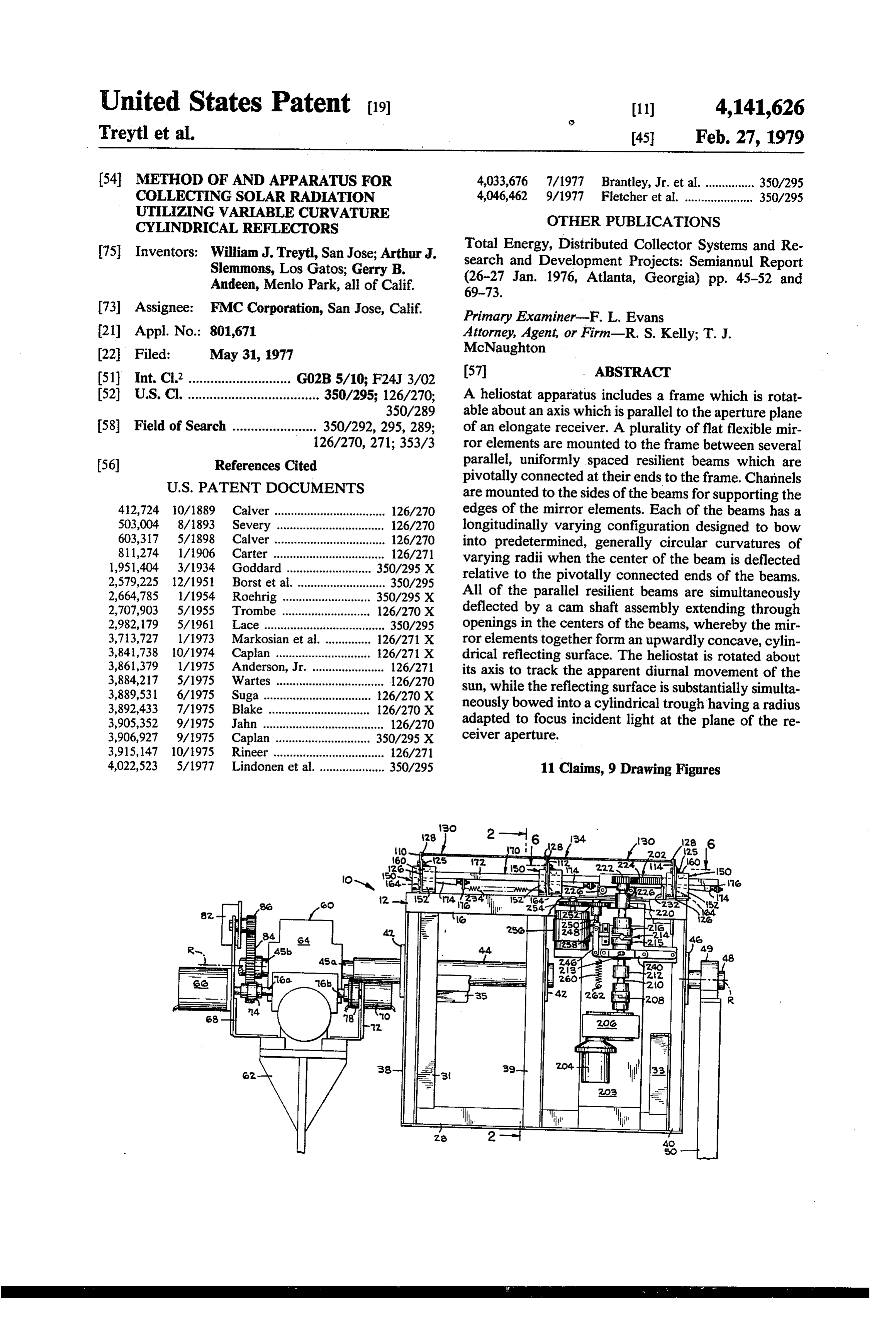
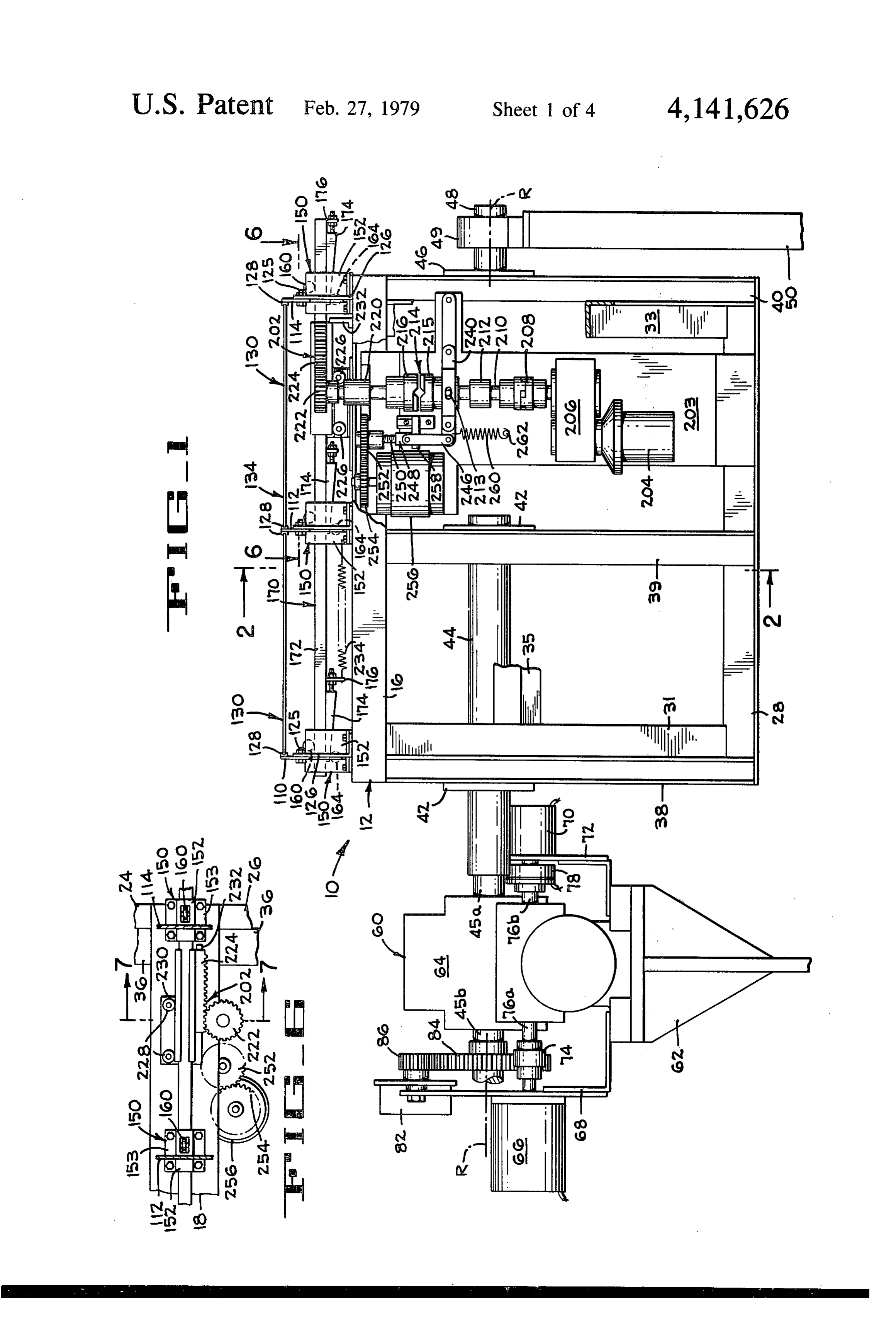
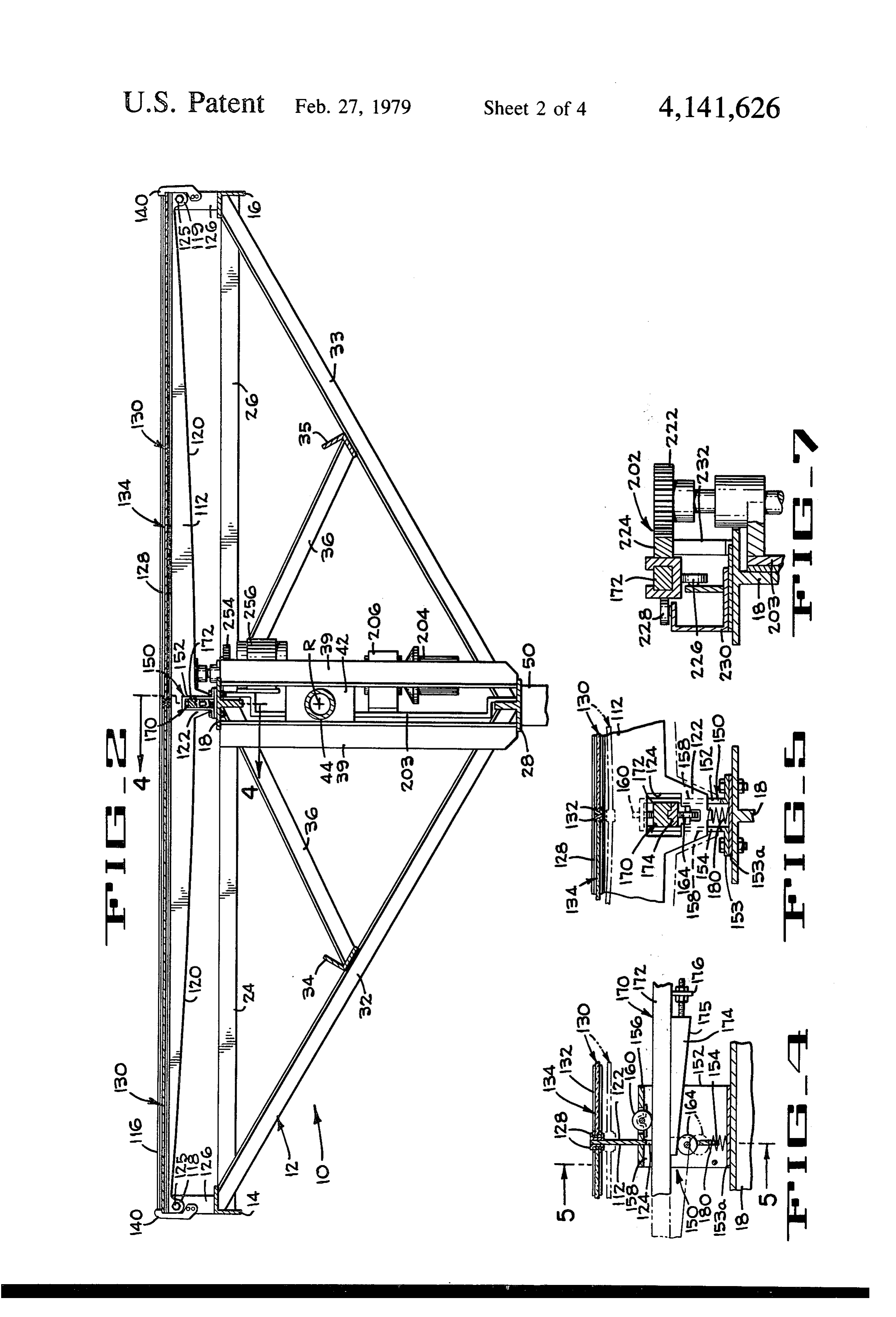
FIG. 1 is a side elevational view of the heliostat appa FIG. 1) of a double-ended drive shaft of a frame drive ratus of the present invention, the mirror retaining clips assembly 60, while the fixed stub shaft 48 is permitted to (shown in FIG. 2) having been removed for the sake of 20 freely rotate in a bearing element 49 which is secured to clarity. a rigid support frame member 50 (shown in part in FIG. FIG. 2 is a reduced sectional view of the heliostat 1).
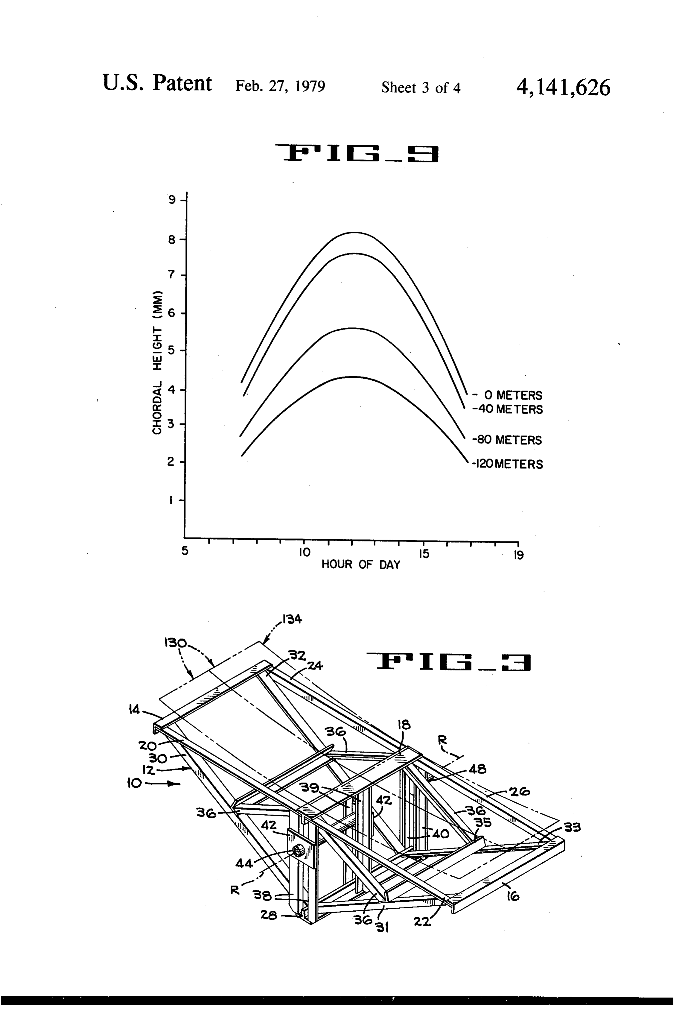
apparatus taken on line 2-2 of FIG. 1. The frame drive assembly 60 is mounted to a fixed FIG. 3 is a perspective view of the rotatable frame of support frame 62 (shown in part in FIG. 1) and includes the heliostat apparatus shown in FIGS. 1 and 2, the 25 a gear reduction device 64, a stowing motor 66 mounted variable curvature, cylindrical reflecting surface of the by a bracket 68 to the frame 62, and a tracking motor 70 heliostat being diagrammatically depicted in dashed mounted by a bracket 72 to the frame 62. The stowing outline. motor 66 is coupled by a coupling 74 to one end 76a of FIG. 4 is an enlarged section taken on line 4-4 of a double-ended input shaft of the gear reduction device FG, 2. 30 64. The tracking motor 70 is connected through an FIG. 5 is a section taken on line 5-5 of FIG. 4. electrically operated clutch 78 to the other end 76a of FIG. 6 is a section taken on line 6-6 of FIG. 1. the double-ended input shaft of the gear reduction de FIG. 7 is an enlarged section taken along line 7-7 of vice 64. The tracking motor 70 may be a conventional FIG. 6. bi-directional D.C. stepper motor capable of 200 steps FIG. 8 is a diagrammatic, end elevational view of a 35 per revolution. The stowing motor 66 may be a conven central receiver, solar-thermal power system which tional A.C. induction motor capable of operating at employs the heliostat apparatus of the present inven 1250 RPM. The gear reduction device 64 has a gear tion. ratio of 5,000:1 and has an output shaft having two ends FIG. 9 is a graph illustrating the relationship of the 45a and 45b (the latter being broken away in FIG. 1). As chordal heights of the cylindrical reflecting surfaces of 40 previously stated, the shaft end 45a is anchored within various heliostats in the array of the central receiver the sleeve 44 extending from the heliostat frame 12. The system of FIG. 8. other end 45b of the output shaft may be connected to DESCRIPTION OF THE PREFERRED another (non-illustrated) heliostat frame 12 to concur EMBODIMENTS rently drive such other frame. A shaft encoder 82 is 45 shown as being mounted above the stowing motor 66,
Referring now more particularly to FIGS. 1-3 of the and a gear 84 is mounted on the output shaft end 45a to drawings, it will be seen that the heliostat apparatus 10 engage a gear 86 attached to the input shaft of the shaft of the present invention includes a truss-like frame 12 encoder.
(FIG. 3) which is rotatable about an axis of rotation 50 The heliostat 10 further includes an adjustable reflec R-R. The frame 12 includes a rectangular top section tor assembly which is mounted to the upper rectangular comprised of a central transversely extending beam 18; section of the frame 12 and includes three uniformly two transversely extending rails 14 and 16 which form spaced, parallel, resilient deflection beams 110, 112, and the short sides of the rectangular section; two longitudi 114 and a plurality of mirror elements 130 mounted to nally extending and aligned rails 20 and 22 connecting such deflection beams. The deflection beams 110-114 one end of the rail 14 to the beam 18 and one end of the 55 are formed from resilient sheet material, such as inch rail 16 to the beam 18, respectively, and together form aluminum and extend parallel to the side rails 20-26 of ing one long side of the rectangular section; and two the frame with their flat surfaces being oriented verti further aligned rails 24 and 26 connecting the other ends cally. Each of the beams has a straight top edge 116 of the rails 14 and 16 to the central beam 18 and forming (FIG. 2), downwardly extending projections 118 and the other longside of the rectangular section. The frame 119 at its end, a bottom edge 120 which has a compound 12 further includes a truss section comprising an in hyperbolic curvature that is symmetrical about the cen verted T-shaped beam 28 at the apex of the truss section ter of the beam, and a downwardly extending projec (extending in spaced parallel relationship to beam 18) tion 122 at the center of the beam (FIG. 5). Apertures and diagonally extending rails 30, 31, 32, and 33 which are provided in the end projections 118 and 119, and an connect the ends of the beam 28 to the ends of the side 65 opening 124 (FIG. 5) is provided through the center of rails 14 and 16. Two further bracing rails 34 and 35 each beam. The resilient deflection beams are formed extend between the centers of opposing diagonal rails such that when the center of a beam is transversely 30 and 32 and rails 31 and 33, respectively. Finally, four deflected relative to the end of the beam, the beam will
Page 8
bow in a manner such that the straight top edge 16 will rollers 160 (FIG. 4) are mounted to the top walls 156 of deform generally into an arc of a circle. The curvature the brackets 152 in a manner such that the shafts of the of the beam at different amounts of center deflection rollers 160 are oriented transversely relative to the cam will be understood to depend on the longitudinally shaft assembly 170. The top of each roller 160 extends variance in elastic stiffness-which is dependent on the 5 upwardly through an opening in the top wall 156 of the longitudinal variance in cross-section of the beam. respective bracket (FIG. 4). The guide rollers 160 pro The end projections 118 and 119 of the deflection vide bearings for the adjacent upper surfaces of the cam beams 110, 112, 114 are pivotally attached by bolts 125 shaft assembly 170. A cam follower roller 164 is (FIG. 2) to L-shaped brackets 126 which are affixed to mounted in the center projection 122 of each deflection the respective end rails 14 and 16 of the frame 12. Chan 10 beam at the bottom of the center opening 124 thereof, nels 128 (FIG. 1) having a U-shaped cross-section for with the shaft of roller 164 being mounted parallel to receiving the long edges of rectangular mirror elements the wall of the respective deflection beam (FIG. 5). The 130 are welded to the sides of the deflection beams cam follower rollers 164 provide low-friction bearings adjacent the top edges 116 thereof. More specifically, for the adjacent linear camming surfaces of the cam the deflection beams 110 and 114 at the sides of the 5 shaft assembly 170.
heliostat 10 have channels 128 mounted to their inner As shown in FIG. 1, 2, 4 and 5, the camshaft assem side surfaces, and the central deflection beam 112 has a bly 170 comprises a rectangular shaft 172 and three channel 128 mounted on each side surface thereof. The linear cam elements 174 mounted against the bottom channels 128 slidingly receive rectangular mirror ele surface of the shaft 172 at uniform spacings correspond ments 130 with the long edges of the mirror elements 20 ing to the spacings between the three deflection beams 130 being contained within opposing channels of adja 110-114. The cam elements 174 are wedge-shaped, with cent deflection beams. the linear camming surfaces 175 (FIG. 4) thereofhaving A preferred form of mirror element 130 is comprised a slope selected according to the desired amount and of a 20 inch by 60 inch second surface glass mirror rate of deflection of the deflection beams 110-114. Each which is 1/16-inch thick and leaving a -inch protection 25 of the cam elements 174 has a longitudinally extending layer of polystyrene foam insulation (not shown) glued rib formed on the upper surface thereof which is re by a soft adhesive to the silvered back surface thereof ceived within a groove formed longitudinally in the with a steel channel 132 (FIGS. 4 and 5) surrounding bottom surface of the shaft 172 (see FIG. 5), and each the edges of the composite glass and foam structure. cam element is adjustably bolted to a stub 176 extending Two of such mirror elements 130 are retained end-to 30 from the bottom of the shaft 172 (FIG. 4) so that its end between adjacent deflection beams, thus providing position on the shaft can be varied. a composite reflecting surface 134 (FIG. 3) of a mosaic It will be seen from FIGS. 4 and 5 that as the shaft form, which is 40 inches wide by 120 inches long. The 172 is longitudinally shifted in the associated beam short inner ends of the mirror elements 130 are in abut openings 124, the cam follower rollers 164 will be ment (FIG. 5) at the centers of deflection beams 35 pushed down to downwardly deflect the centers of the 110-114, and the short outer ends of the mirror elements deflection beams. 110-114 relative to the ends thereof. are aligned with the ends of the deflection beams. To That is to say, each deflection beam is deflected such retain the two longitudinally aligned mirror elements that the mirror-mounting channels 128 attached thereto between adjacent opposing channels 128, several clips are bent into upwardly concave configurations which 140 are employed (two only being shown in FIG. 2). are each generally in the form of an arc of a circle with The clips 140 are bolted to the brackets 126. the radius of the arc being variable and dependent on The centers of the deflection beams 110, 112, 114 are the amount of deflection of the center of the beam. The guided by cam shoe assemblies 150 (FIGS. 4 and 5) phantom lines in FIGS. 3, 4, and 5 illustrate a down which permit the respective beams to be deflected in a wardly deflected and focused configuration of the mir transverse direction which is normal to the axis of rota 45 ror elements 130. FIGS. 4 and 5 illustrates the camming tion R-R of the reflecting surface 134. The cam shoe action of the shaft assembly 170 on one of the deflection assemblies 150, as shown in FIGS. 1, 2 and 4-6 each beams (beam 112). The cam elements 174 are spaced on include a bracket 152 having lower flanges 153 bolted to the shaft 172 to cause equal deflection of each of the the central beam 18 of the frame 12. A spacer plate 153a deflection beams, in unison, as the shaft assembly 170 is is shown to be retained between each bracket 152 and 50 shifted. The reflecting surface 134 composed of the the central beam 18 (FIG. 5). The brackets 152 have an mirror elements 130 (FIG. 3) will thus be deflected inverted U-shaped cross-section and are arranged to downwardly into a cylindrical trough having a cross receive a camshaft assembly 170. A slot 154 is formed sectional configuration corresponding to the curved transversely through the top wall 156 of each bracket shape of the mirror-mounting channels. and extends to the bottoms of the side walls 158 of each 55 Each cam shoe assembly 150 (FIGS. 4 and 5) further bracket. The slot 154, as shown in FIGS. 4 and 5, re includes a spring 180 with the top end of the spring ceives the central projection 122 of the associated de being engaged in a pilot projection at the bottom of the flection beam. The slot 154 permits each deflection deflection beam projections 122 and with the bottom beam to move in a direction normal to the plane con end of the spring abutting against the spacer 153a atop taining the axis of rotation R-R and yet prevents the 60 the central beam 18 of the frame 12. The springs 180 beam from being deflected in a sideways or lateral di apply upward forces on the centers of the beams. The rection, i.e., in a direction parallel to the center beam 18. reflecting surface 134 will be forced by the springs 180 The center openings 124 of the deflection beams into a slightly upwardly convex, defocused configura 110-114 register with the respective, longitudinally tion when the can shaft assembly 170 is in a retracted extending openings formed by the top and side walls of 65 position relative to the cam follower rollers 164. This the respective brackets 152. The camshaft assembly 170 defocused configuration is rapidly attained when the extends through the openings of the braclets 152 and the mirror drive assembly of the heliostat 10 (to be de openings 124 in the respective deflection beams. Guide scribed hereinafter) is disengaged in the event of a
Page 9
power failure in the control system or overheating of condition to keep the ballnut 248 in a raised position and the receiver. to thus hold the lever arm 240 in an elevated position As illustrated in FIGS. 1, 2, 6, and 7, the heliostat 10 causing the clutch 214 to remain in an engaged mode. includes a mirror drive assembly which operates the When the clutch jaws are engaged, the stepping motor camshaft assembly 170 by means of a rack and pinion 204 is operable to control the curvature of the compos assembly 202. The mirror drive assembly includes an ite reflecting surface 134. When the torque motor 256 is upstanding support member 203 connected to the cen de-energized, e.g., when power to the motor 256 is cut tral beam 18 and the lower beam 28 of the frame 12. A off due to a power failure, the clutch 214 is quickly drive motor 204 (FIG. 1)-again, a bi-directional D. C. opened by the spring 260 acting on the lever arm 240 to stepping motor-and a gear reduction device 206 O disengage the lower jaw 215 of the clutch. Then, the driven by the motor 204 are mounted to the face of the return spring 234 quickly retracts the camshaft assem support member 203. The output shaft of the gear re bly 170 from the cam shoe assemblies 150 thereby per duction device 206 is flexibly joined through a coupling mitting the deflection beams 110-114 to deflect up 208 to a further shaft 210 which rotates in a bearing 212 wardly and permitting the springs 180 to force the mounted to the support member 203. The shaft 210 is 15 beams into their upwardly convex configurations. joined to the lower jaw 215 of a clutch 214. The upper The control circuitry, not illustrated herein, for con jaw 216 of the clutch 214 has a shaft extending there trolling the frame drive assembly will be obvious to one from through another bearing 220, and the pinion 222 of skilled in the art. Generally, the bi-directional D.C. the rack and pinion assembly 202 is attached to the stepping motors 70 and 204 of both drive assemblies are upper end of such shaft. 20 controlled by translators which, in turn, may be con As best shown in FIGS. 6 and 7, the pinion 222 en trolled by a mircoprocessor. The microprocessor is gages a rack 224 which is mounted upon the shaft 172 of programmed in a known manner to compute the re the camshaft assembly 170. The bottom surface of the quired inclination angles of the reflecting surface 134 of mounting bracket for the rack 224 (FIG. 7) rides on a the heliostat according to (1) the known azimuth and pair of rollers 226, and the back surface of such mount 25 elevation angles of the sun (at the geographical site of ing bracket rides against another pair of rollers 228 the heliostat) throughout the day, (2) the orientation of (FIG. 6). Both pairs of rollers 226 and 228 are mounted the receiver, and (3) the position of the heliostat relative to a bracket 230 (FIG. 7) which is fastened to the cen to the receiver. The inclination angle is the angle be tral beam 18 of the frame 12. A stop member 232 (FIG. tween the normal plane of the reflecting surface 134 and 1) is mounted to the central beam 18 to stop the move 30 a vertical plane through the centerline of the reflecting ment of the shaft 172 in its full retracted position. surface 134 (i.e., where the mirror elements 130 abut A return spring 234 (FIG. 1) is attached between the above the central beam 18). Signals from the encoder 82 center one of the shoe assemblies 150 and one of the are fed to and processed by the microprocessor to pro stubs 176 attached to the shaft 172. The spring 234 is vide output signals to the translator connected to the provided to quickly retract the camshaft assembly 170 35 motor 70, thereby rotating the frame 12 a selected from the respective cam shoe assemblies 150 when the amount and thus adjusting the inclination angle of the clutch 214 of the mirror drive assembly is in a disen reflecting surface 134. The microprocessor is also pro gaged mode and thus no power is being applied by the grammed to compute the various radii of curvature of drive motor 204. Thus, when the clutch 214 is opened, the composite reflecting surface 134 according to the the return spring 234 will retract the cam elements 174 basic parameters generally described hereinafter. Sig to cause the deflection beams 110-114 to spring from nals are transmitted from the microprocessor to the their upwardly concave, focused configurations to their translator connected to the mirror drive motor 204 to upwardly convex, defocused configurations under the substantially simultaneously control the frame drive upward pressure exerted by the springs 180. It will also motor 70 and the mirror drive motor 204 and thus sub be understood that the deflection beams 110-114 are 45 stantially simultaneously change the curvature and the resilient and thus will have a strong tendency to return inclination of the reflecting surface 134 to obtain opti to their original shape. mal focusing of the incident radiation into the aperture The lower jaw 215 of the clutch 214 is operated by a of the receiver.
lever arm 240 (FIG. 1) having one end pivotally at The microprocessor of the control circuitry also pro tached to the support member 203 and its other end 50 vides an output signal for controlling the clutch 78 pivotally connected by a pin to a pair of spaced parallel which couples the motor 70 to the input end 76b of the links 246 (one only shown in FIG. 1). The lower jaw double-ended shaft of the gear reduction device 64. In 215 of the clutch has a pair of projecting pins (one only the event of a sand storm or hail storm, for example, the shown in FIG. 1) which extend radially therefrom. The motor 66 would be operated to quickly rotate the inter lever arm 240 has a yoke portion surrounding the lower 55 connected heliostat frame 12 into an orientation jaw 215, and slots are formed in the yoke portion for wherein the foam layer on the back of the mirror ele receiving the pair of pins 213. The links 246 are pivot ments 130 affords some protection to the glass of the ally attached to stub shafts extending from the lower mirror elements. When the motor 66 is operated, it will end of a ballnut 248 which is driven by a ballscrew 250. be necessary to provide a signal to disengage the clutch The ballscrew 250 is connected to the hub of a gear 252 60 78 to prevent the high speed rotation of the gear reduc which engages the drive gear 254 of a torque motor 256. tion shaft from ruining the stepping motor 70. Finally, When the torque motor 256 is de-energized, the ball the microprocessor of the control circuit is pro nut 248 is pulled downwardly to a position (shown in grammed to provide output signals for controlling the FIG. 1) abutting against a stop member 258 which is torque motor 256 to lift the lever arm 240 and engage fastened to the face of the support member 203, be a 65 the clutch 214 when power is being supplied to drive spring 260 which is anchored to a stud 262 also affixed the various motors of the heliostat but to deactivate the to the face of the support member 203. The torque torque motor 256 when an overheating condition oc motor 256 is capable of operating in a continuous stalled curs in the receiver.
Page 10
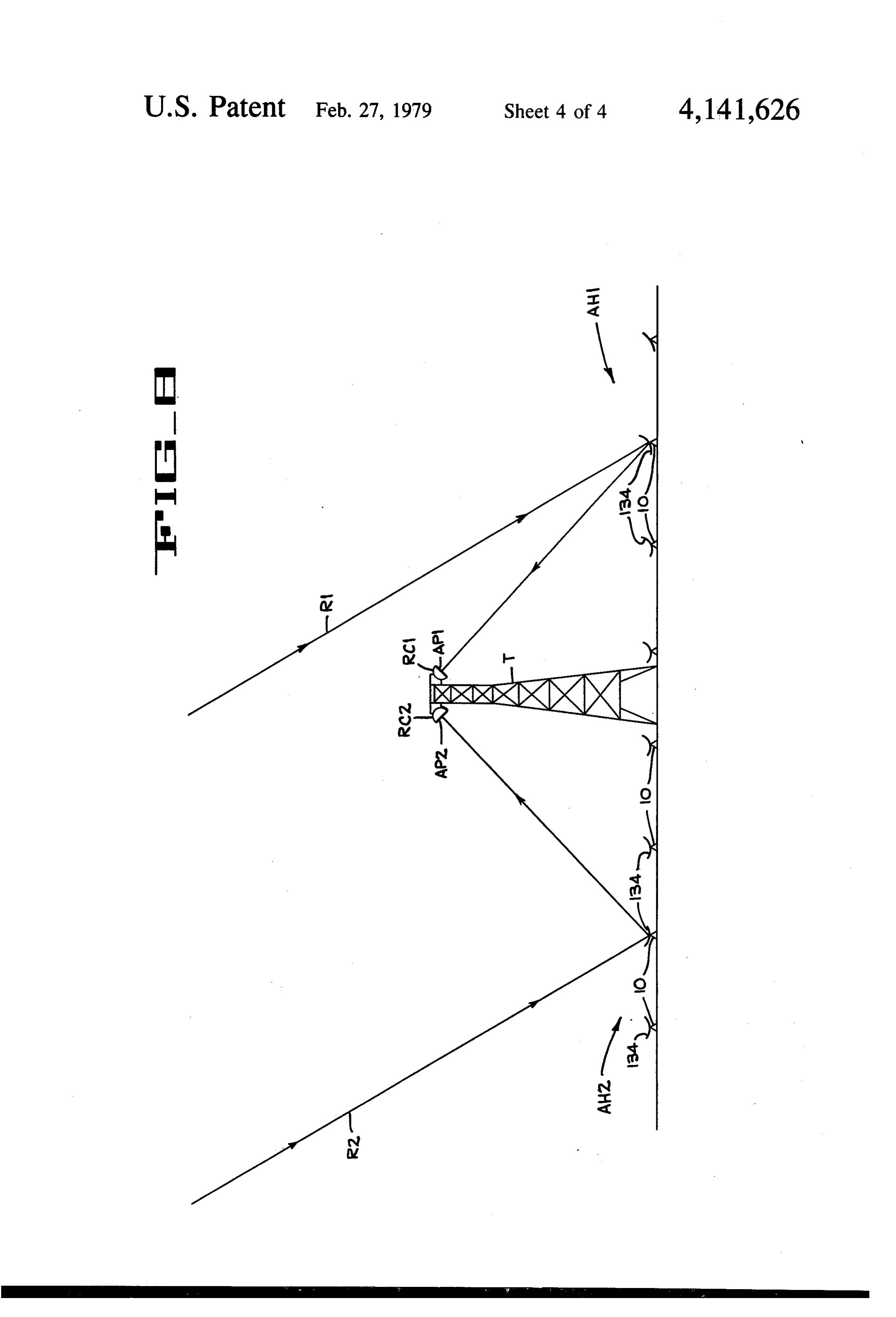
As diagrammatically illustrated in FIG. 8, a preferred cused for maximum concentration only at one or two application for the heliostat 10 of the present invention times of the day when the off-axis angle of incident is in a line type of solar-thermal central receiver system radiation is equal to the off-axis angle for which the which includes a tower structure T and a pair of receiv fixed heliostat curvature is designed. At such time or ers RC1 and RC2 mounted on the top of the tower times of day the reflected light will generally converge structure. Examples of such line type receivers are at a focal line which lies in the plane of the aperture. found in the prior art and are well known to those However, as the off-axis angle between the incident skilled in the art. The tower T and receivers RC1 and radiation and the normal plane of the fixed curvature RC2 are elongated and are preferably oriented with the reflecting surface changes, the reflected radiation will longitudinal axes extending in an east-west direction. 10 generally converge at a focal line which is displaced The receivers RC1 and RC2 have elongate apertures from the aperture plane, thereby causing an undesirable AP1 and AP2, respectively. The receivers are oriented dispersion of the reflected radiation. such that their apertures are outwardly tilted from the In contrast, the curvature of the reflecting surface vertical at approximately 45° angles. A first array AH1 134 of the heliostat of the present invention is variable of heliostats 10 is arranged on the north side of the 15 with the rotation thereof to maintain accurate concen tower T to concentrate solar radiation on the associated tration of sunlight on the respective apertures AP1 and north receiver RC1. A second array AH2 of heliostats AP2 (FIG. 8) throughout the day. As the angle between 10 is arranged on the south side of the receiver RC2. the incident radiation and the normal plane changes The heliostats 10 in each of the arrays AH1 and AH2 during the day, the radius of curvature of each heliostat are also oriented in an east-west direction. Referring to 20 is changed to maintain accurate focusing without any FIGS. 3 and 8, this means, of course, that the axes of off-axis astigmatism, i.e., to maintain the focal line of the rotation R-R of the heliostats 10 are parallel to the cylindrical reflecting surface 134 in the plane of the apertures of the receivers RC1 and RC2. The heliostats respective receiver aperture throughout the day. 10 are shown to be uniformly spaced in the north-south FIG. 9 graphically illustrates the relationships be direction; in practice, the heliostats are spaced such 25 tween the amount of concave curvatures of the reflect that, at a selected time, each array presents a continuous ing surfaces 134 of the several heliostats in the north mirror surface to the sun, with no shading of any re array AH1 of heliostats. It is assumed that the aperture flecting surfaces. As generally indicated in FIG. 8, the AP1 is 1.22 meters wide, that the mirrors are 3.05 me reflecting surface 134 of each heliostat 10 is rotated ters wide, that the heliostats are situated at a latitude of about the heliostat's axis of rotation to an angle of incli 30 35 north, and that the day of the year is winter solstice. nation adapted to direct the radiation incident thereon Curves are generated in FIG. 9 for heliostats which are generally into the associated aperture AP1 or AP2. As spaced at 0, 40, 80, and 120 meters from the aperture, also shown in FIG.8 with reference to sun rays R1 and with such distances being measured horizontally be R2, the third heliostat in the north array AH1 is rela tween a vertical plane through the center of the respec tively steeply inclined to direct the incident radiation 35 tive aperture and the axes of rotation R-R of the four (represented by the ray R1) back toward the aperture heliostats. The coordinates of the graph of FIG. 9 are AP1 of the receiver RC1. The third heliostat in the the time of day and the chordal height of the reflecting south array AH2 is slightly inclined, in the opposite surface 134. Chordal height is the distance, measured in direction from vertical relative to the direction of incli normal plane of the cylindrical surface 134, between the nation of the aforementioned heliostat, to direct the bottom center of the reflecing surface and a plane incident radiation (represented by ray R2) to the aper through the longitudinally extending ends of the reflect ture AP2 of the receiver RC2. ing surface.
As previously discussed, the mirror elements 130 of It should be noted that FIG. 9 indicates that the re each heliostat are bowed generally simultaneously to flecting surfaces of the four heliostats in the north array form a composite cylindrical reflecting surface 134 45 AH1 undergo about a two-fold or greater increase in having a generally circular cross-section in the trans chordal height from the start to the middle of a solar verse plane of the reflecting surface (i.e., the transverse day. This variation is especially great due to the large plane being perpendicular to the longitudinally extend variation in the off-axis angles of the incident radiation ing normal plane of the cylindrical reflecting surface at the solstices. During other days of the year the 134). The radius of curvature of each of the reflecting 50 change in curvature of the reflecting surfaces will not surfaces 134 of the heliostats 10 of each array is selected be as great. At the equinoxes, the curvatures of the according to the distance between the reflecting surface respective mirrors will remain constant, and thus only 134 of the particular heliostat and the plane of the asso dependent on their respective distances from the associ ciated aperture and the off-axis angle of the incident. ated aperture AP1, since during these days the off-axis radiation. The off-axis angle is the angle between the 55 angle of the sun remains constant. line projecting in the transverse plane of the reflecting Although the best mode contemplated for carrying surface of an incident ray and the mirror normal plane. out the present invention has been herein shown and As previously indicated, prior art central receiver described, it will be apparent that modification and systems have generally employed heliostats having up variation may be made without departing from what is wardly concave reflective surfaces which have se 60 regarded to be the subject matter of the invention. lected, but fixed, curvatures and which are rotated to What is claimed is:
different angles of inclination to track the apparent 1. An apparatus for concentrating solar radiation into diurnal movement of the sun. The fixed curvatures of an elongate aperture of an elongate solar receiver com the reflecting surfaces of the prior art heliostats will prising: a first frame; a second frame mounted to said result in off-axis astigmatism. For example, if one were 65 first frame for rotation about a single fixed axis, said first to assume that the reflecting surfaces 134 of the helio frame being oriented such that said fixed axis of rotation stats 10 have fixed (rather than variable) cylindrical of said second frame is parallel to the elongate aperture curvatures, the incident solar radiation would be fo of an elongate solar receiver; means defining a flexible,
Page 11
rectangular reflecting surface; resilient means for projections at the ends thereof which are pivotally mounting said reflecting surface means to said second mounted to said frame.
frame such that said reflecting surface means is parallel 7. The apparatus according to claim 4 wherein said to said axis of rotation; means for rotating said second means for bowing said resilient beams comprises a cam frame to change the inclination angle of the reflecting rod extending transversely of said beams and opera surface means and to thereby track the sun during the tively engaging said beams at the centers thereof for apparent diurnal movement of the sun; and means, oper deflecting the centers of said beams toward said frame; atively connected to said resilient mounting means, for and means for linearly moving said cam rod to force bending said reflecting surface means into a cylindrical said beam centers toward said frame. trough having a variable curvature in a plane normal to 10 8. The apparatus according to claim 7 wherein said said axis of rotation, said bending means including cam rod has wedge-shaped cam elements affixed to the motor driven means for changing said curvature sub lower surfaces thereof for respectively registering with stantially simultaneously with the rotation of said sec portions of said resilient beams.
ond frame to accurately focus incident solar radiation 9. The apparatus according to claim 4 further com into said aperture of the receiver at the various inclina 15 prising means for selectively disengaging said beam tion angles of the reflecting surface means and at the bowing means to permit said beams to achieve configu rations wherein said cylindrical reflective surface is various off-axis angles of the incident solar radiation slightly relative to a plane which is normal to said fixed axis of upwardly convex.
rotation of the member. 10. A system for collecting solar radiation comprising 2. The apparatus according to claim 1 wherein said 20 a solar receiver having an elongate aperture for receiv means defining a flexible, rectangular reflecting surface ing reflected solar radiation; a plurality of heliostats includes a plurality of flat mirrors; said resilient means side of thein solar disposed spaced parallel relationships at at least one receiver, with each of said heliostats for mounting said mirrors to said second frame includes comprising a frame, means for rotating said frame about a plurality of resilient beams, means for mounting said beams to said second frame in spaced, parallel relation 25 aturesingle fixed axis which extends parallel to said aper of said receiver, a flexible rectangular reflecting ships, and means for securing said mirrors between member adjacent beams; and said means for bending said reflect said frame,connected and means at a pair of opposite end edges to connected to said reflective mem ing surface into a cylindrical trough is operatively con ber for bending said member into a cylindrical trough nected to said beams and causes said beams to bend in 30 having a variable curvature unison, whereby said mirrors secured between said fixed axis, said bending means including in a plane normal to said beams are each deformed into a desired common cylin means for changing said curvature substantially motor driven drical curvature. simulta neously with the rotation of the reflecting 3. The apparatus according to claim 2 wherein each accordance with the distance between each respective member in of said resilient beams is constructed from sheet material 35 reflecting member and the off-axis angle of the incident having a longitudinally varying cross-section, said radiation relative said normal plane; and means for con bending means is operatively connected to the centers currently operating said means for rotating each of said of said beams; and the longitudinally varying cross-sec frames and said motor tion of the beams is adapted to cause each beam to curvature of each of saiddriven means for changing the reflecting members, said oper deform into a selected curvature when the center of the ating means being operatively connected to the rotating beam is deflected by said bending means. means and bending means of all of the heliostats to 4. An apparatus for focusing solar radiation on an adjust the inclination angles and amounts of elongate target such as an aperture of an elongate heat of the reflecting members of all of the heliostatscurvature substan receiver, said apparatus comprising: at least one flat tially simultaneously so as to accurately focus solar rectangular mirror member; a frame; means for mount 45 radiation into said receiver aperture during various ing said mirror member to said frame to form a cylindri different times of the day.
cal reflecting surface which has a variable curvature 11. A method of collecting sunlight on an elongate and is parallel to the elongate target upon which inci solar receiver comprising the steps of providing several dent solar radiation is to be concentrated, said mounting reflecting members; mounting the reflecting members means including a pair of parallel resilient beams which 50 for rotation about transversely spaced, fixed axes which are pivotally connected at their ends to said frame, are parallel to the elongate receiver; concurrently rotat means attached to said beams for securing said mirror ing the reflecting members throughout the solar day to member between said beams, each of said beams having generally continuously direct the sunlight incident upon an identical longitudinally varying configuration the several reflecting members toward the receiver; and adapted to bow said mirror securing means attached 55 substantially simultaneously with the rotation of each of thereto into varying cylindrical curvatures, and means the reflecting members, bending each of the several operatively connected to said beams for simultaneously reflecting members into various different cylindrical bowing said beams and thus said mirror member into curvatures, with the curvatures of the respective re said various desired cylindrical curvatures; and means flecting members being set in accordance with the off. for rotating said frame about an axis parallel to said axis angle between the incident sunlight and a plane elongate target. which is normal to said fixed axes of rotation of said 5. The apparatus according to claim 4 wherein each reflecting members and also in accordance with the of said resilient beams is made from sheet material, and particular distances between the respective reflecting each beam has a generally straight upper edge and a members and the receiver, whereby sunlight is accu curved lower edge. 65 rately focused by each and every reflecting member 6. The apparatus according to claim 5 wherein each onto the receiver without off-axis astigmatism. of said resilient beams have downwardly depending 32 k k k
Page 12
UNITED STATES PATENT AND TRADEMARK OFFICE
CERTIFICATE OF CORRECTION
INVENTOR(S) : WILLIAM J. TREYTL ARTHUR J. SLEMMONS
GERRY B. ANDEEN
It is Certified that error appears in the above-identified patent and that said Letters Patent is hereby Corrected as shown below:
In Column l of the patent specification, immediately following the heading "Background of the Invention" insert:
The Government has rights in this invention pursuant to Contract No. DE-AC03-76ET 204.26 awarded by the U. S. Department of Energy.
signed and sealed this
SEAL
Eighth Day of March 1983
Attest:
GERALD J. MOSSINGHOFF
Attesting Officer Commissioner of Patents and Trademarks

Provenance
- Collection
- Cited prior art
- Original PDF
- patentimages.storage.googleapis.com →
- Filed
- 1977-05-31
- Pages
- 12
- Method
- pdftotext (the PDF's own text layer) + pdftoppm 300dpi page scans
- Source
- Google Patents bibliographic record
- Granted
- 1979-02-27
- Inventors
- William J. Treytl; Arthur J. Slemmons; Gerry B. Andeen; FMC Corp
- Transcribed from
- patentimages.storage.googleapis.com →