patent · US3245892
Method for ultrasonically activating chemical reactions requiring the presence of a catalyst
12 April 1966
Page 1
April 12, 1966 J. B. JONES 3,245,892
METHOD FOR ULTRASONICALLY ACTIVATING CHEMICAL REACTIONS
REQUIRING THE PRESENCE OF A CATALYST
Filed Sept. 4, l960 2 Sheets-Sheet l Afg. /
SaaS
JAMES BYRON JONES
ATTORNEY
Page 2
April 12, 1966 J. B. JONES 3,245,892 METHOD FOR ULTRASONICALLY ACTivAFING CHEMICAL REACTIONS
REQUIRING THE PRESENCE OF A CATALYST
Filed Sept. 14, le60 2 Sheets-Sheet 2 Afg. 3
INVENTOR.
JAMES BYRON JONES
Page 3
United States Patent Office Patented Apr. 12, 1966
3.245,892 design. In place of nickel, other magnetostrictive mate
METHOD FOR ULTRAS6NCALLY ACTIVATING
CHEMICAL REACTIONS REQUIRING THE PRES
rials such as the alloy Permendur (an iron-cobalt alloy) or nickel-iron alloys, or alfanol (an aluminum-iron alloy),
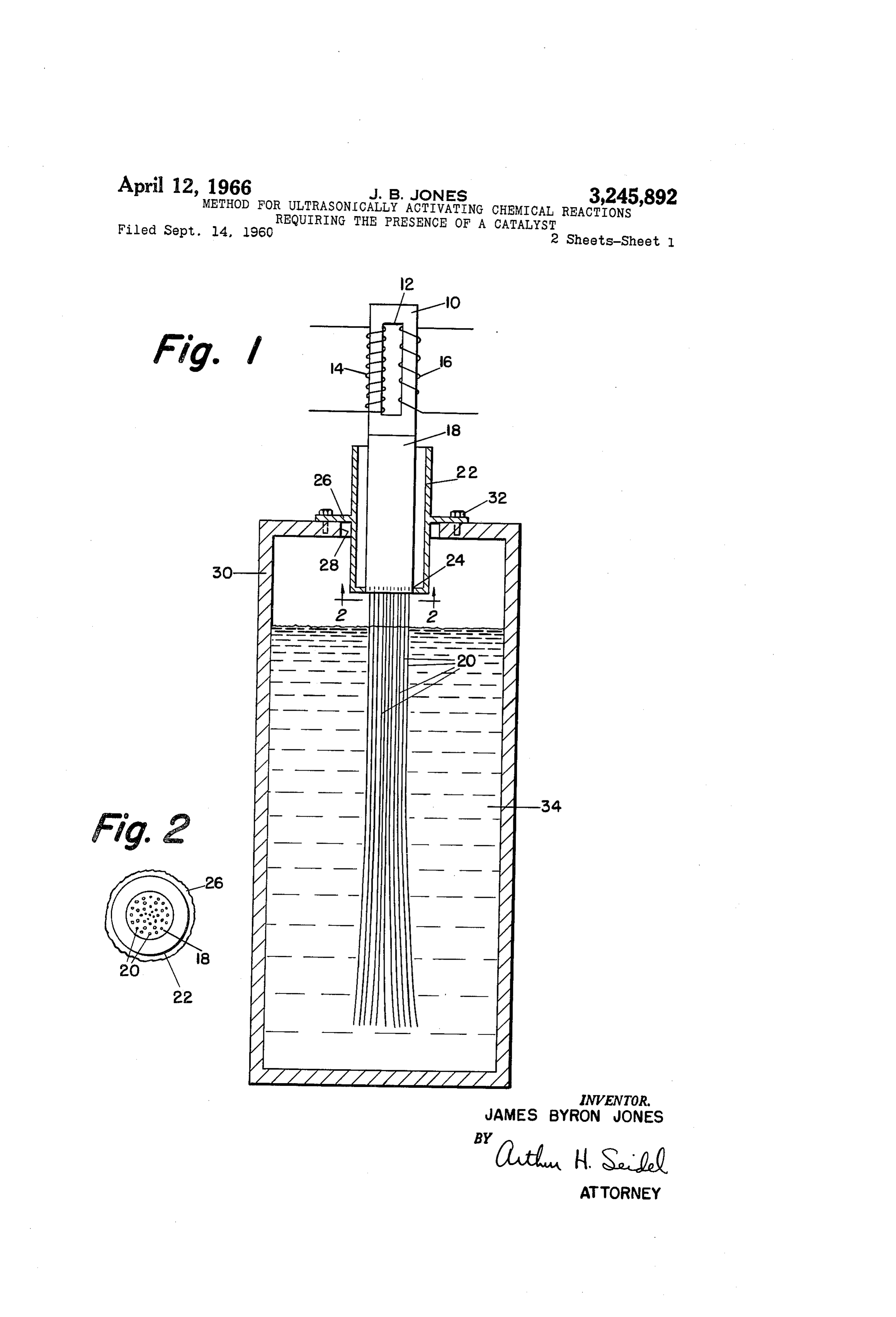
ENCE OF A CATALYST may be utilized. A wide variety of magnetostrictive trans James Byron Jones, West Chester, Pa. ducers are known to those skilled in the art and the con Filed Sept. 14, 1960, Ser. No. 56,020 struction of the transducer need not be described in de -- 2 Claims. (CI. 204-154) tail. The magnetostrictive transducer 10 is provided with The present application is a continuation-in-part of my a rectangular opening 12. A polarizing coil 14 and an excitation coil 16 are wound through the opening 12 copending application Serial No. 582,147 entitled Ultra 10 within sonic Tool, filed May 2, 1956, now U.S. Patent No. ly polarizing the transducer 10. The desirability of magnetical 3,029,766, issued April 17, 1962. the transducer 10 by means of the polariz This invention relates to an ultrasonic catalyst. More ing coil 14 in order for the metal laminations in the trans particularly, the present invention relates to an apparatuS ducer 10 to efficiently convert the applied R.F. energy and method for ultrasonically activating chemical reac 5 from the excitation coil 16 into vibratory energy will be tions requiring the presence of a catalyst. readily understood by those skilled in the art. A catalyst is any substance whose presence changes the While the magnetostrictive transducer 10 is sometimes rate of a chemical reaction without itself undergoing per preferred, it will be obvious to those skilled in the art that manent change in its composition. Catalysts may be other elastic vibratory energy means may be substituted used to accelerate or retard the chemical reaction. Most 20 therefor. For example, the piezoelectric ceramics such inorganic catalysts are metals and metal oxides. Catalyti inas place barium titanate and lead titanate-Zirconate can be used of the magnetostrictive transducer 10.
cal effects surface phenomena. Ultrasonic catalysts produce surface effects and greatly enhance the catalytic A coupler bar 18 of metal, such as stainless steel, is reaction if the surface area of the catalyst is increased. joined in axial end-to-end contact with the magnetostric Heretofore, it has been impractical to excite a large Sur 25 tive transducer 10. The end-to-end contact may be achieved by brazing, welding, or the like. A plurality of face area of a catalyst.
I have found that the provision of a plurality of fine sockets are provided on the end of the coupler bar 18. A wires joined to the end of an ultrasonic coupler results in plurality of wires 20 are secured in the sockets in the the provision of many feet of surface of the wires which coupler bar 18 with the uppermost tip portion of each become ultrasonic radiators when immersed in a gas, wire brazed, welded or soldered within one of the sockets. liquid, or semi-liquid. The effect thereof is to enhance 30 As used hereinafter the joint between the wires 20 and the catalytic action, thereby increasing or decreasing the the coupler bar 18 may be referred to as a fused metal joint. The wires 20 may be any one of a plurality of time element, and also reduce the amount of catalyst re catalysts.
quired for a particular chemical reaction. The catalyst Alternatively, the surface of the wires 20 may may be the wires themselves or may be a porous coating 35 be coated with a porous catalyst. The wires 20 may have on the wires. By immersing substantially the entire length physical characteristics of flexibility permitting them to of the wires in the fluid, substantially the entire length of be bent or curved by digital manipulation so as to remain the wires are utilized as a catalyst. spaced from one another.
It is an object of the present invention to provide a The over-all cumulative length of the coupler bar 18 novel ultrasonic catalyst. and each of the wires 20 is preferably but not necessarily It is another object of the present invention to provide 40 equal to an even number of one-quarter wavelengths ac an ultrasonic catalyst having a plurality of flexible vibra cording to the properties of the metal forming the coupler tion-transmitting members emanating from a single trans bar 18 and the wires 20 at its applied frequency of opera ducer. tion. It is, of course, not necessary that each of the wires It is another object of the present invention to provide 20 be of the same length.
a novel ultrasonically excited catalyst capable of effecting A force insensitive hermetically sealable mount is pro a chemical reaction within a container without transmit vided for the coupler bar 18 for a purpose to be described ting any appreciable amount of ultrasonic energy to the hereinafter. The mount comprises a shell 22 rigidly se container. cured at one end to the coupler bar 18. The shell 22 is It is still another object of the present invention to 50 Secured to the coupler bar 18 at point 24 while the other provide a novel ultrasonically excited catalyst capable of end of the shell 22 is free from attachment to the coupler effecting a chemical reaction within a continuous process. bar 18. An annular flange 26 is provided on the shell 22 Other objects will appear hereinafter. midway between the ends of the shell 22. For the purpose of illustrating the invention there is The shell 22 is cylindrical and has a length equal to shown in the drawings a form which is presently preferred; 55 at least a single one-half wavelength according to the it being understood, however, that this invention is not metal used for the shell at the applied frequency. The limited to the precise arrangements and instrumentalities shell 22 may have a length of but a single one-half wave shown. - length or may have a length of a plurality of one-half FIGURE 1 is a cross-sectional view of the ultrasonic wavelengths. The flange 26 is positioned at the node catalyst of the present invention disposed within a fluid 60 one-quarter wavelength or odd number multiples thereof. containing tank. from the free end of the shell 22. The thickness of flange FIGURE 2 is a cross-sectional view taken along lines 26 is not critical, however it should be relatively thin. 2-2 in FIGURE 1. As a general rule, the thickness of flange 26 should be the FIGURE 3 is a cross-sectional view of another em minimum consonant with securing desired strength chara bodiment wherein an ultrasonic catalyst is disposed with 65 acteristics. . . . . . .
in a pipe of a continuous process. - - The attachment point 24 between the shell 22 and the Referring to the drawing in detail, wherein like nu coupler bar 18 should be at a point of minimum stress, merals indicate like elements, there is shown in FIGURE 1 that is an anti-node or loop. Since the shell 22 is joined a transducer 10. to the coupler bar 18 at an anti-node or loop, and since The transducer 10 is preferably a magnetostrictive 70 the flange 26 is provided at a node, the mount for the transducer which may comprise a nickel stack of known coupler bar 18 is hermetically sealable and force-insen
Page 4
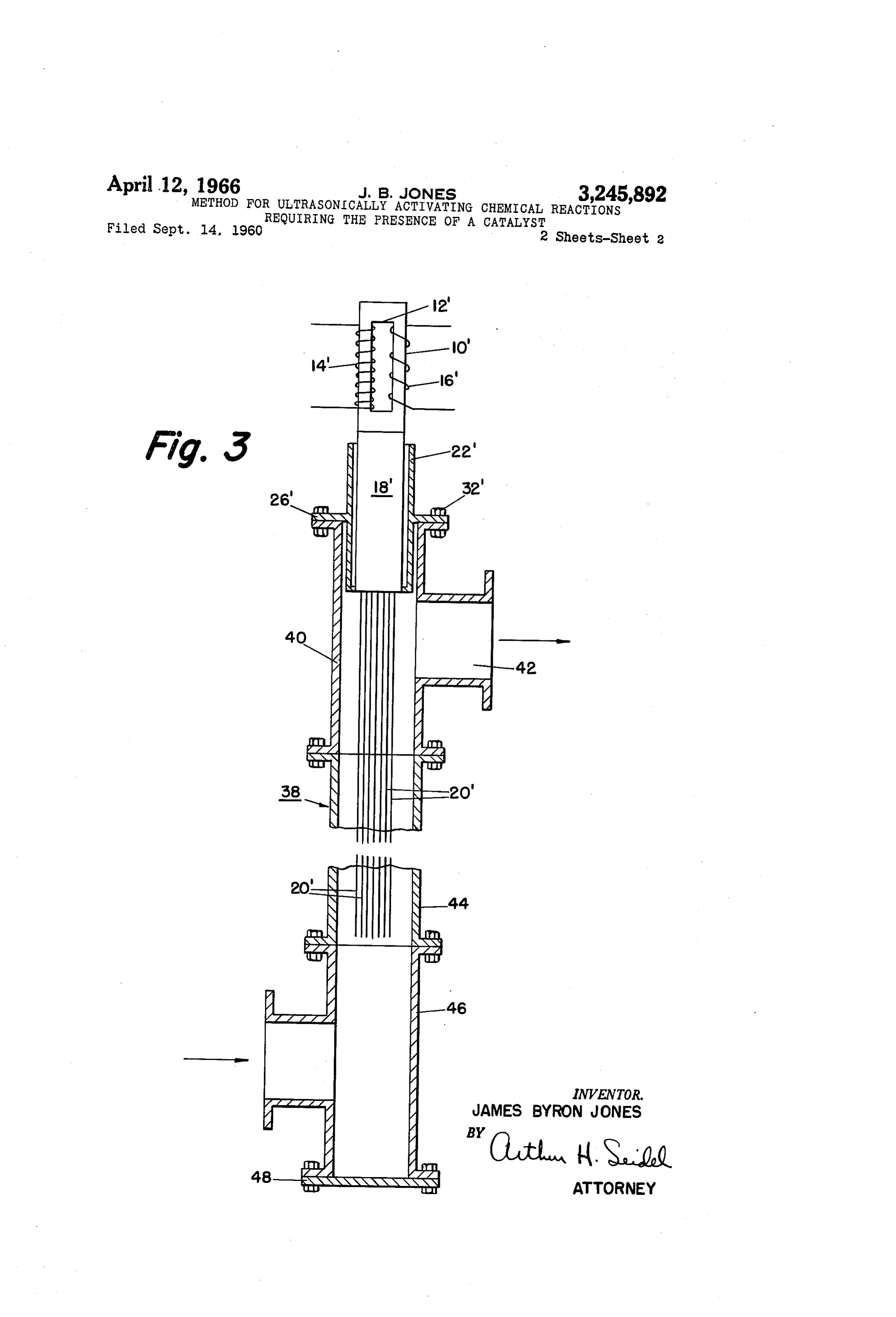
sitive. Thus, no appreciable vibratory energy will be The ultrasonically excited catalyst in FIGURE 3 is transmitted to the tank 30. The tank 30 is provided with identical with the catalyst shown in FIGURE 1. There an opening 28 through which extends the lower portion fore, the corresponding elements in FIGURE 3 are shown of the shell 22, the coupler bar 18, and the wires 20. The with primed numerals.
tank 30 and the flange 26 are fixedly secured, by any con The ultrasonically excited catalyst in FIGURE 3 is ventional means such as bolts 32, so as to provide a her capable of effecting a chemical reaction in a portion 38 metic seal. of a continuous process. The portion 38 includes a T The tank 30 contains the fluid 34 which is undergoing coupling 40 having an outlet port 42, a pipe 44 having a chemical reaction. The fluid 34 may be a gas, liquid, one end threaded to one of the arms of the T-coupling or semi-liquid. Substantially the entire length of the wires 0. 40, and a T-coupling 46 threaded to the other end of 20 are in contact with the fluid 34. The wires 20 are the pipe 44. The shell 22' is hermetically sealed to the axially disposed with relation to the longitudinal axis of other arm of the T-coupling 40 by bolts 32". The wires the coupler bar 18, therefore the mechanical vibrations of 20' extend axially from the coupler bar 18' through the the coupler bar 18 will cause longitudinal vibrations in the T-coupling 40 into the pipe 44 so that substantially the wires 20. Therefore, substantially the entire length of 5 entire length of the wires 20' is exposed to the moving the wires 20 will act as an ultrasonic radiator. fluid.
The operative range of vibratory frequencies of the The T-coupling 46 is provided with a removable cap transducer 10 may include frequencies within the range 48. If the rate of flow of the fluid through the portion 38 59 to 800,000 cycles per second, with the preferred range is very high, it may be necessary to remove the cap 48 constituting 500 to 300,000 cycles per second. This pre 20 and mount a second ultrasonically excited catalyst on ferred range of operating frequencies may be readily the T-coupling 46. The second catalyst would be mount achieved by transducer elements of known design, which ed on the T-coupling 46 in the same manner as the first are capable of generating elastic vibratory energy of high catalyst is mounted on coupling 40 with the wires of the intensity. catalysts extending into pipe 44 toward each other. The wires 20 may be the catalyst or may be coated with 25 The apparatus in FIGURE 3 operates in the same man particles of a porous catalytic material. In certain re ner as the apparatus shown in FIGURE 1. The fluid of actions, it is necessary for the catalyst to have a high a continuous process flows through the portion 38 in the temperature. The temperature of the coupler bar and direction of the arrows shown in FIGURE 3. If desired, the wires 20 may be elevated in any conventional manner. the direction of flow may be reversed. In either case, it The present invention may be utilized to accomplish, 30 is to be noted that the wires 20' vibrate in a direction par enhance or retard any one of a plurality of chemical re allel to the direction of flow. actions. For example, a hot platinum wire in a gaseous Alternatively, the wires 20 and 20 may take the form mixture of oxygen and hydrogen results in water; a fer of perforated tubes thereby providing an inner and outer rous wire in hydrogen and nitrogen results in NH3; a hot surface for contact with the fluids undergoing a chemical platinum wire in alcohol results in acetic acid; a platinum 35 reaction. In this manner, the rate of the action and the or gold wire in hydrogen peroxide causes a decomposi amount of catalyst necessary may be reduced even fur tion into oxygen and hydrogen; a copper or silver wire in ther. Hereinafter, the wires 20 and 20' may be referred methanol results in formaldehyde; a nickel, cobalt or iron to as flexible elongated vibrating members. Also, the wire in methane and water results in carbon monoxide and transducers 10 and 10' may be referred to as a vibra hydrogen; a copper, silver or platinum wire in carbon 40 tion-generating means.
monoxide and hydrogen results in methyl alcohol. The present invention may be embodied in other specific Also, an iron, copper or nickel wire can be used in forms without departing from the spirit or essential at the cracking of hydrocarbons to carbon and hydrogen; a tributes thereof and, accordingly, reference should be copper, silver or nickel wire can be used in the dehydro made to the appended claims, rather than to the foregoing genation of alcohols to aldehydes or ketones; a copper, 45 Specification as indicating the scope of the invention. iron or nickel wire in CH2 results in cuprene and poly I claim:
mers; an iron wire can be used to form cyanide from 1. A method of catalytically effecting a chemical re NaCO3, C and N2; a nickel wire in liquid fats and hy action in a fluid which comprises the steps of immersing drogen results in solid fats; a copper or manganese oxide Substantially the entire length of a plurality of elongated wire in carbon monoxide and oxygen results in carbon 50 members in the fluid, with each of said elongated mem dioxide; a platinum wire in ammonia and oxygen results bers having a catalyst on its surface, and catalytically ef in nitric acid; and platinum or vanadium wire oxide in fecting a chemical reaction in the fluid by mechanically sulfur dioxide and oxygen results in sulfur trioxide. ultrasonically vibrating said elongated members. The present invention is utilized in the following man 2. A method in accordance with claim 1 in which le: the fluid is continuously moved past the vibrating mem The tank 30 is substantially filled with the fluids 34 bers.
to be treated or chemically reacted. The flange 26 on References Cited by the Examiner the shell 22 is rigidly secured to the tank 30 by the bolts 32 with the wires 20 substantially immersed within the UNITED STATES PATENTS fluid 34. The vibratory energy generated by the trans 60 1939,712 12/1933 Mahoux ------------ 204-154 ducer 10 is transmitted to the wires 20. The wires 20 act 2,096,011 10/1937 Smith -------------- 204-37 as an ultrasonic catalyst to the chemical reaction taking 2,500,008 3/1950. Richardson --------- 204-193 place within the tank 30. Alternatively, the wires 20 may 2,633,477 3/1953 Rollman --------- 23-288 X be coated with a plated, porous, film-like catalyst. The 2,742,408 4/1956 La Porte -------- 204-154 ultrasonic vibrations of the wires 20 increase the rate of 65 3,029,766 4/1962 Jones -------------- 204-154 the catalytic effect and reduce the amount of catalyst re quired for a particular chemical reaction. JOHN H. MACK, Primary Examiner.
FIGURE 3 discloses another embodiment of the present JOHN R. SPECK, MURRAYTILLMAN, WINSTON A. invention which is particularly directed toward effecting chemical reactions in a continuous process as compared 70 DOUGLAS, Examiners.
with a batch-wise process as shown in FIGURE 1. H. S. WILLIAMS, Assistant Examiner.
Provenance
- Collection
- Cited prior art
- Original PDF
- patentimages.storage.googleapis.com →
- Filed
- 1960-09-14
- Pages
- 4
- Method
- pdftotext (the PDF's own text layer) + pdftoppm 300dpi page scans
- Source
- Google Patents bibliographic record
- Granted
- 1966-04-12
- Inventors
- Jones James Bryon
- Transcribed from
- patentimages.storage.googleapis.com →