patent · US20090322089A1
Integrated solar energy receiver-storage unit
31 December 2009
Page 1 — bibliographic record
(19) United States (12) Patent Application Publication (10) Pub. No.: US 2009/0322089 A1
Mills et al. (43) Pub. Date: Dec. 31, 2009 (54) INTEGRATED SOLAR ENERGY Publication Classification RECEIVER-STORAGE UNIT (51) Int. Cl.
(76) Inventors: David R. Mills, Palo Alto, CA Hg.A. CR (US); Peter K. Le Lievre, Palo ( .01)
Alto, CA (US) (52) U.S. Cl. ........................................... 290/52; 126/617 Correspondence Address: (57) ABSTRACT 9.ERSTER LLP Receivers for use in Solar energy collector systems and Solar PALOALTO, CA 94.304-1018 (US powered electrical energy generating plants are provided. The 9 (US) receivers comprise a Solar radiation absorbing core that con verts absorbed solar radiation to thermal energy. The core (21) Appl. No.: 12/157,064 comprises a refractory material to allow the receivers to oper 1-1. ate continuously at high temperatures reached by absorbing (22) Filed: Jun. 6, 2008 concentrated Solar radiation. The thermal energy so generated Related U.S. Application Data in the core may be stored in the receiver for a transitory .S. App period, or for a more extended period. Receivers may com (60) Provisional application No. 60/933,620, filed on Jun. prise one or more fluid channels in and/or around the core for 6, 2007, provisional application No. 60/933,619, filed conveying a working fluid to facilitate extraction of stored on Jun. 6, 2007. thermal energy from the core.
Page 2
Drawing sheet — no readable text.
Page 3
Drawing sheet — no readable text.
Page 4
Drawing sheet — no readable text.
Page 5
Drawing sheet — no readable text.
Page 6
Drawing sheet — no readable text.
Page 7
Drawing sheet — no readable text.
Page 8
US 2009/0322089 A1 Dec. 31, 2009
INTEGRATED SOLAR ENERGY ods. The first and second heat exchange fluids are then used RECEIVER-STORAGE UNIT alternately for heat exchange with a working fluid that is used to energize an associated heat engine.
CROSS REFERENCE TO RELATED 0006. Also of relevance to the present application is a APPLICATIONS thermal energy storage system as disclosed in International 0001. This application claims the benefit of priority from Patent publication WO2005/088218, by Larkden Pty Ltd, in U.S. Provisional Patent Application Ser. No. 60/933,620, which a substantially solid body of graphite is employed to entitled “Integrated Solar Energy Receiver-Storage Unit.” store heat energy for Subsequent release to a fluid through filed Jun. 6, 2007, which is hereby incorporated by reference Surface-mounted heat exchangers. However, in this system, herein in its entirety. This application is related to U.S. patent as disclosed, thermal energy is generated in the graphite body application Ser. No. entitled “Combined Cycle by electrical resistance heating in a cavity within the graphite body.
Power Plant, filed concurrently herewith, which claims the 0007. A need exists for improved receivers to be used with benefit of priority from U.S. Provisional Patent Application tower Solar arrays (e.g., a multi-tower Solar array), and in Ser. No. 60/933,619, entitled “Combined Cycle Power Plant.” particular, receivers that include integrated thermal energy filed Jun. 6, 2007, each of which is hereby incorporated by Storage.
reference in its entirety.
SUMMARY
FIELD
0002 This application relates to a receiver for a solar 0008. The present application describes receivers for use energy system, and in particular to an integrated Solar energy in Solar energy collector Systems and Solar-powered electrical receiver-thermal energy storage unit. The receivers and inte energy generating plants. In general, the receivers comprise a grated units disclosed here may be suitable for receiving Solar radiation absorbing core that converts absorbed solar concentrated solar radiation from a field of heliostat-type radiation to thermal energy. The core comprises a refractory reflectors. A receiver, e.g., an integrated receiver-thermal material to allow the receivers to operate continuously at high energy storage unit, in Some of its applications, may be temperatures reached by absorbing concentrated Solar radia employed as a tower-mounted receiver or elevated in some tion. The thermal energy so generated in the core may be other manner. In other applications, a receiver, e.g., an inte stored in the receiver for a transitory period, or for a more grated receiver-thermal energy storage unit, may be located extended period. Thus, a receiver may function as an inte elsewhere than on a tower, for example at or near ground grated receiver-thermal energy storage unit, and the terms level, e.g., when employed as a secondary receiver. “receiver” and “integrated receiver-thermal energy storage unit, and “integrated receiver-storage unit are used inter
BACKGROUND changeably herein. A working fluid, e.g., air, may be employed to extract stored thermal energy from the receivers.
0003 Tower-mounted receivers are well known in the 0009. Also disclosed herein are methods and systems context of Solar energy collector systems and may take Vari related to the receivers described in general terms above. For ous forms, depending upon whether they are employed, for example, methods for effecting heat exchange utilizing the example, in the transfer of radiative energy to photovoltaic receivers are disclosed here. In addition, various Solar energy cells or in the transfer of thermal energy to a heat exchange collector systems incorporating the receivers are also dis fluid Such as water, a molten salt or air. closed. Further, variations of solar-powered electrical energy 0004 More efficient tower-mounted receivers may incor generating plants using the receivers are described. porate a cavity having a relatively small aperture through 0010. The term “refractory material' is to be understood in which concentrated (reflected) radiation is focused from a the context of the present application as one that is Substan field of reflectors and, in receivers that have relevance to the tially opaque to Solar radiation and remains substantially present application, provision is made for the transporting of stable (physically and/or chemically) when exposed to tem thermal energy that is generated within the receiver as a peratures (for example of the order of about 800° C. to about consequence of absorption of Solar energy in the wall of the 2500° C., or about 800° C. to about 3000° C., e.g., at least cavity. However, these receivers do not make specific provi about 800° C., at least about 1000°C., at least about 1200°C., sion for integrated storage of thermal energy that is generated at least about 1400°C., at least about 1600° C., at least about in the receiver by absorption of Solar energy. 1800° C., at least about 2000° C., at least about 2200° C., or 0005. A solar energy receiver that does provide for inte at least about 2500°C.) that may be established with absorp grated thermal energy storage is disclosed in U.S. Pat. No. tion of concentrated solar radiation. Such “refractory mate 4,815,443, issued Mar. 28, 1989, and assigned to Rockwell rial” may, for example, comprise a refractory metal, a International Corporation (443 patent). However, the ceramic, a cermet, or any combination thereof. Refractory receiver as described in the 443 patent has specific applica materials may for example comprise alumina, silica, carbon, tion to a space station. There, the receiver comprises a first magnesia, Zirconia, silicon carbide, titanium carbide, tanta (helical-form) fluid conduit that is located within a cavity of lum carbide, chromium carbide, niobium carbide, Zirconium the receiver, and a second fluid conduit that is located within carbide, molybdenum disilicide, calcium oxide, graphite, a thermal energy storage layer that is formed from a metallic chromite, dolomite, magnesite, quartzite, aluminium silicate, material that surrounds the cavity. The first conduit and the tungsten, molybdenum, niobium, tantalum, rhenium, beryl thermal energy storage layer are both exposed to Solar radia lium, and combinations thereof.
tion that is focused into the cavity during insolation periods. 0011. As used herein, the terms “primarily’ and “major During these in-Sun periods, a first heat exchange fluid is part are meant to mean at least about 50%. Thus a receiver cycled through the first conduit. A second heat exchange fluid element that is composed primarily of a refractory material is cycled through the second conduit during in-shadow peri comprises at least about 50% by any measure (e.g., by weight
Page 9
US 2009/0322089 A1 Dec. 31, 2009
or volume) of that refractory material. The term "pipe' as magnesia, Zirconia, silicon carbide, titanium carbide, tanta used herein is meant to encompass any tube, conduit or the lum carbide, chromium carbide, niobium carbide, Zirconium like. Pipes may have any configuration, e.g., may have a carbide, molybdenum disilicide, calcium oxide, graphite, round cross-sectional shape, or a polygonal cross-sectional chromite, dolomite, magnesite, quartzite, aluminum silicate, shape, may be straight, bent, or curved, and may be joined to tungsten, molybdenum, niobium, tantalum, rhenium, beryl other pipes, Valves, end caps, junctions, vessels, and the like. lium, and combinations thereof.
A "pipe manifold' as used herein is meant to refer to an 0014. An incident surface of the core that is to receive and arrangement of multiple pipes, including any associated pipe absorb solar radiation directed through the receiver aperture joints, valves, end caps, junctions, and the like. A “receiver may have any Suitable orientation and configuration within body' and “body” refer to a portion of a receiver that com the receiver body. Thus, in some variations, an incident Sur prises a Solar radiation absorbing refractory material. In some face of the core may be substantially horizontal. An incident cases, the refractory material may be primarily contained in Surface of a core in certain receivers may be substantially or confined to a subportion of a body, e.g., an interior Subpor vertical. Some receiver core may comprise both substantially tion, which may be referred to herein as a “receiver core” or a horizontal and Substantially vertical incident Surfaces. A “core.” In other instances, the refractory material may not be receiver with an inclined aperture may also be inclined so as localized within the body (e.g., the body as a whole may to be approximately parallel to the receiver aperture comprise the refractory material), in which case the receiver 0015. Further, the bulk of the solar radiation absorbing body and the receiver core are synonymous. As used herein refractory core may have a variety of configurations. For “vertical and “horizontal are used in reference to ground. example, the core may comprise an exterior cladding layer, Further, descriptions such as “substantially horizontal.” “sub which may in some cases protect an interior portion of the stantially vertical.” “substantially opaque,” and “substantially refractory core underneath the cladding layer. Further, the one stable' and the like are meant to encompass the relevant or more passageways in the core may have a variety of properties and minor deviations therefrom, e.g., deviations of arrangements. For example, one or more passageways may be about 10%, or about 5% or less. Thus, a “substantially hori directed radially outward from an inner portion of the core to Zontal aperture may be generally parallel to ground, e.g., a peripheral portion of the core. In certain variations, the core within about +/-10 degrees or less, within about +/-8 may comprise an aggregated material, and the aggregated degrees, within about +/-5 degrees, within about +/-3 material may have a particle size and packed density Such that degrees, or within about +/-1 degree of a horizontal direction, the working fluid can permeate through passageways relative to ground. A material that remains “substantially between interstitial voids in the aggregate. Variations of cores stable' is one that is not exposed to conditions that would may comprise one or more metal structures, e.g., a mesh or degrade the material prematurely. For instance, a ceramic or fins, that may distribute heat through the core. other material would be substantially stable if maintained 0016. The aperture may be situated anywhere in the within normally accepted operating temperatures or below receiver, e.g., in a receiver housing or in the core itself. In the temperature at which e.g. spalling or other Surface and/or Some variations of receivers that are designed to be tower internal damage occurs. It should also be noted that the terms mounted, the aperture may be a substantially horizontally “a” “an and “the are meant to encompass singular as well as oriented aperture that is situated on a lower surface of the plural referents unless the context clearly indicates otherwise. receiver, so as to comprise a downward facing opening of the Numerical ranges as used herein are meant to be inclusive of receiver. Such an arrangement may reduce convective losses any endpoints indicated for the ranges, as well as any number through the aperture, and may eliminate the need for an included in the ranges. expensive quartz window, and also eliminate losses due to 0012 Some variations of the receivers comprise a core Such window. However, in certain variations, a window, e.g., composed primarily of a refractory material. The core is a quartz window, may cover or partially cover the aperture. configured to absorb solar radiation that has been directed 0017. In some variations, a displacement between the through an aperture in the receiver, so that the absorbed solar aperture through which Solar radiation is directed and the core radiation is converted to thermal energy stored in the core. may be adjusted to determine an energy density or intensity of The core also comprises one or more fluid passageways for the Solar radiation that is incident on the core. For example, conveying a working fluid through and/or around the core to the displacement between the aperture and the core may be facilitate extraction of stored thermal energy from the core. adjusted to increase an energy collection efficiency of the These receivers may be tower-mounted or mounted at or near receiver. In certain variations, a displacement between the ground level, e.g., for a solar array comprising a beam down aperture and the core may be selected to image an array of receiver configuration. The working fluid used with these reflectors that direct solar radiation through the aperture. receivers may for example comprise primarily air. 0018. Other types of receivers are disclosed herein. These 0013 The refractory material in a receiver may be any receivers are tower mounted. The receiver comprises a sub refractory material that is Substantially opaque to Solar radia stantially horizontally oriented aperture situated on a lower tion and remains Substantially stable when exposed to tem Surface of the body so as to comprise a downward facing peratures that are established with absorption of concentrated opening. The receivers also include a solar radiation absorb solar radiation. The refractory material may be selected from ing core that comprises a refractory material. The core is the group of refractory metals, ceramics, and cermets. Some disposed within the body and above the aperture so that solar of the refractory materials may be able to withstand continu radiation directed through the aperture is incident on the core ous operation attemperatures of at least about 1000°C., or at for bulk absorption in the core to generate stored thermal least about 1200°C., or even higher. The refractory material energy in the core. Some variations of these tower mounted in the receivers may comprise more than one refractory com receivers may comprise at least one passageway in and/or ponent. A refractory material used in a receiver may be around the core for conveying a working fluid, e.g., a working selected from the group consisting of alumina, silica, carbon, fluid that comprises primarily air, through and facilitating
Page 10
US 2009/0322089 A1 Dec. 31, 2009
extraction of thermal energy from the core. A window, e.g., a that the core reaches a continuous operating temperature of quartz, window, may but need not be used to at least partially about 1000° C. or higher, or about 1200° C., or even higher. cover the aperture. The working fluid used in these methods may for example 0019. The refractory core may have any suitable compo comprise primarily air.
sition. For example, in Some variations the core may be pri 0024. The methods may comprise passing a working fluid marily composed of a refractive material that is substantially through any one of a variety of configurations of passage opaque to Solar radiation and remains Substantially stable ways. For example, methods may comprise flowing the work when exposed to temperatures that are established with ing fluid through one or more passageways that are directed absorption of concentrated solar radiation. The refractory radially outward from an interior region of the core to a material may be selected from the group of refractory metals, peripheral region of the core, or one or more serpentine or ceramics, and cermets. The refractory materials may for helical passageways through the core. In certain methods, the example be able to withstand continuous operation at tem core may comprise an aggregate, and the methods may com peratures of at least about 1000°C., or at least about 1200°C., prise flowing the working fluid through one or more passage or even higher. The refractory material in these receivers may ways comprising interconnected interstitial spaces in the comprise more than one refractory component. aggregate.
0020. The core may have a variety of configurations. For example, in Some variations an incident Surface of the core 0025. These methods may be used in context of tower designed to receive and absorb incident Solar radiation may mounted receivers, or receivers mounted at or near ground be substantially horizontal. In other variations, an incident level, e.g., receivers in a solar array configured in a beam surface of the core may be substantially vertical. Further, a down arrangement. For either tower mounted or ground displacement between an incident Surface of the core may be mounted receivers, a cross-sectional dimension of an aperture adjusted, e.g., to adjust a Solar radiation energy density or and/or a displacement between the aperture and an incident intensity on the core, and/or to increase an energy collection Surface of the core may be adjusted, e.g., to adjust an energy efficiency of the receiver. In certain variations, a displacement density or intensity on a core and/or to increase a collection between the aperture and a substantially horizontal incident efficiency of the receiver. For example, the methods may Surface of the core may be selected to image or approximately comprise concentrating and directing the Solar radiation image an array of reflectors directing reflected Solar radiation through the aperture so that a point of maximum energy through the aperture. density or intensity occurs at or before the aperture, e.g., so 0021. The solar radiation absorbing core itself may have a that Solar radiation is relatively divergent and less intense as it variety of configurations, and may for example comprise an is incident on the core, alleviating local overheating. exterior cladding layer, which may in Some cases protect an 0026. In certain variations, the methods may comprise interior portion of the core underneath the cladding layer. directing the concentrated Solar radiation to be incident on a Further, if the core comprises one or more passageways con substantially horizontal surface of the core, or to be incident figured to convey a working fluid through and/or around the on a substantially vertical surface of the core, or to be incident core, those one or more passageways may have a variety of on both a substantially horizontal Surface and a Substantially arrangements. For example, one or more passageways may be vertical surface of the core. Certain ones of the methods may directed radially outward from an inner portion of the core to comprise imaging or approximately imaging an array of a peripheral portion of the core. The core may comprise an reflectors on a substantially horizontal incident surface of the aggregate, and one or more fluid passageways in the core may core, where the array of reflectors is used to direct solar comprise interconnected interstitial spaces between particles radiation through the aperture of the receiver to be incident on of the aggregate. Cores in some instances may comprise one that substantially horizontal core surface. or more metal structures, e.g., a mesh or fins, that in operation 0027. In the methods, any type of array of reflectors may may distribute heat through the core. be employed to direct concentrated Solar radiation through 0022. Other variations of receiver-storage units (receivers) the aperture to be incident on the core. For example, an array for use in a solar energy collector system are described here. comprising fixed horizontal axis and/or fixed vertical axis These receivers comprise a body having at least a major part heliostats may be used.
of its Volume composed of a refractory material, and a cavity 0028. Additional methods for effecting energy exchange provided within the body and having an aperture through are disclosed herein. These methods comprise directing con which concentrated Solar radiation is in use focused to centrated Solar radiation through a substantially horizontally impinge on a wall of the cavity, and at least one passageway oriented aperture in a lower portion of a body of a tower located within the body for conveying a working fluid through mounted receiver so that the Solar radiation is incident on and and facilitating extraction of thermal energy from the body. absorbed by a core disposed within the body to generate 0023 Methods for effecting energy exchange to generate thermal energy in the core. The methods further comprise thermal energy from Solar energy are also described here. transferring thermal energy from the core to a working fluid, Some variations of these methods comprise directing concen e.g., a working fluid that comprises primarily air. trated Solar radiation through a receiver aperture, so that the 0029. The methods may comprise transferring thermal Solar radiation is incident on a receiver core, where the core is energy from the core to the working fluid by flowing the composed primarily of a refractory material that is capable of working fluid through one or more fluid passageways in and/ absorbing Solar radiation to generate thermal energy. The or around the core. Such passageways may have a variety of methods further comprise transferring thermal energy from configurations. For example, one or more passageways may the core to a working fluid by passing the working fluid be directed radially between an internal portion of the core through one or more passageways in and/or around the core. and a peripheral region of the core, or through a serpentine The methods may comprise directing concentrated Solar passageway through the core. In some variations, the core radiation through the aperture to be incident on the core so may comprise an aggregate, and the methods may include
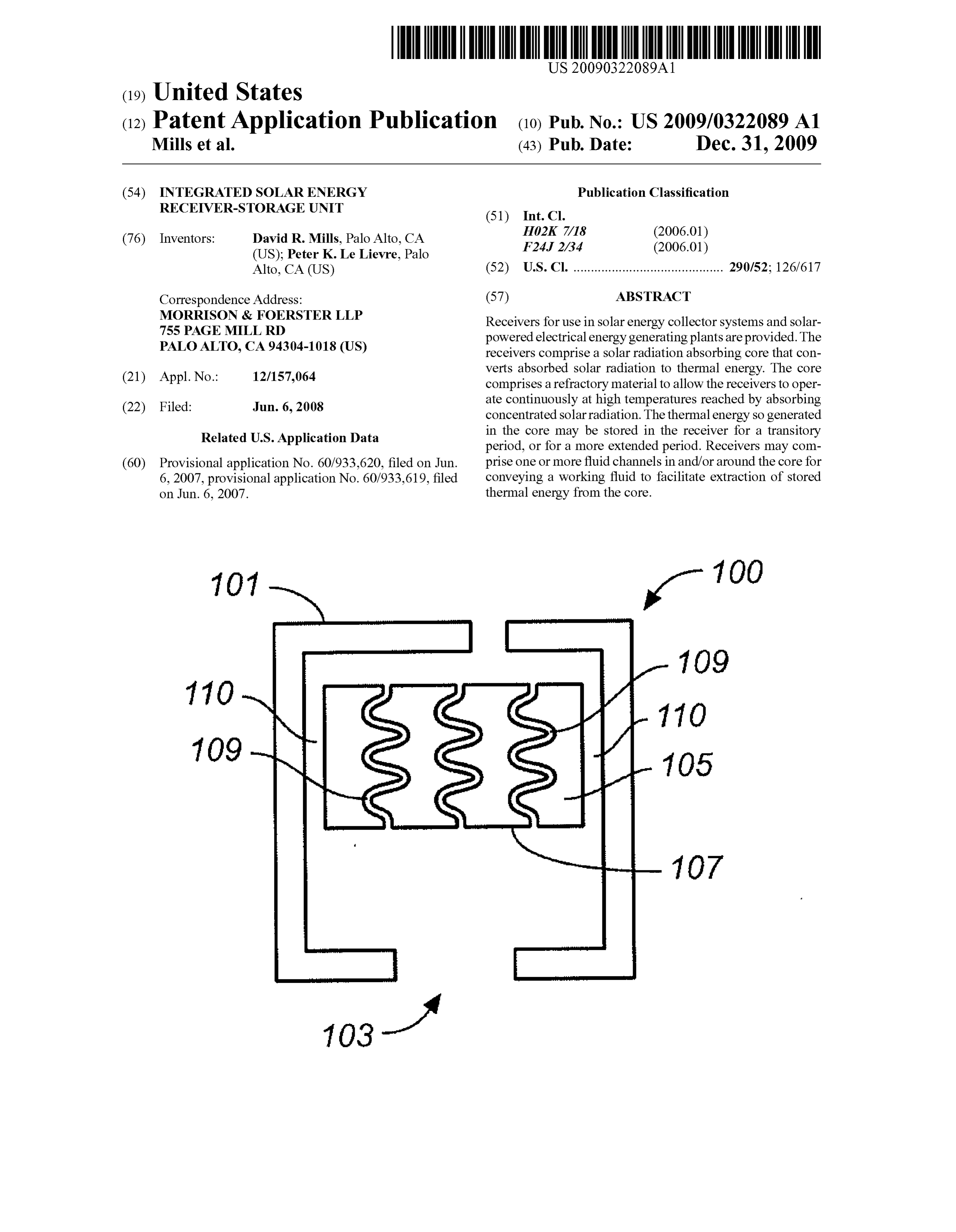
Page 11
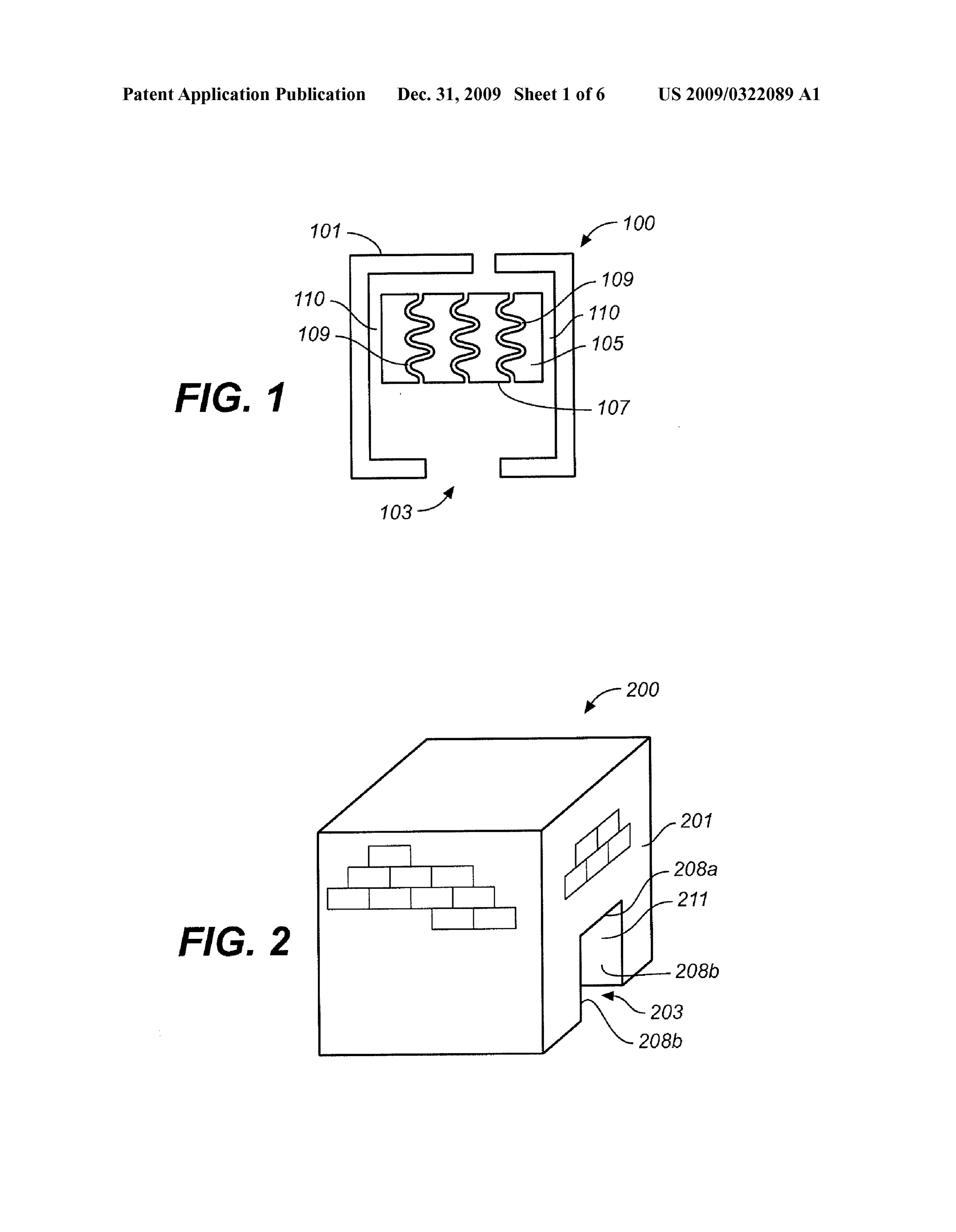
US 2009/0322089 A1 Dec. 31, 2009
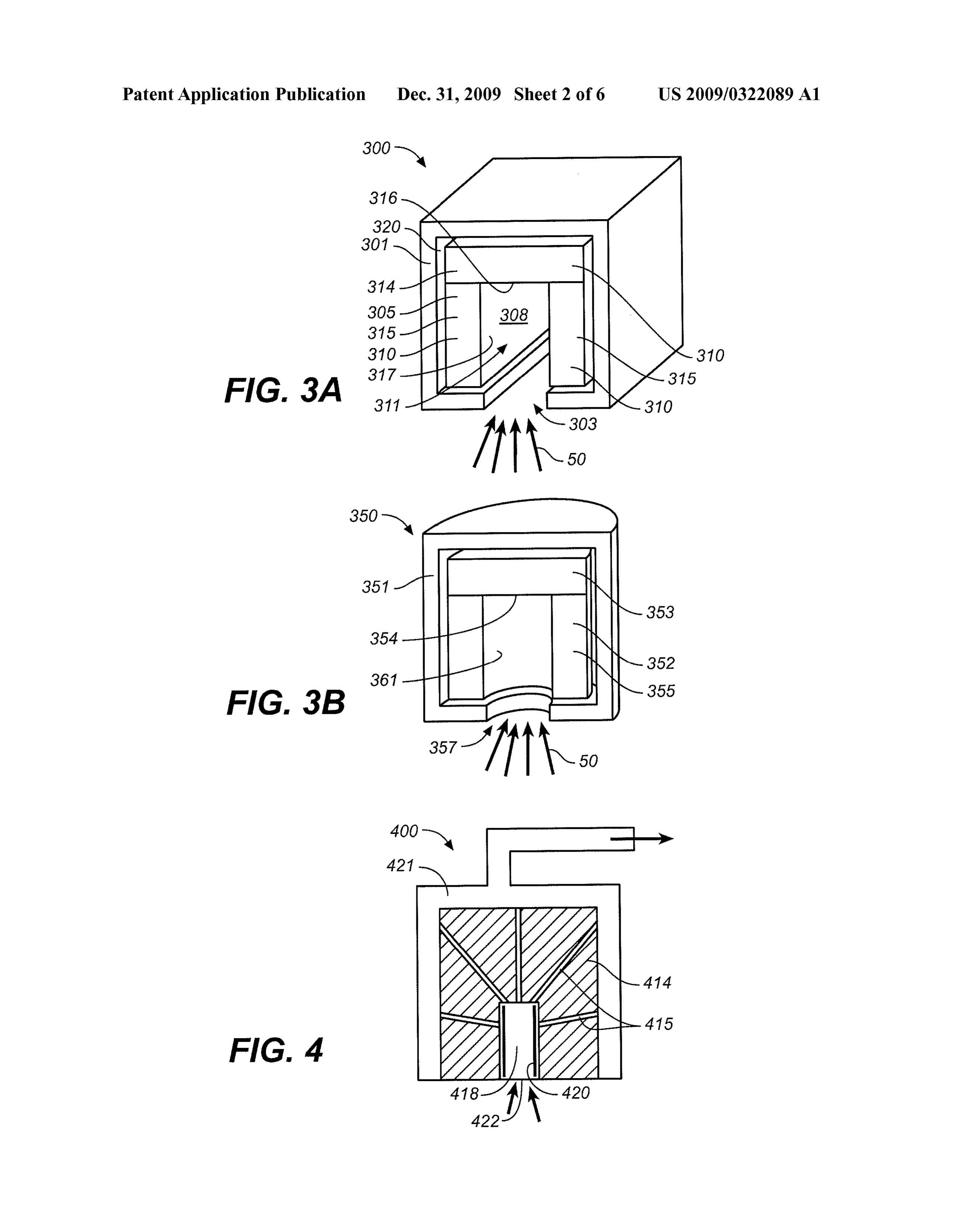
flowing the working fluid through one or more passageways working fluid to drive an electrical generator. In these plants, comprising interconnected interstitial spaces in the aggre the first heating stage comprises at least one of the Solar gate. energy receivers described herein. Thus, Some plants may 0030. Further, the methods may comprise adjusting a dis comprise a receiver that comprises an aperture through which placement between the aperture and an incident Surface of the concentrated Solar radiation is directed and a core comprising core so as to adjust an energy density or intensity on the core a refractory material, wherein the core absorbs incident solar and/or an efficiency of the receiver. radiation to generate thermal energy that is stored therein. 0031 Additional variations of methods for effecting That stored thermal energy in the core may then be used to energy exchange are provided. These methods comprise heat the compressed first working fluid. The first working directing concentrated Solar radiation into an apertured cavity fluid may be any suitable working fluid, but in many instances within a body of a receiver from reflectors within one or more may comprise primarily air.
fields of reflectors. The body has at least a major part of its 0036. The receivers used in these plants may be configured volume composed of a refractory material in which thermal energy is generated by bulk absorption of radiative energy. as tower-mounted receivers, or may be mounted at or near The body also has at least one passageway located therein. ground level. In instances where a receiver is tower mounted, The methods further comprise transferring the thermal the plants may comprise an array of reflectors, e.g., heliostats, energy to a working fluid by passing the working fluid though directing solar radiation to the tower mounted receiver to heat one or more passageways within the body. the compressed working fluid. In instances where a receiver is 0032 Variations of solar energy collector systems are mounted at or near ground level, the plants may comprise an described here. In general, the Solar energy collector Systems array of heliostats directing Solar radiation to an elevated comprise an array of reflectors configured to direct incident reflector that, in turn, redirects the solar radiation down to the solar radiation to one or more of the receivers described receiver.
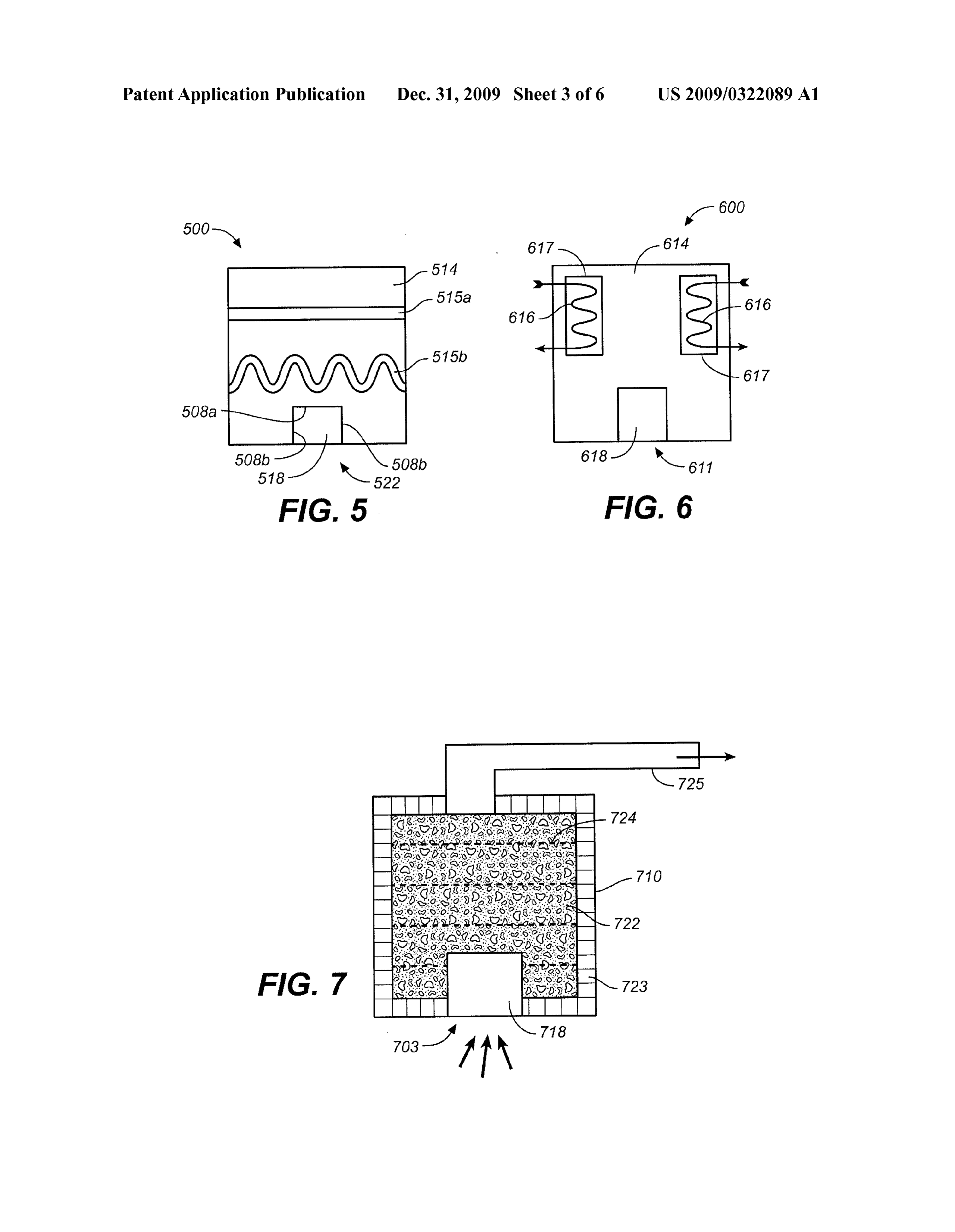
herein, and a pipe manifold configured to contain a first 0037. A receiver may be mounted so an outer surface and working fluid. In operation, the pipe manifold conveys the e.g. Substantially planar core Surface are each horizontal, or a first working fluid that has extracted stored thermal energy receiver may be positioned so that an outer Surface is inclined from the one or more receivers so that the heated first working and faces toward a solar field below it in a manner that solar fluid can be used in generating electrical energy. The first radiation is directed totally or partly from one side of the working fluid may be any suitable working fluid, but in some tower through the aperture and is incident on the core. cases the first working fluid may comprise primarily air. In these systems, the reflectors may be any suitable reflectors, 0038 A receiver may be configured such that a beam from but in some instances, the reflectors may have one or more a field of reflectors converges to its smallest size in the vicin two-axis heliostats having fixed horizontal axes and/or one or ity of the aperture, and the core of the receiver is positioned a more two-axis heliostats having fixed vertical axes. The sufficient distance from the aperture to reduce incident light reflectors may be configured as tower-mounted receivers in intensity so that the peak temperature on the core material is Some arrays, or the receivers may be mounted at or near within normal operating range for the material and the core ground level, e.g., in arrays utilizing beam down configura material remains substantially physically and chemically tions. stable. The beam may form an image on the core and e.g. on 0033 Certain solar energy collector systems may include a Substantially planar Surface of the core, similar to an image more than one receiver. In these systems, the receivers may be formed by a camera such as a pinhole camera. Image intensity the same as or different from each other. Where more than one may be substantially uniform as long as the Surface of the core receiver is present in a solar energy collector system, at least is not angled and/or curved with respect to the field of reflec one of the reflectors, e.g., a heliostat, may be configured to tors so that an approximate image of the reflector field is pivot so as to direct incident Solar radiation to any of the formed on the core, and the image is not skewed or distorted multiple receivers, e.g., depending on a position of the Sun to an extent that peak intensity in a portion of the image and/or seasonal conditions. creates a "hot spot” that exceeds to a significant extent the 0034 Certain solar energy collector systems may com highest temperature in the temperature range of normal prise a heat exchanger, where the heat exchanger is config operation for the material.
ured to transfer thermal energy contained in the first working 0039. Certain of these electrical energy plants may com fluid to a second working fluid. Any suitable working fluids prise one or more second or “bottom thermodynamic cycle may be used as the first working fluid and as the second working fluid in these systems. The first working fluid may heat engines, in which the second cycle heat engine utilizes for example comprise primarily air, and the second working waste thermal energy recovered from the first working fluid fluid may comprise steam, water, and/or a steam/water mix following its expansion to heat a second working fluid pow ture ering the second cycle heat engine. The second working fluid 0035 Variations of electrical energy generating plants are may be any Suitable working fluid, but in many cases, may provided here. In general, the plants may comprise one or comprise steam, water, and/or a water/steam mixture. The more first or “top” thermodynamic cycle heat engines (e.g. a second cycle may be a Rankine cycle. Any type of Rankine Brayton cycle heat engine) in which a receiver as described cycle heat engine may be used, e.g., a Rankine cycle in which herein is used to heat a compressed working fluid so that the the second working fluid is compressed, heated by the recov heated compressed fluid can be expanded to generate electri ered waste energy following expansion of the first working cal energy. That is, the plants may have a first compressor fluid, and then expanded through one or more turbines to configured to compress a first working fluid, a first heating drive an electrical generator.
stage configured to heat the compressed working fluid, and a 0040. The following description provides exemplary first turbine configured to expand the compressed heated embodiments of receiver-storage units for use in Solar energy
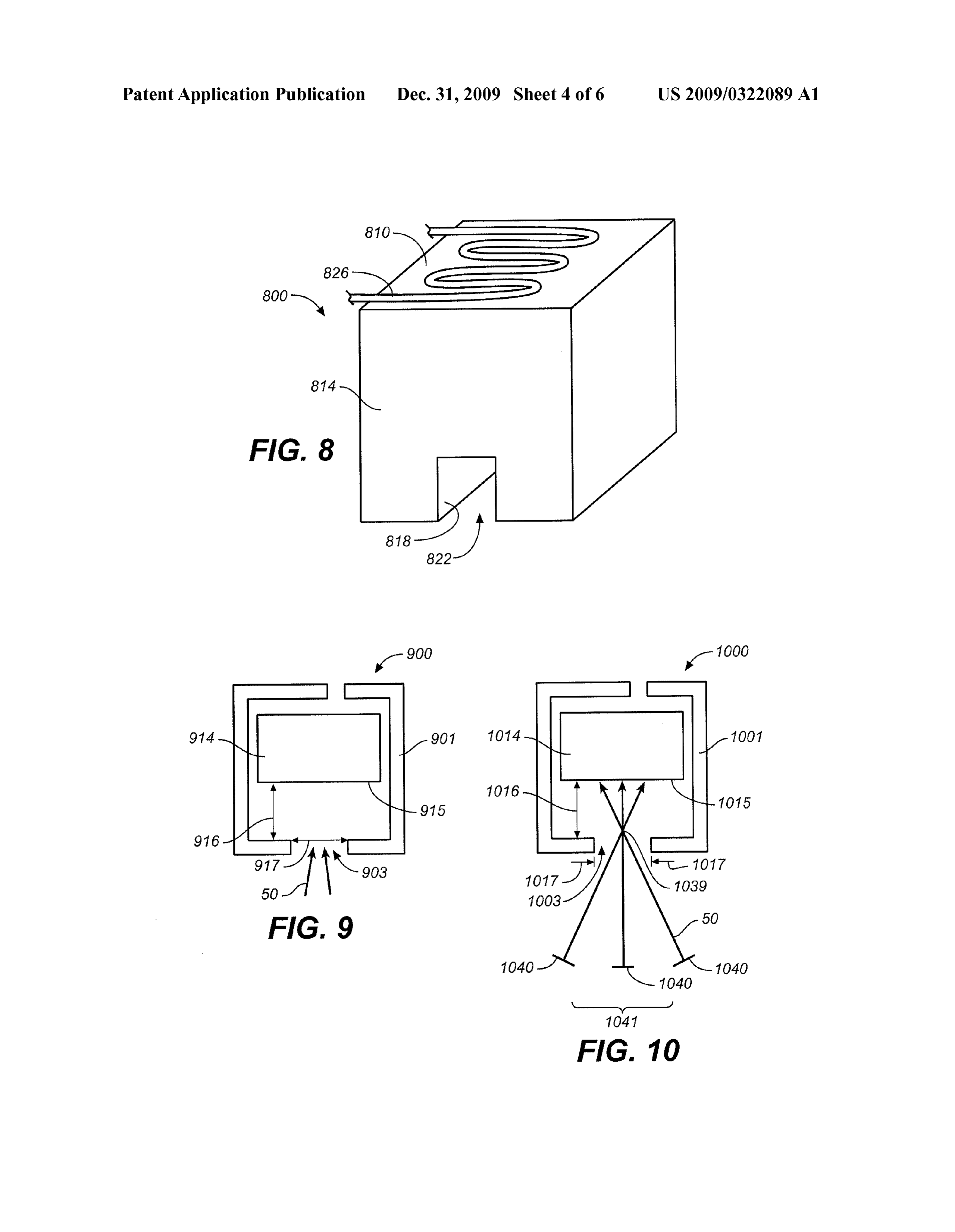
Page 12
US 2009/0322089 A1 Dec. 31, 2009
collector systems and electrical powerplants. The description collector systems and Solar-driven electrical power plants is provided in reference to the accompanying drawings. incorporating the receivers are described. 0056. It should be noted that any of the receivers may be
BRIEF DESCRIPTION OF THE DRAWINGS used in combination with any of the methods, Solar energy 0041. The invention will be more fully understood from collection systems, or electrical power plants, and one or the following description of an exemplary embodiment of a more aspects or features of the Solar energy collection sys receiver-storage unit for use in a Solar energy collector sys tems may be combined with one or more aspects or features of tem, the description being provided with reference to the the electrical power plants.
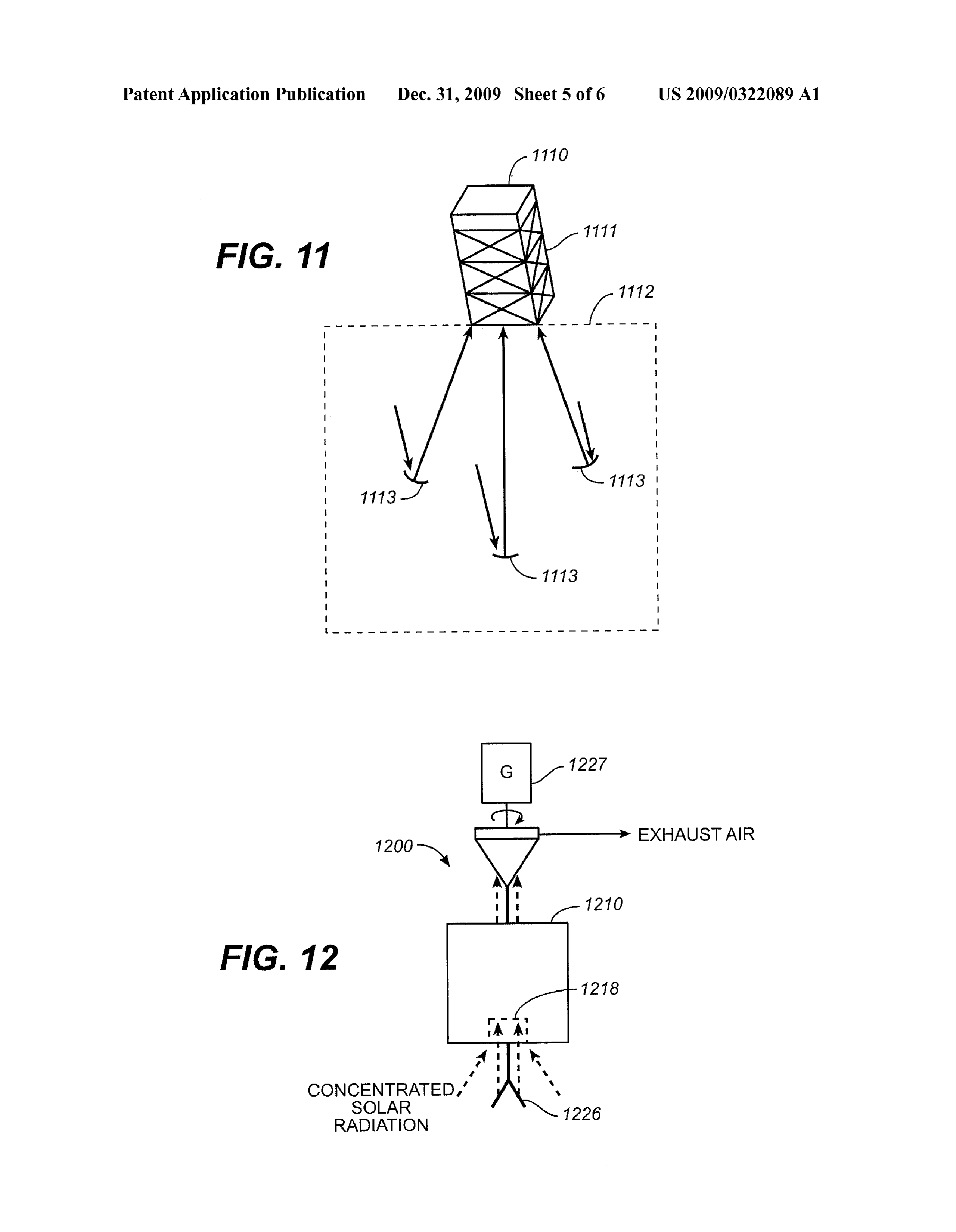
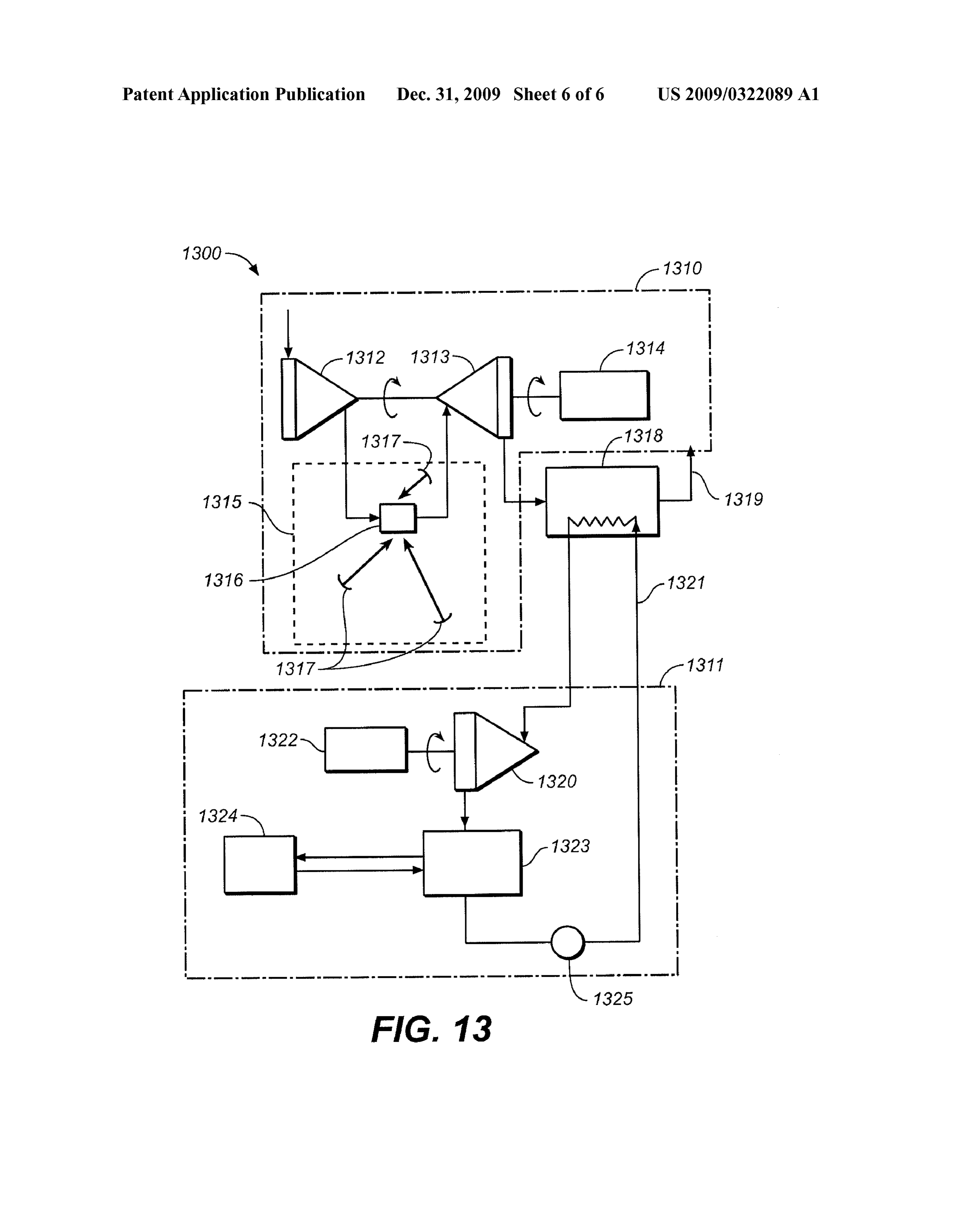
accompanying diagrammatic drawings. 0057. Several variations of receivers comprising a solar 0042 FIG. 1 shows an example of a receiver comprising a radiation absorbing body or core are disclosed here. As stated refractory core. above, the core comprises a refractory material. The core may 0.043 FIG. 2 shows a sectional elevation view of another in some examples be composed primarily of one or more embodiment of a receiver-storage unit located within a Sur refractory materials. The receivers comprise an aperture, rounding chamber. located for example in a receiver housing or in the core itself. 0044 FIGS. 3A and 3B shows sectional perspective views to control a region of irradiation, a surface of irradiation, of examples of receivers each comprising downward open and/or an energy density or intensity of irradiation on the ing, horizontally oriented apertures. core. Variations of receivers may be tower mounted (or oth 004.5 FIG. 4 shows a sectional elevation view of another erwise elevated on a hill, building, wall, etc.), e.g., for use in embodiment of a receiver. a tower Solar array (e.g., a multi-tower Solar array), so that 0046 FIG. 5 shows a sectional elevation view of yet Solar radiation is directed generally upward through the aper another embodiment of a receiver. ture to be incident on the Solar radiation absorbing core. In 0047 FIG. 6 provides a sectional elevation view of still certain variations, the receivers may be mounted at or near another embodiment of a receiver. ground level, e.g., for use in a Solar array configured for beam 0.048 FIG. 7 shows a sectional elevation view of a varia down operation, so that Solar radiation is directed generally tion of a receiver in which the core comprises a particulate downward through the aperture to be incident on the core. In material. certain variations, the receivers may be inclined between 0049 FIG. 8 illustrates an example of a receiver-storage horizontal and vertical facing toward the solar field below so unit including a heat exchanger in thermal contact with the that solar radiation is directed totally or partly from one side solar radiation absorbing core of the receiver. of the tower through the aperture is incident on the core. 0050 FIG. 9 illustrates a variation of a receiver in which a 0058. In a solar energy collector system, solar radiation is displacement between a Solar radiation absorbing core and an directed through the receiver aperture to be incident on a solar aperture in the receiver body can be varied. radiation absorbing receiver core by reflectors (e.g., 0051 FIG. 10 depicts a receiver having an aperture and a heliostats) within one or more reflector fields. Thermal COC.
energy may be generated in the body of the receiver by bulk 0052 FIG. 11 illustrates an example of a tower-mounted absorption and/or absorption of the radiative energy at the receiver-storage unit positioned adjacent a field of heliostats. core's Surface, or by absorption in cavity or channel structures 0053 FIG. 12 is a schematic representation of an electrical on the Surface of the core medium. The thermal energy may in energy generating system configured to operate in a quasi Some variations be transferred to a working fluid, e.g., to a working fluid passing through one or more fluid passage(s) isothermal Brayton cycle and incorporating a receiver-stor within and/or around the body or core. Thermal energy may age unit of a type described herein. be transferred to the working fluid either simultaneously with 0054 FIG. 13 is a schematic representation of combined the generation and storage of the energy in the body or core, cycle electrical generating system incorporating a receiver or optionally following a transitional period of storage of the storage unit of a type described herein. thermal energy in the body or core. Thus, the receivers may be
DETAILED DESCRIPTION
employed to accommodate transitory loss or reduction of
Solar energy impingement in a receiver body, e.g., due to 0055. The present application discloses receivers for use periods of low insolation.
in a Solar energy collector system. In general, the receivers 0059. Depending upon the refractory material employed, comprise a Solar radiation absorbing core or body that con a receiver body or core may in Some cases be formed as a verts the absorbed radiation to thermal energy. The solar substantially solid unitary body, with or without binding radiation absorbing core comprises a refractory material materials, e.g., by a moulding or other similar such process. capable of operating continuously at high temperatures For example, a refractory material may be cast and then fired resulting from the absorption of concentrated Solar radiation. to form a desired size and shape to be assembled in a block The core may then store the thermal energy so generated like matrix. Alternatively or in addition, some receiver bodies briefly, e.g., for a transient period Such as less than about 15 or cores may be constructed from bonded blocks comprising minutes, or for a more extended period, e.g., about 15 minutes one or more refractory materials, for example from bonded or longer, about 1 hour or longer, or for several hours. A blocks comprising aluminum oxide. A body may be cut, or working fluid, e.g., a fluid comprising primarily air such as otherwise machined or processed to form a desired size, ambient air, may be employed to extract stored thermal shape and/or configuration.
energy from the receivers. Thus, a receiver may in some 0060. As a furtherform of construction, some variations of instances function as an integrated receiver-thermal energy receivers may comprise a core comprising (e.g., composed storage unit. Also provided herein are methods and systems primarily of) a particulate refractory material. Such particu related to the receivers, e.g., methods for effecting heat late refractory material may comprise any refractory material exchange utilizing the receivers. Further, various Solar energy described herein or otherwise known, and in Some instances
Page 13
US 2009/0322089 A1 Dec. 31, 2009
may comprise more than one refractory material. For desired to omit a window, e.g., to eliminate reflective losses example, a refractory material may comprise an unbonded from the window which may be on the order of about 5% to heat-conductive (mineral) earthen material Such as quartzite. about 10%. In those situations, a receiver may be configured In Such variations, a core comprising one or more particulate to reduce convective thermal losses by positioning a down refractory materials may be located within a shell or housing. ward opening aperture in a Substantially horizontal orienta For example a receiver may comprise a container containing tion.
one or more particulate refractory materials, or a bale of a 0065. As stated above, some variations of receivers com loose refractory material in the form of chunks or pieces, prise one or more fluid passageways extending in and/or rocks, stones, gravel (each of which may or may not be around a receiver body or core. Such passageway or, more crushed), or even finer particles, or any combination thereof. usually, passageways in and/or around a receiver body and/or The shell or housing itself may comprise a refractory mate rial. For example, Such a shell or housing may comprise or be receiver core (if distinct from the receiver body) may be formed from bonded blocks comprising a refractory material, arranged so as to extend generally linearly through the body e.g., bonded blocks comprising aluminum oxide. A refractory or core, as the case may be. Optionally, e.g., when it is desired material incorporated into a shell or housing of a receiver to increase a residence time of a working fluid (heat exchange body may be the same or different as a refractory material fluid) in the body or core, one or more fluid passageways may incorporated into a receiver core. In certain variations, one or follow a curvilinear, serpentine, or circuitous path in and/or more metal structures Such as fins, a mesh, or grid-like struc around a receiver body or core. If a receiver body or core tures may be positioned within a receiver core and/or body, comprises one or more particulate refractory materials, par e.g., to promote spreading of absorbed thermal energy ticle sizes and/or a packing density may be optionally throughout the fluid within a receiver, and/or to promote selected to provide natural passageways through the body or channeling of thermal energy into one or more particular core; that is, passageways at least partially defined by inter regions of a core or body. Also, in Some variations, e.g., in this connected interstices between the particles. A working fluid latter form of construction, the core may be contained within or heat exchange fluid (e.g., a gas such as ambient air) may be a casing, e.g., a metal casing. A spacing, which may or may forced (e.g., pumped or drawn) through the one or more not be at least partially filled with a thermally insulating passageways to extract stored thermal energy from the material, may be provided between a core and a casing. receiver core or body. The heat exchange fluid may access the 0061 An incident surface of a receiver core or receiver one or more passageways in a variety of manners. For body configured to receive and absorb solar radiation may example, a heat exchange fluid (which may comprise prima have any desired configuration, e.g., an incident Surface may rily air) may be forced into a cavity, which may be open to one be substantially planar or contoured. If generally planar, an or more fluid passageways. In other variations, a heat incident Surface may be for example Substantially parallel to exchange fluid may enter one or more passageways without a plane defined by an aperture admitting Solar radiation into entering a cavity, e.g., via a side access or top access. the receiver, or substantially orthogonal to a plane defined by 0066. In one particular embodiment, a plurality of pas the aperture. In certain variations, a receiver body or core may sageways may be provided within a receiver body, with each comprise a cavity into which concentrated Solar radiation is passageway (which may optionally comprise an interstitial directed to be incident on one or more cavity walls. passageway as above mentioned) radiating outwardly to an 0062 An incident surface of a receiver body or core may in exterior or peripheral region of the body from an interior Some embodiments be substantially unclad Such that the inci region, e.g., a cavity. With this arrangement, ambient air may dent surface will, in use of the receiver, be exposed to con be employed as the heat exchange fluid and be drawn or centrated Solar radiation that is beamed through the aperture forced through the cavity, through the radiating passageways of the receiver. In certain variations, an incident Surface may and into a collecting chamber or the like. The resulting heated be optionally clad, e.g., with a protective lining comprising a air may then be used as a working fluid or be used to transfer thermally conductive material that may for example inhibit thermal energy to a (further) working fluid Such as water, ablation and/or sublimation of the underlying refractory steam, or a mixture of water and steam. material. Thus, for those receiver bodies or cores comprising 0067. When a gaseous working fluid (e.g., a working fluid a cavity into which Solar radiation is directed, one or more that comprises primarily air (e.g., ambient air)) is used to cavity walls may be clad as described. A cladding, if present, extract stored thermal energy from a solar radiation absorbing may in certain variations be removably secured to an incident core or body, as above described, the receiver may optionally Surface (e.g., a cavity wall in a cavity). For example, Such be interposed between a compressor turbine and a turbo removable claddings may be employed where it is desired to generator, with the compressor being employed to force com replace the cladding, e.g., for periodic replacement and/or for pressed gas (e.g., air) into the receiver and the turbo-generator repair. being driven by high temperature-high pressure air following 0063. If present, a cavity in a receiver body or receiver core its passage through the body or core of the receiver. Thus, the may be configured in various ways, for example as a cylin integrated receiver-storage unit may optionally be integrated drical cavity, as a generally cubic-shaped cavity, or any other with a turbo-compressor and a gas turbine to operate in a type of polyhedral shaped cavity. A cavity may in certain Brayton cycle. Non-limiting examples of Brayton cycle heat instances be configured so as to induce reflection, e.g., total engines and combined cycle power plants incorporating inte internal reflection of incoming radiation. grated receiver-storage units as described here are provided in 0064. During those periods when it is not necessary that U.S. patent application Ser. No. entitled “Combined the aperture be open, for example to permit air flow into the Cycle Power Plant” (Attorney Docket No. 62715-2000700) receiver (e.g., into a cavity in a receiver body), the aperture and filed concurrently herewith, and in U.S. Provisional may optionally be closed with or at least partially covered by Patent Application Ser. No. 60/933,619, entitled “Combined a window, e.g., a quartz, window. In some cases it may be Cycle Power Plant” (Attorney Docket No. 62715-3000700),
Page 14
US 2009/0322089 A1 Dec. 31, 2009
filed Jun. 6, 2007, each of which has already been incorpo Solar radiation to the ground or near ground mounted receiver. rated by reference herein in its entirety. In Such arrangements, a receiver aperture may be optionally 0068. In some embodiments, a passageway, or if more located in an upper region of the receiver (e.g., an upper than one, passageways may optionally comprise a liner, e.g., region of the receiver body or core). a thermally conductive liner Such as a carbon, graphite, or 0071. Within a receiver, a solar radiation absorbing core or metal liner. A liner, if present, may be positioned within a body, and an aperture that determines an irradiation region or hollow passageway or chamber within a receiver body or Surface on the body or core may be configured in various receiver core. In some circumstances, one or more spacer ways. FIGS. 1-7 illustrate some examples of possible receiver elements may be employed, e.g., to maintain separation of the configurations.
liner from the core or body. By maintaining Such separation (0072 Referring first to FIG. 1, a variation of a receiver 100 between a liner and a passageway it may be possible to reduce is illustrated that comprises a housing 101 that, in turn, com or avoid problems such as passageway blockage flowing from prises an aperture 103. Within the housing 101 is a solar differential coefficients of expansion between the liner and radiation absorbing body 105 that comprises a refractory the receiver body or core. material. The refractory material in the body may for example 0069. Receivers may have any suitable dimensions, and a be provided in the form of a monolithic mass, an aggregated Solar radiation absorbing body or core in a receiver may have material, a particulate material, a powder, a baled material, or any Suitable dimensions. For example, one or more receiver any combination thereof. Thus Solar radiation, e.g., concen and/or receiver body or core dimensions may be determined trated Solar radiation directed from an array of reflectors (e.g., by an amount of Solar radiation directed at the receiver, a heliostats) can pass through the aperture 103 to be incident on thermal energy storage capacity desired, the composition of a surface 107 of the core 105. In this particular variation, the the receiver body or core, the thermal stability of the receiver incident surface 107 may be substantially parallel to a plane core or window material at the temperature of operation, a defined by the aperture 103, e.g., substantially horizontal if height at which a receiver is to be used, or any combination the aperture is horizontal. A space 110 between the core and thereof. Thus, a receiver-storage unit may comprise a total the housing may be at least partially filled with a thermally volume in a range from about 1 m to about 200m. (A500 ft. insulating material (not shown). As described in further detail tower may have 1,000,000 square fi or 100,000 m of acces herein, the core 105 may or may not comprise one or more sible field, covered to about 50% with reflector. At 500 times passageways 109 directed through and/or around the core 105 optical concentration, the receiver aperture can be 100 m. If to convey a working fluid (e.g., air) to extract thermal energy the aperture is 1 m in depth and horizontal, the top surface stored in the core via heat transfer. would be 100m and the minimum volume would be 100 m. 0073. In some instances a receiver and its solar radiation An aperture through which Solar radiation passes to be inci absorbing body may comprise a unitary structure. FIG. 2 dent on the Solar radiation absorbing core or body may there illustrates an example of such a receiver. There, the receiver fore comprise an opening having an area of the order of about 200 comprises a generally solid unitary receiver body 201 0.8 m to about 100 m. In some variations, an aperture may that comprises a refractory material. Thus, incident Solar be adjustable, e.g., to tune the size of the opening. In certain radiation can be directed through aperture 203 to be received variations, an aperture may be configured with an entry guide into cavity 211 of the receiver core 201. The incident solar Such as a flared entry guide, and/or with a focusing element or radiation may be incident on any or all surfaces 208a and concentrator Such as a compound parabolic concentrator. 208b of the cavity 211 to be absorbed and converted into 0070. As stated above, receivers may be elevated (e.g. thermal energy that can be stored in the body/core 201 for a tower mounted receivers) or ground mounted receivers. If desired length of time, e.g., a transient period less than about tower mounted, a receiver may be mounted atop a Supporting 15 minutes, or a more extended period (about an hour, several tower having a height, typically on the order of about 15 m to hours, or longer). In this particular variation, cavity 211 pro about any of (50 m, 100 m, and 150 m), which may depend vides a top incident surface 208a that may be substantially upon the size (ground area) occupied by one or more associ parallel to a plane defined by aperture 203, as well as side ated reflector fields, e.g., one or more heliostat fields. The incident surfaces 208b that may be substantially orthogonal receiver aperture, which may be located in a receiver housing to a plane defined by aperture 203. In some variations, or within a receiver body itself (e.g., as an aperture that leads receiver 200 may be used in a configuration where aperture to a cavity in a receiver body), may be positioned to best 203 is substantially horizontal and opens downward, e.g., for receive focused radiation from the reflectors (e.g., heliostats). a tower mounted receiver. Although not shown, the body/core Thus, the aperture may optionally be positioned on the under 201 may comprise one or more fluid passageways configured side of a tower mounted receiver (e.g., on the underside of a to convey a working fluid to extract thermal energy stored in receiver body). For example, as described above, if the aper the core.
ture is substantially horizontal in a tower mounted receiver, 0074. Additional variations of receivers are shown in thermal losses due to convection at the aperture may be FIGS. 3A-3B. Referring first to FIG. 3A, receiver 300 com reduced. If a receiver is located adjacent one end of a reflector prises a housing 301 and a Solar radiation absorbing body field, a receiver aperture (e.g., an aperture in a receiver hous 305. Solar radiation can be directed through an aperture 303 ing or an aperture in a receiver body or core that leads to a to be incident on the body 305. In this particular variation, the cavity) may for example be positioned adjacent a lower mar body 305 is formed around a peripheral region of the housing ginal edge of the receiver body. In an alternate arrangement, 301 so as to form an interior cavity 311. In this particular the receiver may be illuminated as a secondary receiver, for variation, the body 305 comprises multiple sections 310 that example in a beam down system where a receiver may be may be arranged in any manner in the housing 301, e.g., to mounted at or near ground level. There, one or more fields of form a cavity 311 having incident surfaces 308 for receiving reflectors (e.g., heliostats) may reflect concentrated Solar and absorbing solar radiation 50 that is transmitted through radiation to an elevated reflector that, in turn, redirects the the aperture 303. Although the sections 310 are illustrated as
Page 15
US 2009/0322089 A1 Dec. 31, 2009
forming a block shaped cavity 311 having a cap 314 and 415, and into a chamber 421 that generally surrounds the sidewalls 315, other variations are possible, e.g., sections receiver body 414, all while the body 414 is being irradiated arranged to form a polygonal cavity. The body 305 may with concentrated solar radiation through aperture 422. The comprise an incident surface 316 on cap 314 that is substan resulting heated working fluid, e.g., heated air, may be used tially parallel to a plane defined by the aperture 303, and an downstream as a working fluid, or be used to transfer thermal incident surface 317 on sidewalls 315 that is substantially energy to a (further) working fluid, for example to produce orthogonal to the aperture plane. Any space between the Superheated Steam.
housing 301 (e.g., space 320) may optionally be at least 0078. In certain variations, one or more fluid channels or partially filled with a thermally insulating material. As shown passageways may be directed in a generally transverse man in FIG.3B, a variation of a receiver 350 is shown in which the ner across a receiver body or core. For example, referring to receiver housing 351 contains a receiver body 355 comprising FIG.5, receiver 500 comprises abody 515 that comprises two a cylindrical section 352 (that may in turn comprise multiple types of fluid channels, 515a and 515b. Incident solar radia subsections) and a cap section353 to form a cavity 361 having tion may be transmitted through the aperture518 and received a circular cross-sectional shape. Thus, an incident Surface 354 on any or all of the incident surfaces of cavity 518 (e.g., on the cap 353 may be substantially parallel to a plane defined sidewall surfaces 508b and/or top surface 508a). In this par by an aperture 357 in the receiver housing 351. For either of ticular example, both fluid channels 515a and 515b extend the variations shown in FIGS. 3A and 3B, the body may transversely across the body 514 to convey a working fluid comprise one or more fluid passageways (not shown) to con (not shown) to extract thermal energy. In this example, fluid Veya working fluid to extract stored thermal energy from the channel 515a follows a generally straight path, whereas fluid body. channel 515b follows a serpentine path, e.g., to increase a 0075 Fluid passageways or fluid channels, if present in a path length of the working fluid through the body 515 so as to body, may have a variety of configurations, and in general any extract more thermal energy. Although the fluid channel 515b fluid passageway configuration may be used in combination is illustrated as generally serpentine, any variation of a cur with any receiver and/or body configuration. Examples of vilinear or circuitous channel through the body may be various fluid passageways that may be used to extract stored employed to increase a path length. thermal energy from the refractory bodies described herein 0079. Some receivers may comprise fluid channels that are are provided in FIGS. 4-7. It should be noted that a single located in discrete regions of a receiver body. Such an receiver may utilize more than one type of fluid channel; thus, example is illustrated in FIG. 6. There, receiver 600 com variations are contemplated which include any combination prises a solar radiation absorbing body or core 614, a cavity of the fluid channel types. In any of the variations, the way in 618 and an aperture 611. Located within body 614 are one or which the channels are positioned within the body of the more pocket-like chambers 617. In these variations, the fluid receiver may be dependent upon the method employed from channels 616 may be located as a separate channel unit within one unit to another to construct the receiver body. one or more of the pocket-like chambers 617. The pocket like 0076. In some variations, the fluid passageways may be chambers 617 may contain a fluid (e.g., a heat transfer fluid directed radially outward from an interior, e.g., central, region such as air), and the fluid channels 616 may for example of the body to a periphery of the body. Referring now to FIG. comprise a conduit or pipe so as to allow a working fluid 4, receiver 400 comprises a housing 421 containing a Solar contained within the conduit to be heated by a fluid contained radiation absorbing body or core 414. The receiver body or in the chambers 617. In other variations, the pocket-like core 414 may comprise, or be formed or constructed from a chambers may comprise a Solid refractory material, e.g., a refractory material (as defined above). In some variations, the monolithic material, an aggregated material, rocks, gravel, body or core 414 may be, but need not be, constructed from sand, or any combination thereof, that may have a different blocks that comprise (e.g., are composed primarily of) alu composition and/or different density than the bulk of the core minum oxide in a fired, heat resistant clay binder or matrix. 614. For example, the composition of the core material within Solar radiation can be transmitted through an aperture 422 to the chambers 617 may be selected to have an increased ther enter an internal cavity 418 of the body 414. Optionally, a mal conductivity So as to facilitate improved heat transfer to cladding layer 420 may at least partially line the cavity 411, a working fluid in the fluid channels 616. e.g., as a protective layer for a refractory material contained 0080. As an alternate construction, a receiver may com within the body 414. The receiver variation shown in FIG. 4 prise a core that, in turn, comprises one or more particulate may have any dimensions, and may beformed approximately refractory materials, as described above. The core may be as a cube with approximately 2.5 m side dimensions, composed of, or primarily composed of one or more particu although, depending upon the output power requirements of a late refractory materials. An example of Such a receiver is system of which the receiver is a part, the receiver may be provided in FIG. 7. In this particular example, the core 722 of constructed with a Volume within a range of for example, receiver 710 may comprise (e.g., be formed or constructed about 1.0 m to about 20.0 m. from), for example, one or more unbonded thermally conduc 0077. Fluid channels or passageways 415 are provided tive (mineral) earthen refractory materials such as rocks, within the body 414 of the receiver for conveying a working stones, gravel, sand, and combinations thereof. The thermally fluid (typically a heat exchange fluid) through the body to conductive refractory material may in some cases comprise extract stored thermal energy. In this particular example, the quartzite. In this embodiment, the refractory core 722 is channels 415 are formed within the body itself, and are located within a shell or housing 723 that may comprise a directed radially outward from an interior region of the body refractory material that may be the same or different as that (e.g., cavity 418) to an outer peripheral region of the body. used in the core. In certain examples, the housing 723 may be Thus, in use of this embodiment, a gas such as ambient air formed from bonded blocks of a refractory material, e.g., may be employed as a working fluid and be forced or drawn aluminum oxide. Also metal structures such as fins or a grid or through the cavity 418, radially outward through the channels mesh 724 may be disposed within the core 722, e.g., to pro
Page 16
US 2009/0322089 A1 Dec. 31, 2009
mote spreading of thermal energy though the core, and/or to I0084 As stated above, an aperture in a receiver (e.g., in a promote channeling of the thermal energy into selected par housing or in a receiver body or core itself), may have a ticular regions of the core. Although not shown in FIG. 7, an cross-sectional area of the order of about 0.8 m to about 7.0 optional casing, e.g., a metal casing, may be used to contain m. In some variations, an aperture may be adjustable, e.g., to core 722. In those variations, a space that may or may not be tune the size of the opening. Although not so shown in the at least partially filled with a thermally insulating material, variations of receivers illustrated herein, any aperture may be may be provided between the core and the casing. Although fitted with a window that is substantially transparent to the this particular variation is illustrated as comprising a cavity Solar spectrum over a wavelength range of interest, e.g., a 718 for receiving incident solar radiation through the aperture quartz window. In certain variations (and also not shown), one 703, other variations are contemplated that comprise no cav or more optical elements, e.g., a radiant energy concentrator, ity, so that Solar radiation can be incident on a Surface of core may be placed in the aperture to condition the incident Solar radiation.
722, e.g., a relatively planar Surface.
0081 For receivers comprising a particulate core, such as I0085 For any of the receiver variations described herein, a heat exchange fluid may be thermally contacted with a Sur illustrated in FIG. 7, particles sizes, particle size distribution, face of the receiver body or core to extract thermal energy and a packing density may be such that one or more fluid from the Surface. This heat exchange scheme may be used passageways may be established though interconnected inter alternately to or in addition to a thermal extraction scheme Stitial spaces in the core. With this arrangement, a heat involving conveyance of a heat exchange fluid though a pas exchange fluid Such as ambient air may be drawn or forced sageway in a core. For example, a heat exchange fluid in through Such passageways the core (e.g., via cavity 718, if contact (e.g., physical and/or thermal contact) with a Surface present) and be conveyed form the receiver by a feed line 725, of the receiver body or core, or one or more pipes containing either directly or by way of a plenum or the like (not shown). the heat exchange fluid that is in thermal contact with a The resulting heated fluid (e.g., heated air) may then be used Surface of the core, may be used to extract thermal energy as a working fluid for example in an energy generating cycle. from the body or core.
Alternatively or in addition, the resulting heated fluid may be I0086 FIG. 8 provides an example of receiver in which used to transfer thermal energy contained therein to a (fur extraction of heat by a heat exchange fluid occurs at a surface ther) working fluid Such as water. of the receiver core. There, receiver 800 comprises a solar 0082 For any of the receiver variations, an incident sur radiation absorbing core 814 comprising a refractory mate face (e.g., a cavity surface such as 208a and 208b in FIG. 2) rial. Bulk absorption of solar energy that passes through the of the receiver body or core may be clad with a protective aperture 822 (and in this variation enters cavity 818) results in cladding or liner (e.g., cladding 420 as illustrated in FIG. 4). thermal energy generation and storage in the core 814. A heat Such a cladding, if present, may function for example to exchange fluid contained in a manifold 826 may be placed in inhibit ablation and/or sublimation of the refractory material thermal contact with an external surface 810 of the core 814 in the body or core, e.g., a refractory material that forms one to extract stored thermal energy from the core for use, e.g., in or more walls of a cavity into which solar radiation is directed. driving an energy generating cycle. Although not shown in Certain variations of claddings may b removably secured to FIG. 8, the core itselfmay comprise one or more internal fluid an incident Surface (e.g., in a cavity) So as to permit replace passageways (e.g., as shown above) for conveying a working ment, e.g., in the event of undesired surface erosion or dam fluid to extract thermal energy from the bulk of the core 814. age. Thus, receivers may comprise an external means for heat 0083. For any of the receiver variations, a refractory mate extraction via external thermal contact with an external Sur rial may have any Suitable composition and may be in any face of a refractory body or core, e.g., as illustrated in FIG. 8, form, e.g., monolithic, molded, aggregated, particulate, pow and/or one or more fluid channels configured for conveying a dered, or any combination thereof. In general, the refractory working fluid in and/or around a refractory body or core, as material in the receiver may comprise any refractory material described herein.
that is Substantially opaque to Solar radiation and remains I0087. In some variations of receivers, a displacement substantially stable when exposed to temperatures that are between the aperture through which solar radiation is directed established with absorption of concentrated solar radiation, and the Solar radiation absorbing body may be adjusted or e.g., continuous operation at a temperature of about 800° C. selected to determine an energy density or intensity of the or higher as described above, e.g., about 800° C. to about solar radiation that is incident on the body. For example, the 3000° C., or about 800° C. to about 2500° C. Some of the displacement between the aperture and the core may be refractory materials may be able to withstand continuous adjusted or selected to increase an energy collection effi operation attemperatures of at least about 1000°C., or at least ciency of the receiver. Such adjustment may be completed at about 1200° C., or even higher. In certain variations, a installation, may be carried out periodically or regularly, and receiver body or core may comprise a combination of refrac may be completed manually or automatically. For example, tory materials. A refractory material may comprise a refrac Such adjustment may be made to account for seasonal varia tory metal, a ceramic, and/or a cermet. Non-limiting tions, and/or aging of a receiver. Referring now to FIG. 9, a examples of refractory materials that may be used include variation of a receiver is illustrated in which a displacement alumina, silica, carbon, magnesia, Zirconia, silicon carbide, between a receiver aperture and an incident Surface of a titanium carbide, tantalum carbide, chromium carbide, nio receiver core can be varied. There, receiver 900 comprises a bium carbide, zirconium carbide, molybdenum disilicide, housing 901 that, in turn, comprises an aperture 903. Con calcium oxide, graphite, chromite, dolomite, magnesite, tained within the housing 901 is a solar radiation absorbing quartzite, aluminium silicate, tungsten, molybdenum, nio body or core 914. Solar radiation (e.g., concentrated solar bium, tantalum, rhenium, beryllium, and combinations radiation reflected by one or more reflectors such as thereof. heliostats) is transmitted through the aperture 903 to be inci
Page 17
US 2009/0322089 A1 Dec. 31, 2009
dent on an incident surface 915 of the receiver body or core utilizing a receiver that comprises a core composed primarily 914. Body 914 comprises a refractory material, as described from a refractory material or a combination of refractory above, and may or may not comprise one or more fluid pas materials. The methods further comprise transferring thermal sageways, as described above. In general the incoming Solar energy stored in the core following bulk absorption of inci radiation 50 has been focused by a reflector, so that an inci dent radiation by passing the working fluid through one or dent beam may be converging or diverging as it enters the more passageways in and/or around the core, as described aperture 903 and impinges upon surface 915, depending on above. The methods may comprise directing concentrated where a focal point, or region of highest concentration, occurs Solar radiation through the aperture to be incident on the core in the reflected radiation's path from a reflector to the receiver so that the core reaches a continuous operating temperature of 900. Thus, a displacement 916 between a plane defined by the about 800° C. or higher, e.g., about 1000° C. or higher, or aperture 903 and the incident surface 915 may be adjusted to about 1200°C. or higher. The working fluid may be passed determine an energy density or intensity incident on the Sur through the passageway or passageways by using any Suitable face 915. Further, a cross-sectional dimension 917 of the technique, e.g., the working fluid may be pumped or drawn aperture 903 may be adjusted, which may also affect the through a passageway. The working fluid used in the methods energy density or intensity incident on the surface 915. may be any suitable working fluid, but in many cases may 0088. In certain variations, focusing properties of a reflec comprise primarily air.
tor and a distance between the reflector and the receiver may 0090 The methods may comprise passing a working fluid be adjusted so that reflected solar radiation reaches a focal through any one of a variety of configurations of passageways point, or region of highest energy concentration approxi to extract stored thermal energy from the core. For example, mately at or prior to reaching a plane defined by the aperture. methods may comprise flowing the working fluid through a Such a situation is illustrated in FIG.10. There, receiver 1000 passageway directed radially outward from an interior region comprises a housing 1001 that, in turn, contains a refractory to a peripheral region, or through a serpentine, helical or other core 1014 having a surface 1015 for receiving incident solar circuitous passageway. Certain methods may comprise flow radiation to allow bulk absorption of at least a portion of that ing a working fluid through a refractory core comprising a radiation and subsequent bulkheating in the core 1014. Solar particulate aggregate.
radiation is incident on one or more reflectors 1040 in an array 0091. The methods may be used with tower mounted 1041. The reflectors (e.g., fixed horizontal axis and/or fixed receivers, or receivers mounted at or near ground level. In any Vertical axis heliostats) may be configured to track the Sun and case, the methods may comprise adjusting a cross-sectional reflect incident Solar radiation to the receiver 1000. In this dimension of a receiver aperture and/or a displacement particular variation, the reflectors 1040 are focusing reflec between the aperture and an incident Surface of a core, e.g., to tors. A distance between a reflector and a receiver, combined adjust an energy density or intensity incident on the core with focusing properties of that reflector, determine a focal and/or to increase a collection efficiency of the receiver. For point, or at least a region of highest energy concentration for example, the methods may comprise directing concentrated radiation that is not sharply focused, of the reflected solar Solar radiation through a receiver aperture so that a point or radiation 50. In some cases, a receiver may be positioned so region of maximum energy density or intensity occurs at or that a focal point or region of highest energy concentration before the aperture where materials which can overheat are (e.g., indicated as region 1039 in FIG. 10) occurs approxi not present, and so that the Solar radiation is at least somewhat mately at or prior to the aperture, so that Solar energy incident divergent as it impinges on the core. As described above, on a surface of a refractory core is divergent. Thus, intensity certain methods may comprise directing the concentrated variations on the incident Surface may be reduced, e.g., so that Solar radiation to be incident on a Substantially horizontal approximately uniform irradiation of the incident Surface of surface of the core, or to be incident on a substantially vertical the Solar radiation absorbing core may be achieved, which surface of the core, or a combination thereof. Certain ones of may allow overall higher incident Solar radiation energy den the methods may comprise at least partially imaging an array sities to be used, increase conversion efficiency of the of reflectors on a substantially horizontal incident surface of receiver, and/or reduce local hotspots and the like that can the core, where the array of reflectors is used to direct solar degrade performance, and in some cases, lead to catastrophic radiation through the aperture. Any type or configuration of failure. In some instances, a displacement between the aper reflectors may be employed to direct concentrated Solar radia ture 1003 and the incident surface 1015 of the core may be tion through the aperture to be incident on the core. For adjusted so as to approximately image at least a portion of the example, an array comprising fixed horizontal axis and/or reflector array 1041 on the surface 1015. By adjusting a fixed vertical axis heliostats may be used. displacement 1016 between the incident surface 1015, and 0092. Certain other methods for effecting energy optionally a cross-sectional dimension of the aperture 1003, exchange between Solar radiation and a working fluid are and optionally a position of the focal point of the reflected disclosed. These methods comprise directing concentrated solar radiation 50 relative to the aperture, an energy density or Solar radiation through a substantially horizontally oriented intensity incident on the surface 1015 of the core 1014 may be aperture in a lower portion of a body of a tower mounted controlled. receiver so that the solar radiation is incident on and absorbed 0089. The receivers as described herein may be used in by a core disposed within the body to generate thermal energy methods for effecting heat exchange to generate thermal in the core. The core comprises a refractory material. The energy from Solar energy are also described here. In general, methods further comprise transferring thermal energy from the methods comprise directing concentrated Solar radiation the core to a working fluid, e.g., a working fluid that com through a receiver aperture so that Solar radiation is incident prises air. Variations of the methods may comprise flowing on a receiver core. Any of the receivers described above, the working fluid through one or more passageways in and/or including any variation of receiver core and any variation of around the core to facilitate extraction of thermal energy from aperture, may be used. Thus, the methods may comprise the core. Any type or configuration of passageway may be
Page 18
US 2009/0322089 A1 Dec. 31, 2009
used in these methods. Further, these methods may comprise dated Jan. 29, 2007 and in International Patent Application adjusting a displacement between the aperture and an inci No. PCT/AU2008/000096, dated Jan. 29, 2008, each of dent Surface of the core so as to adjust an energy density or which is incorporated by reference herein in its entirety, may intensity incident on the core and/or an efficiency of the be employed for driving heliostats. receiver. 0097. The reflectors (e.g., heliostats) may in use be driven 0093. The receivers and methods as described herein may to track east-to-west progression of the Sun during each diur be used in a variety of configurations in Solar energy collector nal period and to reflect incident Solar radiation into an aper systems. An example of a tower mounted receiver for receiv ture (referred to in more detail above) of the receiver 1110. In ing energy from one or more reflector fields is provided in the case where a plurality of spaced-apart receivers 1110 is FIG. 11. There, a receiver-storage unit (hereinafter referred to located within a reflector field 1112 or the receivers are simply as a “receiver') 1110 is positioned at or near the top of located at, for example, opposite ends of a field, various ones a steel tower 1111 (e.g., a skeletal or space frame steel tower) of the reflectors may be orientated to reflect radiation to one that is located in proximity to (e.g., adjacent one end of) a field only of the receivers, or some of the reflectors may be driven 1112 of reflectors 1113, which may for example comprise selectively to pivot to such an extent as to shift the reflected heliostat reflectors. Four only reflectors are for convenience radiation from one receiver to another. Non-limiting shown in the figure but a single tower mounted receiver would examples of reflectors that may be reoriented to direct inci normally be associated with a very much larger number of dent solar radiation from one tower to another are described in reflectors. Also, in an alternative arrangement a plurality of U.S. Pat. No. 5,899,199 issued May 4, 1999 to David Mills, spaced-apart tower-mounted receivers might be positioned which is incorporated by reference herein in its entirety. In within or at the margins of a large field of reflectors. In either any event, the reflectors may function collectively to concen of these optional cases, the reflectors may be controlled and trate solar radiation at or near the aperture of the receiver or, driven for orientation toward a single receiver or to be re if more than one, multiple receivers, as is described above, orientated from one receiver to another in order to optimise e.g., in connection with FIGS. 9 and 10. Solar energy collection and to minimise the possibility of 0.098 Receivers as described herein may function to heat a reflector shading. Although the receiver 1110 is illustrated as working fluid in aheat engine employing e.g. a Brayton cycle. being positioned on an end of field 1112 in FIG. 11, the field Examples of energy generating cycles and combined cycle 1112 and the reflectors 1113 within the field may have any power plants using Solar radiation absorbing refractory suitable arrangement with respect to the receiver 1110. For receivers to heat a working fluid are provided in U.S. patent example, in some variations, reflectors 1113 may be arranged application Ser. No. entitled “Combined Cycle circumferentially with respect to receiver 1110, e.g., so that Power Plant.” (Attorney Docket No. 62715-2000700), filed the Solar radiation directed to the receiver takes on a generally concurrently herewith, and U.S. Provisional Patent Applica conical shape. In other variations, the reflectors 1113 may be tion Ser. No. 60/933,619, entitled “Combined Cycle Power arranged in arcs or rows. Such arcs or rows may be arranged Plant” (Attorney Docket No. 62715-3000700), filed Jun. 6, symmetrically with respect to the receiver 1110, or may be 2007.
arranged preferentially on one or more sides of the receiver 0099 FIG. 12 provides an example of a heating stage that 1110. can be used to heat a working fluid (e.g., air). There, heating 0094. In certain other alternative arrangements, a receiver stage 1200 comprises a receiver 1210 having any configura may be mounted at or near ground level, e.g., as a secondary tion as described herein that is interposed between a compres receiver in a beam down configuration as described above. sor-turbine 1226 and a turbo-generator 1227. The compressor There, an elevated reflector may be configured to receive 1226 is employed to force compressed air into the cavity 1218 reflectors solar radiation from one or more reflector fields, of the receiver 1210 and the turbo-generator 1227 is driven by similar to field 1112 illustrated in FIG. 11. The elevated high-energy-level air following its passage through the receiver may redirect the reflected radiation downward so as receiver. Even though the heating stage 1200 in this variation to be transmitted through an upward opening aperture of a is solar powered, the energy storage capabilities of the receiver as described herein. Larger refractive cores may be receiver 1210 used to heat the working fluid may dampen or accommodated in Such a ground mounted arrangement. reduce fluctuations inheat that may result from periods of low 0095. The height of the tower 1111 may be determined, at insolation. The storage capacity of the receiver 1210 may be least in partin any given case by the size (area) of the reflector selected so that the Supply of heated compressed air is suffi field (and hence by the distance between the farthest reflector ciently stable to drive turbo generator 1227, e.g., without the 1313 and the tower) and, to some extent, by the spatial rela need for auxiliary or Supplemental fuel to powerheating stage tionship of the reflectors. However, the tower may typically 1200. Although the heating stage 1200 is illustrated in con have a height in the range from about 15 m to about 50 m. nection with a Brayton cycle heat engine in FIG. 12, the 0096. Each reflector 1313 may comprise a two-axis receivers as described herein may be used in other heating heliostat having a fixed vertical axis but, in the interest of cycles that may be used in other types of energy generating achieving increase ground coverage with the reflectors, each cycles that employ a heated working fluid. reflector may desirably comprises one having a fixed hori 0100 FIG. 13 illustrates an example of a combined cycle Zontal axis, for example as disclosed in Australian Provi power plant utilizing a receiver as described herein. There, sional Patent Application No. 2007900391, dated Jan. 29, power plant 1300 comprises two interconnected power gen 2007 and International Patent Application No. PCT/ erating systems; a first of which (designated by numeral AU2008/ entitled “Solar Energy Collector 1310) is a heat engine employing a Brayton cycle and the Heliostats' filed Jan. 29, 2008, each of which is incorporated second of which (designated by numeral 1311) is a heat by reference herein in its entirety. In some variations, a col engine employing a Rankine cycle. The first system 1310 lision avoiding Solar tracking system of the type disclosed in comprises a turbo-compressor 1312, to which a first working Australian Provisional Patent application No. 2007900390, fluid in the form of ambient air is admitted, and a gas turbine
Page 19
US 2009/0322089 A1 Dec. 31, 2009
1313 which provides rotary drive to both the turbo-compres working fluid. The condenser coolant fluid cooling system sor 1312 and an electric generator 1314. Following its com may embody evaporative cooling, forced air cooling, Subter pression the first working fluid is heated in a heating system ranean heat exchange, or any combination thereof. 1315 and is delivered to the turbine 1313 where it expends a 0104. In an alternative (not illustrated) embodiment, air major part of its acquired energy by expanding through and cooled condensing may be employed for condensing the out driving the turbine 1313. put vapour from the turbine 1320. In such case, and if the plant 0101. In the power plant variation illustrated in FIG. 13, comprises a solar energy collector system such as that indi one or more receivers 1316 (as described herein, and which cated by reflector field 1315, a plurality of air cooled con may be tower mounted or ground mounted) receives and densers may be positioned within the reflector field 1315 and absorbs concentrated solar radiation reflected by one or more draw coolant air from a Zone shaded by the reflectors 1317. fields of reflectors 1317, which may be for example any Non-limiting examples of air cooled condensers that may be heliostats as described herein or otherwise known (e.g., fixed used in connection with the powerplants disclosed herein are vertical axis two-axis heliostats or fixed horizontal axis two provided in U.S. patent application Ser. No. entitled axis heliostats). Only three reflectors 1317 are for conve “Convective/Radiative Cooling Of Condenser Coolant’ (At nience shown in FIG. 13 but, depending upon a desired power torney Docket No. 62715-2000500), filed Jun. 6, 2008, and output capacity of the turbine 1313-generator 1314 set, one or U.S. Provisional Patent Application Ser. No. 60/933,574, more reflector fields may normally comprise many hundreds entitled “Convective/Radiative Cooling Of Condenser Cool of reflectors, e.g., heliostats. Although not so shown in FIG. ant’ (Attorney Docket No. 62715-3000500), filed Jun. 6, 13, if the receiver 1316 is a tower-mounted receiver, the 2007, each of which is incorporated by reference herein in its compressor 1312, turbine 1313 and first generator 1314 may entirety.
also be mounted on the tower as a quasi-integrated assembly 0105 Still referring to FIG. 13, the second working fluidin on the tower. Such an arrangement may avoid or reduce the its liquid phase may be delivered by a pump 1325 from the need to transport very high temperature gas from the receiver condenser 1323 to a heat exchanger (e.g., a heat exchanger 1316 to ground level where the first turbine 1313 and first within a thermal energy storage system 1318, if present, generator 1314 might alternatively be located. Having where thermal energy, e.g., residual thermal energy recovered expanded through the gas (first) turbine 13, in certain varia from the first cycle 1311 which may or may not have been tions at least a portion of the first working fluid may be stored in a storage unit 1318, and/or thermal energy Supplied directed to a mediating thermal energy storage system 1318 by any type of energy source, is transferred by heat exchange where residual thermal energy contained in the first working to the second working fluid in an amount to generate Super fluid is released (by heat exchange) to a thermal energy Stor heated steam for delivery to the steam turbine 1320. Thus, the age medium within the thermal energy storage system 1318. first cycle or system 1310 combines with the second cycle or Examples of mediating thermal energy storage units are system 1311 to provide at least a portion of the thermal energy described in U.S. patent application Ser. No. entitled required to power the second system. “Combined Cycle Power Plant” (Attorney Docket 62715 0106. This disclosure is illustrative and not limiting. Fur 2000700), filed concurrently herewith, and U.S. Provisional ther modifications will be apparent to one skilled in the art in Patent Application Ser. No. 60/933,619, filed Jun. 6, 2007, light of this disclosure and Such modifications are intended to each of which has already been incorporated by reference fall within the scope of the appended claims. Each publication herein in its entirety. Then, having expended all (or, at least, a and patent application cited in the specification is incorpo majority) of its acquired energy, the first working fluid may be rated herein by reference in its entirety as if each individual exhausted to the atmosphere as indicated by numeral 1319. publication or patent application were specifically and indi Of course, if no mediating thermal energy storage unit is vidually put forth herein.
employed, the first working fluid may be exhausted immedi 1. A receiver for use in a solar energy collector system, the ately after turbine 1313. receiver comprising:
0102 The second system or cycle 1311 within the power a core configured to absorb solar radiation directed through plant 1300 comprises a second turbine 1320 (e.g., a steam an aperture in the receiver, the core composed primarily turbine) through which a second working fluid is directed by of a refractory material; and way of a closed loop 1321. The second working fluid com one or more fluid passageways in the core for conveying a prises condensed water, Saturated vapour (wet steam) and working fluid through and facilitating extraction of ther Superheated Steam, depending upon its position within the mal energy from the core.
loop 1321. Superheated steam is admitted to and expands 2. The receiver of claim 1, wherein the aperture is situated through the turbine 1320 and the resultant expended energy is on a lower surface of the receiver and is substantially hori applied to drive a second electric generator 1322. Although Zontally oriented.
not shown, the electrical output from the first generator 1314 3. The receiver of claim 1, wherein an incident surface of and the second generator 1322 may each be delivered to an the core is substantially horizontal. electricity Supply grid. 4. The receiver of claim 1, wherein an incident surface of 0103 Having expanded through the steam turbine 1320, the core is substantially vertical. residual steam/vapour is delivered to a condenser 1323 where 5. The receiver of claim 1, whereina displacement between sensible and latent heat is removed by a condenser coolant the aperture and the core is selected to determine an energy fluid that is recirculated through a condenser fluid coolant density of the Solar radiation incident on the core. system 1324. The condenser may comprise any one of a 6. The receiver of claim 1, wherein the refractory material number of different types of condensers, including shell-and comprises one that is Substantially opaque to Solar radiation tube condensers and direct contact condensers, but in certain and remains Substantially stable when exposed to tempera variations a condenser may comprise a direct contact con tures that are established with absorption of concentrated denser in which coolant fluid is contacted with the second Solar radiation.
Page 20
US 2009/0322089 A1 Dec. 31, 2009
7. The receiver of claim 1, wherein the refractory material composed primarily of a refractory material and being is selected from the group consisting of alumina, silica, car capable of absorbing Solar radiation; and bon, magnesia, Zirconia, silicon carbide, titanium carbide, transferring thermal energy contained in the core to a work tantalum carbide, chromium carbide, niobium carbide, Zirco ing fluid by passing the working fluid through one or nium carbide, molybdenum disilicide, calcium oxide, more passageways in and/or around the core of the chromite, dolomite, magnesite, quartzite, aluminium silicate, receiver.
tungsten, molybdenum, niobium, tantalum, rhenium, beryl 23. The method of claim 22, comprising directing concen lium, and combinations thereof. trated Solar radiation through a Substantially horizontally ori 8. The receiver of claim 1, comprising a cladding layer ented downward opening aperture situated in a lower portion disposed on the core. of the receiver, the receiver mounted on a tower. 9. The receiver of claim 1, wherein the core comprises an 24. The method of claim 22, comprising directing concen aggregate, and the one or more fluid passageways are formed trated Solar radiation through the aperture so that a point of from interconnected interstitial spaces in the aggregate. highest energy density of the concentrated radiation occurs 10. The receiver of claim 1, wherein at least one passage substantially at or before the aperture. way is directed radially from an interior portion of the core to 25. The method of claim 22, comprising adjusting a dis a peripheral portion of the core. placement between the aperture and an incident Surface of the 11. The receiver of claim 1, wherein the core comprises one core to determine an energy density of the Solar radiation on or more metal structures configured to distribute heat in the the core.
core or into a fluid Such as air passing through the core. 26. The method of claim 22, comprising employing one or 12. A receiver for use in a solar energy collector system, the more heliostats to direct concentrated Solar radiation through receiver mounted on a tower, and the receiver comprising: the aperture.
a horizontally oriented downward opening aperture; and 27. The method of claim 22, comprising flowing the work a Solar radiation absorbing core comprising a refractory ing fluid through one or more passageways that are directed material disposed above the aperture, so that Solar radia radially outward from an interior region of the core to a tion directed through the aperture is incident on the core peripheral region of the core.
to generate thermal energy in the core. 28. The method of claim 22, wherein the core comprises an 13. The receiver of claim 12, further comprising at least one aggregate, the method comprising flowing the working fluid passageway located within the core for conveying a working through one or more passageways comprising interstitial fluid through and facilitating extraction of thermal energy spaces between particles of the aggregate. from the core. 29. The method of claim 22, comprising adjusting a cross 14. The receiver of claim 12, wherein an incident surface of sectional dimension of the aperture and a displacement the core is substantially horizontal. between the aperture and an incident surface of the core to 15. The receiver of claim 12 wherein a displacement increase collection efficiency in the receiver. between the aperture and an incident surface of the core is 30. A method of effecting energy exchange, the method selected to determine an energy density of Solar radiation on comprising:
the core. directing concentrated Solar radiation into an apertured 16. The receiver of claim 12, wherein the refractory mate cavity within a body of a receiver from reflectors within rial comprises one that is Substantially opaque or absorbing to a field of the reflectors, the body having at least a major Solar radiation and remains substantially stable when exposed part of its Volume composed of a refractory material in to temperatures that are established with absorption of con which thermal energy is generated by bulk absorption of centrated Solar radiation. radiative energy and having at least one passageway 17. The receiver of claim 12, wherein the refractory mate located therein, and rial is selected from the group consisting of alumina, silica, transferring the thermal energy to a working fluid by pass carbon, magnesia, Zirconia, Silicon carbide, titanium carbide, ing the working fluid through the at least one passage tantalum carbide, chromium carbide, niobium carbide, Zirco way.
nium carbide, molybdenum disilicide, calcium oxide, 31. A Solar energy collector system comprising: chromite, dolomite, magnesite, quartzite, aluminium silicate, one or more heliostats:
tungsten, molybdenum, niobium, tantalum, rhenium, beryl a receiver comprising an aperture and a core composed lium, and combinations thereof. primarily of a refractory material; 18. The receiver of claim 12, comprising a cladding layer a pipe manifold containing a first working fluid, disposed on the core. wherein at least one of the heliostats directs solar radiation 19. The receiver of claim 13, wherein the core comprises an to the aperture receiver, and the pipe manifold conveys aggregate, and the one or more fluid passageways comprise the first working fluid that has extracted stored thermal interconnected interstitial spaces in the aggregate. energy from the core for use in generating electrical 20. The receiver of claim 13, wherein at least one passage energy.
way is directed radially from an interior portion of the core to 32. The solar energy collector system of claim 31, wherein a peripheral portion of the core. the receiver is ground mounted, and the array further com 21. The receiver of claim 13, wherein the core comprises prises an elevated reflector configured to redirect reflected one or more metal structures configured to distribute heat in Solar radiation from the heliostats to the ground-mounted the core. receiver.
22. A method of effecting energy exchange, the method 33. The solar energy collector system of claim 31, wherein comprising: the receiver is one of two or more spaced apart receivers, and directing concentrated Solar radiation through an aperture wherein at least of one heliostats is configured to pivot so as in a receiver to be incident on a receiver core, the core to direct incident solar radiation to either of the two receivers.
Page 21
US 2009/0322089 A1 Dec. 31, 2009
34. The solar energy collector system of claim 31, com substantially stable when exposed to temperatures that are prising a heat exchanger, the heat exchanger configured to established with absorption of concentrated solar radiation. transfer thermal energy contained in the first working fluid to 41. The receiver of claim 1, wherein the refractory material a second working fluid. Surface has features such as cavities or channels that absorb 35. An electrical energy generating system comprising: the majority of solar radiation and such that the receiver a first compressor configured to compress a working fluid; remains substantially stable when exposed to temperatures a first heating stage configured to heat the compressed that are established by absorption of concentrated solar radia working fluid; and tion.
a first turbine configured to expand the compressed, heated 42. The receiver of claim 12, wherein the aperture is offset working fluid to drive an electrical generator, from a center of the receiver to receive at least a majority of wherein the first heating stage comprises a solar energy radiation from a field of reflectors positioned to a side of the receiver.
receiver, the receiver comprising: 43. The receiver of claim 12, wherein the core is offset from an aperture through which concentrated Solar radiation is a center of the receiver to receive at least a majority of radia directed; tion from a field of reflectors positioned to a side of the a core comprising a solar radiation absorbing refractory receiver.
material, and wherein the working fluid extracts thermal 44. A receiver for use in a Solar energy collector System, the energy that has been generated and stored in the core via receiver mounted on a tower, and the receiver comprising (1) absorption of incident solar radiation by the core. an aperture and (2) a Solar radiation absorbing core compris 36. The electrical energy generating plant of claim 35, ing a refractory material disposed above the aperture, so that combined with a heat engine employing a second thermody Solar radiation directed through the aperture is incident on the namic cycle, wherein the heat engine utilizes waste thermal core to generate thermal energy in the core, wherein the energy remaining in the first working fluid following expan receiver is inclined and faces toward a solar field below in a sion in the first turbine to heat a second working fluid. manner that solar radiation is directed totally or partly from 37. The electrical energy generating plant of claim 36, one side of the tower through the aperture and is incident on wherein the heat engine employs a Rankine cycle. the core.
38. A receiver for use in a solar energy collector system, the 45. The method of claim 24, wherein the beam converges to receiver comprising: its smallest size in the vicinity of the aperture, and wherein the a body having at least a major part of its Volume composed core is positioned a Sufficient distance from the aperture to of a refractory material; reduce incident light intensity and maintain peak temperature a cavity provided within the body and having an aperture on the core material below a temperature at which the core through which concentrated Solar radiation is in used material remains substantially physically and chemically focused to impinge on a wall of the cavity; and stable.
at least one passageway located within the body for con 46. The method of claim 22 comprising approximately veying a working fluid through and facilitating extrac imaging a reflector field on a Substantially planar Surface of tion of thermal energy from the body. the core.
39. The receiver of claim 1, wherein an incident surface of 47. The method of claim 46 wherein the intensity across the the core is substantially inclined toward a field substantially image is substantially uniform.
positioned on one side of the tower. 48. The method of claim 45 where incident light forms an 40. The receiver of claim 1, wherein the refractory material image of a reflector field forming the beam. is formed of a compound that absorbs the majority of solar c c c c c radiation in the bulk medium of the receiver and remains
Provenance
- Collection
- Patents citing this work
- Current assignee
- Areva Solar Inc
- Pages
- 21
- Method
- pdftotext (the PDF's own text layer) + pdftoppm 300dpi page scans
- Patent office record
- patents.google.com →
- Source
- Google Patents citing-documents table
- Inventors
- David R. Mills; Peter K. Le Lievre
- Published
- 2009-12-31
- Transcribed from
- patentimages.storage.googleapis.com →