patent · US3905352
System for collecting and transferring usable solar heat
16 September 1975
Page 1 — bibliographic record
United States Patent (19) 11 3,905,352 Jahn
(S4) SYSTEM FOR COLLECTING AND ergy is disclosed in this application. The system em TRANSFERRNG USABLE SOLAR HEAT ploys "sun-tracking' mirror apparatus moved through 76) Inventor; Arnold Jahn, 1 24 N. Elm St., a predetermined orbit and comprising preferably a Fairmont, Minn. 56031 plurality of circumferentially spaced mirror units. (22 Filed: Aug. 31, 1973 Each mirror unit comprises preferably a multiplicity of individually adjustable mirrors arranged in banks (21) Appl. No.: 393,561 which reflect in orbit solar rays advantageously to a concentrated heat-absorbing area of a novel vaporizer or boiler utilizing preferably mercury and mercury 52 U.S. C. .................. 126/270; 60/641; 126/400; vapor as heat-absorbing, conducting and transferring 165/104 M medium, The multibank flat reflector units are (51) int. Cl."............................................. F24J 3/02 mounted on a turntable or track to revolve in timed 58) Field of Search........... 126/270, 271, 375, 400; sequence with the sun travel and the novel vaporizer 350/299; 250/215; 60/26; 165/104 M or boiler is axially mounted of the revolving apparatus (56) References Cited and preferably is stationary with an insulating shutter arrangement revolving in orbit with the mirror reflec
UNITED STATES PATENTS tor units and exposing through control, the concen 260,657 7/882 Calver................................. 126/270 trated heat-absorption area at the upper portion of the 514,669 2/1894 Allingham.... ... t26/270 vaporizer. In orbit, tilting of the individual flat mirror 561,755 6/1896 Barr.................................... 126/270 reflectors of the multi-bank units is controlled in 603,317 5/1898 Calver................................. 126/270 highly efficient manner by mechanical and/or electro 608,755 8/1898 Cottle....... ... 126/27O X mechanical media responsive in the orbiting of the 784,005 21905 Ketchism..........................., 126/271 said banks of mirrors by now available and successive 1386,781 8/1921 Harvey et al....................... 126/271 sun sensors. Preferably applicant employs one com 658,455 2/1928 Metzech ............................. 126/27 1951.404 3/1934 Goddard.......... ... 26/270 mercial sun sensor which is used to orient a 360 table 2, 182,222 2/1939 Courtis et al....................... 126/270 to the sun in azimuth and a second sun sensor which is 2,933,885 4/1960 Benedek et al......................... 60/26 used to orient an elevation mechanism from -10' to 2,967,249 ld 196l Quirk.................................. 250/25 +40 or more in elevation. The commercially available 3,466,119 9/1969 Francia..... ... 126/27O X sensors include the necessary controls and drive 3,469,837 9/1969 Heilig........................... 35O1299 UX mechanisms for individually adjusting the flat mirrors FOREIGN PATENTS OR APPLICATIONS in orbit to effectively reflect sun rays to the critical va 1,049,534 1 1/1966 United Kingdom................. 126/400 porizer area. Preferably the invention also includes in 569,390 5/1945 United Kingdom............ 165/104 M combination with the aforesaid apparatus and system, a new storage cell medium employing variable admix
Primary Examiner-William F. O'Dea tures of comminuted copper metal and particles of salt Assistant Examiner-Peter D. Ferguson whereby the rate of transmission of heat energy in Attorney, Agent, or Firn-Williamson, Bains & Moore wardly to the core thereof, as well as outward and ex ternal flow of heat from the storage medium, may be 57 ABSTRACT controlled.
A system and apparatus for collecting, concentrating, transferring and storing for use solar radiant heat en 11 Claims, 17 Drawing Figures
Page 2
Drawing sheet — no readable text.
Page 3
Drawing sheet — no readable text.
Page 4
Drawing sheet — no readable text.
Page 5
Drawing sheet — no readable text.
Page 6
Drawing sheet — no readable text.
Page 7
Drawing sheet — no readable text.
Page 8
Drawing sheet — no readable text.
Page 9
Drawing sheet — no readable text.
Page 10
SYSTEM FOR COLLECTING AND with a revolving heat-insulated shutter mechanism TRANSFERRING USABLE SOLAR HEAT which travels with the platform or support for the unit BACKGROUND OF THE INVENTION or units and exposes at any time only a fraction (ap proximately 40%) of the sensitized surface heat
Several vaporizers or boilers are disclosed in the 5 receiving area at the top portion of the boiler. prior art which are actuated by reflection of the sun's The individual reflectors of each unit are preferably rays from mirrors, including parabolic reflectors fo of flat surface type, each being mounted on a ball and cused in a desired area of the boiler structure or vapor socket joint or otherwise to permit and adapt itself to izer. The prior art further shows a variety of boilers and adjustment or tilting on a plurality of axes. Each of the vaporizers where liquid mercury is employed as a O multiple reflector units is supported in an upstanding source for absorption and transfer of solar heat to stor rectangular frame which itself is mounted for swinging age or auxiliary boiler systems which in turn may oper or tilting to an elevation mechanism from approxi ate through high pressure steam, a turbine or the like mately -10 to +40° in elevation.
to drive an electrical generator or furnish mechanical The tilting of said rectangular upstanding unit frame power. A stationary so-called solar furnace has been 15 or frames where two or more units are employed in employed, utilizing a multiplicity of glass mirrors which orbit is controlled by a now-available sun sensor and its the sun's rays strike during only an advantageous por control and driving mechanism which will orient the tion of the day. elevation mechanism for the rectangular frame within The individual mirrors arranged in multiple-bank for the range of mation are predeterminately and fixedly adjusted to re 20 The same minus sun and plus degrees to vertical recited.
sensor used to orient said elevating flect only during a short period of the sun's trajectory mechanism may well serve to individually adjust at concentrated solar rays into a predeterminately and slightly fixedly mounted parabolic mirror. This parabolic mir each unit tilting the same substantially ofas reflectors varying angles the multiplicity required
ror during the effective time interval concentrates re flective heat rays upon a relatively small "hot spot' of 25 keep each mirror focused.
an oven. A second sun sensor and sensing control and driving Further prior art known to applicant consists in system is employed for controlling the orbital travel of mounting a single parabolic reflector for revolution the rotary platform or track-mounted annulus analo with the trajectory of the sun and during revolution of gous structure for supporting one or more of the orbital said parabolic reflector solar rays when trapped advan 30 reflecting units.
tageously therein are reflected to a central vaporizer of Suitable commercially manufactured sensor, control spherical shape. No means in such system is employed system and drives are now available on the American for sensing the sun in azimuth or orienting an elevation market as for example the sensors, control systems and mechanism for any adjustment of either the reflector or drives manufactured and sold by Adcole Corporation the position of the vaporizer. 35 of Waltham, Massachusetts 02154, including for spe To my knowledge the prior art has never disclosed or cial use in applicant's herein-filed application a com suggested an orbiting, constantly adjusted reflective mercial model called Zea Model 1 1866 Sensors. In this unit (or plurality of units) which employs for each unit model system, the analog output of the system is zero a multiplicity of reflectors mounted in bank formation when pointing directly at the sun, is positive on one side and wherein the individual reflectors of the unit or 40 of the sun, and negative on the other side of the sun. units are constantly adjusted effectively throughout the The motor drive controller will drive the system in the sun's trajectory to reflect and concentrate sun rays in appropriate direction until the sensor output is zero. orbit upon an axially disposed heat receptive area; and My invention, as hereafter disclosed in detail, provides wherein sun sensors and controls now available to the in addition to the system and systems generally de public are combined to correctly sense and orient a 45 scribed in the foregoing synopsis a full system and plant 360 table to the sun in azimuth and an elevation mech for generating at high efficiency electricity for munici anism effective through a predetermined angle eleva pal and industrial uses. The invention preferably in tion. cludes a storage medium for heat which comprises a
mixture of comminuted salt and comminuted copper to constitute a storage cell. Through the variable admix
Generally stated, my invention employs a planetary ture of these ingredients the rate of conductivity and or orbital system wherein a novel, unitary mercury transfer of heat from exteriorly of the cell and to the boiler or vaporizer is axially disposed of one or more core and oppositely from the cell outwardly to a boiler orbitally moving solar ray reflecting and concentrating 55 or other medium supplied can be quite accurately con units mounted upon a turntable, track or the like. Each trolled.
of said reflector units comprises a multiplicity of indi The collecting and concentrating mirrors working on vidual reflective mirror structures mounted for individ a circular track with 360 traverse with the sensors will ual adjustment in a common frame and arranged in keep the multiplicity of mirrors throughout the seasons banks which, through constant control in a sun of the year in highly efficient focus with the sun and tracking relation throughout orbital travel, effectively with concentration of rays on the heat-absorption por concentrate and reflect sun rays during a variable tra tion of this stationary axially disposed boiler or vapor jectory of the sun open and against an effective heat izer.
receiving area of the unitary and axially mounted boiler In working out careful calculations of results obtain or vaporizer. 65 able I contemplate production by two units of multiple The said novel mercury vaporizer is preferably mirror elements the production of heat to 1800F. tem mounted on a fixed location axially of the orbital travel perature on the absorbant vital portion at the top of the of the reflective unit or units and preferably is provided special boiler. Mercury vapor will leave the unit at
Page 11
nearly 1500F. and arrive at the power plant or storage MULTI-MIRROR UNITS AND ROTARY SUPPORT unit near 1400F. THEREFOR
In use for municipal or large industrial purposes In my apparatus, I provide a plurality of multi contemplate placing of a large number of said stations or systems per acre of land available. This would com relatively units, 5 reflector indicated as entireties by the letter U, positioned and supported from revoluble sup prise for a fairly good sized municipality the use of per porting means to very efficiently track and reflect solar haps fifty stations per acre. The heating of three square rays cumulatively against a receptive small area boiler feet to 1800F. at each evaporator head would produce or vaporizer disposed axially thereof. While I prefer in for fifty stations, one hundred fifty square feet at sub O each multi-reflector unit to employ substantially more stantially 1400F, surface. This area should produce at individual flat reflectors R than are shown, for the sake least three hundred pounds of steam per hour at 750 of simplicity I have shown in the embodiment of FIGS. F. and four hundred pounds pressure. This amount of 1 and 2 for each unit U, a total of nine flat reflectors steam is known to be productive of three hundred kw R disposed in vertical and horizontal banks, and indi per acre. A hundred acres would produce at least three 15 vidually controlled to in effect give the most efficient hundred thousand pounds of steam or about thirty reflections in all positions of the sun during its travel thousand kw of electricity. between sunrise and sundown against the effective re DESCRIPTION OF AN EMBODIMENT ceptive surface of the boiler.
The nine reflectors, as shown in FIGS. 1 and 2, are
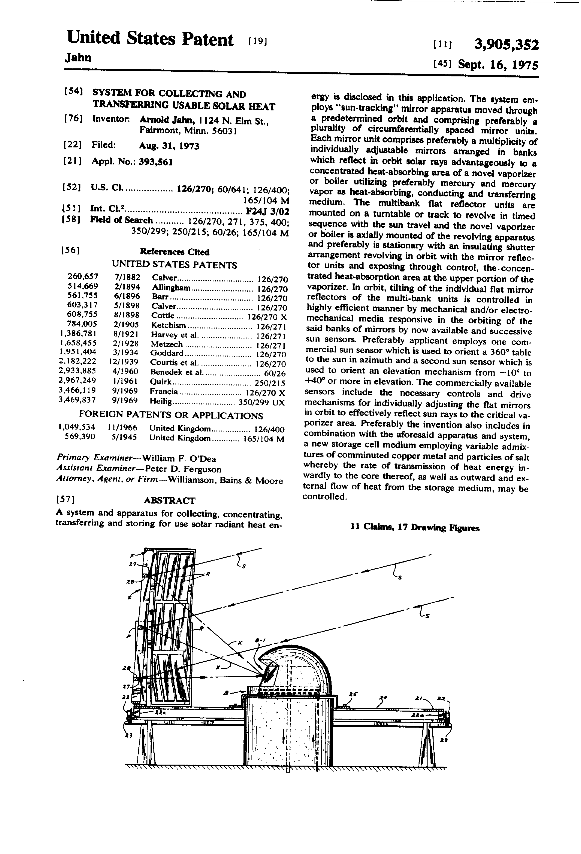
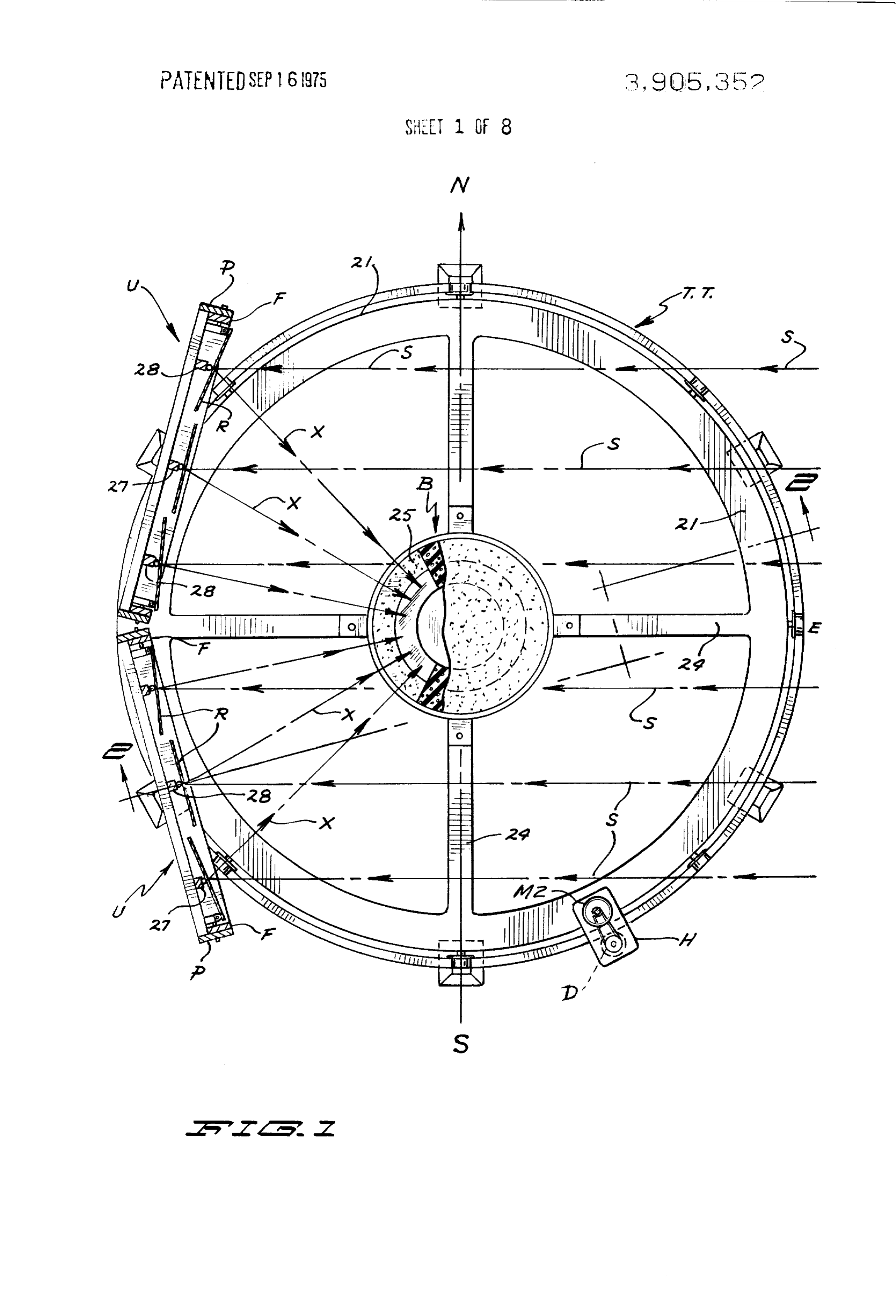
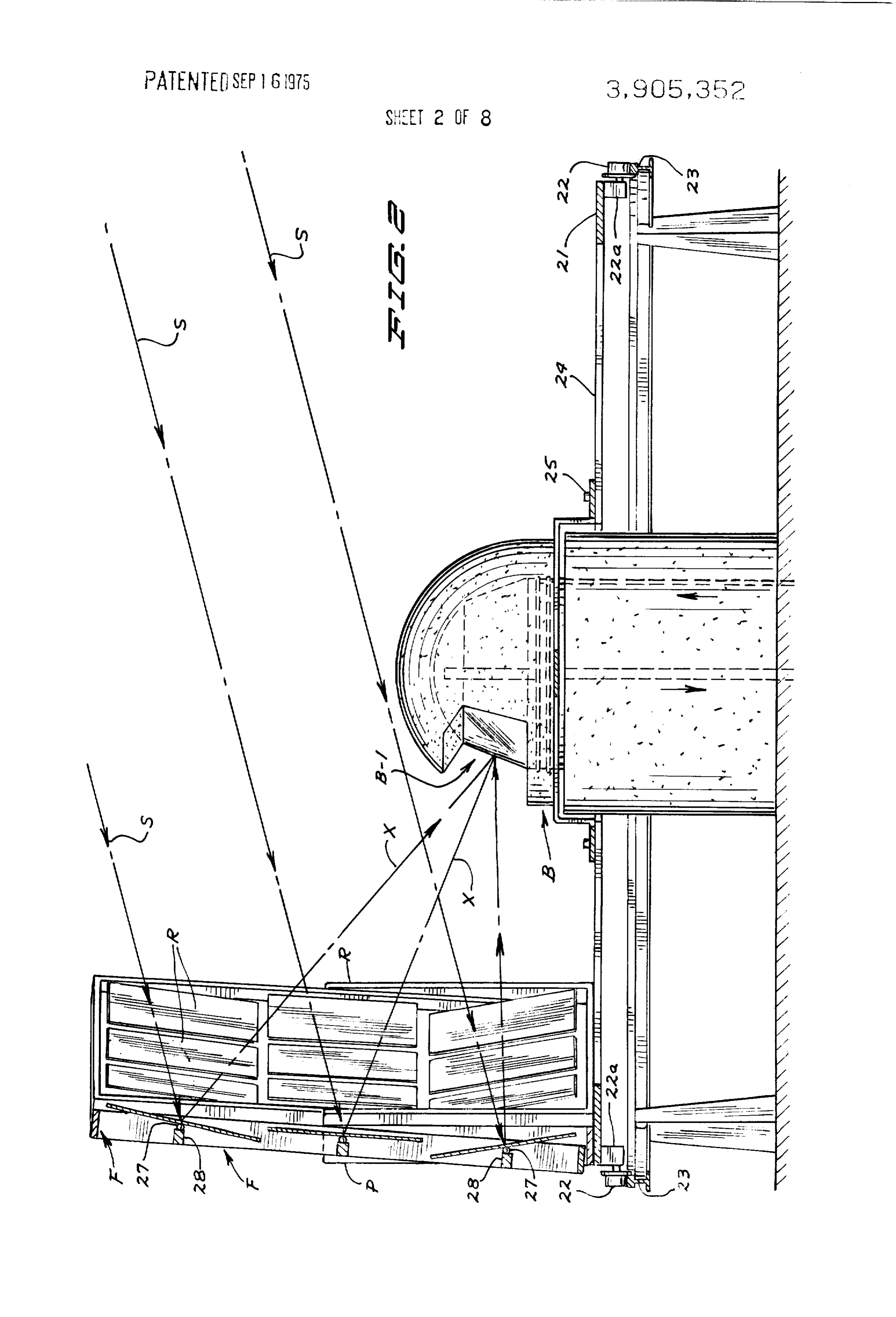
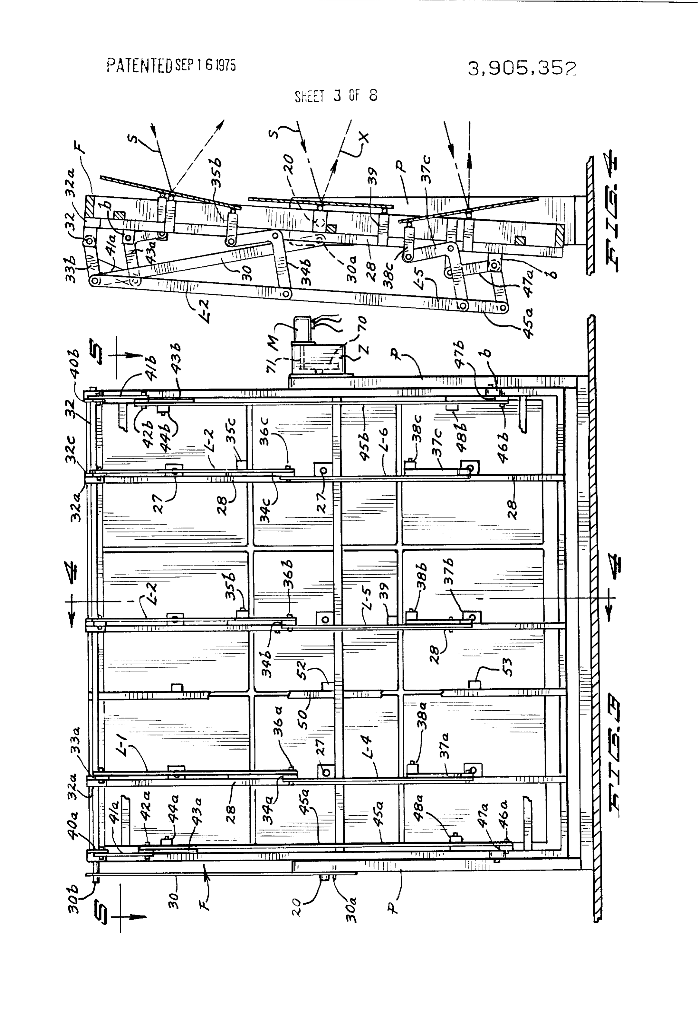
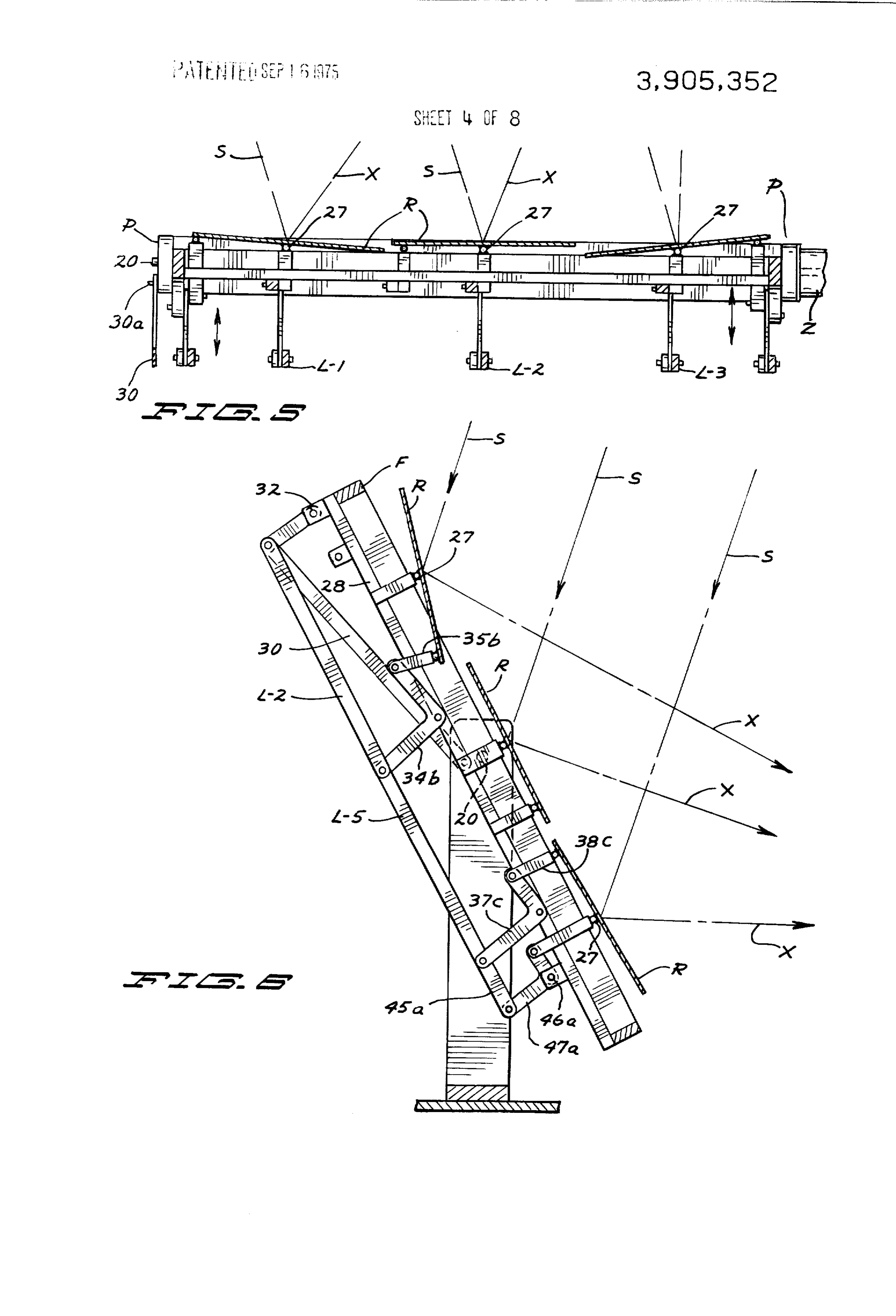
The structure, functions and advantages of an em 20 mounted in tiltable, large, rectangular frames F which bodiment of my invention will be apparent from the fol are supported for tilting by heavy trunnions 20 on hori lowing description made in connection with the accom zontal, transverse axes (see FIGS. 3 and 4) journalled panying drawings wherein like reference characters and supported from rigid, upstanding posts P having refer to similar parts throughout the several views and 25 the bases thereof rigidly secured to a turntable or sup in which: port surface TT mounted for revolution in clockwise FIG. 1 is a top plan view of the principal apparatus and The counter-clockwise direction.
revolving support for posts P and consequently (not including solar sensors or control and driving the multimirror units U, as shown, is in the form of a means and apparatus) for a somewhat simplified em turntable designated as an entirety by TT, which as bodiment of my invention; 30 shown includes a circumferential annulus 21 having at FIG. 2 is a vertical section taken on the jagged sec radially disposed intervals thereof bolsters 22a from tion line 2-2 of FIG. 1, showing the vaporizer or boiler which are rotatively mounted flanged supporting and one of the multi-mirror units in elevation; wheels 22. Wheels 22 rest upon and engage a circular FIG. 3 is a rear elevation on a larger scale showing a track 23 which as shown, is of T-rail construction. To part of the individual mirror-adjusting mechanism for 35 minimize weight of the turntable TT, spoke-like beams one of the multi-mirror reflecting units; 24 radially emanate from an axial and center hub struc FIG. 4 is a vertical section taken on the section line ture or ring 25 and are rigidly connected between said 4-4 of FIG. 3; hub structure and the circumferential annulus 21. As FIG. 5 is a horizontal section taken on the line 5-5 will later be explained, the turntable TT is motor of FIG. 3; driven either in clockwise or counterclockwise direc FIG. 6 is a vertical section similar to that of FIG. 4 tion, or in some forms may be revolved only in a clock but showing an elevational adjustment of the mirror wise direction.
unit and mounting frame and the positioning of the in Referring again to the multi-reflector units U, each of dividual mirrors when the sun in altitude is positioned 45 the flat mirrors R is centrally supported and mounted visually near the horizon, for adjustment on a ball and socket joint 27 disposed FIG. 7 is a plan view of the boiler or vaporizer of my at the very center of each mirror and which joint is sup invention; ported as shown by a vertical rigid bar 28 having its upper and lower extremities rigidly affixed to the top
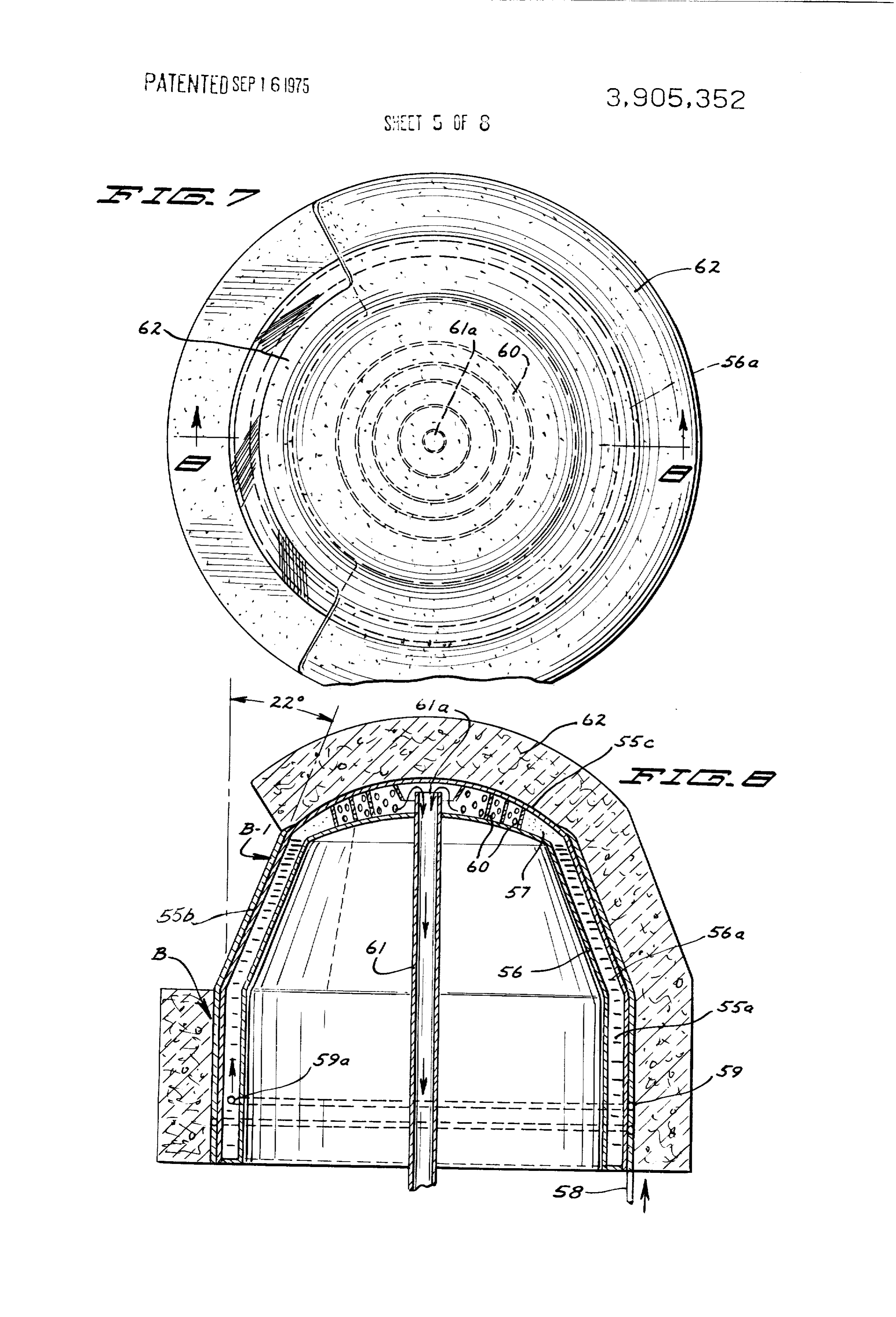
FIG. 8 is a vertical section along the line 8-8 of FIG. and bottom bars of the respective unit-rectangular 7; 50 frame F. For each of the two units U shown in the draw FIG. 9 is a diagrammatical rear elevation of a pre ings, nine square reflectors R are employed, arranged ferred multi-reflector unit showing the universal sup in very close juxtaposition in horizontal and vertical port connections for the individual mirrors, the pres banks.
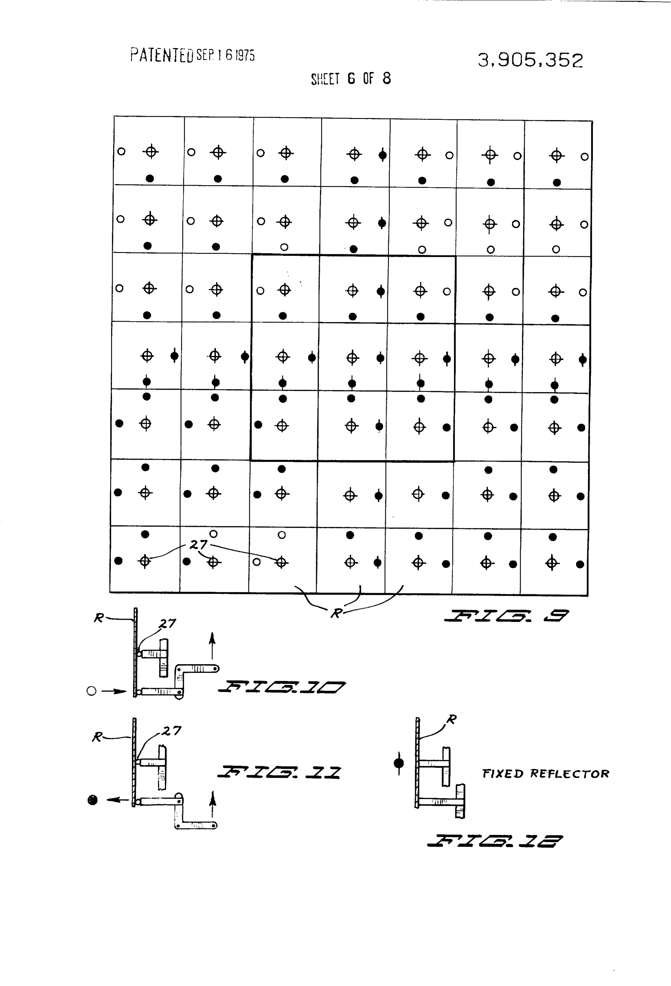
sure-applying points and the pull applying points for To facilitate understanding of the automatic adjust
ment mechanism for the multiplicity of individual mir
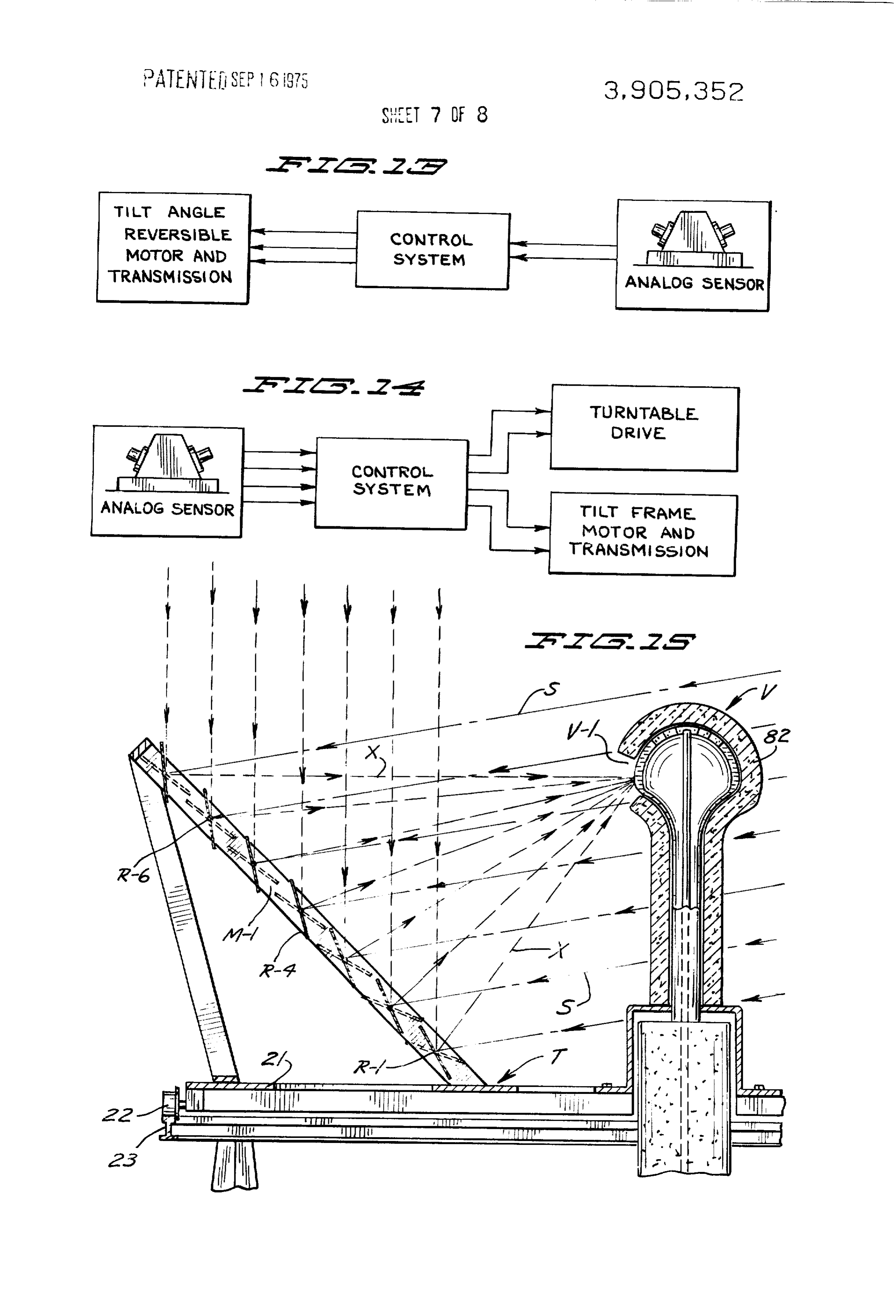
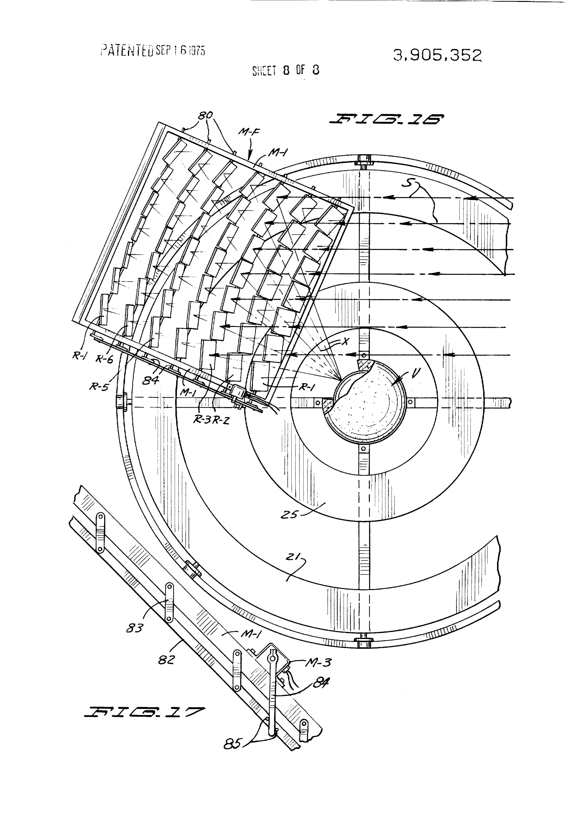
FIGS. 10, 11 and 12 show detail types or bell cranks rors in each unit U which immediately follows, there is and abutment means with corresponding symbols used the desirability to now recite a part of the operation of on FIG. 9 for mirror adjustment; the embodiment described, particularly referring to FIGS. 13 and 14 are schematic diagrams indicating FIGS. 1 through 6 of the drawings. In FIG. 1 the turnta control for driving means responsive to an analog sen ble TT and the two multiple mirror units U are shown Sor; in approximately the start of the sun tracking position FIGS. 15 and 16 constitute a vertical section and a where the location of the apparatus is at a geographical top plan view of a second embodiment of the invention; point in the United States between the latitudes 22 and and 65 45 during the late spring and early summer seasons. FIG. 17 is a detail elevation of a reversible drive for The solar rays shown in broken lines and arrows indi controlling oscillation of the several axles on which cated by the letter S, are emanating from the east at banks of mirrors are mounted. sharply acute angles to the horizontal. At such time
Page 12
S 6 through the sun tracking mechanism and control mech ing of the frame F in vertical shown in FIG. 4, approxi anism later to be described the large rectangular frames mates from 8 to 10 from the vertical while the approx of the two units of said embodiment are slightly tilted imate outward tilting of frame F with the sun at its high (from vertical positions) and incline toward the axes of est altitude approximates between 30 and 50 from turntable TT. The nine individual flat mirrors R of each vertical. The compass directions north, east, etc., are unit are respectively adjusted for most efficient recep indicated on FIG. 1 by the appropriate letters N, E, S, tion and reflection of the solar rays indicated along bro and W.
ken lines with arrows thereon, as X. In such adjusted The controlled tilting of the large rectangular frames positions it will be seen that most of the nine individual F is effected by suit able drive mechanism, later to be reflectors of each unit have experienced both horizon described, controlled by a solar sensor or a sun tal axis tilting and vertical axis tilting from planar posi tracking medium which responds primarily to the vari tions which are parallel with the perimeter of the large ance in sun elevation during the clockwise travel of rectangular mounting frames. turntable TT between sunrise and sunset. I have discovered that the sequential compound tilt Variable mirror-tilting-actuating mechanism, indi ing of all of the numerous mirrors of each reflective 15 cated as an entirety by the letter A, is interconnected unit U may be mechanically and efficiently controlled with the rear of the large rectangular mounting frame by the "elevational' tilting of the respective rectangu F and includes an elongate actuating link 30 (at the left lar mounting frames F of the two or more units, to most of the frame in FIG. 4) pivotally connected at its lower effectively reflect solar rays upon the exposed recep point by a pivot pin 30a to one of the rigid upstanding tive area of the centrally disposed boiler or vaporizer 20 posts P at a point disposed rearwardly and eccentric to B. First, I would explain that the medial horizontal the respective trunnion 20 on which frame F is pivot bank of planar mirrors R do not require change or ad ally connected with a post P for tilting on a horizontal justment in the tracking of the sun, either in respect to axis. The upper end of actuating link 30 is pivotally altitude changes of the sun's trajectory or in the hori connected by pin 30b with an upper rocker arm 31 af. zontal relative movement of the sun to the location of 25 fixed to a horizontal rock shaft 32 which is mounted in my apparatus. Thus, as shown in FIGS. 2, 3, 4 and 6, suitable bearings provided by blocks 32a affixed in the central mirror of the medial horizontal bank is fixed spaced relation to the several vertical socket support and remains in relation to its supporting large rectangu bars 28 (previously described). Rock shaft 32 extends lar frame F in a planar parallel relation relative to said transversely across the entire width of the rectangular frame. The mirrors R at left and right of said center 30 mirror frame F at the top thereof and in its oscillating most mirror R are fixed but are angled with respect to movement affected by the actuating link 30 one frame the centermost mirror (see FIGS. 4 and 5). Such angu F is tilted on a horizontal axis and controls and actuates lations are opposite on the said left and right mirrors on a series of (as shown) three vertical links L-1, L-2 and predetermined acute angles and the tilting is along only L-3 (see FIG. 4) by rocker arm connections with the the center up and down mid lines (see FIG. 5). Thus all 35 upper ends thereof. The respective rocker arms are in variance of the precalibrated and determined positions dicated by the numerals 33a, 33b and 33c. Links L-1, of the three mirrors of the central bank during tracking L-2 and L-3 at their lower ends are respectively pivot of the sun (both as to elevation and horizontal trajec ally connected with the outer ends of bell crank levers tory), is directly controlled by tilting of the large 40 34a, 34b and 34c (see FIGS. 3, 4 and 6). The fulcrum mounting frames F of the two units. pins for said last-mentioned three bell crank levers are The numerous mirrors R other than those of the hori respectively secured from left to right on FIG. 3 with zontal middle bank previously referred to will be vari the appropriate three of the vertical support bars 28. ably angulated and tilted relative to the general plane The working or upper ends of the said bell crank levers defined by the forward periphery of the rectangular 45 are pivotally connected with short forwardly protrud unit frame F, during the orbit of the reflector units in ing bars 35a, 35b and 35c, respectively, see FIGS. 3, 4 clockwise directional travel of the turntable TT. Some and 6, which at their outer ends carry ball and socket of such individual reflectors in the sequential adjust joints connected at lower vertical center line points ments tilt only on one axis while the four reflectors dis with the reflectors R of the upper horizontal bank, and posed at the corners within the rectangular mounting 50 said points are near the lower edges of said mirrors for frame tilt on two axes which intersect the respective tilting the same on horizontal axes. ball and socket joints for supporting the reflectors. The For tiltably adjusting the lower horizontal bank of said tilting-axes extending elevationally of the reflec mirrors on horizontal axes but in opposite swinging di tors for simplicity will be referred to as "vertical axes', rection from the tilting of the upper horizontal bank, while the transverse tilting axes will be referred to as 55 provide link and lever mechanism comprising three up "horizontal axes'. All sequential compound and single standing elongate links L-4, L-5 and L-6 having their axis tilting are mechanically effected by bellcrank lever upper ends pivotally connected, respectively, by pins action or the equivalent coupled with fixed point full 36a, 36b and 36c with both the lower ends of links L-1, crum pins in a system wherein relative actuating move L-2 and L-3, respectively, and also with the rearwardly ment is obtained through the elevational tilting of the projecting lower ends of the bell cranks 34a, 34b and rectangular mounting frame upon its rigid vertical sup 34c. Links L-4, L-5 and L-6 at their lower ends are piv porting posts P which will now be described in some de otally connected with the lower rearwardly protruding tail. First, by reference to the vertical cross sections of ends of bell crank levers 37a, 37b and 37c and said last one of the reflector units shown in FGS. 4 and 6, ap mentioned bell cranks are pivotally connected at their proximately the extreme tilting of the rectangular 65 fulcrum points with the same upstanding rigid support frame F is shown from the start (of approximate finish) bars 28 to which the upper series of bell cranks 34a, of sun tracking operation (FIG. 4) to the top or zenith 34b and 34c are connected. The working and upper position of the sun (FIG. 6). The maximum inward tilt ends of the bell cranks 37a, 37b and 37c are pivotally
Page 13
connected to short bars 38a, 38b and 38c, respectively, vidual mirrors. Such high capacity unit is preferred in which at their forward ends have ball and socket con commercial forms of the invention for use in electric nection with the upper edge portions of the lower hori power plants for towns, cities and the like. Symbols are zontal bank of mirrors, said connections being disposed employed in FIG. 9 for indicating the centermost ball upon the upstanding center line of said lower horizon and socket support joint for each individual mirror; the tal bank of mirrors. The foregoing linkage and bell connection by short bars with the working ends of two crank mechanism during the variable tilting of the large types of bell crank levers and such symbols in FIGS. 10 mirror mounting frame F sequentially actuates all tilt to 12 inclusive are related to diagrammatic views of the ing adjustment of the three banks of mirrors on their respective connection. It is to be understood that pref horizontal axis as is required for successful operation of erably the connection of each short bar at the working my apparatus and system. It should be noted that all of ends of the respective bell cranks provides a universal the individual mirrors of the upper and lower banks in or ball and socket joint. Thus, while as previously ex the embodiment illustrated receive variable tilting plained, some of those connections are with vertical or movements on horizontal axes. The upper and lower horizontal edges of a mirror to restrict and prevent tilt mirrors of the vertical middle bank receive, in opera 15 ing on one axis, they will permit tilting on an axis per tion, only tilting on their horizontal axes. The central pendicular thereto unless a second fixed connector is horizontal bank of mirrors, as previously recited, re employed. The nine central mirrors, border outline of ceive no adjustment but are stationary in their origi which is heavily shown, represent the nine mirrors illus nally positioned relation, the centermost being parallel trated in the first embodiment of the invention. By in with the plane defined by the front of frame F. To fix specting the symbols employed in the respective mir this centermost mirror in said position, means is pro rors of FIG. 9 and understanding the significance of the vided, such as a fixed post 39, secured to the central connections, the multiple tilting adjustments and single vertical support bar 28 and having a fixed connection tilting adjustments of the individual mirrors can be de with said centermost mirror. The two mirrors at left termined. It should be significant that even with the and right of said centermost mirror are predetermina 25 large multiplicity of mirrors used in the diagram of FIG. bly, by calibration, angled oppositely toward the cen 9, all progressive adjustments can be obtained through termost and fixed in such angulation (by means not simple vertical link connections with the essential bell shown). cranks. All of such adjustments are progressively con The four cornermost mirrors of the assembly are also 30 trolled by powered oscillation of the top transverse actuated by link and bell crank mechanism on vertical rock shaft 32 which actuates by the rock bars, the sev axes (lines extending upwardly through the center eral linkage and bell crank connections. It will, of points of said corner mirrors) as will now be described. course, be understood that various equivalent, mechan Adjustment movement is provided again by the oscilla ical or electrical operating means may be substituted tion of elongate top rock shaft 32 through right and left 35 for the embodiment disclosed all within the scope of endmost rocker arms 4.0a and 40b (see FIG. 3). Short applicant's invention.
depending links 41a and 41b are pivoted at their upper It will be noted (see FIG. 2) that where two or more ends to rocker arms 4.0a and 40b and at their lower multiple reflector units are employed, the horizontal ends are pivotally connected by pins 42a and 42b with axes of the two oscillatory frames F instead of being the upper rearwardly projecting ends of bell crankle 40 precisely perpendicular to radii of the boiler B extend vers 43a and 43b, respectively. The fulcrums of said at oblique angles slightly of about 15 to 20 therefrom. last-mentioned bell cranks are pivoted to suitable This provides for proper calibration of the tilted posi blocks baffixed to the left and right hand vertical sup tions of the multiple of mirrors in the two units to pro port bars 28. The depending and working ends of the vide for efficient reflection of solar rays on the expo bell cranks 43a and 43b are pivoted to forwardly ex 45 sure of the boiler without crossing of such reflected tending short bars 44a and 44b, respectively, which at rays from the two units.
their forward ends have ball and socket connections As a means to restrict the vertical central bank of near the vertical outer edges of the corner mirrors of mirrors from tilting on upstanding or vertical axes, the upper horizontal bank. So connected, tilting adjust provide as shown (see FIG. 3) a rigid, upstanding bar ment of the two upper corner mirrors on vertical axes 50 50 affixed to the general frame F of the unit having will be in opposite directions. spaced blocks 51, 52 and 53 disposed on the horizontal The corner mirrors of the lower horizontal bank are axes of the central vertical bank of mirrors, and which similarly actuated and tilted on vertical mid-axes. To blocks have at their outer ends ball and socket connec such ends, elongate upstanding links 45a and 45b are tion with the left hand edges (see FIG. 3) of said three pivotally connected at their upper ends with the rear 55 mirrors.
wardly projecting arms of the bell cranks 43a and 43b It is of course to be understood that in the original and their lower ends are pivotally connected by pins calibration and setting of the apparatus the mirrors to 46a and 46b with the rearwardly extending lower arms the left and right of the central vertical bank will have of bell cranks 47a and 47b, respectively. Said last predetermined angular adjustments tilted on mid-line mentioned bell cranks are fulcrumed on blocks baf vertical axes. The corner mirrors of the nine illustrated fixed to the left and right rigid side members of the will have predetermined angular relations also tilted on mounted frame F. The working ends of said bell cranks horizontal axes as previously described. After the fixed 47a and 47b are pivotally connected to short blocks angular relations, the entire progressive adjustments 48a and 48b which at their outer ends have ball and for varying elevation of the sun as well as for variance socket connections with the outside vertical edges of 65 in the horizontal component of the sun's trajectory, are the corner mirrors of the lower horizontal bank. controlled by the described linkage and levers entirely In FIG. 9 a diagrammatic elevational view is shown by the overall tilting of rectangular frame F. Such tilt of a high capacity multi-mirror unit comprising 49 indi ing and the reverse tilting is progressively and effi
Page 14
ciently controlled by suitable mechanism and means to boiler body. The other portions internally of shroud 62 be described. are spaced a slight distance outwardly of the exterior of The said controls provide for, as shown, motor the boiler body and a segmental generally rectangular driven reversible tilting of the frame by electric motor portion of the shroud 62, as shown in FGS. 2 and 8, is and transmission mechanism mounted on one of the cut to form an exposure opening, indicated as an en heavy, upstanding support posts and control of the cir tirety as B-1. Shroud 62 is affixed to the hub portion of cuitry and reversibility of the motor by a conventional turntable TT and is revolved therewith. heliostat or sun sensor. The height of the boiler B and particularly the height BOLER OR WAPORIZER STRUCTURE of the exposure area B-1 is such, that taking into con O sideration radial distance from the exposure area B-1
Referring now in some detail to the heat-absorbing to the centermost fixed mirror of a unit, reflected solar boiler or vaporizer indicated as an entirety previously rays at sunrise will strike the center of exposure area of as letter B, the base and lower portion of the boiler the boiler, and consequently the calibrated, predeter body, indicated as 55a, comprises a cylindrical shell mined starting position of all of the mirrors of the unit continuing in an upper truncated conical portion 55b 15 will reflect solar rays to said exposure area. and a doned heat 55c (see FGS. 6 and 7). The entire The walls of boiler B may be constructed of conduc outer body structure is preferably constructed of a tive metal such as stainless steel or copper. The exterior metal or metal alloy such as copper having very high of the shell portion 55 is densely covered with non heat conductivity. This entire shell, indicated as S5, is reflective, heat-absorbent material such as an efficient disposed in spaced relation to an inner metal shell of 20 "black'.
similar contour and shape, 56, forming in its spaced re lation a rather narrow annular chamber closed at its CONTROLLED OSCILLATION OF MIRROR-UNIT lower edge and communicating at its upper edge with FRAME the interior of a circular vapor chamber 57 (see FIG. While it will be understood that numerous means and 8). The lower portion of the overall boiler body, as 25 mechanism may be successfully utilized for progres shown in FIG. 2, extends below the level of the turnta sively tilting the rigid mounting frame F of each multi ble TT, the upper portion including most of the trun mirror unit, the means and mechanism illustrated cated conical configuration 55b and the upper dome somewhat diagrammatically in FIG. 3 comprises the 55c projects some distance above the turntable to ex following: The heavy righthand trunnion 20 journalled pose unshielded segmental portion of the truncated 30 on the horizontal mid-center line is provided with a area which is designated as the exposure portion of the fixed worm gear 70 which is meshed with a relatively boiler B-1. very small worm 71 affixed to the power takeoff shaft The entire boiler structure perse is stationary and ax of a reduction gear mesh mechanism. Said mechanism ially disposed of the turntable TT within the confines with an electrical motor M. is housed within a case 73 within the hub-like annulus 25 of the turntable. 35 rigidly affixed to the upper portion of the righthand Mercury in liquid form is flowed by pump or liquid supporting post P (in FIG. 3). The motor is a reversible head to an inlet 58 in the direction shown by the arrow motor designed for almost instant starting and stopping FIG. 8 through a helical coil 59 surrounding the exte and the circuitry from said motor is controlled from a rior of the lower portion 55a of the boiler body, and 40 remote control box, circuits of which are responsive to communicating at its upper end through a passage 59a a SU SeSO.
with the annular chamber 56a of the boiler body. This Generally speaking, when frame F is positioned, as annular chamber is very effectively heated by the re shown in FIG. 4, swung inwardly from vertical position flective solar rays striking the exposure portion B-1 at about an 8 to 10' angle the individual mirrors are thereof, and the mercury in said chamber is mostly in automatically positioned to receive the sun's rays in ap vapor form, arising to the dome circular chamber 57 in 45 proximately sunrising position with the solar rays ex the top portion of the body. The vapor, containing tending at an acute angle of about 15 to the horizon. sometimes liquid and in some instances small globular The mirror units, turntable mounted, will then, by particles, is further heated in the highest temperature mechanism hereinafter to be described, be related on dome of the boiler and passes through a series of aper SO the turntable track for effectively tracking the sun. As tured striker plates 60 transversely disposed of the the sun rises to its highest elevation on the particular dome chamber 57 which have the effect of skimming day, the unit frame F will be progressively oscillated liquid and which are intensely heated to vaporize any under circuitry control of the motor to a maximum few globules of mercury not yet vaporiscd. The vapor tilted position approximately as shown in FIG. 6 of from the dome circular chamber 57 passes downwardly 55 from 42 to 50 tilting backward from the vertical (de axially of the boiler at the hottest point of the dome pending of course on the season and the particular day therein through the inlet 61a of a vertical and axial of operation). Thereafter, as the path of the sun de vapor tube 61 from the lower end of which it is distrib clines, operation of motor M will be reversed by con uted and transferred to a collector, storage medium or trol to progressively return by oscillation the frame to other medium connected with and constituting a part approximately the original starting position at the set of the overall energy system. ting of the sun.
Closely cooperating with the dome and body of va DRIVING AND CONTROL OF MOUNTING porizer B is a thick insulating shroud or cover 62, as PLATFORM shown rigidly secured at its base to the central hub-like portion 25 of the turntable. The material of the insulat 65 While sophisticated, sun sensor control means may ing shroud 62 has exceedingly high heatinsulating prop be provided, as schematically illustrated in FIG. 14, to erties and at its top interior, indicated as 62a, is in light progressively apply driving power to the turntable TT, contact with the top of the dome portion 45c of the prefer to utilize for simple driving and control thereof
Page 15
(as schematically shown in FIG. 1) the following mech sor, for example, may be commercially purchased from anism and controls: Adcole Corporation of Waltham, Massachusetts, and One or more identical reversible motors M-2 me the type of sensor known as a heliostat having an ana chanically drive connected with predetermined, reduc log output is satisfactory for use with the system sche tion gear transmission mechanism are mounted in suit matically shown in FIG. 13, as well as FIG. 14. In FIG. able heavy housings H rigidly affixed to the outer rigid 13 the output of the analog sensor connects with elec annulus 21 of the turntable TT. The output shaft of trical circuitry constituting a part of the system con such mechanical transmission carries a heavy friction tained in the “control" block of the drawings which by drive roller D which frictionally engages the external relay, solenoid or otherwise will actuate switching side of track 23. Speed adjustment of the transmission O mechanism to the reversible motor for actuating the el mechanism or other satisfactory control of the driving evational tilting of the rectangular frame F of a multiple speed and ratio of the turntable is provided so that if no mirror unit. FIG. 13 schematically illustrates the sim reversing of the electrical motors is interposed the turn plest use of a sun sensor to sense sun angle or elevation table would make a complete revolution throughout a and where this system of FIG. 13 is utilized the simplest 24 hour time cycle. 15 means of predetermining by operator control the start However, since in substantially all latitudes of the ing position of the sun track of the turntable TT is en earth the sun's rays for different days of the year are ployed, as described in pages 19-20 thereof. only available for varying and predetermined hours and Referring to the schematic showing of FIG. 14, the minutes, the varying rotative travel and starting point sun sensor here and its output is responsible for operat of the turntable with the multi-reflector unit or units ing two control system phases. The function of control mounted thereon are for each day during the year ling circuitry for the elevational tilting of the large rect pushbutton controlled. angular multi-mirror frame is similar to the circuitry To such ends calibrated graduations and indicia may and control shown in FIG. 13.
be supported or suspended below the stationary track 25 In addition, however, the sensing of the sun during its 23 showing starting points of the apparatus for the nec variable trajectory from sunrise to sunset in a generally essary change day-by-day or multiweekly times for the horizontal direction is detected by the analog sensor apparatus. and is responsive to circuitry for controlling off and on Apparatus of the complexity required in simple form of the turntable driving means.
normally should require supervision of a trained em 30 Since heliostats with cooperating circuitry and drive ployee. This employee, each day after sundown or be means are well known in the art as maufactured and fore sunrise, by push-button would reverse the driving sold by Adcole Corporation of Waltham, Massa motor or motors for the turntable and, if desired, simul chusetts, and by Carson Astronomical Instruments, inc. taneously shift gears in the transmission to substantially of Valencia, California, the foregoing description and accelerate reverse or counterclockwise revolution of schematic views are deemed adequate. the turntable. When the turntable returns to the start 35 PREFERRED HEAT-STORING MEDUM ing position shown for the next calendar day or the next starting position, the operator would de-energize the For continuously or intermittently receiving transfer motor circuitry and the apparatus would be in starting of heat and storing the same, I prefer to employ a re position for the rising of the sun the next day. A time ceiving and storing medium consisting in a dense filling controlled switch may be used to control the normal or admixture of copper particles and ordinary salt gran driving of the motors at sunrise of the next day. ules (NaCl). These ingredients are intimately admixed It will be understood that an external stationary bull and substantially fill a large casing or housing con gear may be affixed to the lower portion of the circular structed of highly efficient heat-insulating material rail or track 23 and a positive pinion drive. D substi 45 such as, for example, a wall thickness of 12 inches of tuted for the friction driving element, or that any equiv asbestos or vermiculate. Particle size of the salt and alent and more efficient predetermined speed driving copper ingredients preferably would run from 100 to means may be employed controlled in operation by a 300 microns in largest dimensions. A heat-transferring time control switch or other means for opening the coil or the equivalent of a highly conductive metal, motor circuit. such as stainless steel or copper, is submerged in the It will also be understood that the respective weights said filler material and its intake end is connected with of the two reflector units and their mounting frames the output of the very high temperature mercury vapor and actuators will be counterbalanced in the opposing or other fluid discharged through the axial tube of the circumferential structure of turntable TT partially by boiler B shown in FIG. 8. One or more additional coils, the driving motor or motors M-2 and partially by the 55 boilers or other heat-transfer means may also be em addition of the heavy material or counterweights to bedded in the said storage medium and connected at perfectly balance the turntable and facilitate somewhat their intake ends with vapor or liquid lines for generat revolution thereof on the supporting track 23. ing steam or hot fluids by passage through the storage The driving and control of the turntable TT, where unit. The flow of fluid through such lines may, of sun tracking mechanism dictates control, will be de course, be controlled for use as needed for the supply scribed later herein. of steam for turbines which in turn may drive electrical generators.
CONTROL SYSTEMS RESPONSIVE TO SUN My experimentation with the said particulate copper SENSOR OR HELIOSTAT and salt for heat-storage material has shown that a pref Referring first to the schematic illustration of FIG. 65 erential range of proportions by volume of from 20% 13, a suitable conventional sun sensor, entitled in the to 40% copper with the balance NaCl. block "analog sensor', is employed, which preferably With my system as described, and efficiently insu is of the type affording sun angle sensing. Such a sen lated conduits from the boiler to the heat-storing me
Page 16
dium, transfer of heat should produce temperatures grammatically shown in FIG. 16. In considering the slightly in excess of 1400 of residual heat stored in the said angulations expressed, it should be noted that the material. I have discovered that ordinary salt has unex longitudinal center line of mounting of the entire unit pectedly high heat-retention abilities and mixed with does not extend at 90 to a radius from the vaporizer the highly conductive copper particles is productive of 5 V but is purposely disposed somewhat obliquely to said an economical heat-retention and storage unit. radius. The leading end of the reflector unit during rev A SECOND EMBODEMENT OF THE INVENTION olution of the turntable T extends outwardly some dis tance further than the trailing end as in the embodi
In FIGS. 15 and 16 of the patent drawings, a second ment first described.
and somewhat simplified embodiment of the invention O In FIG. 15 the full line cross sectional representations is illustrated wherein the multiplicity of preferably flat of the mirrors are in the positions of start of operation reflectors are mounted in horizontally extending con at sunrise while the dotted line cross sectional elements tiguous banks and on successive horizontal tilt axes. In indicate angular tilting of the mirrors by oscillation of stead of mounting and supporting the said banks of mir the axles 80 at the highest elevation of the sun's trajec rors upon an elevationally tiltable frame, their succes 5 tory for a predetermined day or period. sive axes from bottommost bank to uppermost are ar The relationship of predetermined angulation of the ranged in parallel 'stadium' relation to the central part seven mirrors of the other horizontal banks is similar to of the turntable, and in operation no tilting variation of the positions and angulations shown in cross section in any mirrors on upstanding (vertical) axes is needed to FIG. 16, but of course it will be understood that the properly focus all of the mirrors during tracking of the 20 banks of mirrors extending successively upward from sun through its daily trajectory. A central upstanding the central mirror will be predeterminately tilted on and axial vaporizer V is employed having an exposure horizontal axes relative to the mirrors of the central area V-1 which has its center disposed in height slightly horizontal bank as shown in FIG. 15 in cross section. (within a range of 2 to 6) below the horizontal centers It will be understood that in the original calibration and of the uppermost bank of tiltable mirrors. 25 setting of the apparatus, the mirrors to the left and right While only one multi-reflector unit is shown in the of the central vertical bank will have predetermined an drawings, it will be understood that two or more units gular adjustments tilted on midline upstanding or verti working in close cooperation may be employed. The cal axes. The individual mirrors of each bank are fixed turntable, designated as an entirety by T, is mounted at predetermined tilted angulation to their respective similarly to the turntable of the first embodiment and axes, and when the apparatus is set up variable oscilla is supported on heavy tracks 23 by a plurality of tion of the respective axle shafts 80 is predetermined to flanged wheels 22 which are journalled in bolsters 22a cause all mirrors to focus on the exposure area V-1 of depending from and rigidly attached at circumferen the vaporizer at the start of the cycle of operation at tially spaced points to the outer concentric annulus 21 sunrise. Various means of interconnection of the seven of the turntable. 35 spaced axles 80 may be employed and for simplicity I A rugged and rigid rectangular mounting frame, indi have shown the axles in the form of oscillatory rock cated as an entirety by MF, is rigidly supported and af shafts with corresponding left ends thereof having fixed circumferentially in an inclined relation to the properly affixed thereto a rocker arm 83. The rocker general horizontal surface of turntable T and extends arms are respectively affixed to shafts 80 for variable planarwise at an angle approximating 45 (range be 40 angulation in perfectly focusing the mirrors during all tween 40 and 50) to the top turntable surface. The parts of the cycle of operation and, as shown, are actu successive elongate axles 80 for the several horizontal ated by longitudinal reciprocation of an actuating bar rows or banks of reflector mirrors are suitably jour 82 which is disposed in substantially parallel relation malled in bearings provided by the rigid inclined end with one of the frame ends M-1, as shown in FIG. 17. members M-1 of the mounting frame with the result 45 The lower ends of each of the rocker arms 83 has piv that the several axles 80 of the successive banks are in otal connection with actuating bar 82 and this bar may parallel relationship at differential distances from the be longitudinally reciprocated by a rigid arm 84 affixed exposure area V-1 of the vaporizer V. As shown, sev to power takeoff shaft of the transmission mechanism eral horizontal banks of mirrors (seven) are employed, driven by a reversible motor M-3. The outer and free being respectively numbered from the lowermost to the end of actuator arm 84 works between a pair of pins 85 outer and uppermost as R-1 through R-7. As shown, affixed to the lower portion of the bar 82. seven planar mirrors are employed in each horizontal bank. SUMMARY A simple axle means, in the form of a rigid shaft 80, From the foregoing description and drawings it will is employed for mounting the seven mirrors of each 55 be apparent that my discoveries will produce a maxi bank with the ends of said shaft being journalled in suit mum direct reflection and concentration of solar rays able bearings provided in the inclined side members upon the heat-absorption or exposure area in relation M-1 of the mounting frame. The several mirrors of to the cumulative reflective area employed. Such new each bank are rigidly affixed by suitable means to the 60 and improved results are obtained through the combi respective axle shaft 80. In this connection the surface nation of components or factors which include the or of the centermost mirror is parallel to the axis and each bital travel of one or more multi-reflector units having successive mirror of the bank at both sides of the cen individual reflective surfaces which are varied angu tral mirror is predeterminately angled as shown and di larly or tiltwise in cycle of operation through suitable agrammatically indicated in FIG. 16. The successive 65 operating connections actuated in response to conven angulations to the plane of the central mirror on the tional sun sensors. The cooperative functioning of the specific embodiment disclosed in FIGS. 15 and 16 is multi-reflector units or unit with the axially disposed indicated in degrees on the cross sectional areas dia heat-absorbent portion of the boiler and the relative
Page 17
heights thereof cooperate in combinative manner to and also on axes extending perpendicularly to said produce the said maximum concentration and direct horizontal axes, and reflection. With two or more multi-reflector units dis actuator driving means connected between said tilt posed generally end-to-end in the somewhat oblique ing frame and all of said individual reflector ele positions to radii, the height of the units as contrasted ments, with the exception of those elements ex with anything in prior art is substantially lessened, tending in said central rows, for variably tilting and The new functioning and operation of my system or oscillating said non-excepted reflector elements on apparatus can be said to split the angle of solar rays (to both horizontal and transverse axes to cause all of horizontal), and direct reflection with maximum con said non-excepted reflectors during cyclical opera centration is obtained without additional or intervening O tion of said system in response to tilting movements parabolic or other reflective devices interposed in the of said frame to constantly focus upon said expo overall reflective cycles. Thus in the highest seasonal sure area of the generator. elevation of the sun in the zenith the downward vertical 2. The system and combination set forth in claim 1 rays will be split and reflected with the majority of the 15 wherein said actuator driving means includes a substan mirrors tilted on horizontal axes disposed and arranged tially horizontal rock shaft oscillated by movement of between 38 to 50' angulation to the horizontal. said tilting mounting frame, and rocker arm linkage be While I prefer to utilize from my individual reflectors tween said rock shaft and said individual reflectors. planar rectangular surface reflectors, it will be under 3. The structure and combination set forth in claim stood that my invention is in no way limited to the same 20 1 wherein said horizontally extending rows of reflectors and that dished or somewhat parabolic or segmental are successively disposed one above the other and cylindrical reflectors may be employed with, of course, above said unit supporting device and wherein the posi the necessary affixation and calibration required to tional relationship of the exposure surface of said gen focus solar rays directly upon the heat-absorption me erator and the focus center line of said reflector unit, dium or area. 25 when the upper periphery of said unit is in uppermost
It will also be understood that the interconnection of position, extends substantially axially through the cen individual reflectors in each unit or interconnection of ter of said exposure area.
oscillatory axis in the second embodiment of my inven 4. The system and combination set forth in claim 1 tion may be conventionally varied with equivalent link wherein, age and interconnection to operate and be actuated in a fluid conduit medium is mounted within and consti the general system disclosed. tutes a part of said generator and includes a dis It is to be understood that the terms "variable tilt charge connectible with a heat-storage or heatutil ing', “angularly tilted" or "tiltable' utilized in the izing system.
claims shall be construed broadly to include tilting of 5. The system and combination set forth in claim 1, the individual reflectors both on axes extending up 35 and additional driving means between said tilting frame wardly through the midlines or on axes extending on and the individual reflector elements of said central horizontal midlines, as well as to tilting of the mirror or transversely arranged row of elements for variably tilt mirrors on either of said axes per se. ing said elements only on axes disposed transversely of What is claimed is: the horizontal to cause such reflectors, responsive to 1. In a system for collecting and transferring solar 40 tilting of said frame, to constantly focus upon exposure heat energy which employs a reflector unit-supporting area of the generator during cyclical operation of said device moved in orbital travel through a curvilinear system.
path: 6. The system and combination set forth in claim 1, a multi-reflector unit comprising a multiplicity of in wherein no tilting driving means are supplied for the dividual reflector elements predeterminately ar 45 central row of reflector elements extending horizon ranged in a group area, tally but wherein said elements are successively perma an upstanding mounting frame wherein said multi nently set on different angulations relative to the gen plicity of reflector elements are supported for vari eral plane defined by said frame to constantly focus able angular tilting functions during cyclical opera 50 upon the exposure area of the generator due entirely to tion of said system, the elevational tilting of said frame in cyclical opera means for mounting said frame on said unit tion of said system.
supporting device with freedom for tilting oscilla 7. The system and combination set forth in claim 1, tion on a horizontal axis disposed centrally of said wherein the elevational tilting of said frame and the
mirrors contained therein respond to approximately reversible driving means controlled by a sun sensor one-half of the elevational variance of the sun during for tilting said frame in synchronism with eleva the day between sunrise and sunset and wherein the tional variance of the sun in a daily cycle, variable tilting of the individual reflector elements with a solar ray absorbing generator having an exposure the exception of those elements extending in said cen area disposed axially of the orbit of said supporting tral row through said actuator driving connections re device, spond to the other half of the variation in elevation of the reflector elements of said group area being ar the sun during the day.
ranged and mounted in a series of generally hori 8. The system and combination set forth in claim 1, zontally extending rows and in a series of trans wherein said solar ray-absorbing generator is stationary versely extending rows, each of said series having 65 and is disposed at a level above the lowermost marginal a centrally disposed row, area of said frame in all swinging movements thereof means for mounting said individual reflectors for and below the uppermost positioning of said frame in freedom of oscillatory tilting on horizontal axes all swinging movements thereof.
Page 18
9. The system and combination of preceding claim 8 a stationary solar heat generator having an upstand wherein said generator has a generally partial spherical ing stationary external exposure surface disposed surface at the upper portion thereof, axially of the travel orbit of said supporting device a shroud and shielding member constructed of heat and having a symmetrical shape which is circular in insulating material covering most of said exposure horizontal cross section, area of said heat generator and having an exposure a shroud and shielding member of shell shape com window area through which reflected solar rays plemental to said exposure surface constructed of may pass, and means interconnecting said shielding member with heat-insulating material and movably overlying and said reflector supporting device for causing said 10 covering said exposure area of said heat generator shielding member to revolve about said generator and having an exposure window area through during orbital travel of said supporting device. which reflected solar rays may pass, and 10. A system for collecting and using solar energy means interconnecting said shielding member with having in combination: said reflector supporting device for causing said a reflector-supporting device powered for orbital 5 shielding member to revolve about said generator travel through a substantially circular path defining during orbital travel of said supporting device. generally a horizontal plane, 11. The structure and combination set forth in claim a reflector unit mounted on said supporting device 10 wherein said external exposure surface of said gen for swinging oscillation on a substantially horizon erator is substantially spherical and wherein said tal axis, upwardly and downwardly, 20 shroud and shielding member is substantially semi controlled means for propelling said supporting de spherical.
vice through said orbital path, sk is is k
Provenance
- Collection
- Cited prior art
- Original PDF
- patentimages.storage.googleapis.com →
- Filed
- 1973-08-31
- Pages
- 18
- Method
- pdftotext (the PDF's own text layer) + pdftoppm 300dpi page scans
- Source
- Google Patents bibliographic record
- Granted
- 1975-09-16
- Inventors
- Arnold Jahn
- Transcribed from
- patentimages.storage.googleapis.com →