patent · US3884217
Method and apparatus for collecting solar energy
20 May 1975
Page 1 — bibliographic record
United States Patent (19) [11] 3,884,217 Wartes (45) May 20, 1975
54) METHOD AND APPARATUS FOR
COLLECTING SOLAR ENERGY Primary Examiner-William F. O'Dea 75) Inventor: Lloyd Lore Wartes, Denver, Colo.
Assistant Examiner-Peter D. Ferguson
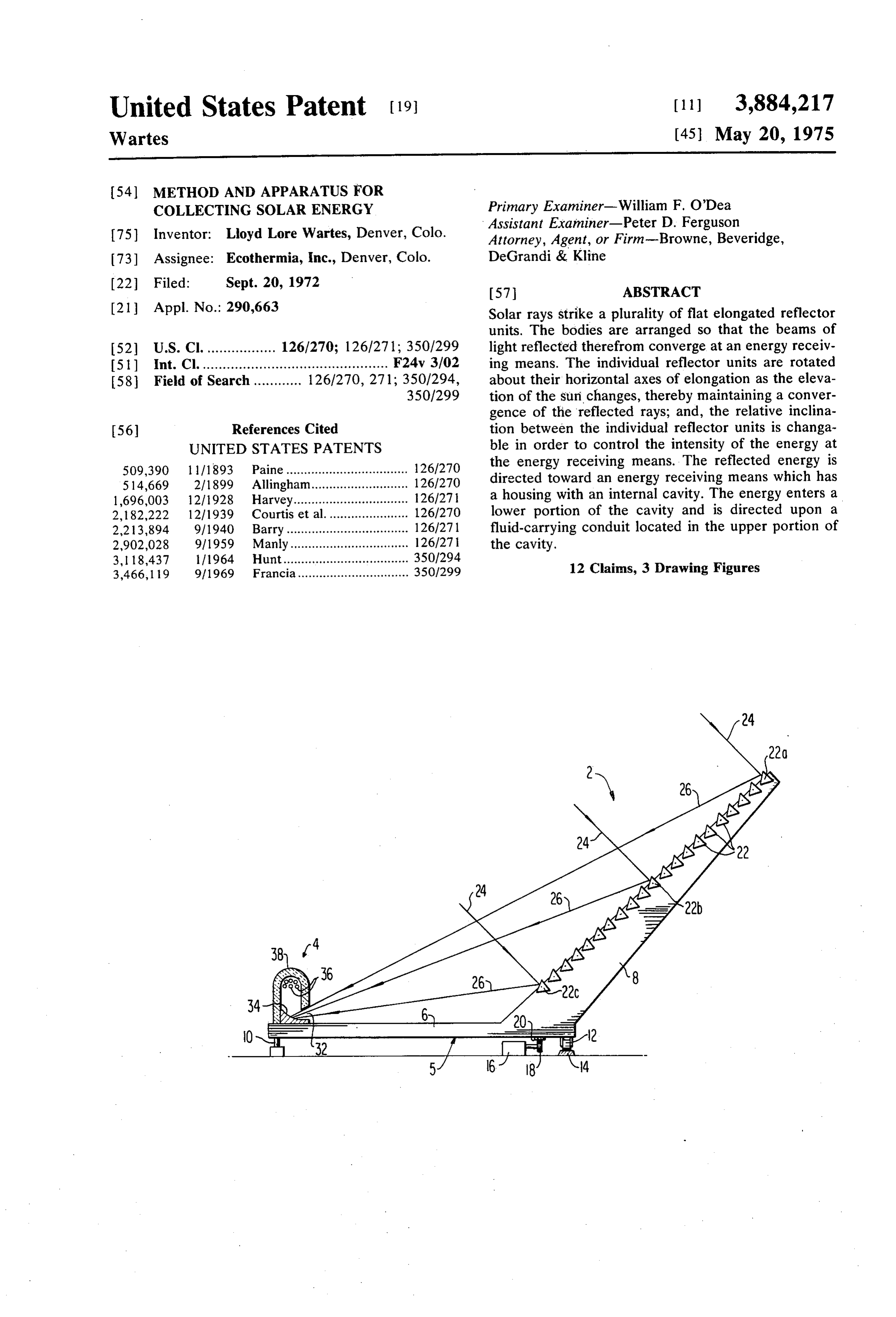
Attorney, Agent, or Firm-Browne, Beveridge, 73) Assignee: Ecothermia, Inc., Denver, Colo. DeGrandi & Kline 22 Filed: Sept. 20, 1972 57 ABSTRACT 21 Appl. No.: 290,663 Solar rays strike a plurality of flat elongated reflector units. The bodies are arranged so that the beams of 52 U.S. Cl. ................. 126/270; 126/271; 350/299 light reflected therefrom converge at an energy receiv 51) Int. Cl. .............................................. F24v. 3/02 ing means. The individual reflector units are rotated 58 Field of Search ............ 126/270, 271; 350/294, about their horizontal axes of elongation as the eleva 350/299 tion of the sun changes, thereby maintaining a conver gence of the reflected rays; and, the relative inclina 56) References Cited tion between the individual reflector units is changa UNITED STATES PATENTS ble in order to control the intensity of the energy at 509,390 1 1/1893 Paine.................................. 126/270 the energy receiving means. The reflected energy is 514,669 2/1899 Allingham........................... 126/270 directed toward an energy receiving means which has 1,696,003 12/1928 Harvey.......... ... 126/27 a housing with an internal cavity. The energy enters a 2, 182,222 12/1939 Courtis et al. ... 126/270 lower portion of the cavity and is directed upon a 2,213,894 9/1940 Barry.......................... ... 126/271 fluid-carrying conduit located in the upper portion of 2,902,028 9/1959 Manly......................... ... 126/27 | the cavity.
3, 18,437 11964 Hunt................ ... 350/294 3,466,119 9/1969 Francia............................... 35O1299 12 Claims, 3 Drawing Figures
Page 2
Drawing sheet — no readable text.
Page 3
METHOD AND APPARATUS FOR COLLECTING axes of the reflector units are horizontally immovable SOLAR ENERGY with respect to each other, and that all reflector units are horizontally rotated about a single vertical axis
This invention relates to a method and apparatus for which is a vertical pivot axis of the frame which carries collecting radiant solar energy, with the principal fea all of the reflector units.
tures thereof constituting improvements in the solar re Another concept of the invention is concerned with flector assembly and in the structure of the energy re the structure and method of the energy receiving ceiving means where the concentrated solar energy means itself wherein the concentrated radiant energy is converges. reflected upwardly into an inverted chamber the upper There have been numerous proposals for utilization 10 portion of which contains conduits for a heat exchange of solar energy by means of reflector units which direct medium.
and concentrate reflected solar energy on an energy re The invention may take many forms, a preferred one ceiving means which may be an evaporator unit or a of which is shown in the accompanying drawings conduit for a heat exchange medium. Unlike fuel wherein:
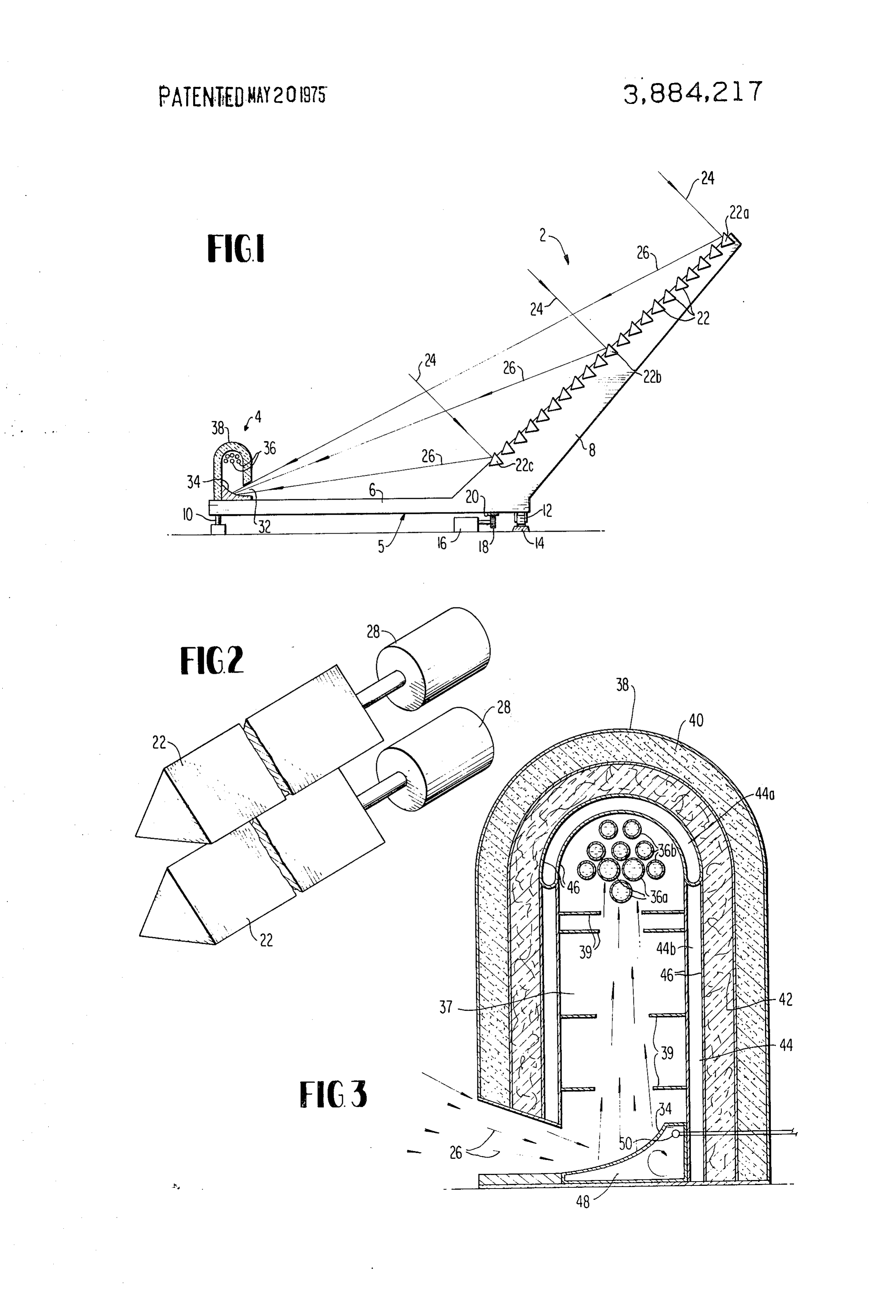
burning systems, such solar devices provide a non 5 FIG. 1 is a side elevation of a system constructed ac polluting source of usable energy. In many prior sys cording to the invention;
tems, one or more reflector units are mounted on a FIG. 2 is an enlarged fragmentary view of two of the framework which changes its inclination in dependence reflector units showing their preferred construction; upon the elevation of the sun, thereby assuring that the and, reflected solar energy will always be directed at the en FIG. 3 is an enlarged view of the energy receiving ergy receiving means. These previous systems impose means which includes a secondary reflector, a heat trap severe restrictions on the size of the reflector assembly and collector conduits for a heat exchange medium. since it must be capable of swinging movement in a ver The primary reflector assembly 2 and the energy re tical plane. ceiving means 4 are carried on a main fram 5 which has In some earlier systems, frames have carried a plural a horizontal portion 6 and an inclined portion 8, the lat ity of individually inclinable reflector units of parabolic ter of which carries the reflector assembly 2. The main cross-section, with each reflector unit having its own frame of the apparatus is constructed to swing in a hori energy receiving means located at the focus of the pa zontal arc about the vertical pivot pin 10 which estab rabola. These prior devices differ from the presently lishes the vertical axis of rotation for all individual units disclosed invention which has a single energy receiving 30 of the reflector assembly. A plurality of rollers, one of means which receives reflected solar energy from a plu which is shown at 12, are connected to the outer por rality of individually inclinable reflector units. tion of the frame 5 and ride on a arcuate trackway 14. This invention involves a number of interrelated con Preferably, control means are used to drive the frame cepts which are preferably but not essentially utilized 35 about the axis of the pin 10 so that the elongated hori together to provide a system of optimum capabilities. zontal axes of the individual reflector units will always According to one of the inventive concepts, a plurality lie approximately normal to the incident rays of the of spaced reflector units are oriented to produce con sun. This control means may act on the frame itself by verging beams of light, with means being provided for means of a stationary motor 16 which has its drive shaft changing the inclination of each reflector unit. This ar connected to a pinion 18 which meshes with an arcuate rangement lends itself for use in connection with con 40 rack gear 20 on the frame.
trol means for producing changes in the relative incli The reflector assembly 2 is formed of a large number nation between the individual reflector units so as to of individual reflector units 22 which are spaced apart vary the intensity of the reflected radiant energy strik to permit the passage of wind therebetween. The up ing the energy receiving means. permost of these reflector units is designated 22a, the The individual inclinability of the several reflector 45 medial unit is designated 22b and the lowermost reflec units permits their utilization with a control means for tor unit has been designated 22c.
producing equal angular movements of all units about Each of the reflector units is a horizontally elongated their respective horizontal axes of rotation during nor triangular prism, the central axis of which is immovable mal operation of the apparatus. This equal angular 50 with respect to the inclined portion 8 of the main frame movement is related to the apparent elevation of the 5. Rotation of all reflector units will usually be in equal sun to cause the reflected light to strike the means amounts, but for purposes which will be described which receives the reflected radiant energy. below it is desirable to provide control means which A further concept used in the disclosed apparatus in permits changes in the relative inclinication of the re volves a plurality of horizontally elongated reflector 55 flective surfaces of the different reflector units. units which are spaced from each other to permit the The parallel solar rays 24 strike the mirrored reflec passage of wind therebetween. This basic structure will tive faces of the reflector units, to be reflected as beams enable large installations to resist and withstand the 26 which focus as they approach the energy receiving forces imposed by high velocity winds. means 4. The reflected beam 26 from the uppermost Another concept suitable for use with the invention, 60 reflector unit 22a is, of course, at a greater inclination although not altogether new, pertains to a supporting from a horizontal plane than is the reflected ray 26 means which permits rotation of the elongated reflec from the lowermost reflector unit 22c. In order to tor units about a vertical axis which is related to the ap achieve this relationship, the reflective surface of the parent azimuth of the sun. This supporting means is op reflector 22a must be at a greater inclination from the erated by a control means to cause the rays of the Sun 65 horizontal plane than the reflective surface of the low to lie normal to a horizontal line on each reflector unit ermost reflector unit 22c. The inclination of the reflec to achieve maximum utilization of the Solar energy. In tive face of the medial unit 22b must lie between that connection with this, it is preferred that the horizontal of the reflector units 22a and 22c with all of the remain
Page 4
ing reflector units 22 also being slightly inclined with is reflected upwardly by the surface 34 and continues respect to each other. to converge until it strikes the energy absorbing con The utilization of many flat reflective surfaces which duits 36 which contain a circulating heat exchange me are spaced from each other is particularly desirable dium. These conduits 36 are located in the upper por since such an arrangement permits wind to pass tion of a chamber surrounded by inverted housing 38, through the reflector assembly. The importance of this which serves to trap the heat and prevent the conduc feature is particularly significant when the reflector as tive losses thereof.
sembly has an overall of thousands of square feet, Referring to FIG. 3, it will be seen that the walls of which would render it highly vulnerable to wind dam the inverted housing 38 are formed in three layers with age if it were a continuous surface. 10 the outer layer 40 being of a supercellular material, the One important reason for the prismatic shape of the middle layer 42 being made of asbestos fiber thermal individual reflector units is that it gives the unit a de insulation and the innermost layer 44 being a hollow gree of structural rigidity which is unavailabile in flat capsule with an upper portion 44a which is evacuated mirrors, so that the reflector units do not bow exces to minimize the transmission of heat therethrough, and sively due to their own weight or when subjected to 15 a lower section 44b through which a gaseous heat trans high velocity winds. fer medium is circulated to remove heat for use in Another desirable feature of the prismatic structure space heating or utilization in low heat conversion of the reflector units is that it provides multiple sur units.
faces. If desired, the respective surfaces may be pro Within the chamber 37, there are interiorly vided with a mirror finish for use on cloudy days, a pol extending baffles 38 which have light-reflecting upper ished aluminum finish for use on sunny days and a surfaces and light-absorbing lower surfaces coated with scour-resistant face which may be a light-colored rub carbon black or other material which will promote its ber or plastic for exposure to the elements in the event absorption of radiant solar energy. of sandstorms which would be injurious to the silvered As previously explained, the convergent beams of or polished reflective surfaces. If more than one of the 25 light from the reflector assembly enter the energy re surfaces of the reflector unit is reflective, it is possible ceiving means 4 through the elongated opening 32. The to have one such surface in use while the other surface solar energy then strikes the reflective surface 34 of an is being polished or cleaned preparatory to its service. elongated hollow body filled with a heat transfer liquid As illustrated in FIG. 2, the individual reflector units 48 which is circulated therethrough under the influ may be operated by stepping motors 28. These stepping ence of a pump or other circulating means. A tempera motors may receive actuating pulses from a storage or ture sensing device 50 such as a thermocouple may be memory device which utilizes punched paper tape or a used to control the rate of circulation of the liquid heat magnetic recording medium which is programmed ac exchange medium 48 and to change the intensity of cording to the known astronomical position of the sun 35 Solar energy arriving at the reflective surface 34 in case in order to position the reflector surface properly. Sev of dangerous overheat.
eral adjacent reflector units may be operated by a com The principal energy absorbing means is the heat ex mon stepping motor since there is little angular differ change fluid contained in the conduits 36a, each of ence between adjacent reflector units. which is made of stainless steel and covered with car One advantage of having individual control of the re 40 bon black pigment particles. These tubes carry a super flector units is that it permits control of the intensity of heated heat eXchange liquid to a storage cavern or to the reflected light arriving at the energy receiving a heat exchanger where the thermal energy may be uti means 4. The amount of convergence of the reflected lized or converted to other forms of energy suitable for beams 26 may be varied so that the energy may be con future use. The nest of preheat transfer tubes 36b also centrated either in a very small area or a very large area 45 carry a circulating liquid heat exchange medium. These as it arrives at the energy collecting means 4. This in tubes are copper and are covered with carbon black to tensity control also may be used as a safety feature in promote their absorption of the solar energy. If desired, the event of malfunction of the apparatus or the entry the tubes 36b may be arranged for series flow or they of birds or foreign objects in the high temperature zone may be arranged in parallel with a common header at in the vicinity of the energy receiving means 4. In such 50 the opposite ends of the nest of tubes 36b. The liquid instances, the reflector units may be rotated so that preheated by the tubes 36b may then be fed through their reflective surfaces are mutually parallel so that the tubes 36a if desired where the heat exchange me there may be no convergence of the reflected beams dium is heated to its maximum temperature. and no concentration of the solar energy by the appara Those skilled in the art will realize that extremely tuS. high temperature will exist within the heat receiving The intensity of the energy arriving at the energy re 55 means 4 and that it may become necessary to utilize ceiving means 4 may also be affected by rotating only materials other than those listed above to provide suffi some of the reflector units 22, for example by making cient safety factors for actual commercial operation. their reflective surfaces normal to the sun so that the The liquid heat exchange medium may be the same as reflected solar energy will not be directed at the energy 60 is used in shipboard or land-based nuclear reactor receiving means 4. units. Liquid sodium, lead, mercury or various salts The energy receiving means 4 is an elongated assem may be used.
bly which corresponds in length to the individual re The typical operation of the preferred embodiment flector units 22. The light reflected by the reflector of the invention will now be described. The parallel units 22 will form a highly concentrated beam which 65 rays of the sun will strike the reflective surfaces of the enters the energy receiving unit 4 through an elongated adjustable reflector units 22 which are oriented to pro opening 32 and then strikes the reflective surface 34 duce a convergence of the reflected light in an elon which may be either flat or parabolic. The solar energy gated area located at the energy receiving means 4. The
Page 5
S 6 reflector units 22 are individually rotated about their plurality of reflector units each of which includes a re horizontal axes, either singly or in groups, to produce flector body with a flat horizontally elongated reflec the continued convergence of the beams of light at the tive surface which is rotatable about a vertically im energy receiving means 4 throughout the changes of movable substantially horizontal axis of rotation which the elevation angle of the sun. These changes in inclina 5 is spaced from the horizontal axes of rotation of other tion of the reflective surfaces are produced by the step said reflector units, and means for rotatably positioning ping motors or other devices which have been pro said reflector bodies about their respective axes of rota grammed according to the predetermined elevation tion to produce a convergence of radiant solar energy angle of the sun. reflected therefrom along the length of the horizontally As the azimuth of the sun changes, a memory device 10 elongated energy receiving means, said reflector bodies sends pulses to the motor 16, thereby rotating the gear being geometrical prismatic elements with the reflec 18 which drives the rack 20 and the frame 5 in a swing tive surfaces thereof constituting one face of the pris ing movement about the vertical pivot 10. This move matic structure, said prismatic elements having three ment is programmed so that the horizontal axes of the faces of substantially similar dimensions. reflector units 22 will also remain normal to the inci 15 2. The apparatus of claim 1 wherein the reflector dent rays 24 of the sun, following in the northern hemi units are spaced apart to permit the passage of air sphere the movement of the sun from an easterly direc therebetween whereby said apparatus is resistant to tion to the south and finally to the west. In the southern wind-created forces.
hemisphere, the sun's azimuth will change from an 3. The apparatus of claim 1 having means for rotating easterly direction to the north and finally to the south. 20 the reflector bodies and the horizontally elongated en At a time after sunset and before sunrise, the apparatus ergy receiving means about a vertical axis related to the is returned to a position where the axes of the reflec azimuth of the sun to cause the rays of the sun to lie tions 22 will lie perpendicular to the sun at the forth normal to the horizontal axes of the respective reflector coming sunrise. units.
At all times during the normal operation of the appa 4. The apparatus of claim 3, wherein the horizontal ratus, the rays of light 26 reflected by the reflector units axes of the reflector bodies are horizontally immovable 22 will converge in the area of the energy receiving with respect to each other and all reflector bodies are means 4. However, when the temperature in this area horizontally rotatable about a single vertical axis. becomes too high or when foreign objects approach the 5. Apparatus according to claim 1 wherein the means high temperature area of the apparatus, some or all of 30 for rotatably positioning said reflector bodies about the reflector units 22 may be rotated about their hori their respective horizontal axes during normal opera zontal axes to reduce the concentration of solar energy tion of the apparatus produces equal angular move in the vicinity of the energy receiving means 4. This ments of all reflector bodies about their respective hor may be done by reducing the degree of convergence of izontal axes, said equal angular movements being re the reflected beams 26 or by redirecting only certain 35 lated to the elevation of the sun to cause the radiant ones of the reflector units 22 so that their reflected solar energy reflected thereby to strike the energy re light is no longer directed toward the energy receiving ceiving means.
means 4. 6. The apparatus of claim 5 having means for reduc On extremely large installations, the rotation of the 40 ing the concentration of solar energy at the energy re entire assembly about a pin 10 may not be practical, in ceiving means by rotating the reflector bodies to re which case the energy receiving means 4 may alone be duce the degree of convergence of the reflected beams. movable longitudinally in a direction parallel to the 7. The apparatus of claim 6 having means for reduc horizontal axes of the reflector units 22; or, the entire ing the concentration of solar energy at the energy re energy receiving means 4 may be constructed so as to ceiving means by rotating only some of the reflector be stationary but considerably longer than the reflector 45 bodies so that their reflected light is no longer directed units 22 so that the light reflected by the units 22 will toward the energy receiving means. always strike some portion of the energy receiving 8. Apparatus for collecting and receiving solar en means 4. Of course, there are many other approaches ergy, comprising, means for receiving high intensity ra which may be used to ensure that the reflected energy 50 diant solar energy, a primary reflector unit for directing will strike the energy receiving means 4. converging beams of solar energy on the energy receiv It will be evident that many different types of energy ing means, said energy receiving means comprising a receiving means may be used other than the preferred housing of stationary inclination having an interior embodiment which is shown herein. For example, ap chamber and means at its lower portion for admitting paratus may be used for performing high temperature the high, intensity radiant solar energy to the interior experiments on metallurgical specimens placed at the 55 chamber, said housing having walls of thermally insu area of convergence of the reflected beams. In view of lating material, and conduit means for a circulating the prospect of many other modifications within the heat exchange fluid located in an upper portion of the spirit of the invention, it should be remembered that interior chamber in the path of the high intensity radi this invention is not limited only to the disclosed em 60 ant Solar energy, and an upwardly facing concave sec bodiment but encompasses other methods and appara ondary reflector means in the housing and located in tus within the spirit of the claims which follow: the path of high intensity radiant solar energy admitted I claim: to the interior chamber, said secondary reflector means 1. Apparatus for collecting radiant solar energy com being horizontally elongated and said secondary reflec prising a horizontally elongated energy receiving 65 tor means being oriented to reflect the high intensity means, a reflector assembly located in the path of radi radiant Solar energy upwardly onto said conduit means. ant solar energy for reflecting said energy upon the en 9. The energy receiving means of claim 8 having baf ergy receiving means, said reflector assembly having a fle means located in said interior chamber, said baffle
Page 6
means having a reflective surface facing the conduit flector means being oriented to reflect the high inten means and a non-reflective surface facing the secon sity radiant solar energy upwardly onto said conduit dary reflector means. means, and baffle means located in said interior cham 10. The energy receiving means of claim 9 wherein ber, said baffle means having a reflective surface facing the interior wall of the housing is reflective and the ex the conduit means and a non-reflective surface facing terior surface of the conduit means is nonreflective. the secondary reflector means. 11. An energy receiving means for receiving high in 12. A method of collecting and receiving solar en tensity radiant solar energy directed thereupon by a re flector unit, said energy receiving means comprising a ergy, ergy comprising the steps of, concentrating Solar en by reflecting and directing converging beams housing of stationary inclination having an interior 10 thereof downwardly into the lower portion of a cham chamber and means at its lower portion for admitting the high intensity radiant solar energy to the interior ber formed of thermally insulating material, reflecting chamber, said housing having walls of thermally insu the concentrated solar energy upwardly by a concave lating material, and conduit means for a circulating horizontally-elongated secondary reflector located in heat exchange fluid located in an upper portion of the 5 the chamber and receiving the concentrated solar en interior chamber in the path of the high intensity radi ergy at a conduit located in an upper portion of the ant solar energy, an upwardly facing secondary reflec chamber, and passing a heat exchange fluid through the tor means located in the path of high intensity radiant conduit and then awayck fromk the
chamber.
solar energy admitted to the interior chamber, said re

Provenance
- Collection
- Cited prior art
- Original PDF
- patentimages.storage.googleapis.com →
- Filed
- 1972-09-20
- Pages
- 6
- Method
- pdftotext (the PDF's own text layer) + pdftoppm 300dpi page scans
- Source
- Google Patents bibliographic record
- Granted
- 1975-05-20
- Inventors
- Lloyd Lore Wartes; ECOTHERMIA Inc
- Transcribed from
- patentimages.storage.googleapis.com →