patent · US3861379
Low profile solar ray concentrator
21 January 1975
Page 1 — bibliographic record
United States Patent (19) 11) 3,861,379 Anderson, Jr. (45) Jan. 21, 1975
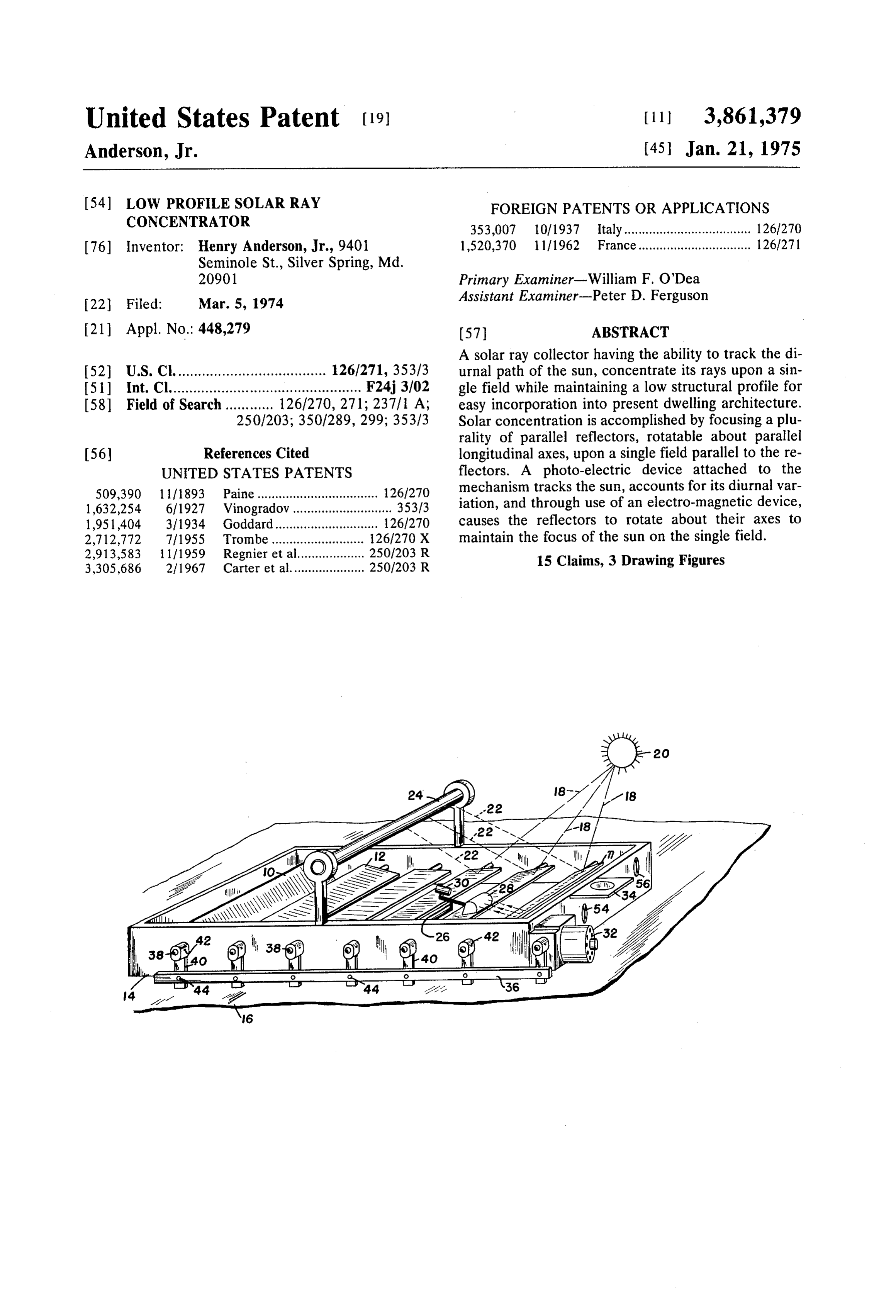
54) LOW PROFILE SOLAR RAY FOREIGN PATENTS OR APPLICATIONS CONCENTRATOR 353,007 10/1937 Italy.................................... 126/270 76) Inventor: Henry Anderson, Jr., 9401 1,520,370 1 1/1962 France................................ 1261271 Seminole St., Silver Spring, Md.
20901 Primary Examiner-William F. O'Dea 22 Filed: Mar. 5, 1974 Assistant Examiner-Peter D. Ferguson (21) Appl. No.: 448,279 (57) ABSTRACT A solar ray collector having the ability to track the di 52 U.S. C. ..................................... 126/271, 353/3 urnal path of the sun, concentrate its rays upon a sin 5ll Int. Cl................................................ F24j.3/02 gle field while maintaining a low structural profile for 58 Field of Search............ 126/270, 271; 237/1 A; easy incorporation into present dwelling architecture. 2501203; 350/289, 299; 353/3 Solar concentration is accomplished by focusing a plu rality of parallel reflectors, rotatable about parallel (56) References Cited longitudinal axes, upon a single field parallel to the re UNITED STATES PATENTS flectors. A photo-electric device attached to the 509,390 1 1/1893 Paine.................................. 1261270 mechanism tracks the sun, accounts for its diurnal var 1,632,254 6/1927 Vinogradov............................ 353/3 iation, and through use of an electro-magnetic device, 1951,404 3/1934 Goddard............................. 126/270 causes the reflectors to rotate about their axes to 2,712,772 7/1955 Trombe............... ... 126/270 X maintain the focus of the sun on the single field. 2,913,583 1 1/1959 Regnier et al.... ... 2501203 R 15 Claims, 3 Drawing Figures 3,305,686 2/1967 Carter et al..................... 2501203 R
Page 2
Drawing sheet — no readable text.
Page 3
LOW PROFILE SOLAR RAY CONCENTRATOR efficient focusing of N by M universally adjustable re BACKGROUND OF THE INVENTION flectors would be difficult to achieve, resulting in ineffi cient heat transfer.
This invention relates to a solar energy concentrator, SUMMARY OF THE INVENTION and more particularly to a system for tracking the sun and converting the solar energy for heating purposes. Accordingly, there is provided a solar concentrator Solar energy collectors are designed to trap the radi comprising reflecting surfaces coupled together such ant energy of the sun, which is a form of heat, and raise that all reflecting surfaces rotate about their longitudi the temperature of an intermediary fluid, normally wa nal axes through the same angle. The concentrator. ter. This hot water can then be used to heat dwellings O comprising an array of reflecting surfaces, mounted on or for other purposes. For home use, a collector would a framework firmly attached to a structure, tracks the need approximately 1,000 square feet of collective sun by rotating only the individual reflecting surfaces aea. through the same angle and maintains the focus of the Collector designs which do not concentrate the sun's sun upon a boiler tube. Tracking of the sun is accom rays are most commonly seen in home use. Because no 5 plished by employing a photo-electric device coupled concentration of the sun's rays occurs, the diurnal path to an electromagnetic device which rotates the reflect of the sun need not be accounted for; i.e., no tracking ing surfaces.
is necessary, and the collector can remain firmly af OBJECTS OF THE INVENTION fixed to the dwelling. Although the resultant tempera ture rise of the intermediary fluid is low (about 100°F) 20 It is therefore an object of the present invention to and large heat storage volumes are required to provide provide an improved solar ray concentrator. heat during sunless hours, the designs themselves are Another object of the present invention is to provide easily adapted architecturally to existing home con a solar tracker to provide economical home heating ca struction techniques. - pabilities.
Collectors which concentrate the sun's rays are usu 25 Yet another object of the present invention is to pro ally reflectors of the Fresnel or parabolic type. All con vide a solar ray tracker and concentrator which main centrating reflectors focus the rays of the sun on a sin tains a low, fixed structure profile to be aesthetically gle field. This requires that the focal line of the collec pleasing to incorporate into existing home architecture. tor always point at the sun; i.e., that sun tracking is re Still another object of the present invention is to pro quired. Since very high temperatures are obtainable 30 vide a solar ray concentrator of relatively low cost and with these devices, the heat storage volume, which is size to produce an economical source of power. inversely proportional to the collector temperature, A further object of the present invention is to provide would be significantly smaller if adapted to home use. a pre-focused sun tracking device which may track the Steam production at the collector would also become S.
feasible, leading to further utilization of the radiant en 35 BRIEF DESCRIPTION OF THE DRAWINGS ergy of the sun.
A major drawback arises when adapting the concen These and other objects, features and attendant ad trating collector to home usage. Since this collector vantages of the present invention will become better must also have 1,000 square feet of collective area, the understood by reference to the following detailed de feat of moving such a large collector while tracking the 40 scription when considered in connection with the ac sum would be economically unfeasible to incorporate companying drawings wherein:
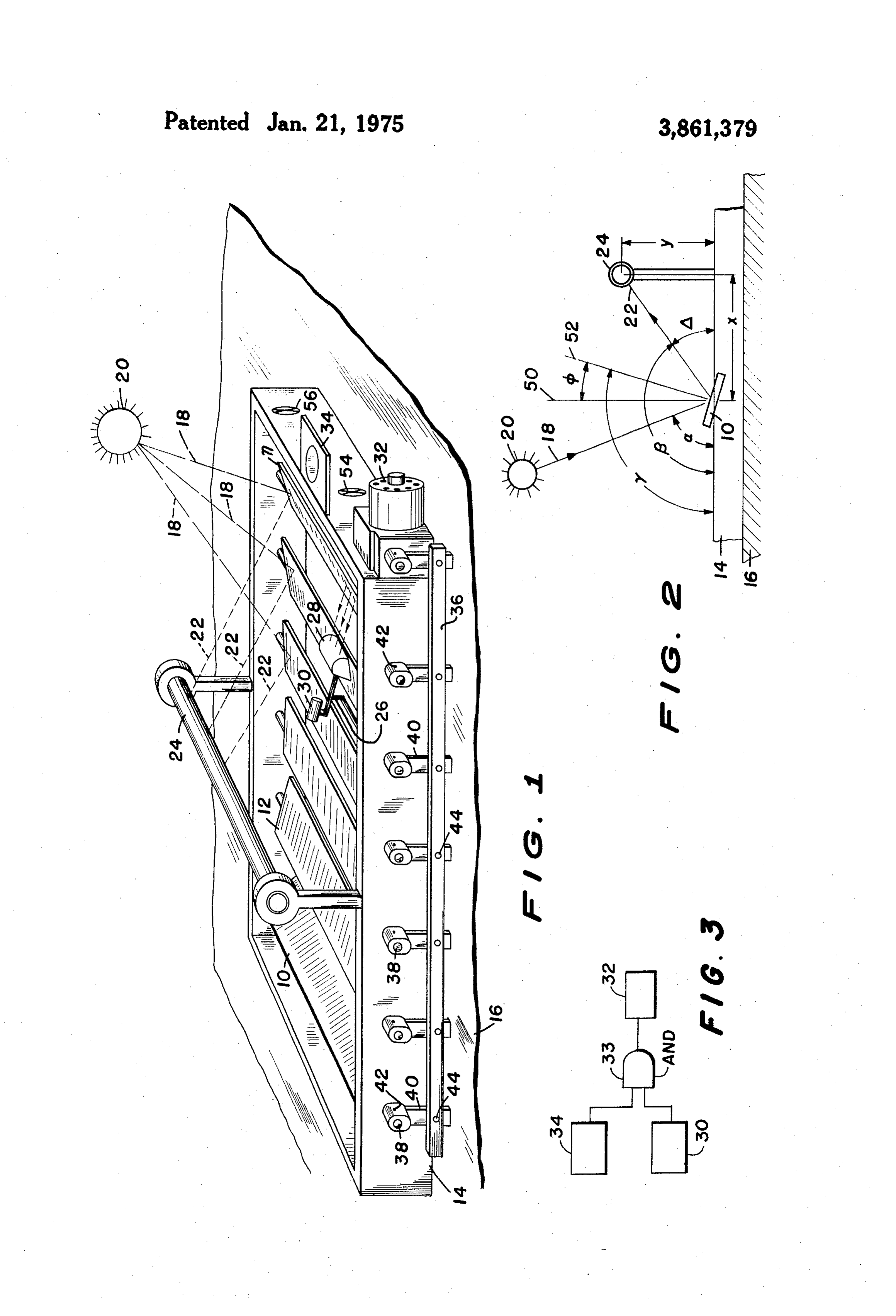
in home usage. Thus, the advantages of high collector FIG. 1 is an isometric view of the solar ray concentra temperatures have not been feasible until now. tor according to this invention; The use of an array of mirrors to focus the rays of the 45 FIG. 2 is a schematic diagram depicting the angles sun upon a single field is disclosed in U.S. Pat. No. between the various elements of the solar concentrator 260,657, and 412,724, in which the array of N rows by according to this invention; and
M columns of reflectors track the sun by moving (by a FIG. 3 is a schematic diagram illustrating a system for clock-work mechanism) the entire array about a fixed coupling the two photoelectric devices to the electro point upon which the sun's rays are concentrated by 50 magnetic device according to this invention. using a lens. Columns and rows of fixed reflectors to DESCRIPTION OF THE PREFERRED concentrate the suns rays upon a single point are again EMBODIMENT
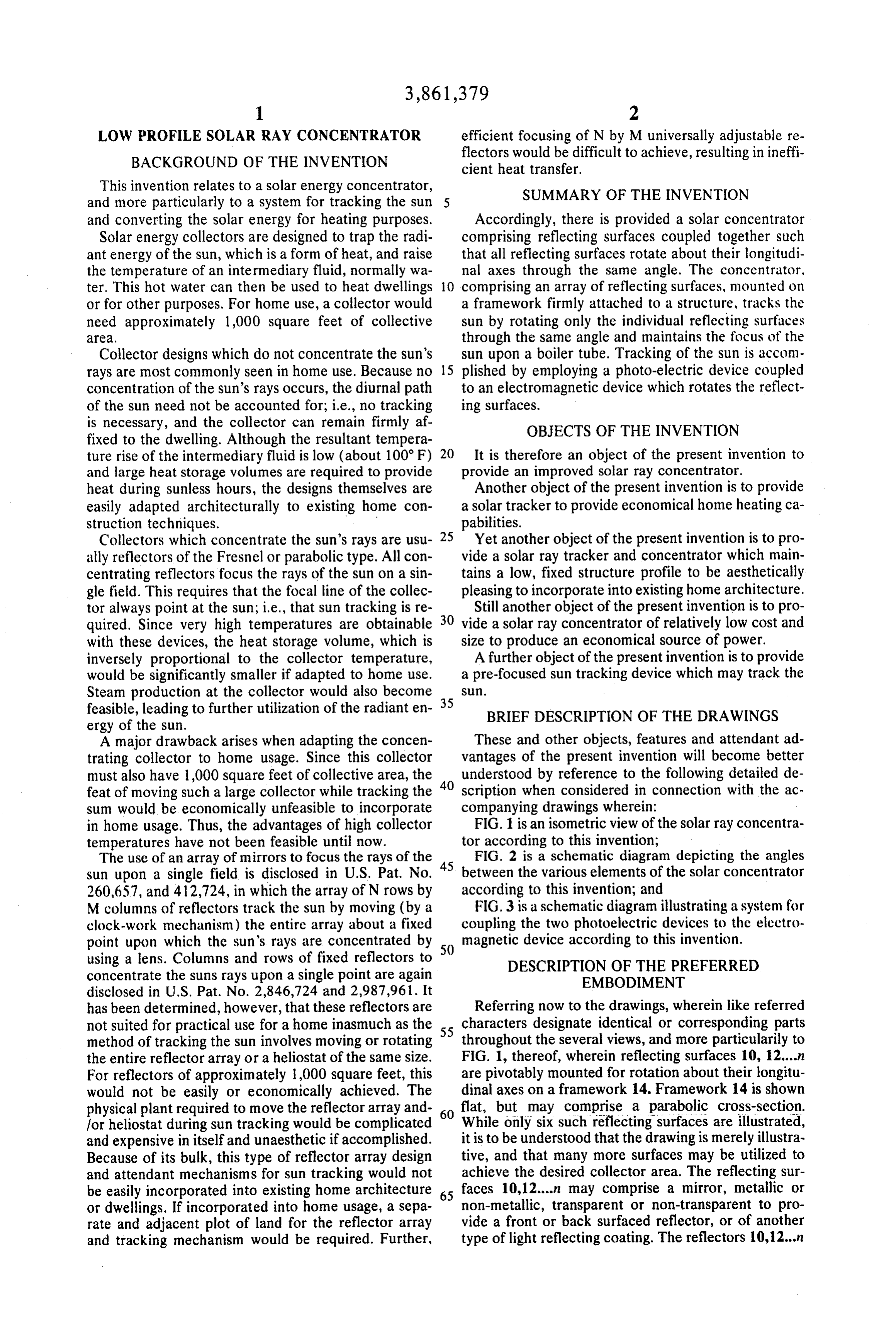
has been determined, however, that these reflectors are Referring now to the drawings, wherein like referred not suited for practical use for a home inasmuch as the 55 characters designate identical or corresponding parts method of tracking the sun involves moving or rotating throughout the several views, and more particularily to the entire reflector array or a heliostat of the same size. FIG. 1, thereof, wherein reflecting surfaces 10, 12....n For reflectors of approximately 1,000 square feet, this are pivotably mounted for rotation about their longitu would not be easily or economically achieved. The dinal axes on a framework 14. Framework 14 is shown physical plant required to move the reflector array and 60 flat, but may comprise a parabolic cross-section. for heliostat during sun tracking would be complicated While only six such reflecting surfaces are illustrated, and expensive in itself and unaesthetic if accomplished. it is to be understood that the drawing is merely illustra Because of its bulk, this type of reflector array design tive, and that many more surfaces may be utilized to and attendant mechanisms for sun tracking would not achieve the desired collector area. The reflecting sur be easily incorporated into existing home architecture 65 faces 10,12....n may comprise a mirror, metallic or or dwellings. If incorporated into home usage, a sepa non-metallic, transparent or non-transparent to pro rate and adjacent plot of land for the reflector array vide a front or back surfaced reflector, or of another and tracking mechanism would be required. Further, type of light reflecting coating. The reflectors 10,12...n
Page 4
are shown as rectangularly shaped, although any other is coupled to collar and lever assembly 40 by a set suitable configuration, such as parabolic or circular screw 42 or similar functioning attachment or clamping cross section to achieve solar concentration may be arrangement. Assembly 40 is also pinned to alignment employed. Framework 14 is fixably mounted on struc bar 36 by element 44 to allow free rotation. Similarly, ture 16, such as a dwelling roof or the like, and is tilted reflectors 12....in are coupled to alignment bar 36, and to insure that the plane of the framework is perpendic thereby to each other, in an identical manner. The dis ular to the declination plane of the sun. Perpendicu tance between shafts 38 and the elements 44 pinning larity would not be necessary to track sun 20, but it assemblies 40 to alignment bar 36, are equal, such that would be an optimum setting for the collector 24, when bar 36 is caused to move by electro-magnetic de which may comprise a boiler tube, at a specific time of 10 vice 32, to which it is connected, all reflectors 10, 12...in the year because of the perpendicularity of the sun's rotate through the same angle for reasons to be de incident rays upon the reflectors 10,12....n. At other scribed hereinafter. The levers and bars can be re times of the year, the efficiency of the collector would placed by gears, chains or sprockets to achieve the be slightly reduced. In areas distance from the equator, same effect.
retilting the framework twice a year would improve the 5 The advent of a partly cloudy day could disrupt the overall efficiency of the collector 24. tracking of the sun 20. To eliminate this potentiality, a In operation, each of the reflecting surfaces second photo-electric device 34, mounted to frame 10, 12....n are pre-focused during assembly to frame work 14, is employed. If it were shaded, due to a cloudy work 14 onto a boiler tube 24 according to equation day, it would interrupt a rotation signal from photo (1) to be described hereinafter, wherein incident solar 20 electric device 30 to electromagnetic device 32, and rays 18 from the sun 20 are reflected from the reflect prevent rotation of the reflectors 10,12...n. Referring ing surfaces 10,12....n as reflected rays 22 to be inter to FIG. 3, a simple AND GATE 33 having as its inputs cepted by the boiler tube 24 (collector). Boiler tube 24 the outputs of photo-electric devices 30 and 34, and is shown as a single tube and as long as reflecting sur having its output coupled electrically to the electro faces 10, 12....n, but can also have a non-circular cross 25 magnetic device 32 could accomplish this operation al section, or may comprise an arrangement of more than though any other similar arrangemennt may be em one tube, and further may comprise of a metallic or ployed. When photo-electric device 34 is re non-metallic material. Insulation on the non-irradiated area or a secondary reflector to trap rays reflected from 30 illuminated by the incident rays 18 from the sun 20, photo-electrical device 30 would be allowed to com the boiler tube 24 can also be included. A medium, plete its aforementioned task.
such as liquid or vapor flowing through boiler tube 24 The preceding discussion applies to a situation when is heated by reflected rays 22 and can be utilized for the sun's position leads that of the position of the sun heating purposes or other practical uses. detector 26, and occurs when the normal tracking of A sun detector 26 is shown attached to the frame the sun is interrupted by clouds. In the morning, at the work 14 comprising cylindrical lens 28 and a photo beginning 35 electric device 30 situated in the focal line of the lens. of the tracking day, a reverse situation oc The focal line of detector 26, since it uses a cylindrical the position ofthe curs in which the position of the sun could lag that of sun detector 26. To eliminate pre lens 28, lies in the reflective plane comprising the cen mature and erroneous tracking of the sun 20, the physi terlines of the boiler tube 24 and an arbitrary reflector 40 cal geometry of photo-electric device 34 is such that it n, both of which are parallel to each other, and is ad cannot be illuminated by the morning justed such that when reflector n is properly focused on is possible, by the limit of the angle ofsun 20 before it the boiler tube 24, photo-electric device 30 in the de flecting surface n, for the sun 20 to illuminateof therotation re tector 26 is illuminated by the reflected rays 22 from the sun 20. Movement of the sun 20 during the day re 45 photo-electric device 30 of sun detector 26. sults in the movement of reflected rays 22 whereby toAthetimer or a limit switch 54, which may be mounted framework 14 and activated at the end of the photo-electric device 30 becomes un-illuminated, or day, causes shaded. When shaded, it causes an electromagnetic de 10,12.....n to the the motor 32 to return the reflectors morning position.
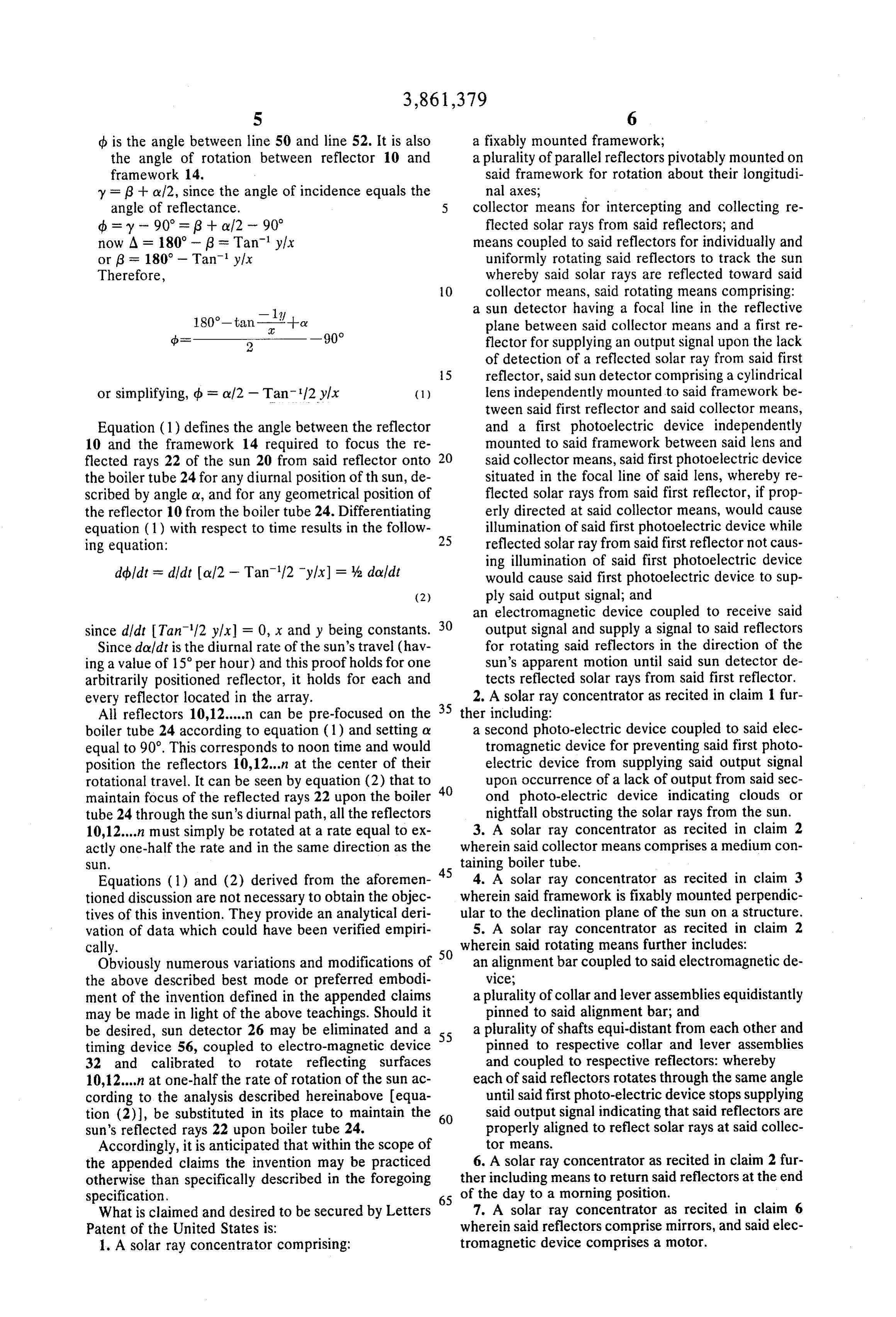
vice 32, to which it is electrically connected, to uni formly rotate, through a system of gears and levers, to 50 Referring now to FIG. 2, there is shown the relation be described hereinafter, all the reflective surfaces ship between the various elements in the solar concen 10, 12....n, including reflector n, in such a direction that trator according to this invention for pre-focusing re the photo-electric device 30 is once again illuminated. flectors 10,12....n during assembly to framework 14 whereby the rays reflected from the reflectors would
When this occurs, the rotation of the reflectors 10, 12....n, is stopped by electrically stopping the elec 55 strike the boiler tube 24. Derived also is analytical veri tromagnetic device, and the sun's rays reflected from fication of the idea of coupled reflectors which rotate reflector n are once again properly focused on boiler uniformly together to track the sun and their rate of ro tube 24. Since all reflecting surfaces 10,12....n are pre tation.
focused on the boiler tube 24 during assembly, when Boiler tube 24 is located a distance along the hori reflector n is focused on boiler tube 24, all reflective 60 zontal x and a vertical distancey from the reflector 10. surfaces 10, 12....,n are properly focused on boiler tube to Line 50 is normal to the framework 14 and 52 is normal 24. In this manner, the sun 20 is tracked in its diurnal the reflector 10.
path while maintaining proper focus of its rays re y is the angle between framework 14 and line 52, flected from reflective surfaces 10,12....n upon the 6 is the angle between framework 14 and the re boiler tube 24. 65 flected ray 22,
Reflectors 10,12....n are coupled to one another and a is the angle between framework 14 and the incident the electromagnetic device 32 through alignment bar ray 18, 36. Pivot shaft 38 is firmly attached to reflector 10 and A is the supplement angle of angle (3,
Page 5
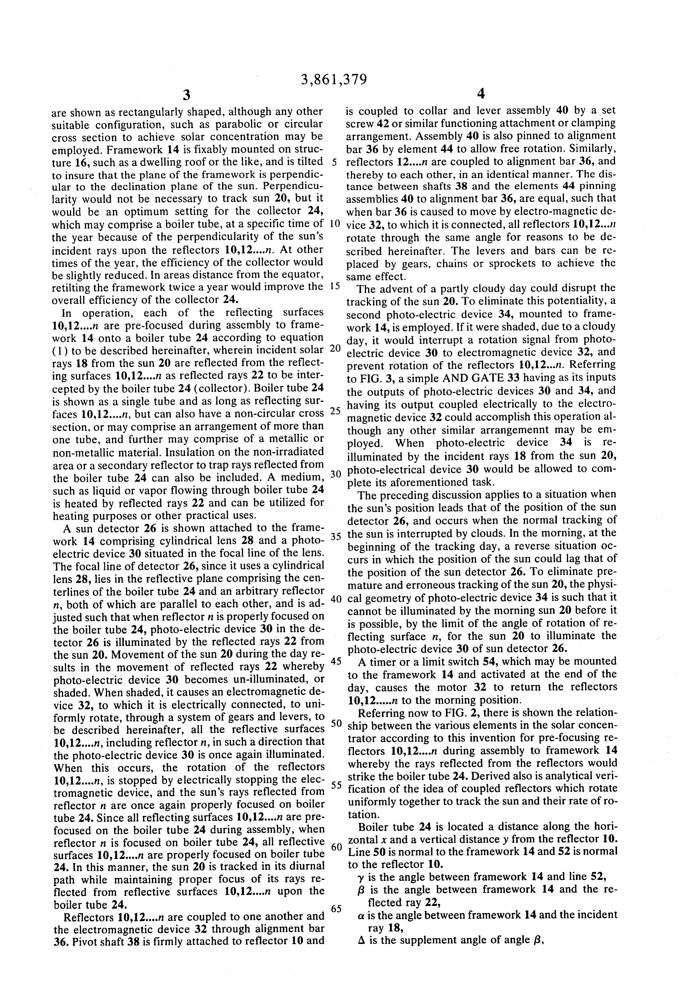
S 6 d is the angle between line 50 and line 52. It is also a fixably mounted framework; the angle of rotation between reflector 10 and a plurality of parallel reflectors pivotably mounted on framework 14. said framework for rotation about their longitudi y = 3 + c 12, since the angle of incidence equals the nal axes;
angle of reflectance. 5 collector means for intercepting and collecting re d = y - 90° = 3 + af2 - 90° flected solar rays from said reflectors; and now A = 180°- 3 = Tani y/x means coupled to said reflectors for individually and or 6 = 180° - Tani y/x uniformly rotating said reflectors to track the sun Therefore, whereby said solar rays are reflected toward said O collector means, said rotating means comprising:
a sun detector having a focal line in the reflective plane between said collector means and a first re flector for supplying an output signal upon the lack of detection of a reflected solar ray from said first 15 reflector, said sun detector comprising a cylindrical or simplifying, db = c/2 - Tan 12 y/x (1) lens independently mounted to said framework be tween said first reflector and said collector means,
Equation (1) defines the angle between the reflector and a first photoelectric device independently 10 and the framework 14 required to focus the re mounted to said framework between said lens and flected rays 22 of the sun 20 from said reflector onto 20 said collector means, said first photoelectric device the boiler tube 24 for any diurnal position of th sun, de situated in the focal line of said lens, whereby re scribed by angle o, and for any geometrical position of flected solar rays from said first reflector, if prop the reflector 10 from the boiler tube 24. Differentiating erly directed at said collector means, would cause equation (1) with respect to time results in the follow illumination of said first photoelectric device while ing equation: 25 reflected solar ray from said first reflector not caus ing illumination of said first photoelectric device debildt = d/dt of2 - Tan/2 y/x) = % doldt would cause said first photoelectric device to sup (2) ply said output signal; and an electromagnetic device coupled to receive said since didt Tan'/2 y/x) = 0, x and y being constants. 30 output signal and supply a signal to said reflectors Since doldt is the diurnal rate of the sun's travel (hav for rotating said reflectors in the direction of the ing a value of 15' per hour) and this proof holds for one sun's apparent motion until said sun detector de arbitrarily positioned reflector, it holds for each and tects reflected solar rays from said first reflector. every reflector located in the array. 2. A solar ray concentrator as recited in claim 1 fur All reflectors 10,12.....n can be pre-focused on the 35 ther including:
boiler tube 24 according to equation (1) and setting or a second photo-electric device coupled to said elec equal to 90°. This corresponds to noon time and would tromagnetic device for preventing said first photo position the reflectors 10,12...in at the center of their electric device from supplying said output signal rotational travel. It can be seen by equation (2) that to upon occurrence of a lack of output from said sec maintain focus of the reflected rays 22 upon the boiler 40 ond photo-electric device indicating clouds or tube 24 through the sun's diurnal path, all the reflectors nightfall obstructing the solar rays from the sun. 10, 12....n must simply be rotated at a rate equal to ex 3. A solar ray concentrator as recited in claim 2 actly one-half the rate and in the same direction as the wherein said collector means comprises a medium con SU. taining boiler tube.
Equations (1) and (2) derived from the aforemen 45 4. A solar ray concentrator as recited in claim 3 tioned discussion are not necessary to obtain the objec wherein said framework is fixably mounted perpendic tives of this invention. They provide an analytical deri ular to the declination plane of the sun on a structure. vation of data which could have been verified empiri 5. A solar ray concentrator as recited in claim 2 cally. wherein said rotating means further includes: Obviously numerous variations and modifications of 50 an alignment bar coupled to said electromagnetic de the above described best mode or preferred embodi vice;
ment of the invention defined in the appended claims a plurality of collar and lever assemblies equidistantly may be made in light of the above teachings. Should it pinned to said alignment bar; and be desired, sun detector 26 may be eliminated and a 55 a plurality of shafts equi-distant from each other and timing device 56, coupled to electro-magnetic device pinned to respective collar and lever assemblies 32 and calibrated to rotate reflecting surfaces and coupled to respective reflectors: whereby 10, 12...,n at one-half the rate of rotation of the sun ac each of said reflectors rotates through the same angle cording to the analysis described hereinabove equa until said first photo-electric device stops supplying tion (2)), be substituted in its place to maintain the 60 said output signal indicating that said reflectors are sun's reflected rays 22 upon boiler tube 24. properly aligned to reflect solar rays at said collec Accordingly, it is anticipated that within the scope of to meanS.
the appended claims the invention may be practiced 6. A solar ray concentrator as recited in claim 2 fur otherwise than specifically described in the foregoing ther including means to return said reflectors at the end specification. 65 of the day to a morning position. What is claimed and desired to be secured by Letters 7. A solar ray concentrator as recited in claim 6 Patent of the United States is: wherein said reflectors comprise mirrors, and said elec 1. A solar ray concentrator comprising: tromagnetic device comprises a motor.
Page 6
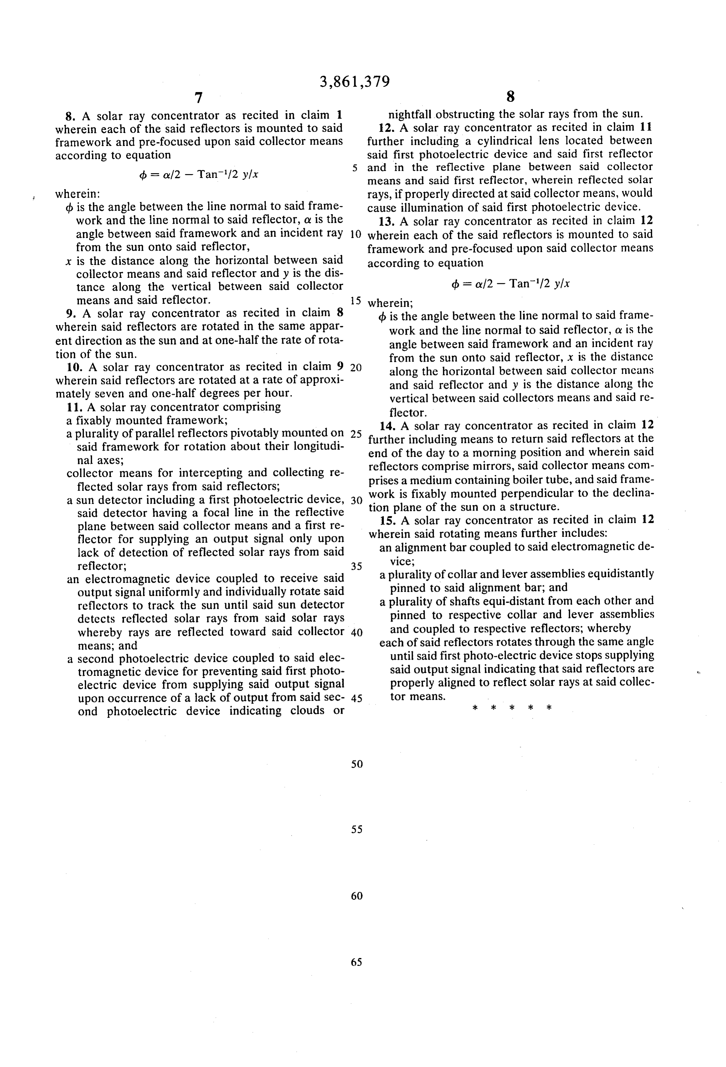
8. A solar ray concentrator as recited in claim 1 nightfall obstructing the solar rays from the sun. wherein each of the said reflectors is mounted to said 12. A solar ray concentrator as recited in claim 11 framework and pre-focused upon said collector means further including a cylindrical lens located between according to equation said first photoelectric device and said first reflector d = ov/2 - Tan/2 y/x and in the reflective plane between said collector means and said first reflector, wherein reflected solar wherein: rays, if properly directed at said collector means, would d is the angle between the line normal to said frame cause illumination of said first photoelectric device. work and the line normal to said reflector, or is the 13. A solar ray concentrator as recited in claim 12 angle between said framework and an incident ray 10 wherein each of the said reflectors is mounted to said from the sun onto said reflector, framework and pre-focused upon said collector means x is the distance along the horizontal between said according to equation collector means and said reflector and y is the dis tance along the vertical between said collector d = ov/2 - Tan/2 y/x means and said reflector. 15 wherein;
9. A solar ray concentrator as recited in claim 8 d is the angle between the line normal to said frame wherein said reflectors are rotated in the same appar work and the line normal to said reflector, or is the ent direction as the sun and at one-half the rate of rota angle between said framework and an incident ray tion of the sun. from the sun onto said reflector, x is the distance 10. A solar ray concentrator as recited in claim 9 20 along the horizontal between said collector means wherein said reflectors are rotated at a rate of approxi and said reflector and y is the distance along the mately seven and one-half degrees per hour. vertical between said collectors means and said re 11. A solar ray concentrator comprising flector.
a fixably mounted framework; 14. A solar ray concentrator as recited in claim 12 a plurality of parallel reflectors pivotably mounted on 25 further including means to return said reflectors at the said framework for rotation about their longitudi end of the day to a morning position and wherein said nal axes; reflectors comprise mirrors, said collector means com collector means for intercepting and collecting re prises a medium containing boiler tube, and said frame flected solar rays from said reflectors; work is fixably mounted perpendicular to the declina a sun detector including a first photoelectric device, 30 tion plane of the sun on a structure. said detector having a focal line in the reflective 15. A solar ray concentrator as recited in claim 12 plane between said collector means and a first re wherein said rotating means further includes: flector for supplying an output signal only upon an alignment bar coupled to said electromagnetic de lack of detection of reflected solar rays from said vice;
an electromagnetic device coupled to receive said a plurality of collar and lever assemblies equidistantly output signal uniformly and individually rotate said pinned to said alignment bar; and reflectors to track the sun until said sun detector a plurality of shafts equi-distant from each other and detects reflected solar rays from said solar rays pinned to respective collar and lever assemblies whereby rays are reflected toward said collector 40 and coupled to respective reflectors; whereby means; and each of said reflectors rotates through the same angle a second photoelectric device coupled to said elec until said first photo-electric device stops supplying tromagnetic device for preventing said first photo said output signal indicating that said reflectors are electric device from supplying said output signal properly aligned to reflect solar rays at said collec upon occurrence of a lack of output from said sec 45 tor means.
ond photoelectric device indicating clouds or
Provenance
- Collection
- Cited prior art
- Original PDF
- patentimages.storage.googleapis.com →
- Filed
- 1974-03-05
- Pages
- 6
- Method
- pdftotext (the PDF's own text layer) + pdftoppm 300dpi page scans
- Source
- Google Patents bibliographic record
- Granted
- 1975-01-21
- Inventors
- Jr Henry Anderson
- Transcribed from
- patentimages.storage.googleapis.com →