patent · US3635200
Hydrocarbon conversion process and apparatus
18 January 1972
Page 1
United States Patent (15) 3,635,200 Rundel et al. (45) Jan. 18, 1972 54 HYDROCARBON CONVERSION 1,902,630 3/1933 Fairchild............................ 12311 19 E PROCESS AND APPARATUS 2,206,685 7/1940 Balchowsky........................ 2311 19 E (72) Inventors: Clark Ace Rundell, Wheaton; Heyman FOREIGN PATENTS ORAPPLICATIONS Clarke Duecker, Ellicott City; Carl Vance 659,684 21929 France............................... 12311 19 E McDaniel, Laurel, all of Md.
73 Assignee: W. R. Grace & Co., New York, N.Y. Primary Examiner-Wendell E. Burns Attorney-Joseph P. Nigon and Kenneth E. Prince
(21) Appl. No.: 12,386 57 ABSRACT - A system comprising the use of a small mobile catalytic 52 U.S. C. ..................... 12313, 12311 19 E, 1231122 E cracking unit in conjunction with a mobile internal com 5 int.c. a a a - - - - - - - - - F02) 43/08 bustion engine. The cracking unit is used to treat the fuel for 58 Field of Search..................... 12311 19 R, 119 E, 3, 122 E use in the engine.
(56) References Cited 9 Claims, 7 Drawing Figures
UNITED STATES PATENTS
l,833,552 l l l 1931 - Balachowsky et al.............. 12311 19 E
Page 2
Drawing sheet — no readable text.
Page 3
Drawing sheet — no readable text.
Page 4
Drawing sheet — no readable text.
Page 5
Drawing sheet — no readable text.
Page 6
Drawing sheet — no readable text.
Page 7
Drawing sheet — no readable text.
Page 8
Drawing sheet — no readable text.
Page 9
HYDROCARBON CONVERSION PROCESS AND
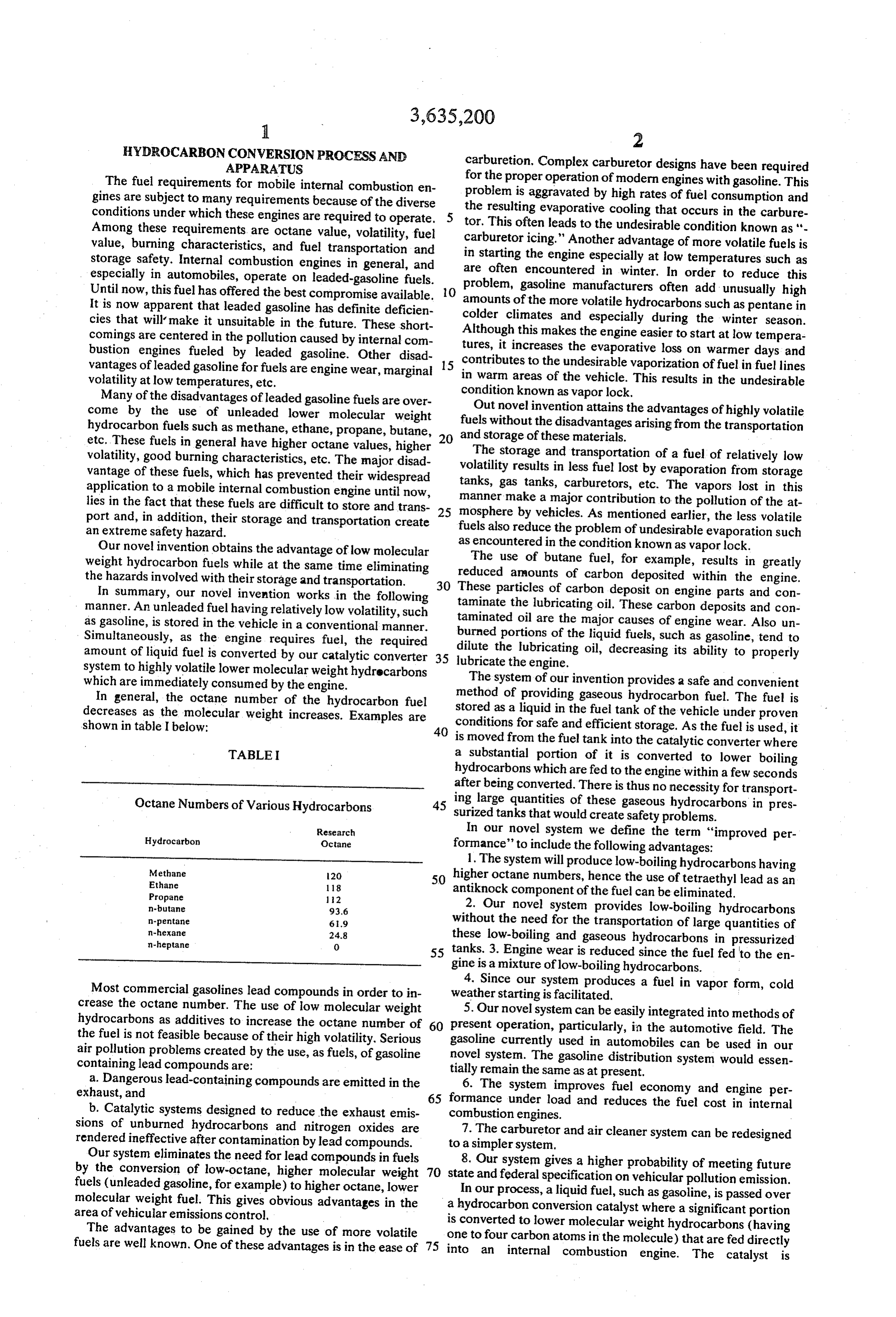
APPARATUS carburetion. Complex carburetor designs have been required The fuel requirements for mobile internal combustion en for the proper operation of modern engines with gasoline. This gines are subject to many requirements because of the diverse problem is aggravated by high rates of fuel consumption and conditions under which these engines are required to operate. tor.the resulting evaporative cooling that occurs in the carbure This often leads to the undesirable condition known as "-
Among these requirements are octane value, volatility, fuel carburetoricing."
value, burning characteristics, and fuel transportation and in starting the engine Another advantage of more volatile fuels is storage safety. Internal combustion engines in general, and are especially at low temperatures such as especially in automobiles, operate on leaded-gasoline fuels. often encountered in winter. In order to reduce this problem, gasoline manufacturers often add unusually high
Until now, this fuel has offered the best compromise available. O amounts of the more volatile hydrocarbons such as pentane in It is now apparent that leaded gasoline has definite deficien colder climates and especially during the winter season. cies that will make it unsuitable in the future. These short comings are centered in the pollution caused by internal com Although this makes the engine easier to start at low tempera bustion engines fueled by leaded gasoline. Other disad tures, it increases the evaporative loss on warmer days and vantages of leaded gasoline for fuels are engine wear, marginal 15 contributes to the undesirable vaporization of fuel in fuel lines in warm areas of the vehicle. This results in the undesirable volatility at low temperatures, etc.
Many of the disadvantages of leaded gasoline fuels are over condition known as vapor lock.
come by the use of unleaded lower molecular weight Out novel invention attains the advantages of highly volatile hydrocarbon fuels such as methane, ethane, propane, butane, 20 fuels without the disadvantages arising from the transportation etc. These fuels in general have higher octane values, higher andThe storage of these materials.
volatility, good burning characteristics, etc. The major disad volatilitystorage and transportation of a fuel of relatively low results in less fuel lost by evaporation from storage vantage of these fuels, which has prevented their widespread application to a mobile internal combustion engine until now, tanks, gas tanks, carburetors, etc. The vapors lost in this lies in the fact that these fuels are difficult to store and trans manner make a major contribution to the pollution of the at port and, in addition, their storage and transportation create 25 mosphere by vehicles. As mentioned earlier, the less volatile an extreme safety hazard. fuels also reduce the problem of undesirable evaporation such Our novel invention obtains the advantage of low molecular asThe encountered in the condition known as vapor lock. use of butane fuel, for example, results in greatly weight hydrocarbon fuels while at the same time eliminating the hazards involved with their storage and transportation. reduced amounts of carbon deposited within the engine. In summary, our novel invention works in the following These particles of carbon deposit on engine parts and con manner. An unleaded fuel having relatively low volatility, such taminate the lubricating oil. These carbon deposits and con as gasoline, is stored in the vehicle in a conventional manner. taminated oil are the major causes of engine wear. Also un Simultaneously, as the engine requires fuel, the required burned portions of the liquid fuels, such as gasoline, tend to amount of liquid fuel is converted by our catalytic converter 35 dilute the lubricating oil, decreasing its ability to properly lubricate the engine. - system to highly volatile lower molecular weight hydrocarbons which are immediately consumed by the engine. The system of our invention provides a safe and convenient In general, the octane number of the hydrocarbon fuel method of providing gaseous hydrocarbon fuel. The fuel is decreases as the molecular weight increases. Examples are stored as a liquid in the fuel tank of the vehicle under proven shown in table I below: 40 conditions for safe and efficient storage. As the fuel is used, it is moved from the fuel tank into the catalytic converter where
TABLE a substantial portion of it is converted to lower boiling hydrocarbons which are fed to the engine within a few seconds after being converted. There is thus no necessity for transport
Octane Numbers of Various Hydrocarbons 45 ing large quantities of these gaseous hydrocarbons in pres surized tanks that would create safety problems.
Hydrocarbon
Research
Octane
In our novel system we define the term “improved per formance' to include the following advantages:
1. The system will produce low-boiling hydrocarbons having
Methane 20 higher octane numbers, hence the use of tetraethyl lead as an
Propane 12 antiknock component of the fuel can be eliminated. n-butane 93.6 2. Our novel system provides low-boiling hydrocarbons n-pentane 6.9 without the need for the transportation of large quantities of
0. these low-boiling and gaseous hydrocarbons in pressurized 55 tanks. 3. Engine wear is reduced since the fuel fed to the en gine is a mixture of low-boiling hydrocarbons.
Most commercial gasolines lead compounds in order to in weather 4. Since our system produces a fuel in vapor form, cold starting is facilitated.
crease the octane number. The use of low molecular weight 5. Our novel system can be easily integrated into methods of hydrocarbons as additives to increase the octane number of 60 present operation, particularly, in the automotive field. The the fuel is not feasible because of their high volatility. Serious gasoline currently used in automobiles can be used in our air pollution problems created by the use, as fuels, of gasoline novel system. The gasoline distribution system would essen containing lead compounds are:
a. Dangerous lead-containing compounds are emitted in the tially remain the same as at present. 6. The system improves fuel economy and engine per exhaust, and 65 formance under load and reduces the fuel cost in internal b. Catalytic systems designed to reduce the exhaust emis combustion engines.
sions of unburned hydrocarbons and nitrogen oxides are 7. The carburetor and air cleaner system can be redesigned rendered ineffective after contamination by lead compounds. to a simpler system.
Our system eliminates the need for lead compounds in fuels 8. Our system gives a higher probability of meeting future by the conversion of low-octane, higher molecular weight 70 state and federal specification on vehicular pollution emission. fuels (unleaded gasoline, for example) to higher octane, lower In our process, a liquid fuel, such as gasoline, is passed over molecular weight fuel. This gives obvious advantages in the a hydrocarbon conversion catalyst where a significant portion area of vehicular emissions control, is converted
The advantages to be gained by the use of more volatile one to four carbon to lower molecular weight hydrocarbons (having atoms in the molecule) that are fed directly fuels are well known. One of these advantages is in the ease of 75 into an internal combustion engine. The catalyst is
Page 10
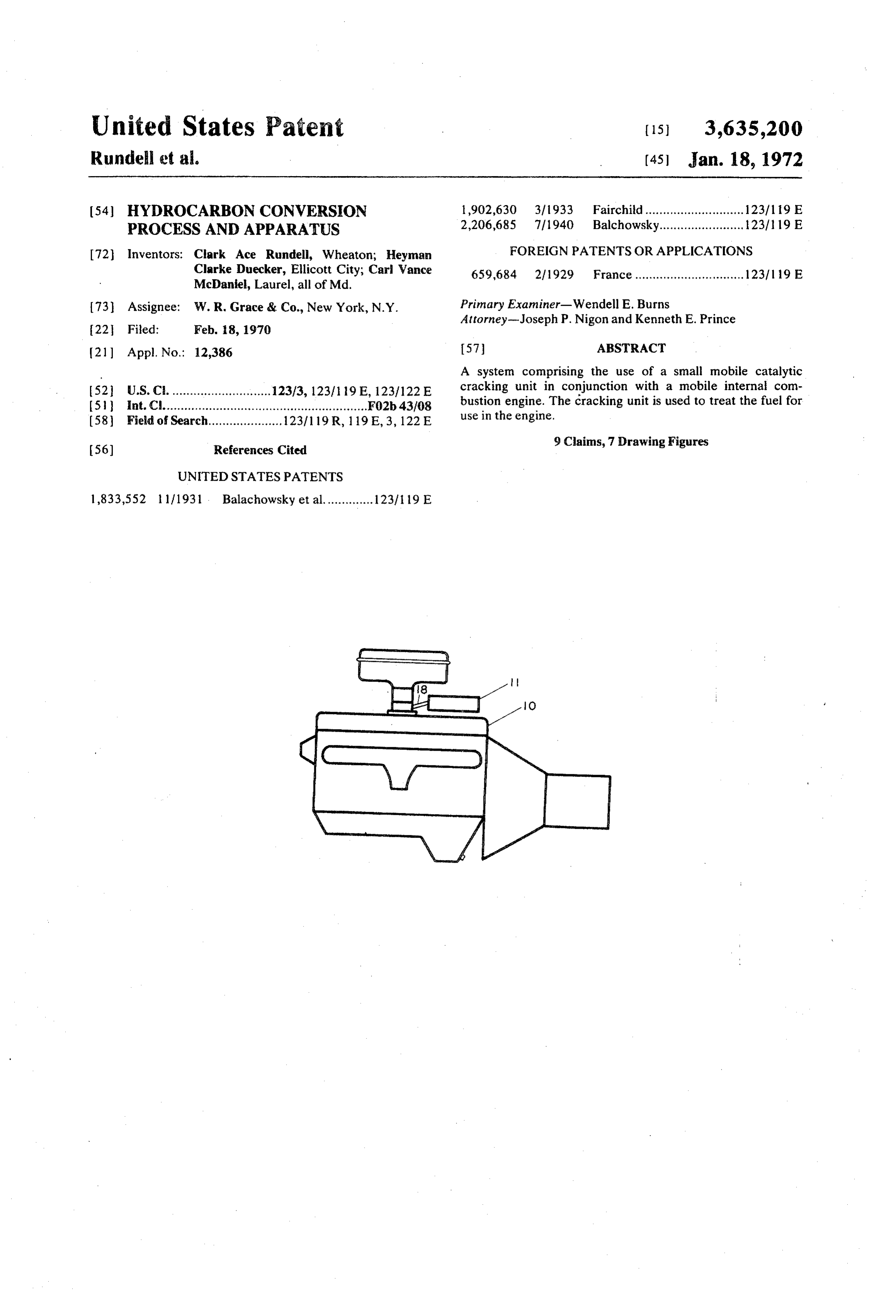
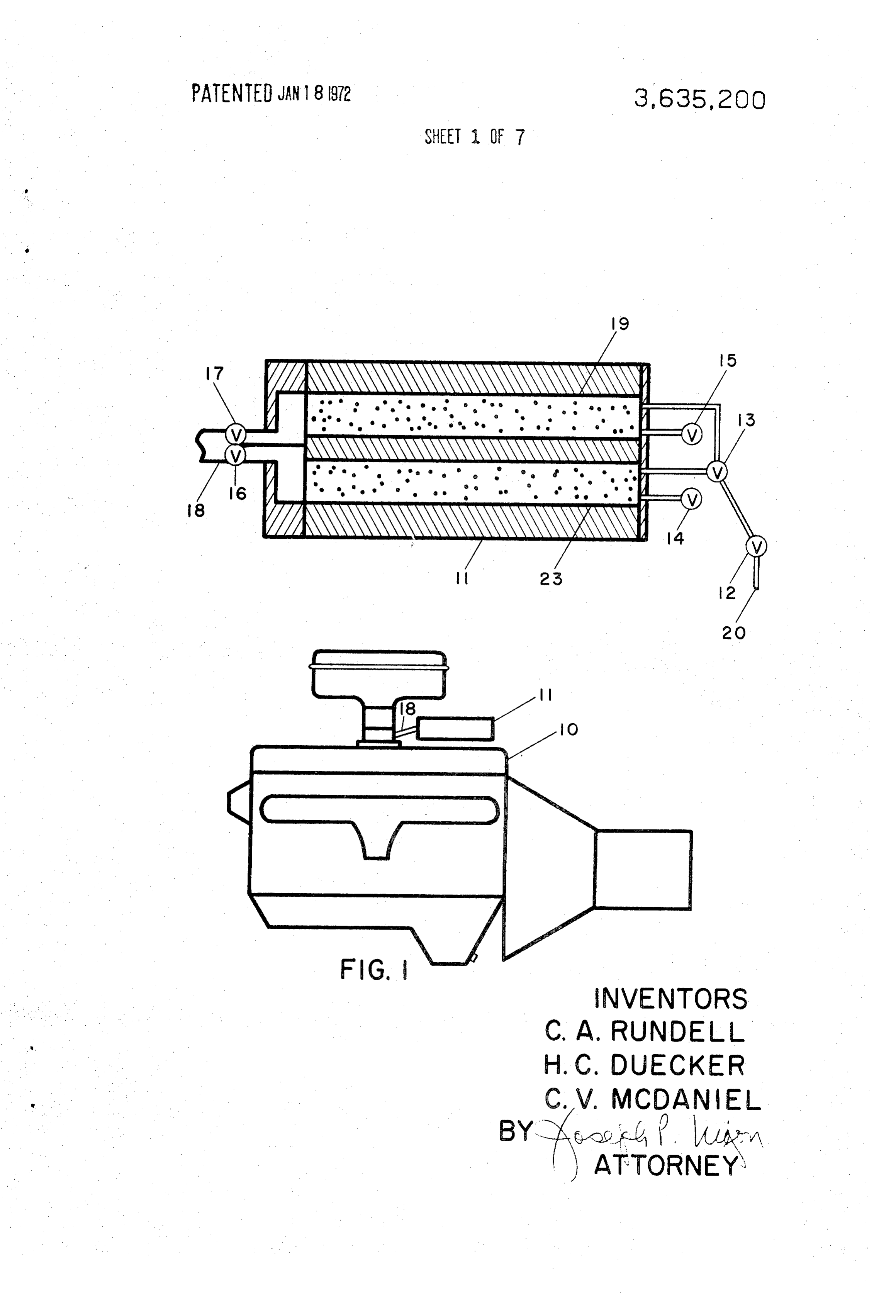
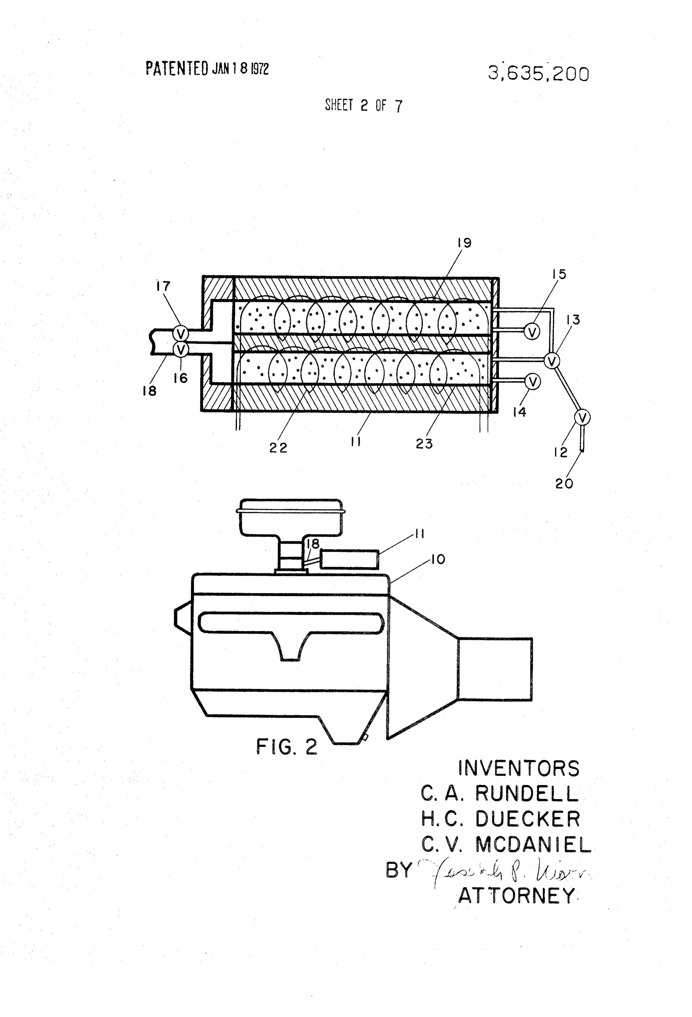
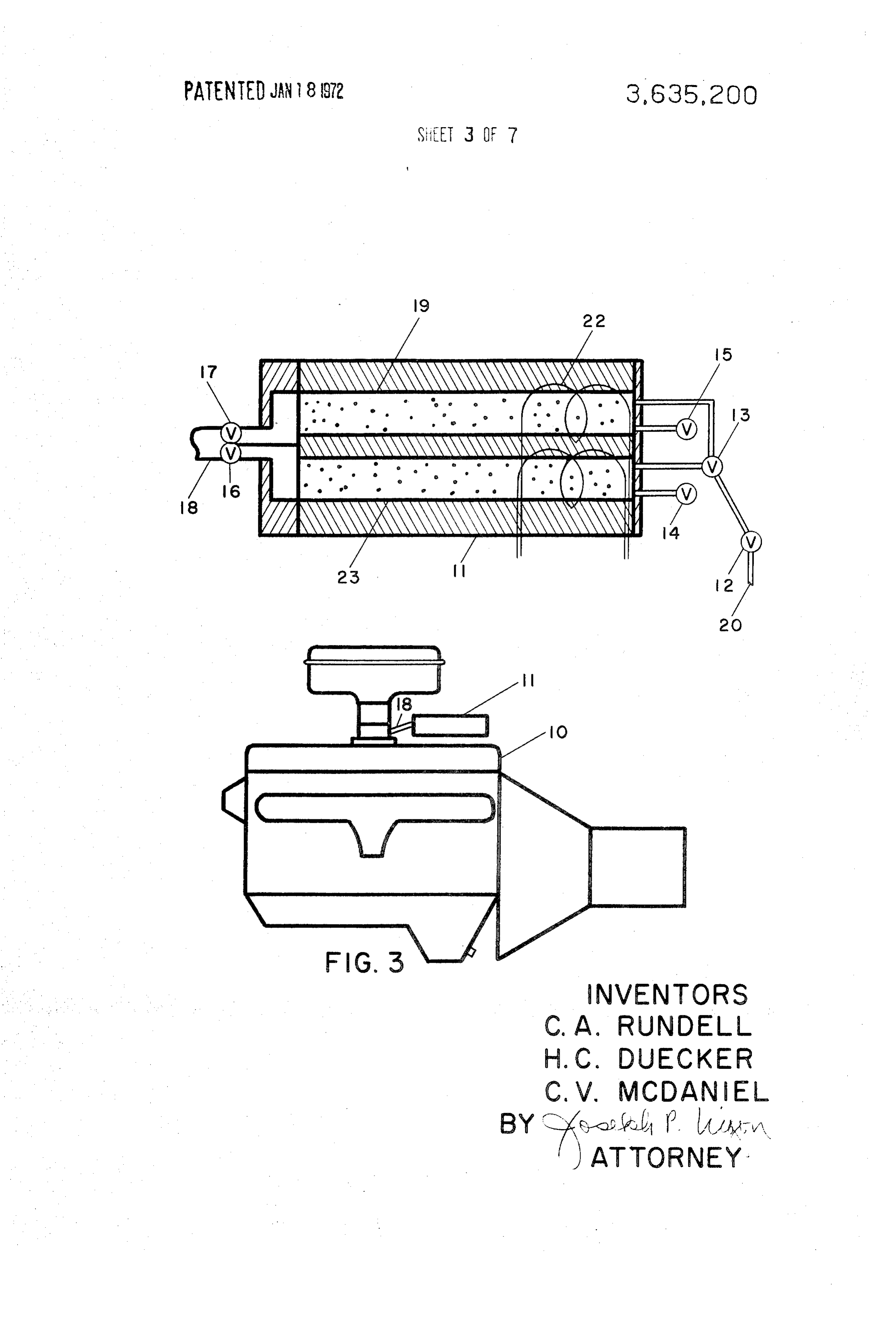
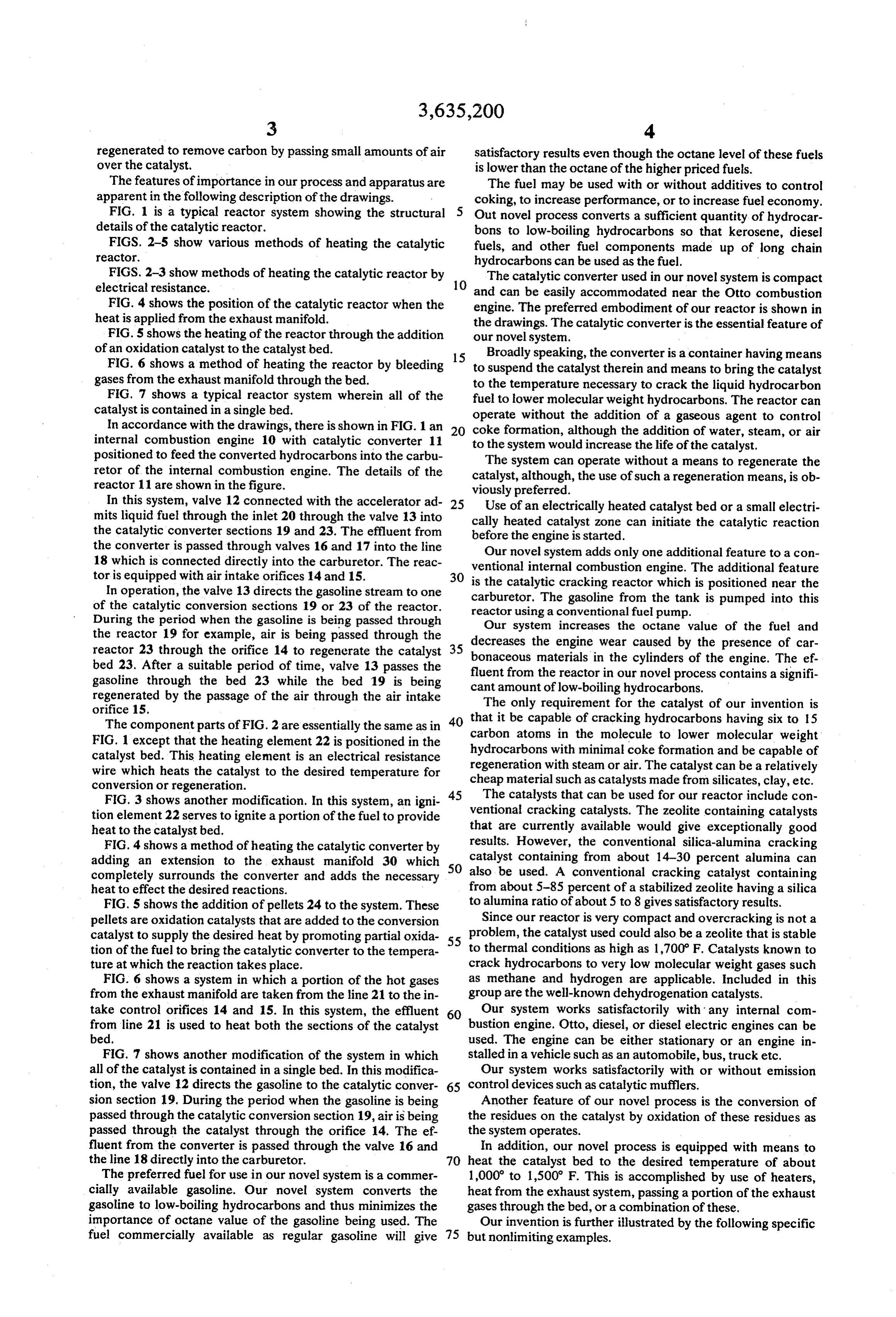
regenerated to remove carbon by passing small amounts of air satisfactory results even though the octane level of these fuels over the catalyst, is lower than the octane of the higher priced fuels. The features of importance in our process and apparatus are The fuel may be used with or without additives to control apparent in the following description of the drawings. coking, to increase performance, or to increase fuel economy. FIG. 1 is a typical reactor system showing the structural 5 Out novel process converts a sufficient quantity of hydrocar details of the catalytic reactor. bons to low-boiling hydrocarbons so that kerosene, diesel FIGS. 2-5 show various methods of heating the catalytic fuels, and other fuel components made up of long chain reactor. hydrocarbons can be used as the fuel.
FIGS. 2-3 show methods of heating the catalytic reactor by The catalytic converter used in our novel system is compact electrical resistance. 10 and can be easily accommodated near the Otto combustion
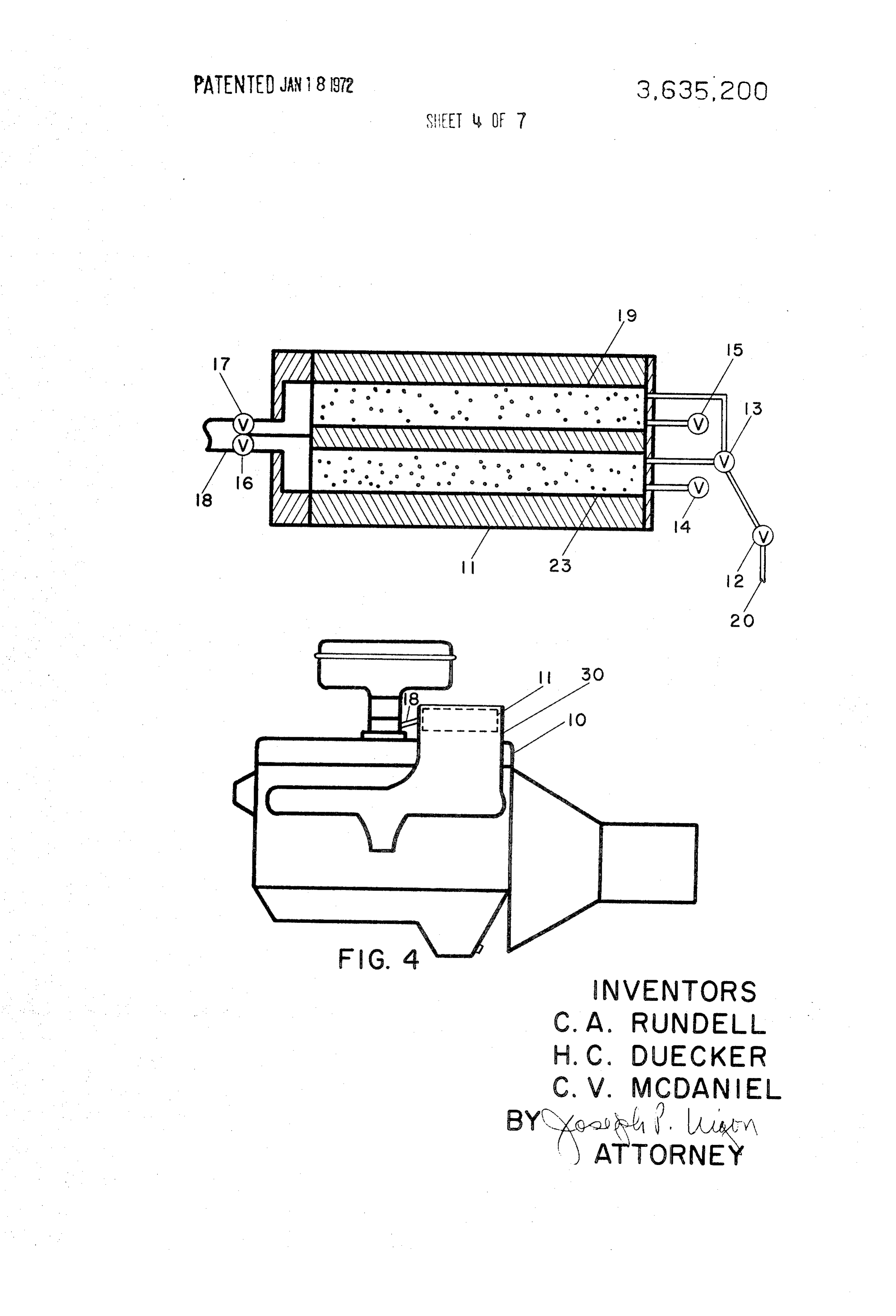
FIG. 4 shows the position of the catalytic reactor when the engine. The preferred embodiment of our reactor is shown in heat is applied from the exhaust manifold. the drawings. The catalytic converter is the essential feature of FIG. 5 shows the heating of the reactor through the addition our novel system.
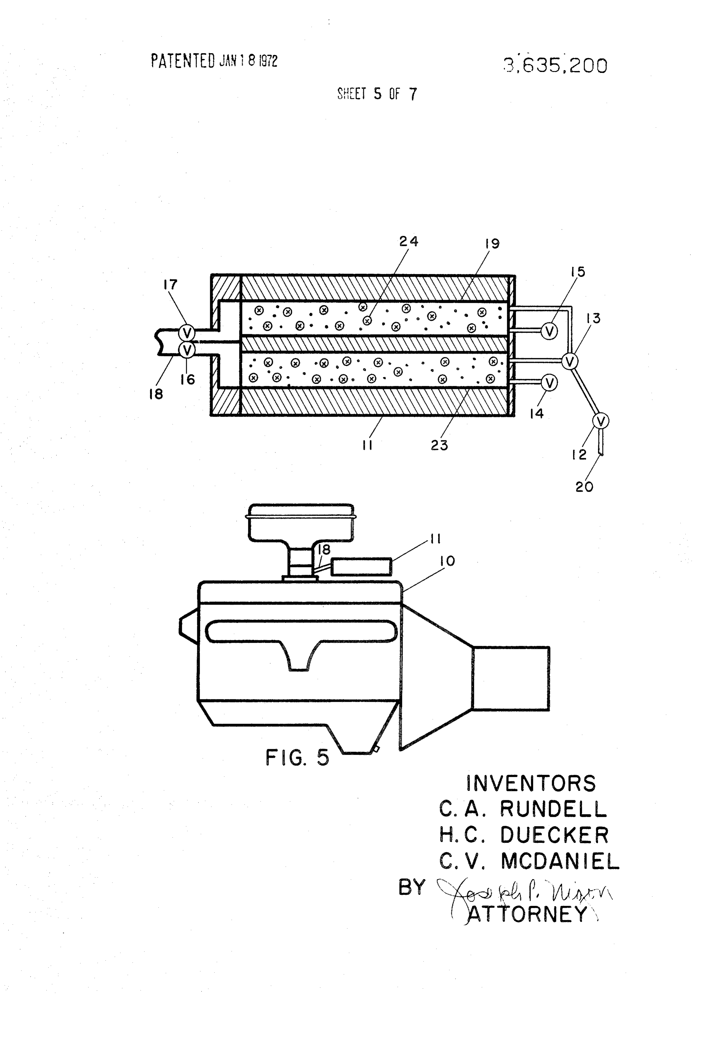
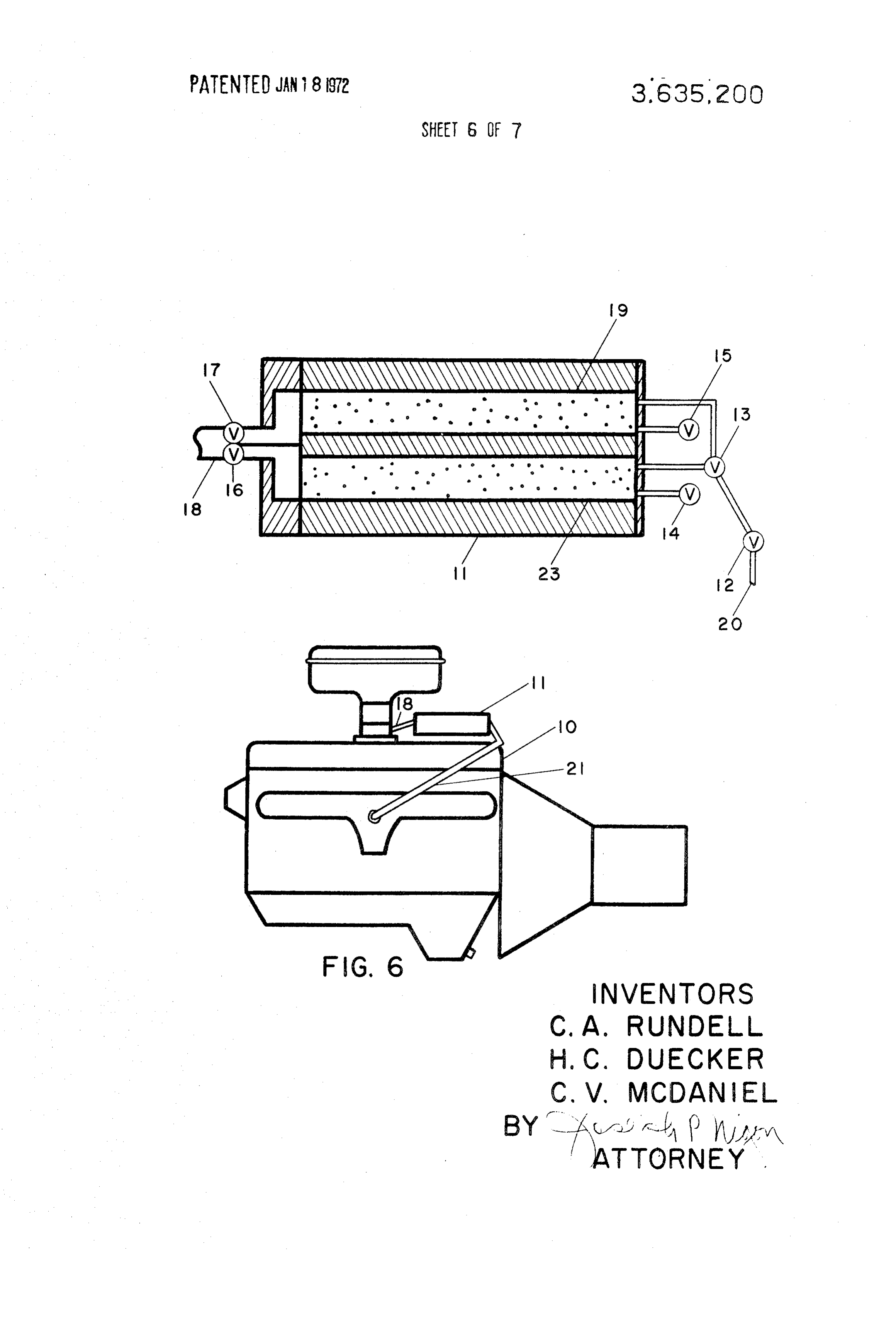
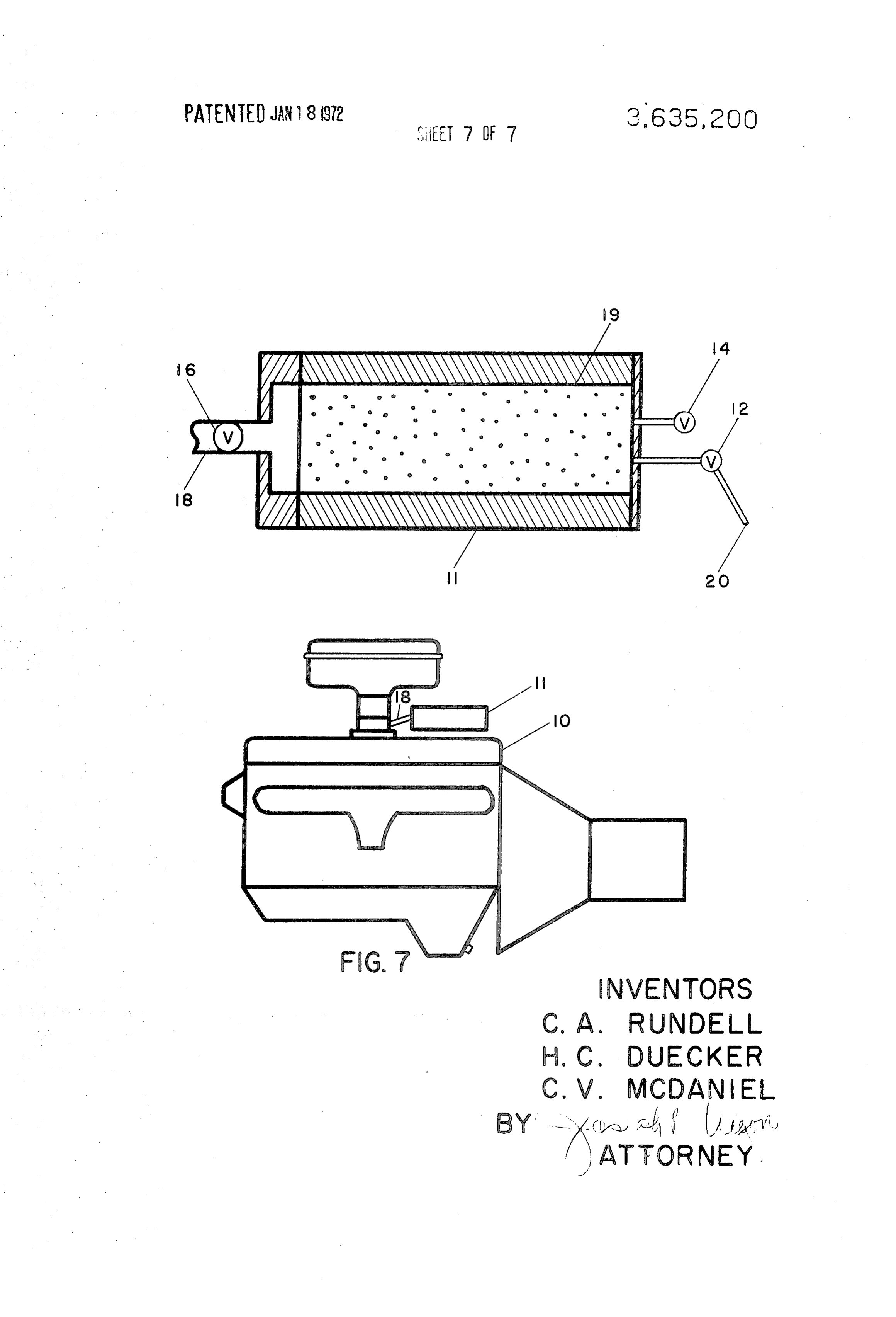
of an oxidation catalyst to the catalyst bed. 15 Broadly speaking, the converter is a container having means FIG. 6 shows a method of heating the reactor by bleeding to suspend the catalyst therein and means to bring the catalyst gases from the exhaust manifold through the bed. to the temperature necessary to crack the liquid hydrocarbon FIG. 7 shows a typical reactor system wherein all of the fuel to lower molecular weight hydrocarbons. The reactor can catalyst is contained in a single bed. operate without the addition of a gaseous agent to control In accordance with the drawings, there is shown in FIG. 1 an 20 coke formation, although the addition of water, steam, or air internal combustion engine 10 with catalytic converter 11 positioned to feed the converted hydrocarbons into the carbu to The the system would increase the life of the catalyst. system can operate without a means to regenerate the retor of the internal combustion engine. The details of the catalyst, although, the use of such a regeneration means, is ob reactor 11 are shown in the figure. viously preferred.
In this system, valve 12 connected with the accelerator ad 25 Use of an electrically heated catalyst bed or a small electri mits liquid fuel through the inlet 20 through the valve 13 into cally heated catalyst zone can initiate the catalytic reaction the catalytic converter sections 19 and 23. The effluent from before the engine is started.
the converter is passed through valves 16 and 17 into the line Our novel system adds only one additional feature to a con 18 which is connected directly into the carburetor. The reac ventional internal combustion engine. The additional feature tor is equipped with air intake orifices 14 and 15. 30 is the catalytic cracking reactor which is positioned near the In operation, the valve 13 directs the gasoline stream to one carburetor. The gasoline from the tank is pumped into this of the catalytic conversion sections 19 or 23 of the reactor. reactor using a conventional fuel pump. During the period when the gasoline is being passed through Our system increases the octane value of the fuel and the reactor 19 for example, air is being passed through the decreases the engine wear caused by the presence of car reactor 23 through the orifice 14 to regenerate the catalyst 35 bonaceous materials in the cylinders of the engine. The ef. bed 23. After a suitable period of time, valve 13 passes the fluent from the reactor in our novel process contains a signifi gasoline through the bed 23 while the bed 19 is being cant amount of low-boiling hydrocarbons. regenerated by the passage of the air through the air intake The only requirement for the catalyst of our invention is orifice 15.
The component parts of FIG. 2 are essentially the same as in 40 that it be capable of cracking hydrocarbons having six to 15 FIG. 1 except that the heating element 22 is positioned in the carbon atoms in the molecule to lower molecular weight catalyst bed. This heating element is an electrical resistance hydrocarbons with minimal coke formation and be capable of wire which heats the catalyst to the desired temperature for regeneration with steam or air. The catalyst can be a relatively conversion or regeneration. cheap material such as catalysts made from silicates, clay, etc. The catalysts that can be used for our reactor include con
FIG. 3 shows another modification. In this system, an igni 45 ventional tion element 22 serves to ignite a portion of the fuel to provide cracking catalysts. The zeolite containing catalysts heat to the catalyst bed. that are currently available would give exceptionally good FIG. 4 shows a method of heating the catalytic converter by results. However, the conventional silica-alumina cracking adding an extension to the exhaust manifold 30 which 50 catalyst containing from about 14-30 percent alumina can also be used. A conventional cracking catalyst containing completely surrounds the converter and adds the necessary heat to effect the desired reactions. from about 5-85 percent of a stabilized zeolite having a silica FIG. 5 shows the addition of pellets 24 to the system. These to alumina ratio of about 5 to 8 gives satisfactory results. pellets are oxidation catalysts that are added to the conversion Since our reactor is very compact and overcracking is not a catalyst to supply the desired heat by promoting partial oxida 55 problem, the catalyst used could also be a zeolite that is stable tion of the fuel to bring the catalytic converter to the tempera to thermal conditions as high as 1,700 F. Catalysts known to ture at which the reaction takes place. crack hydrocarbons to very low molecular weight gases such FIG. 6 shows a system in which a portion of the hot gases as methane and hydrogen are applicable. Included in this from the exhaust manifold are taken from the line 21 to the in group are the well-known dehydrogenation catalysts. take control orifices 14 and 15. In this system, the effluent 60 Our system works satisfactorily with any internal com from line 21 is used to heat both the sections of the catalyst bustion engine. Otto, diesel, or diesel electric engines can be bed. used. The engine can be either stationary or an engine in FIG. 7 shows another modification of the system in which stalled in a vehicle such as an automobile, bus, truck etc. all of the catalyst is contained in a single bed. In this modifica Our system works satisfactorily with or without emission tion, the valve 2 directs the gasoline to the catalytic conver 65 control devices such as catalytic mufflers. sion section 19. During the period when the gasoline is being Another feature of our novel process is the conversion of passed through the catalytic conversion section 19, air is being the residues on the catalyst by oxidation of these residues as passed through the catalyst through the orifice 14. The ef the system operates.
fluent from the converter is passed through the valve 16 and In addition, our novel process is equipped with means to the line 18 directly into the carburetor. 70 heat the catalyst bed to the desired temperature of about The preferred fuel for use in our novel system is a commer 1,000 to 1,500 F. This is accomplished by use of heaters, cially available gasoline. Our novel system converts the heat from the exhaust system, passing a portion of the exhaust gasoline to low-boiling hydrocarbons and thus minimizes the gases through the bed, or a combination of these. importance of octane value of the gasoline being used. The Our invention is further illustrated by the following specific fuel commercially available as regular gasoline will give 75 but nonlimiting examples.
Page 11
S 6
EXAMPLE 1. EXAMPLE 4
This example demonstrates that a reasonably large amount The maximum power output obtainable from the operation of liquid fuel can be cracked to lower molecular weight of the engine on cracked and uncracked heptane was deter molecules without regeneration. mined using the device and engine described in the previous A total of 25 grams of a synthetic gasoline were prepared by examples. To test the maximum power output of the engine, mixing 50 percent n-heptane, 25 percent toluene and 25 per the throttle on the carburetor was opened fully and the fuel cent n-octane. The mixture was passed over 5 grams of a flow through the device was adjusted to give the maximum zeolite-containing catalyst heated to about 900 F. The sustainable power output. The first test was carried out with cracked product was collected in 5 ml. portions in a cold trap, 10 operation of engine on uncracked heptane. The heptane was cooled by liquid nitrogen. The analysis of the collected sam passed through an empty catalyst chamber. It was observed ples was determined by slowly warming the sample and allow that the maximum power output obtainable was 30-60 watts ing it to vaporize. A major portion of the product had a boiling with a fuel flow of 12-13 cubic centimeters of liquid heptane point below room temperature indicating that: E. minute.
eptane The through passed next testawas done using chamber catalyst-filled cracked heptane heated to 1. A large amount of cracking was still occurring at the end 15 1,100 F-to operate the engine. It was found that 300-500 of the experiment, and 2. The cracking product contained large amounts of volatile centimeters of liquid heptane per minute. It was observedcubic watts of power was obtainable at a fuel flow of 10-11 that molecules. the maximum power output was sustainable for extended A very small amount, on the order of only 2 percent of the 20 periods of time.
original gasoline, was converted to coke in the process. What is claimed is:
EXAMPLE 2
1. A method of reducing engine wear and improving the performance of an internal combustion engine which com
This example illustrates the operation of a 2% horsepower, prises contacting a liquid hydrocarbon fuel in the absence of air with a catalyst in a catalytic converter under hydrocarbon 1-cylinder Otto engine on heptane fuel using the catalytic 25 cracking cracking device to crack the fuel immediately before admis conditions and mixing the lower boiling hydrocar bons formed sion into the intake manifold of the engine. Conditions for fuel inlet of said with air and passing said hydrocarbons into the operation of the engine and device were: internal combustion engine. The device was maintained by use of an electrical heater at bon2. fuel The process according to claim 1 wherein said hydrocar a temperature of 1,100 F. in the catalyst bed during the 30 F. range. is a hydrocarbon fraction boiling in the 100 to 700 cracking operation. The fueled rate through the catalyst bed 3. The process according to claim 1 wherein said fuel is an was about 11 cubic centimeters per minute of heptane. The unleaded gasoline.
fuel used was normal heptane. The catalyst used was a rare 4. A method of improving the performance of an internal earth exchanged Type Y zeolite. The quantity of catalyst used combustion engine which comprises:
in a catalyst chamber was approximately 6 grams. The form of 35 a. Selecting a hydrocarbon fuel boiling in the range of the catalyst was %-inch pellets. The catalyst device consisted 100-700°F., of four chambers of about 10 cubic centimeters volume each. b. contacting said fuel with a catalyst in the absence of air in Two of the chambers were filled with catalysts. Two of the a catalytic converter heated to about 500 to 1,500 F. to chambers were left empty. The device was operated on only 40 convert a substantial portion of said fuel to gaseous one chamber at any time. Air was fed through the chambers at hydrocarbons having about one to five carbon atoms in approximately 500 cubic centimeters per minute continuously the molecule, and during the operation of the device. The engine was connected c. mixing said hydrocarbons with air and passing said mix by belt to an electric generator. The electrical generator was ture into the fuel intake system of said internal com connected to a heater for dissipation of energy. 45 bustion engine.
5. The process according to claim 4 wherein the catalyst is a
EXAMPLE 3 hydrocarbon-cracking catalyst selected from the group con
The engine described above was observed to operate nicely 30 sisting of clay, alumina, silica-alumina containing about 15 to percent alumina, and zeolite promoted silica-alumina.
under conditions of no load on heptane and on cracked hep 6. The process according to claim 5 wherein the catalyst is a
tane. The application of a small load of about 5 watts of power zeolitic catalyst containing about 5 to 15 percent zeolite to the engine produced severe knocking when the engine was dispersed within and throughout a silica-alumina base. operated on uncracked heptane. Operation of the engine on 7. The process according to claim 4 wherein the catalyst is a uncracked heptane was done by simply feeding the fuel faujasite type zeolite having a silica-to-alumina ratio of about through an empty catalyst chamber. Operation of the engine 3 to 8.
on cracked heptane, that is heptane which was passed through 55 8. The process according to claim 4 wherein the fuel is lead a catalyst-containing chamber under the standard operating free. | conditions showed that the engine operated well with no 9. The process according to claim 4 wherein the fuel is fed knocking observed upon application of a load in excess of 300 to said internal combustion engine through a carburetor. Watts, it k k X: it
Provenance
- Collection
- Cited prior art
- Original PDF
- patentimages.storage.googleapis.com →
- Filed
- 1970-02-18
- Pages
- 11
- Method
- pdftotext (the PDF's own text layer) + pdftoppm 300dpi page scans
- Source
- Google Patents bibliographic record
- Granted
- 1972-01-18
- Inventors
- Clark Ace Rundell; Heyman Clarke Duecker; Carl Vance Mcdaniel; WR Grace and Co
- Transcribed from
- patentimages.storage.googleapis.com →