patent · US3982910
Hydrogen-rich gas generator
28 September 1976
Page 1 — bibliographic record
United States Patent (19) 11 3,982,910 Houseman et al. (45) Sept. 28, 1976 54 HYDROGEN-RICH GAS GENERATOR 296,785 12/1929 United Kingdom................... 48.1212 75 Inventors: John Houseman, Pasadena; Donald
J. Cerini, Flintridge, both of Calif. Primary Examiner-Robert L. Lindsay, Jr. 73 Assignee: The United States of America as Assistant Examiner-George C. Yeung represented by the Administrator of Attorney, Agent, or Firm-Monte F. Mott; Wilfred the National Aeronautics and Space Grifka; John R. Manning
Administration, Washington, D.C.
22 Filed: July 10, 1974 (57) ABSTRACT
A process and apparatus are described for producing hydrogen-rich product gases by mixing a spray of liq (52) U.S. Cl....................................... 48/61; 23/281; uid hydrocarbon with a stream of air in a startup pro 48/16; 48/117; 48/197 R; 48/212; 123/3; cedure and the mixture is ignited for partial oxidation, 252/373; 423/650; 431/11; 431/41; 431/1 16; then the stream of air is heated by the resulting com 431/162; 431/170 bustion to reach a temperature such that a signal is 51 Int. Cl’............................................. B01J 7700 produced. The signal triggers a two way valve which (58 Field of Search............... 48/1 16, 17, 118, 61, directs liquid hydrocarbon from a spraying mechanism 48/63, 212, 197 R, 213; 23/28, 288 H, 288 to a vaporizing mechanism with which a vaporized hy K; 423/650; 123/1 A, 3; 252/373; 431/11, drocarbon is formed. The vaporized hydrocarbon is 41, DIG. 65, DIG. 68, 116, 162, 170 subsequently mixed with the heated air in the combus References Cited tion chamber where partial oxidation takes place and 56 hydrogen-rich product gases are produced.
FOREIGN PATENTS OR APPLICATIONS
5,510/27 l/1927 - Australia............................... 48.12 12 17 Claims, 10 Drawing Figures
Pao, 28. so 6 38 12.
SOURCE or
Fus
Page 2
Drawing sheet — no readable text.
Page 3
Drawing sheet — no readable text.
Page 4
Drawing sheet — no readable text.
Page 5
Drawing sheet — no readable text.
Page 6
Drawing sheet — no readable text.
Page 7
Drawing sheet — no readable text.
Page 8
Drawing sheet — no readable text.
Page 9
Drawing sheet — no readable text.
Page 10
mixing a part of the product gas, which is obtained,
HYDROGEN-RICH GAS GENERATOR with the preheated air which is being fed into the hy ORIGIN OF THE INVENTION drogen generator. Alternative to the product gas, some of the lean engine exhaust gas may be mixed with the
The invention described herein was made in the per 5 preheated air to improve the product yield. formance of work under a NASA contract and is sub Finally, and preferably, lower air fuel ratios are pro ject to the provisions of section 305 of the National vided at lower operating temperatures by passing the Aeronautics and Space Act of 1958, Public Law products of the combustion chamber in the hydrogen 85-568 (72 STAT. 435; 42USC457). reactor through a nickel catalyst bed where flameless O partial oxidation of the fuel takes place on the surface
BACKGROUND OF THE INVENTION of the catalyst to produce a hydrogen-rich gas. This invention relates to means for generating hydro The novel reactor itself is substantially cylindrical in gen-rich gas and more particularly to improvements shape having provision for preheating the incoming air therein. with the outgoing product gas. By means of the novel In an application for patent by J. Rupe entitled, "Sys 5 fuel injection arrangement, while the generator is start tem for Minimizing Internal Combustion Engine Pollu ing up, the hydrogen fuel is injected into the combus tion Emission,” Ser. No. 387,342 filed Aug. 10, 1973, tion chamber as a fine atomized spray. When the tem and assigned to a common assignee, there is described perature of the preheated air indicates that the com an arrangement for minimizing the pollution produced bustion chamber has reached a proper operating tem by an internal combustion engine by mixing hydrogen 20 perature, the heat of the combustion chamber is used with a very lean fuel/air mixture which is then injected to vaporize the liquid fuel which is thereafter mixed into the engine to be used as the engine fuel. For the with the incoming air and product gas or exhaust gas. purpose of generating the hydrogen, in that application The novel features of the invention are set forth with and in an application by Houseman et al, Ser. No. particularity in the appended claims. The invention will 390,049, filed Aug. 20, 1973, for a “Hydrogen-Rich 25 best be understood from the following description Gas Generator," and also in an application by House when read in conjunction with the accompanying draw
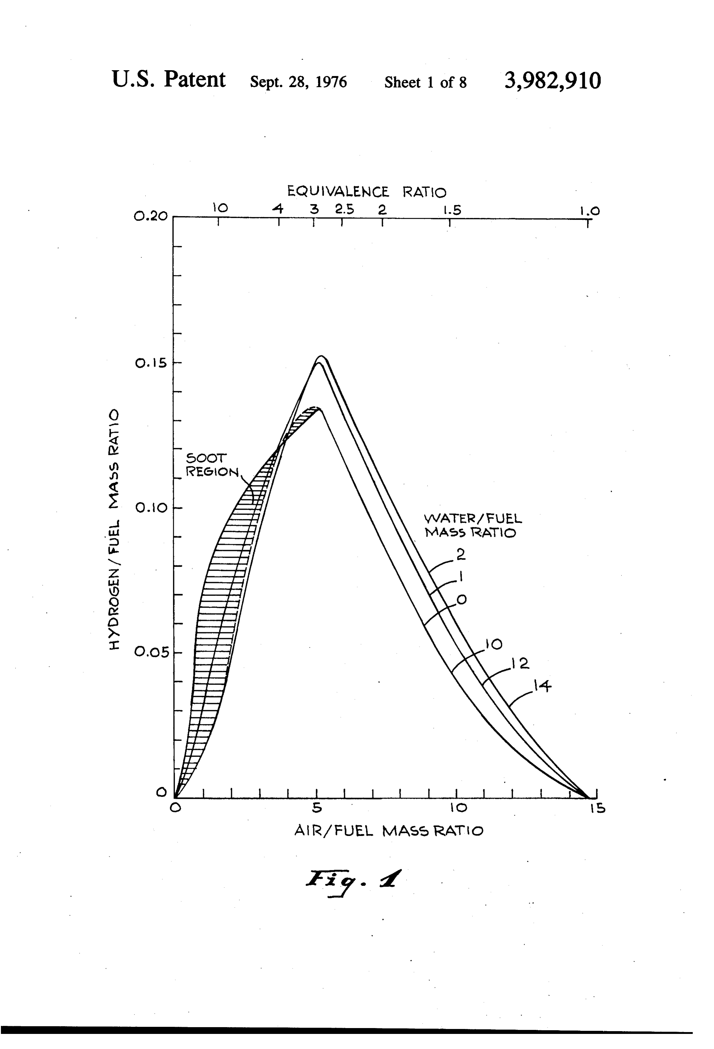
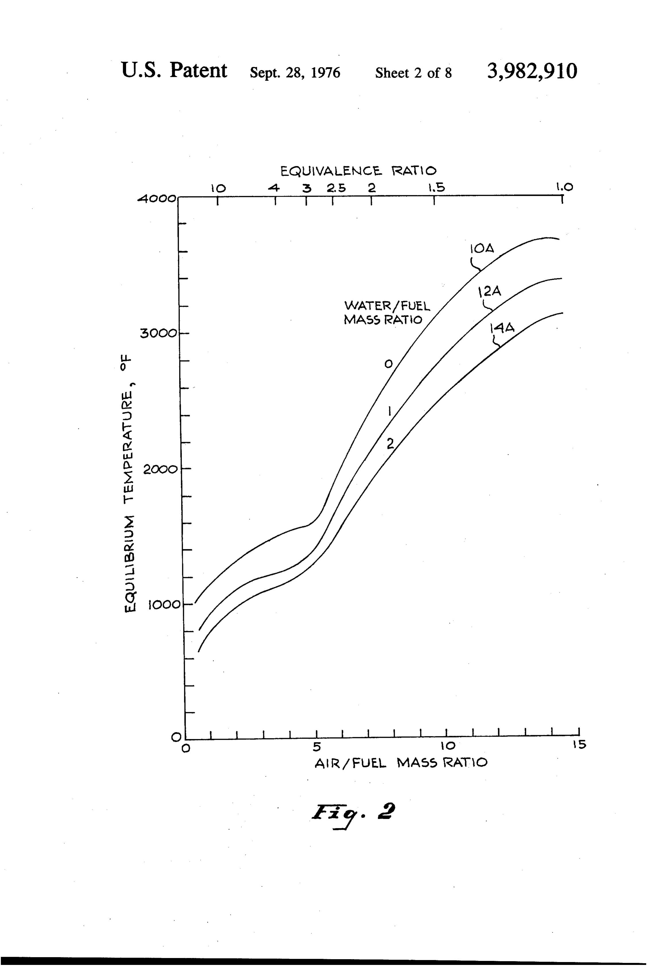
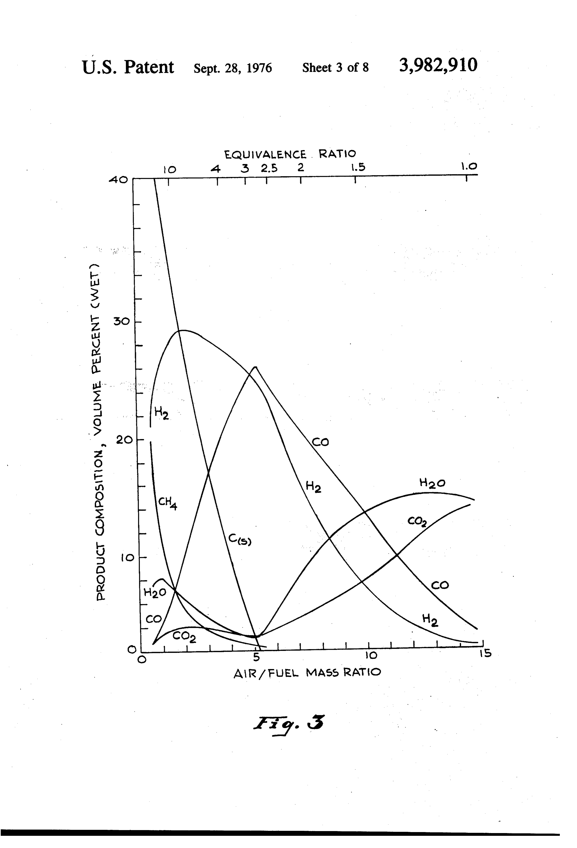
drogen-Rich Gas Generator," all of which applications BRIEF DESCRIPTION OF THE DRAWINGS are assigned to a common assignee, there are described hydrogen generators of a type which are suitable for 30 FIG. 1 is a curve illustrating the theoretical yield of use with an automobile internal combustion engine. hydrogen that can be obtained from the adiabatic com These hydrogen generators partially oxidize a spray of bustion of mixtures of air, hydrocarbon and water. atomized liquid hydrocarbon fuel in an air-steam mix FIG. 2 are curves which show the adiabatic flame ture, to produce a substantially soot-free hydrogen-rich temperature as a function of the air/fuel mass ratio, and gas. The use of steam and or water requires a water 35 for water/fuel mass ratios of 0, 1 and 2. tank to be carried by the vehicle, whose size has been FIG. 3 is a set of curves showing the distribution of estimated on the order of five gallons. The additional the various species as a function of the air/fuel ratio, cost of a water tank and the cost of providing service when no water is added.
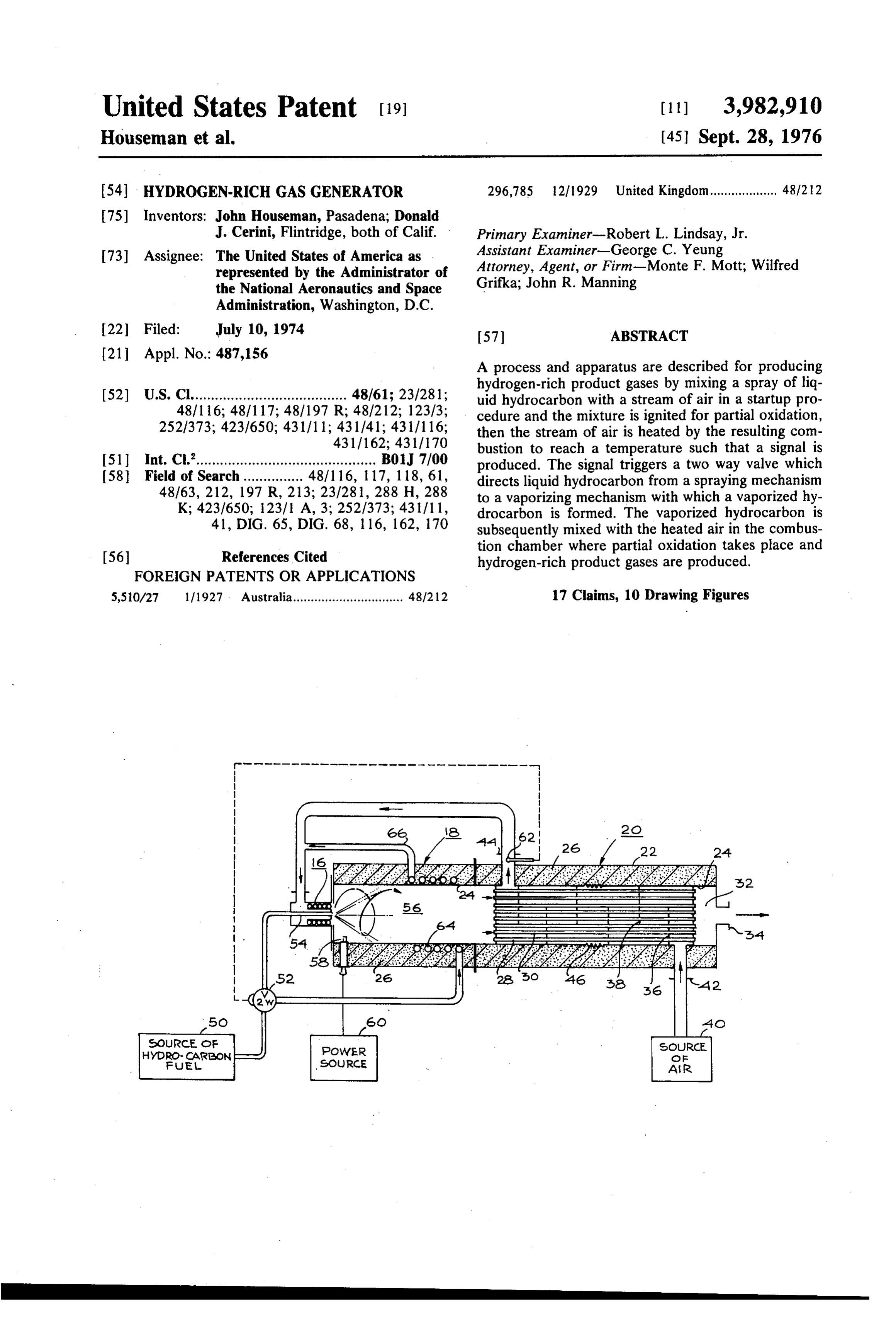
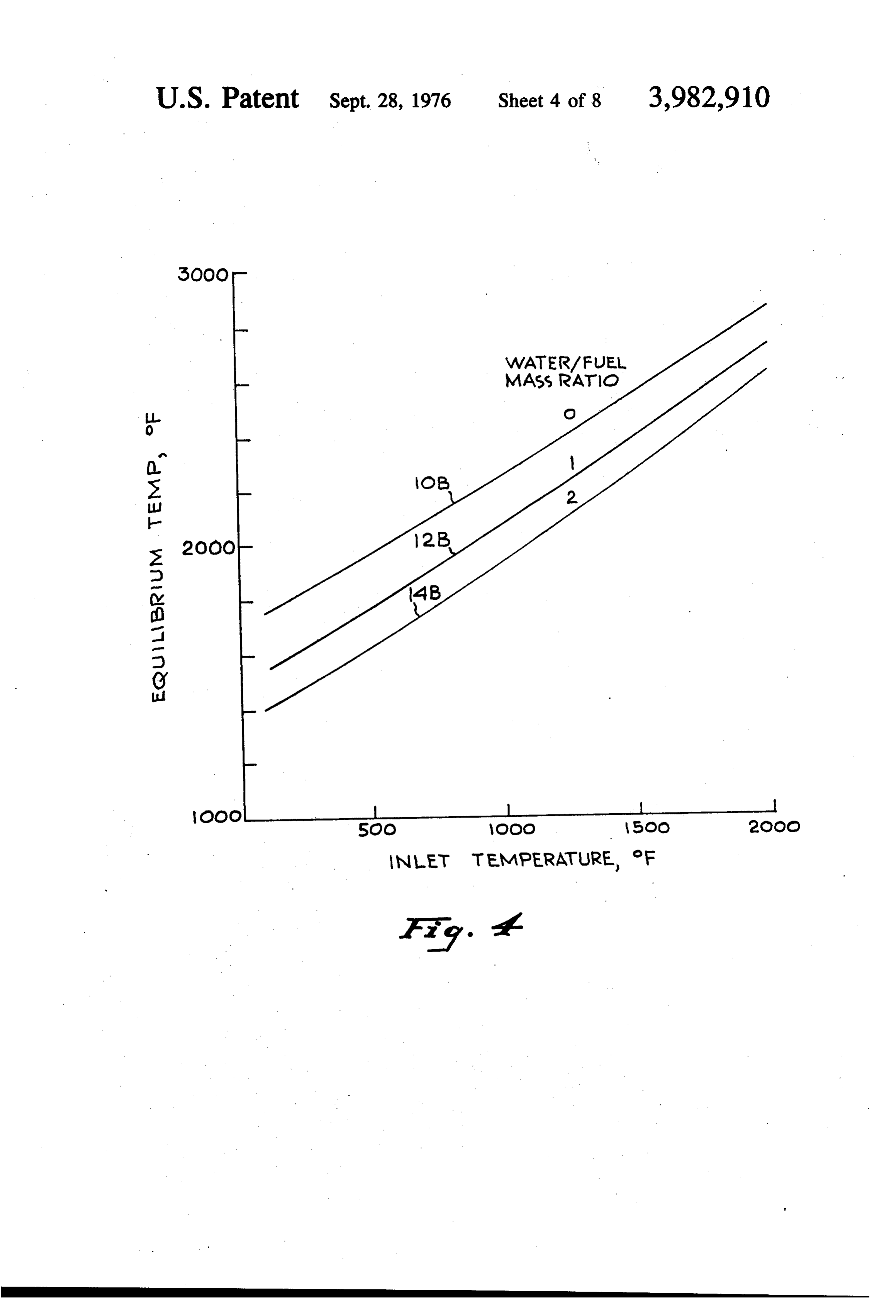
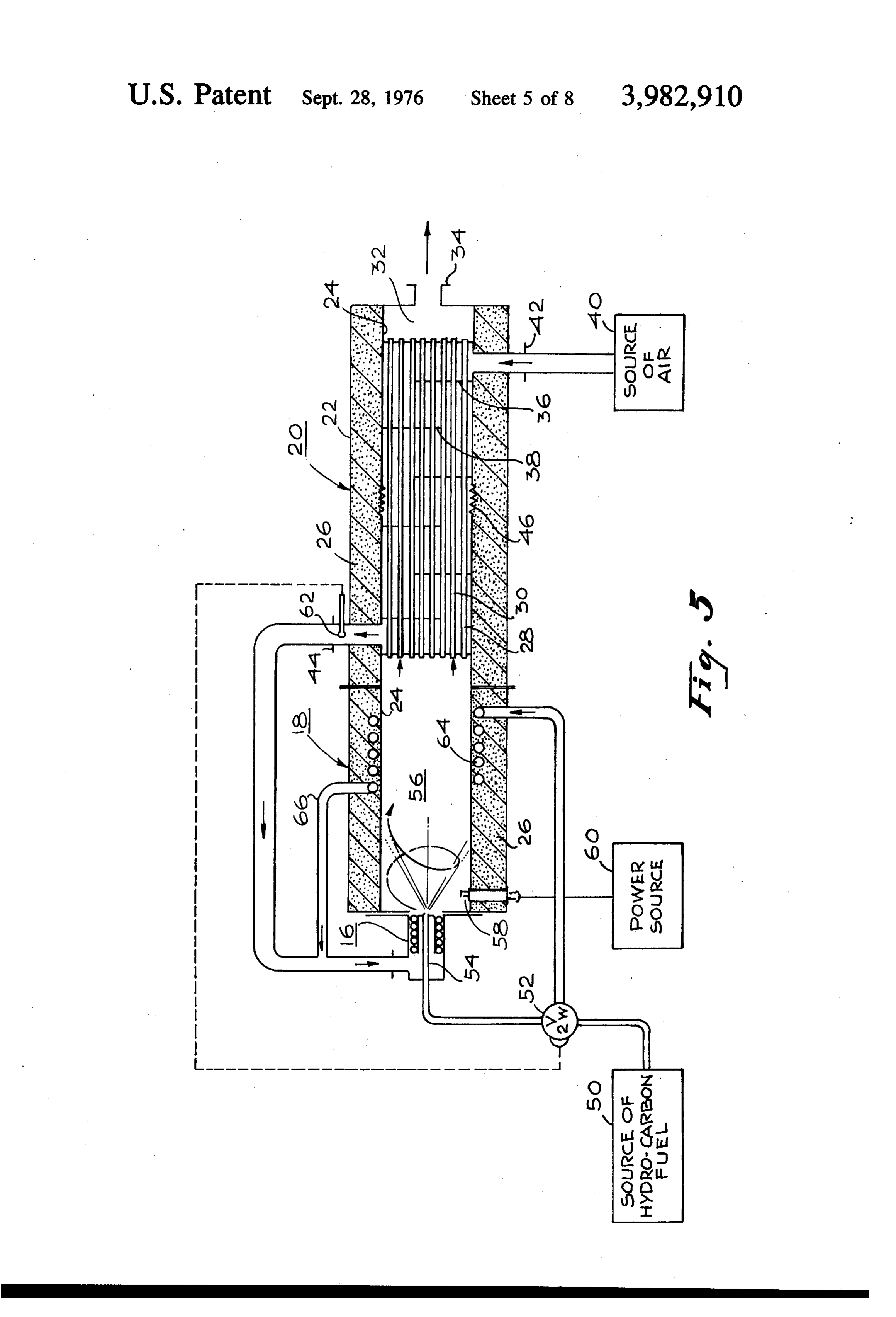
station facilities for refilling the tank with pure water 40 FIG. 4 is a series of curves showing the effect of the represents a considerable investment. Also, in cold air preheat on the final equilibrium temperature. weather the addition of a suitable anti-freeze agent to FIG. 5 illustrates in cross section, an embodiment of the water and the use of heaters to prevent freezing of a hydrogen generator, in accordance with this inven the water provides another complication which can be tion.
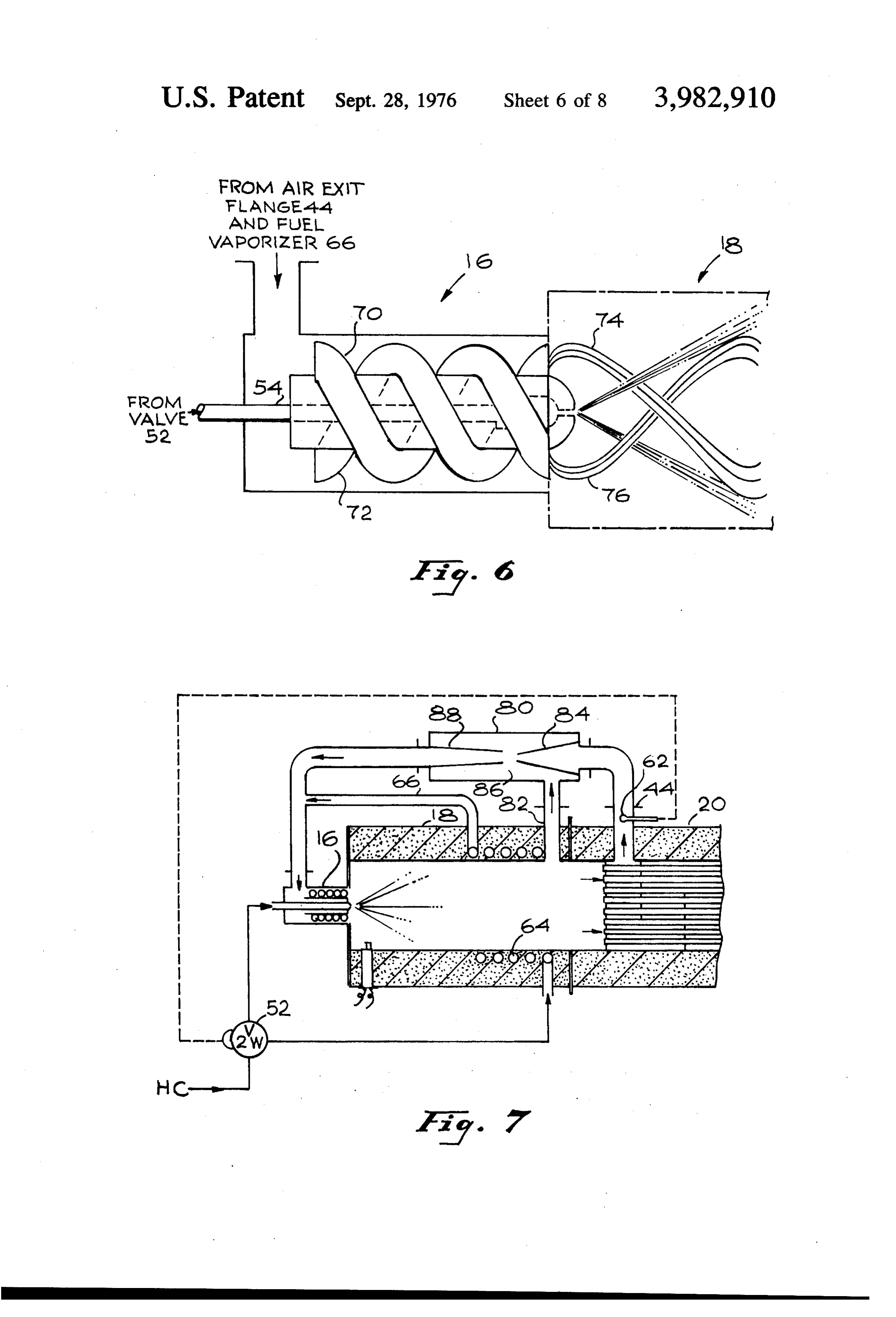
expensive. These complications may be avoided if it FIG. 6 is a view in cross section illustrating the type were possible to provide a hydrogen gas generator 45 of injection nozzle employed with this invention. which does not require water or steam, and which can FIG. 7 is a cross sectional view illustrating an em still produce either substantially or completely soot bodiment of the invention which feeds back product free hydrogen-rich gas. gas.
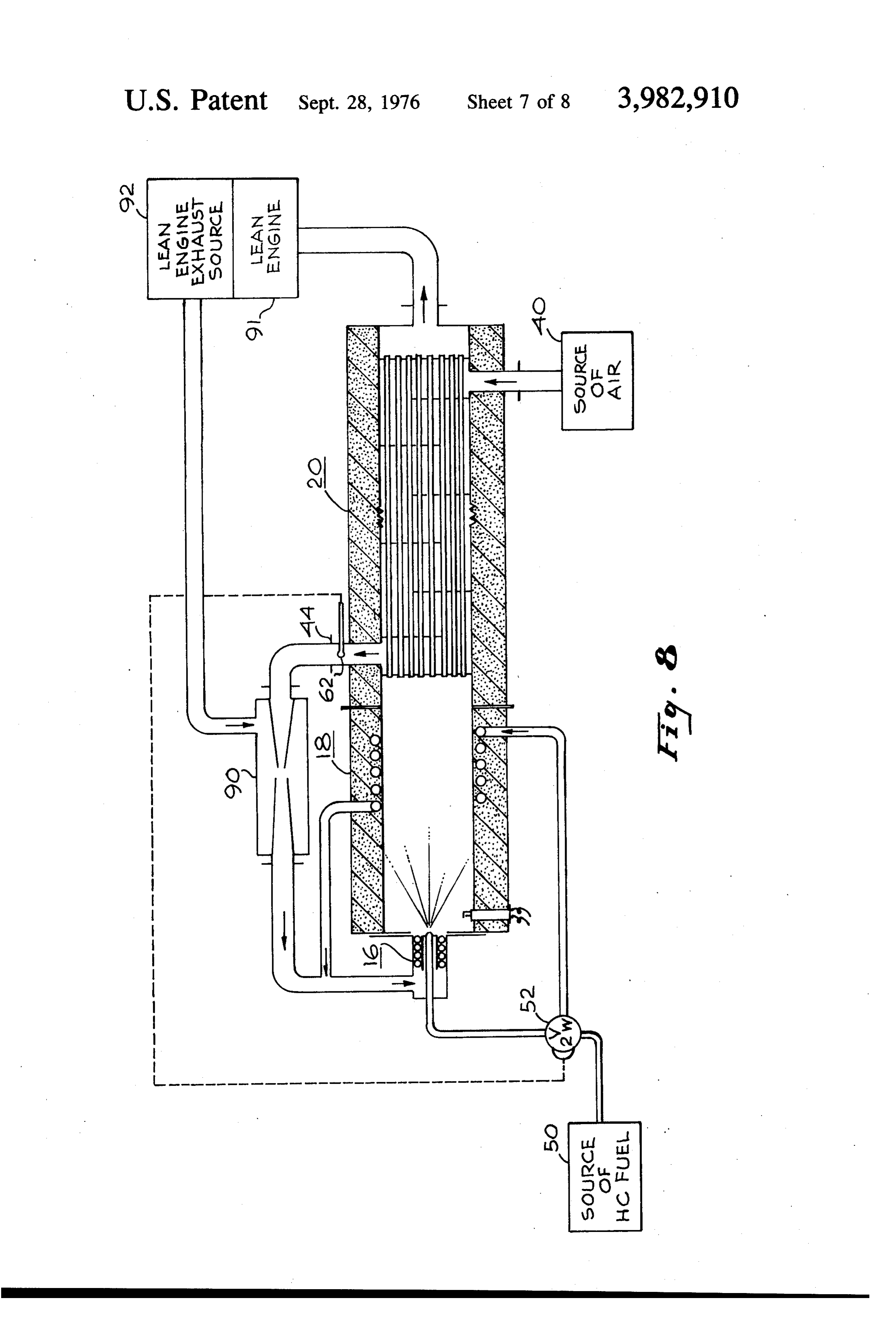
FIG. 8 is a cross sectional and schematic view of an
OBJECT AND SUMMARY OF THE INVENTION 50 embodiment of the invention which feeds back engine An object of this invention is to provide a hydrogen exhaust gas.
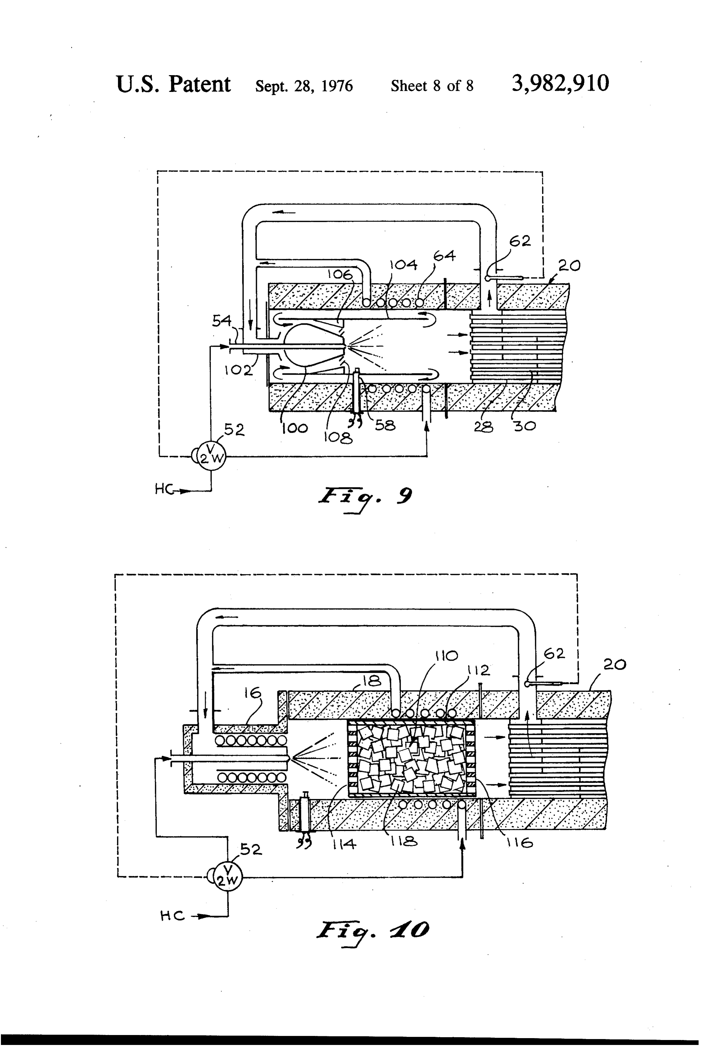
rich soot-free gas generator. FIG. 9 is a cross sectional view of an embodiment of Yet another object of this invention is the provision the invention illustrating the employment of a catalyst. of a novel and useful method and means for generating 55 DESCRIPTION OF THE PREFERRED a soot-free hydrogen-rich gas from liquid hydrocarbon EMBODIMENTS fuel.
Still another object of the invention is the provision FIG. 1 represents the theoretical yield of hydrogen of an improved construction for a hydrogen-rich gas which can be obtained from the adiabatic combustion generator. of mixtures of air, hydrocarbon, and water. JP-5 fuel Yet another object of this invention is the provision 60 has been used in these calculations, since its hydrogen of a portable hydrogen-rich gas generator suitable for to carbon ratio (1.92) is about the same as for Indolene use with an automobile internal combustion engine. (Federal test gasoline). Diagrams for other hydrocar The foregoing and other objects of the invention may bon fuels are very similar. It should be realized that in be achieved in an arrangement wherein air, which is to 65 actual practice the chemical kinetic rate of reaction be mixed with the fuel is preheated. The hydrocarbon may control the product formation. Chemical equilib fuel is vaporized and is then mixed with the preheated rium thus represents only a goal which may or may not air. Thereafter, the mixture is ignited and partial oxida be achievable. The hydrogen yield in FIG. 4 is ex tion is permitted. Further improvement is obtained by pressed as the mass of hydrogen produced per unit of
Page 11
mass of fuel, as a function of the air/fuel mass ratio and chamber to a collection space 32 leading to the exhaust for water/fuel mass ratios of 0.1 and 2, and is repre flange 34.
sented by the respective curves 10, 12 and 14. The A plurality of baffles, 36, 38, for example are spaced adiabatic flame temperature as a function of the same from one another and extend from opposite sides of the parameters is represented in FIG. 2 by curves respec inner wall 24 in a manner so that air, which is intro tively 10A, 12A and 14A. The curves in FIG. 3 show duced from a source of air 40, through an entrance flange 42, into the region of the heat exchanger, will the distribution of the various species as a function of the air/fuel ratio when no water is added. follow a zigzag path through the space between the As may be seen in FIGS. 1 and 3, for zero water O tubes 28, 30 until the air reaches an air exit flange 44, addition, the hydrogen yield increases from zero stoi which is provided at the opposite end from the air chiometry with decreasing air/fuel ratios until it entrance flange and the heat exchanger region. In this reaches a maximum at an air/fuel ratio of 5.15 (curve manner the air comes in contact with the tubes through 10), where soot formation starts. Production of soot which hot combustion gases pass. The baffles 36, 38, increases considerably at lower air/fuel ratios. The 5 provide for cross flow of the air across these tubes and addition of water does not greatly increase the hydro thus effectuate an effective heat transfer. An expansion gen yield, as may be seen from curves 2 and 14 in FIG. bellows 46 in the internal wall eliminates thermal stress 1. Strictly on this basis, the considerable complexity of therein as well as in the tubes. adding water does not seem warranted. However, the The air leaves the exit flange 44 and is directed into water addition does have a valuable function. It sup 20 from the burner 16. At startup, a liquid hydrocarbon fuel presses soot formation. For instance with a water-to a source 50, is pumped through a two way valve fuel ratio of 1, soot is only formed below an air/fuel 52, into the burner 16. The burner has a startup nozzle ratio of 3.9, compared to a value of 5.15 without water. 54, whichchamber emits a spray of liquid droplets into the com This soot suppression value of water addition is of im bustion 56 in the combustion section 18. portance when a spray of liquid droplets is being 25 ignited by a sparkplug in58,thewhich
The air/fuel mixture combustion chamber is is powered from a burned in the air. However this problem can be mini power source 60. A partial oxidation reaction then mized by vaporizing the liquid hydrocarbon and thor occurs and produces hydrogen-rich product combus oughly mixing it with the air before feeding the mixture tion gases which enter the tubes 28, 30, passing to an ignition zone. This process assures a uniform air through and exchanging heat with the incoming there air so to fuel ratio for all of the fuel and it is what is carried to that the product gas which is emitted has been cooled out by this invention. down.
FIGS. 1, 2 and 3 represent the conditions when the reaction has gone to completion, i.e. equilibrium condi theDuring start up, the air-fuel ratio is maintained above vaporized fuel normal design value and in a region, tions have been reached. In practice, the rate at which as shown by curve 10, in which a soot-free operation a reaction proceeds toward equilibrium may be so slow 35 occurs. There is a temperature sensor 62 in the air exit that equilibrium will not be obtained in a finite time flange, and when this sensor detects the fact that a period. However, the rate of reaction often increases preset temperature value has been exceeded by the exponentially with temperature, and this is what hap preheated air (a temperature above the liquid fuel pens with the partial oxidation of hydrocarbons. It has point temperature), it controls the two way valve 52dew to been found, that higher reaction temperatures result in 40 prevent further application of fuel to the start up nozzle a closer approach to equilibrium. Higher reaction tem in the burner, and instead supplies the fuel to a fuel peratures, i.e. flame temperatures, can be obtained by vaporization coil 64. Changes in the amount of fuel preheating the air. Thus in the thermal reactors de delivered to the burner and to the vaporizer are deter scribed subsequently, high air preheat is used to obtain mined by the sizes of the two way valve exit ports. The high hydrogen yields. Another way to speed up the rate 45 coil 64 is wound on the inner metal combustion shell or of a chemical reaction is to use a catalyst. This method inner wall 24, and is imbedded in the insulation 26. was used in the catalytic reactor described later, in The vaporized fuel leaves the coil exit 66, and there which high reaction rates and high hydrogen yields after is mixed with the heated airstream coming out of were obtained without the use of high temperatures. It the air exit flange 44. The premixed vaporized fuel/air . has been found that the theoretical equilibrium product 50 stream now passes through the burner 16 into the com composition is hardly affected by the higher tempera bustion chamber, where partial oxidation of the fuel ture. FIG. 4 shows three curves respectively, 10B, 12B takes place to produce a hydrogen-rich gas. It should and 14B for water/fuel mass ratio conditions such as be noted, that when the two way valve 52 is switched to are shown in FIG. 1, which show the change in equilib the vaporized fuel position, the air-to-fuel ratio is re rium temperature with increase in inlet temperature. 55 duced to the operating value for vaporized fuel. The effect of air preheat on the final equilibrium tem By way of illustration, and not to serve as a limitation perature is considerable. on the invention, when the air preheat temperature FIG. 5 is a cross sectional and diagrammatic view of reached 450 F the two way valve 52 was switched to an embodiment of this invention. It basically comprises feed fuel to the vaporization coil. In an embodiment of three parts. A burner section 16, a combustion section 60 the invention which was built the preheated air temper 18, and a heat exchanging section 20. The combustion ature was permitted to reach 1200 F, producing a chamber and heat exchange section together effec reaction temperature of 2400 F, producing a high tively constitute a hollow cylinder having an outer wall hydrogen-rich product gas yield. Air preheat tempera 22, an inner wall 24 spaced therefrom, and suitable ture may be determined, to a large extent, by the design insulation 26, such as cast ceramic, therebetween. The 65 of the heat exchanging section.
heat exchanging section 20 includes a plurality of hol The hot inner wall or cylinder 24, is structurally a low tubes, 28, 30, for example, which are spaced from floating item and it is supported by the thermal insula one another and which extend from the combustion tion such as the cast ceramic insulator, which sets up a
Page 12
S 6 considerable temperature gradient so that the outer The operation of the embodiment of the invention wall 22 is at a much lower temperature. The cold outer shown in FIG. 7 otherwise is the same as has been wall does seal the unit and provides structural strength. described for FIG. 6 and therefore will not be rede The unit is shut down by shutting off the hydrocarbon scribed here.
supply pump first, allowing the air to remain on for a FIG. 8 illustrates an embodiment of the invention few seconds, thus purging the unit of hydrogen. This which mixes lean engine exhaust gas with the preheated discourages a system of residual hydrogen-rich gases air, instead of the product gas. The exhaust gas stream that may represent a potential safety hazard. There is from an internal combustion engine, which may be insufficient mixing between the air and the hydrogen operated at equivalent ratios of the order of 0.5, con rich gas during this operation to have any appreciable 10 tains on the order of 10% by volume of oxygen, has a heat release in the heat exchanger or in the line be high water content (6 volume percent), and a high yond. temperature (at least 1000 F). Consequently, this If it is desired to operate the unit at an extremely low exhaust gas stream can replace a fraction of the genera air/fuel ratio, where soot formation becomes a prob 5 tor air requirements and it also has advantageous prop lem, water addition can be used for soot suppression. erties of high water content and high preheat. How Water may be added in with the fuel at the entrance to ever, care must be taken in how much of the exhaust the fuel vaporization coil. This applies to steady state gas is used since below an oxygen content of approxi operation. Start up would be accomplished in the man mately 13 volume percent, gasoline is no longer flam ner described without water. mable. This minimum required oxygen level decreases FIG. 6 is an enlarged and detailed view, in cross 20 with increasing temperature.
section of the burner 16. The start up nozzle 54 is An internal combustion engine of the type described represented by the dashed central line. When the two in the Rupe application, Ser. No. 387,342, filed Aug. way valve is operated to apply the hydrocarbon fuel to 10, 1973, previously mentioned herein, illustrates the the vaporizing coil, then the premixed feed gases are type of engine whose exhaust products may be used. directed into two helical tubes respectively 70, 72 and 25 This is by way of illustration but not by way of a limita the two passages between the tubes, and are thereafter tion of a suitable internal combustion engine. directed into the combustion chamber as a strongly It will be noted that the embodiment of the invention outwardly rotating annulus of gas represented by four which streams that merge as they come out, two of which are 30 the oneisshown shown in FIG. 8 is substantially identical with shown as 74,76. The length of the flame that exists can an aspirator 90,inisFIG. 7, as well as in FIG. 6 except that coupled to receive the preheated air be tailored by changing the angle of the helical path in from the exhaust flange 44, as previously described. the burner. A steeper angle results in a longer flame. The other input into the aspirator There is a tradeoff between the length of flame and the the lean engine exhaust source of90gases, is received from 92. The ex fact that the longer flame keeps the hottest part of the haust gas is mixed with the preheated air and the aspi flame in the center and off the walls of the combustion 35
rator output is then mixed with the vaporized fuel, and
FIG. 7 is a cross sectional and schematic view of an thereafter is applied to the burner. The operation of the embodiment of the invention shown in FIG. 8 is other embodiment of the invention which utilizes product gas wise the same as was previously described. The unit for recirculation. The advantage of the use of product 40 depicted in FIG. 8 can be operated at a lower air/fuel gas is that this dilutes the oxygen content of the air and ratio without soot formation, than the basic unit shown modifies the reaction mechanism. The hydrogen in the in FIG.S.
producut gas also modifies the combustion reactions FIG. 9 shows an embodiment of the invention, in and increases flame stability. The combination of these cross section, wherein the product gas which is fed factors suppresses carbon formation. The overall result 45 is that the unit depicted in FIG. 7, utilizing product gas back to be mixed with the incoming air/fuel mixture, is recirculation, can be operated at a lower air/fuel ratio derived internally without leading the product gas out of the burner. This reduces the amount of air pressure without soot formation than the unit shown in FIG. 5. A lower air/fuel ratio represents a more efficient operat required to obtain a certain amount of recirculation. ing condition. It should be noted that product gas recir 50 The unit is again started by introducing liquid hydro culation does not add any net energy to the generator carbon through a spray nozzle 54, which extends fur as the product gas stream is at or below the adiabatic ther into the combustion chamber than in the previous flame temperature. embodiments of the invention. It extends through a The hydrogen generator unit shown in FIG. 7 is iden pear shaped body of revolution 100. Incoming pre tical with the one shown in FIG. 6 except that a gas-gas 55 heated air is led by a suitable passageway 102, to the aspirator 80 has been added. Also, an exit port 82 has base of the pear shaped figure of revolution 100 over been provided from the combustion zone, to permit the which it passes. A freestanding cylinder 104 supported hydrogen product gas to flow to the aspirator 80. The from the walls by thin spokes, (not shown), is posi preheated air flows from the heat exchanger exit flange tioned within the combustion chamber. The walls of 44, into a Venturinozzle 84, whose converging sections the cylinder, adjacent the surface of the figure of revo produce a high air velocity at the terminal end thereof. 60 lution, support inwardly flaring walls, 106, spaced from The resulting high air velocity causes a low pressure the walls of the figure of revolution to define a passage region adjacent the Venturi nozzle throat, which aspi way therewith, and form a Venturi-like device. A set of rates the product gas from the product gas exit port 82 vortex vanes 108 is positioned at the exit from this and causes it to be mixed in the nozzle 88, with the air passageway to impart a vortex motion to the air flow. stream. The mixture of air and product gas exits from 65 Initially the spray of liquid fuel droplets is ignited, as the diverging sections of the nozzle 88 and thereafter is before, by the spark plug 58 and hot combustion gases mixed with the vaporized fuel. The resulting stream leave the combustion chamber through the tubes 28, enters the burner at the burner entrance flange. 30,
Page 13
The freestanding cylinder 104, provides an annular sure was 1.0 psig, and the generator thermal efficiency space between it and the walls of the combustion cham was 0.785. The output can be increased by increasing ber through which product gas is recycled back to the the input and an H, output flow rate as high as 2 pounds low pressure throat region of the Venturi defined by per hour was thus obtained. The dimensions of the the cylinder and the surface of the figure of revolution. generator that was built and performed as above are 15 As before, when the air temperature sensed by the inches long and 6 inches in diameter, which includes sensor 62 reaches a preset value the two way valve 52 the heat exchanger.
is switched to transfer the liquid fuel to the vaporiza Any hydrocarbon that can be vaporized and mixed tion coil 64, and now a mixture of vaporized fuel and with air without decomposition may be usued with the hot air enters the combustion chamber to be converted 10 embodiment of the invention. It is obvious that the into product gas, a portion of which is recycled back higher the hydrogen to carbon atomic ratio of the fuel and mixed with the incoming fuel vapor?air mixture to that is used, the higher the hydrogen yield will be. be thereafter introduced into the combustion chamber The catalytic hydrogen generator, in accordance cavity where the partial oxidation reaction takes place. with this invention has the following advantages over Again, the main advantage of the unit shown in FIG. 9 5 the previous thermal units.
over the standard unit of FIG. 5 is operation at lower 1. There is a higher hydrogen yield. air/fuel ratios without soot formation. 2. There is no tendency to form soot, even at low FIG. 10 is a cross sectional view of another and pre ferred embodiment of the invention. The hydrogen 20 air/fuel 3. The ratios. The product is absolutely soot free.
generator has lower operating temperatures, generator structure is the same as has been described allowing the use of less expensive construction materi for FIG. 5, with the difference that a catalyst is em als.
ployed which produces several advantages, such as higher hydrogen yield and no tendency to form soot the4.heat Lower air preheat requirements reduce the size of even at very low air/fuel ratios. Also, much lower oper 25 compact exchanger design of that is required. As a result, a more the hydrogen generator is achiev ating temperatures (1800 F) are permitted whereby able making it suitable for automobile use. lower air preheat requirements (450 F) permit a There has accordingly been described herein, a novel Smaller heat exchanger.
Adjacent the region where combustion takes place, useful and improved hydrogen generator. We claim:
during startup, there is placed a catalytic bed 110 com 1. A hydrogen generator comprising prising a cylinder 112, which has a perforated top wall 30 means for defining a source of liquid hydrocarbon, 114 and a perforated bottom wall 116 to permit the hot means for defining a source of air, gases to flow therethrough into the heat exchange sec means establishing a partial oxidation region, tion 20. The catalyst bed contains particles 118, of a means to which said means defining a source of liquid partial oxidation catalyst such as nickel deposited on a carbon is connected for producing a spray of drop substrate, such as aluminum, which serves to speed up 35 lets from said liquid hydrocarbon source and in the partial oxidation reaction of the hydrocarbon with air to yield a hydrogen-rich gas. It has also been found jecting said spray into said partial oxidation region, that the nickel catalyst has a strong soot suppressing means for injecting air from said means defining a action. Other partial oxidation catalysts such as palla source of air into said partial oxidation region to be dium, platinum or silver oxide may also be used for the 40 mixed with said spray, reaction of hydrocarbon and air. In principle any of the means to which said partial oxidation region is con known oxidation type catalysts for the reaction of oxy nected for igniting said air-spray mixture to permit gen and a hydrocarbon can be used. The particular production of hot hydrogen-rich product gases, form of catalysts used here fall in the category of steam means to which said means defining a source of air is reforming catalysts, however in this invention the reac 45 connected for preheating air from said source prior tion is of oxygen and a hydrocarbon rather than of to its injection into said partial oxidation region steam and a hydrocarbon. with said hot hydrogen-rich product gases, It has been noted that upon start up, the generator means coupled to said means for preheating air for with a catalyst bed operates in a similar manner to the determining when the temperature of said pre generators previously described. That is, there is a SO heated air exceeds a predetermined value and pro burning of the vaporized fuel in the vicinity of the ducing a signal, burner. As the catalyst bed heats up towards the oper means coupled to said means defining a source of ating temperature (beyond 900 F), the flame gradually liquid hydrocarbon for vaporizing said liquid hy moves into the catalyst bed. When a steady state tem drocarbon, perature of 1800° F is reached, there is no visible flame 55 valve means responsive to said signal for terminating present. The partial oxidation process takes place en the application of liquid hydrocarbon from said tirely on the surfaces of the catalyst. The catalyst may source to said means for producing a spray of drop be in the form of pellets or in the form of a monolythic lets and for directing it instead to said means for Structure. vaporizing liquid hydrocarbon to produce vapor By way of illustration, and not by way of a limitation 60 ized hydrocarbon, upon the invention, an embodiment of the invention means for directing said vaporized hydrocarbon to was built and operated with an input air flow rate of said means for injecting air to be mixed with said 45.6 pounds per hour, and a fuel flow of 8.9 pounds per preheated air and injected therewith into said par hour. The air/fuel ratio was 5.15 with an equivalence tial oxidation regions, and ratio of 2.83. Generator pressure was 1.4 psig. The 65 means for removing hydrogen-rich product gases catalyst temperature was measured at 1774 F. from said partial oxidation region. With the above input 1.06 pounds per hour of H was 2. A hydrogen generator as recited in claim 1 obtained, along with other components. The exit pres wherein there is included
Page 14
means for mixing some of said hydrogen-rich product receive hydrogen-rich gases from said burner sec gases from said partial oxidation region with said tion, and preheated air and said vaporized hydrocarbon. means coupling said aspirator means output to said 3. A hydrogen generator as recited in claim 1 burner means.
wherein there is included catalyst means positioned 5 9. A hydrogen generator as recited in claim 5 within said means establishing a partial oxidation re gion for partially oxidizing the vaporized fuel on the wherein there is included catalyst means placed in said burner section having surfaces over which gases in said surfaces of said catalyst means. burner section pass to said preheat section to be gener 4. A hydrogen-rich generator as recited in claim 3 ated into hot hydrogen-rich product gases. wherein said catalyst means is one of a group consisting 10 10. A hydrogen generator as recited in claim 9 of nickel, palladium, platinum and silver oxide. wherein said catalyst means is one of a group consisting 5. A hydrogen generator comprising walls defining a of nickel, palladium, platinum and silver oxide. chamber, said chamber having a separate preheating 11. A hydrogen generator as recited in claim 5, section and a burner section, wherein said vaporizing means comprises tubing means defining a source of air, 5 wrapped around the walls defining said burner section. means for passing air from said means defining a 12. A hydrogen generator as recited in claim 5 source of air through said preheating section to be wherein said burner means includes preheated, a pear shaped body positioned with its narrower end means defining a source of liquid hydrocarbon, burner means for injecting preheated air from said 20 adjacent other end one end of said burner section and its extending into said burner section, preheating section and a spray of liquid hydrocar central passageway means passing through the center bon from said means defining a source of liquid of said pear shaped body for injecting said liquid hydrocarbon into said burner section, hydrocarbon spray into said burner section, vaporizing means for forming a vaporized hydrocar first passageway means for guiding said preheated air bon from said liquid hydrocarbon, 25 over said pear shaped body surface and into said means coupling said means defining a source of liq burner section, including uid hydrocarbon to said burner means including a a hollow cylinder within said burner section, said valve means having a first position for directing hollow cylinder enclosing said pear shapped body said hydrocarbon fuel to said burner means and a and extending into said burner section, and second position for directing said hydrocarbon to 30 means extending from the inside walls of said hollow said vaporizing means, cylinder toward the surface of said pear shaped temperature sensing means for sensing the tempera body to form said first passageway means there ture of said preheated air and switching said valve with, means to its second position when it senses a tem perature in excess of a predetermined level, 35 said hollow cylinder outside walls being spaced from means for applying said vaporized hydrocarbon and said chamber walls to define a second passageway said preheated air to said burner means to be mixed therewith for returning some of said hydrogen-rich thereby and injected into said burner section, product gases to said first passageway to be mixed igniter means adjacent the burner means in said com with said air and vaporized hydrocarbon fuel. bustion section for igniting the air-hydrocarbon 40 13. A hydrogen generator as recited in claim 5 output from said burner means whereby a partial wherein said burner means includes central passageway oxidation of said hydrocarbon can occur with the means for injecting liquid hydrocarbon fuel spray, and spiral passageway means surrounding said central production of hot hydrogen-rich product gases, and passageway means for injecting air into said burner means for passing said hot hydrogen-rich product 45 section when said valve means is in its first position gases from said combustion section through said and a mixture of air and vaporized liquid hydrocar preheating section for preheating said air. bon when said valve means is in its second position. 6. A hydrogen generator as recited in claim 5 14. The method of producing hydrogen-rich product wherein said valve means includes a first exit port in the gases from liquid hydrocarbon comprising path of hydrocarbon fuel through said valve means to 50 providing a stream of air, said burner means and a second exit port in the path of generating a spray of a first portion of said liquid said fuel through said valve means to said vaporizer hydrocarbon, means, mixing a spray of said liquid hydrocarbon with said said second exit port opening being greater than said stream of air to produce a first mixture, first exit port opening. 55 partially oxidizing said first mixture to produce hy 7. A hydrogen generator as recited in claim 5 drogen-rich hot product gases, wherein there is included means to mix a portion of heating said stream of air prior to mixing with said said hydrogen-rich product gases from said partial oxi liquid hydrocarbon spray by indirect heat exchange dation region with said mixture of vaporized hydrocar with the hydrogen-rich hot product gases to pro bon and air. 60 duce heated air, 8. A hydrogen generator as recited in claim 7 measuring the temperature of said heated air and wherein said means to mix a portion of said hydrogen producing a signal when it exceeds the dewpoint of rich product gases with said mixture of vaporized liquidsaid liquid hydrocarbon, hydrocarbon and air includes vaporizing a second portion of said liquid hydrocar aspirator means having two inputs and an output, 65 bon to produce a vaporized hydrocarbon, and means coupling one of said aspirator means inputs to mixing said vaporized hydrocarbon with said heated receive preheated air from said preheater section air in place of said spray in response to said signal, and the other of said aspirator means inputs to and
Page 15
partially oxidizing said mixture of vaporized hydro step of partially oxidizing said first mixture includes the carbon with said heated air instead of said first step of mixture to produce hydrogen-rich product gases. igniting said mixture in a confined space and thereaf 15. The method as recited in claim 14 wherein there ter passing over the surfaces of a catalyst. is included the step of mixing some of said hydrogen 17. The method as recited in claim 16 wherein said rich product gases with said mixture of vaporized hy catalyst is one of the group consisting of nickel, plati drocarbon and preheated air. num and silver oxide.
16. The method as recited in claim 14 wherein said
Provenance
- Collection
- Cited prior art
- Original PDF
- patentimages.storage.googleapis.com →
- Filed
- 1974-07-10
- Pages
- 15
- Method
- pdftotext (the PDF's own text layer) + pdftoppm 300dpi page scans
- Source
- Google Patents bibliographic record
- Granted
- 1976-09-28
- Inventors
- John Houseman; Donald J. Cerini; National Aeronautics and Space Administration NASA
- Transcribed from
- patentimages.storage.googleapis.com →