patent · US4520764
Starter for an alcohol engine
4 June 1985
Page 1 — bibliographic record
United States Patent (19) 11 Patent Number: 4,520,764 Ozawa et al. 45 Date of Patent: Jun. 4, 1985 54 STARTER FOR AN ALCOHOL ENGINE 56) References Cited 75) Inventors: Masuo Ozawa, Yokohama; Toshio U.S. PATENT DOCUMENTS Hirota, Yokosuka, both of Japan 3,933,130 1/1976 Csicsery .................................. 123/3 3,963,000 6/1976 Kosaka et al. .......................... 123/3 73) Assignee: Nissan Motor Co., Ltd., Yokohama, 3,986,350 10/1976 Schmidt ........ ... 60/274 Japan 4,226,213 10/1980 Bernauer ............................ 123/3 X 4,230,072 10/1980 Noguchi et al. .................... 123/3 X 21 Appl. No.: 205,448 OTHER PUBLICATIONS 22) PCT Filed: Dec. 27, 1979 Combustion and Emission of Gaseous Fuel from Re formed Methanol in Automotive Engine, Tokuichi 86 PCT No.: PCT/JP79/00329 Inagaki et al. pp. 1-13.
S 371 Date: Aug. 28, 1980 Primary Examiner-William A. Cuchlinski, Jr. Attorney, Agent, or Firm-Schwartz, Jeffery, Schwaab,
S 102(e) Date: Aug. 27, 1980 Mack, Blumenthal & Evans 87). PCT Pub. No.: WO80/01398 (57) ABSTRACT PCT Pub. Date: Jul. 10, 1980 A starter for an alcohol engine, which incorporates a reformer containing catalyst heated by exhaust gas to (30) Foreign Application Priority Data thereby react fuel alcoholso as to produce reformed gas containing hydrogen and carbon monoxide as main
Dec. 28, 1978 (JP) Japan ................................ 53-16047 components and to store the produced gas in the re former. The reformed gas is supplied to a carburetor of 51 Int. Cl. ...................... F02M 27/02; FO2M 31/08 the engine at its starting time to mix it with the main fuel 52 U.S. Cl. ................................... 123/3; 123/180 R; alcohol to supply the mixture to a combustion chamber 123/DIG. 12; 123/180 E so as to facilitate easy ignition.
123/180 E, 576, DIG. 12 8 Claims, 2 Drawing Figures
Page 2
Drawing sheet — no readable text.
Page 3
Drawing sheet — no readable text.
Page 4
STARTER FOR AN ALCOHOL ENGINE
10 in such a manner that these components are supplied with heat from the exhaust gas. This passageway 14 is
TECHNICAL FIELD
thereafter connected at relatively downstream position of the exhaust tube 5 via an intervention of an electro
The present invention relates to a starter for an en magnetic valve 16. The aforementioned reformer 12 has gine using alcohol, such as methanol, ethanol or the a catalyst bed which is filled up with a reforming cata like, as its fuel. lyst at the inside.
BACKGROUND ART 17 and 18 are sensors for detecting the pressure and the temperature, respectively, in the reformer 12, 19 is a
In the recent years, alcohol has been considered as a O sensor for exhaust gas temperature, and 20 is a control prospective substitute for gasoline as fuel for automo unit operating by signals sent from these sensors 17, 18 tive vehicles. However, alcohol has a higher boiling and 19 and a signal sent from a starter switch 21 and for point than gasoline, as for example 64.5° C. in methanol. controlling the electromagnetic valves 9, 11, 13, 15 and Consequently, a problem has developed in starting an 16.
alcohol fueled engine. 5
Accordingly, several proposals for solving the start valves This control unit 20 acts to open the electromagnetic ing problems have been suggested. One such proposal is former 9,12 11, 15 and 16 when the pressure in the re detected by the pressure sensor 17 is lower to store gasoline as an auxiliary fuel besides the alcohol than a previously settled value (this settled value is and to use the gasoline at the starting time and to switch 20 compensated to alcohol after a certain warm up driving time i.e. from the temperature sensor 18)detecting by a temperature and also signal sent when the when the temperature rises up to an extent sufficient for exhaust gas temperature detected by an exhaust gas easy evaporation of the alcohol. Another proposal is to temperature sensor 19 is higher than a previously settled evaporate the alcohol by warming up the manifold by an electric heating wire at the starting time. value and it also acts to open the electromagnetic valve However, the former proposal has the disadvantage 25 13 when the starter switch 21 is turned on. that the auxiliary fuel should be carried separately from The operation of the device of the present invention the gasoline and the latter proposal has the disadvan will be explained hereinafter.
tage that a longer time is required for starting. During the operation of the engine, if the pressure of
DISCLOSURE OF INVENTION
the reformed gas in the reformer 12, which has been 30 produced and stored therein in a manner described
In view of the aforementioned situation, the present hereinafter, is lower than the previously settled value, invention has as its object to provide a starter for an namely if the residual amount of the reformed gas is not alcohol engine which is able to start an alcohol engine sufficient, the electromagnetic valves 9, 11, 15 and 16 as easily as a conventional gasoline engine. are opened provided that the exhaust gas temperature is In accordance with the above object, in the present 35 higher than the previously settled value, namely when invention, a part of the fuel alcohol is reformed into a the exhaust gas temperature is high enough for the gaseous fuel containing hydrogen and carbon monoxide formation of the reformed gas, then the alcohol deliv as the main components during operation of the engine ered from the fuel tank 6 to the reformer 12 via the and is stored and thus stored gaseous fuel is supplied to evaporator 10 reacts on the catalyst bed (in case of the engine when starting the engine so as to obtain an 40 methanol; CH3OH-2H2--CO) and the reformed gas easy ignition thereof. containing hydrogen and carbon monoxide as the main The invention will now be explained by referring to components is produced. Herein, this reaction is an the drawings. endothermic reaction and the reaction heat is obtained
from the exhaust gas passing through the passageway
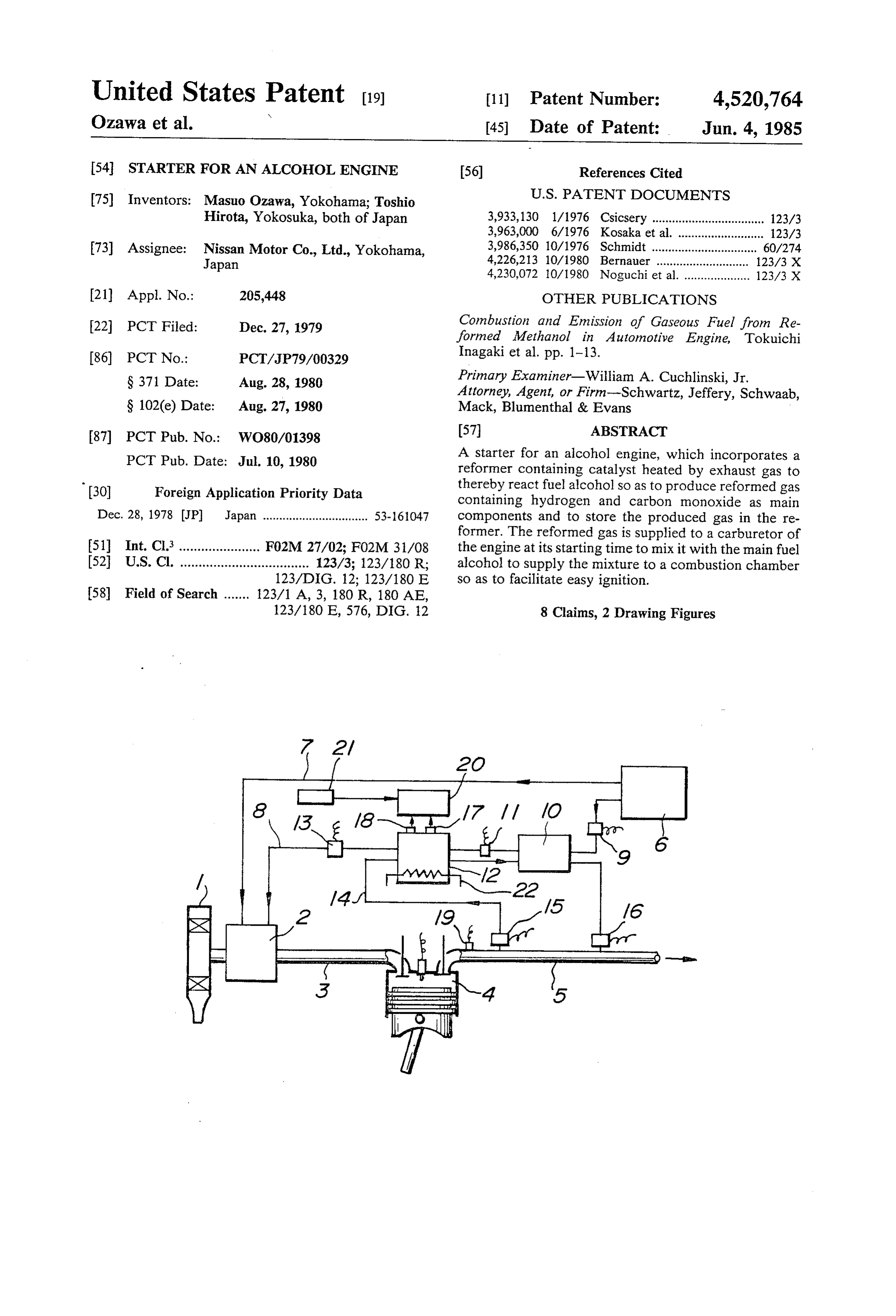
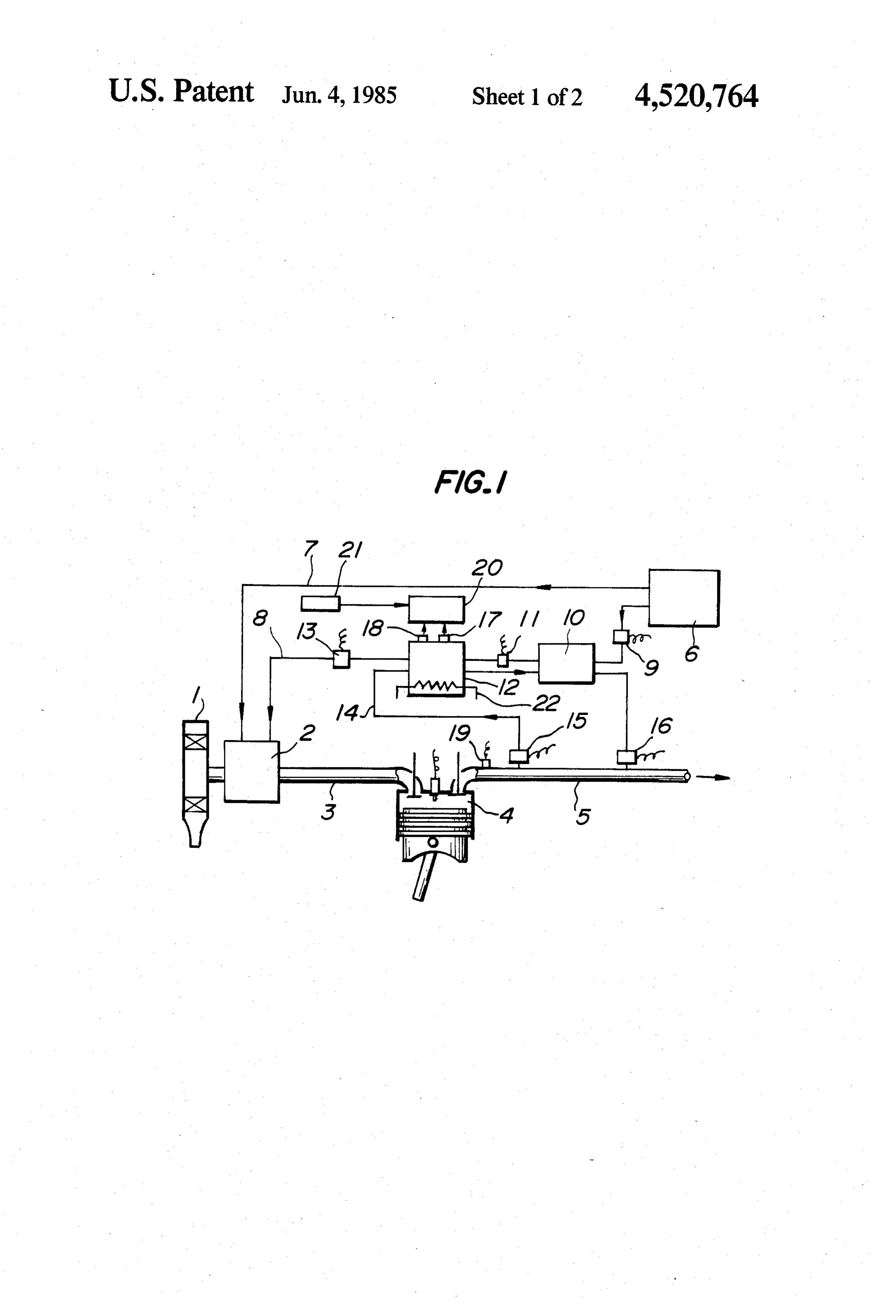
FIG. 1 is a diagrammatic illustration showing one forming 14. The produced reformed gas is adsorbed in the re embodiment of the present invention; and catalyst in the reformer 12 since the electro magnetic
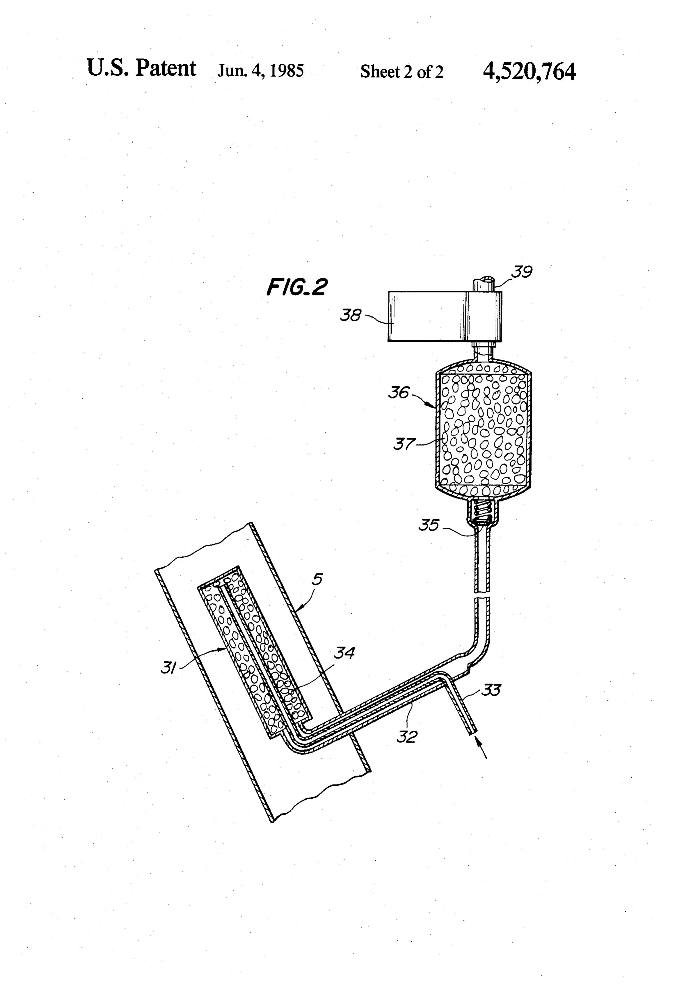
FIG. 2 is a cross-sectional view showing an essential reformer 12 valve 13 is then closed. If the pressure in the part of a modified embodiment thereof. rises by this, the electromagnetic valves 9, 50 11, 15, and 16 are closed again to discontinue further
BEST MODE OF CARRYING OUT THE production of the reformed gas and the already pro INVENTION duced reformed gas remains stored in the reformer 12. In FIG. 1, 1 is an air cleaner, 2 is a carburetor, 3 is an At restarting of the engine after it had been stopped, intake tube, 4 is a combustion chamber of the engine tion, the starter switch 21 is operated to be in the ON condi body, 5 is an exhaust tube, and 6 is a fuel tank for storing 55 and by this the electromagnetic valve 13 is opened, the fuel alcohol. The alcohol is supplied to the carbure and as has been explained in the foregoing, the stored tor 2 via a main fuel passageway 7. reformed gas in the reformer 12 being rich in hydrogen As the starter according to the present invention, a and carbon monoxide is supplied to the carburetor 2 and passageway 8 leading from the fuel tank 6 to the carbu this reformed gas is mixed with the air and with alcohol retor 2 is provided separately from the main fuel pas 60 fed through the main fuel passageway 7 in the carbure sageway 7. In this passageway 8, an electromagnetic tor 2 and is fed to the combustion chamber 4. This valve 9, an evaporator 10, an electromagnetic valve 11, reformed gas has very excellent combustion character a reformer 12, and an electromagnetic valve 13 are istics of a high combustion speed, and of small ignition inserted in the above order starting from the fuel tank energy. Accordingly, the engine can be started very side. A passageway 14 branched from the exhaust tube 65 easily.
5 at comparatively upstream point thereof is provided Once the engine is started, it can be driven only by via an insertion of an electromagnetic valve 15. Passage alcohol so that the electromagnetic valve 13 is closed way 14 extends to the reformer 12 and to the evaporator again simultaneously with the turn off of the starter
Page 5
switch 21 and the supply of the reformed gas is discon carburetor of the engine through the gas outlet 39 and tinued. via a tubing system not shown in the drawing. After the supply of the reformed gas, if there still By providing the reformer and the gas storage device remains a sufficient reformed gas in the reformer 12, the separately as explained above, the following advantage formation of the reformed gas is not effected even if the 5 can be obtained. Firstly, since the reformer is exposed exhaust gas temperature is high, however, if there is not to the exhaust gas of the engine, it may be heated up to much reformed gas remaining therein, the electromag 300 to 700 C. during operation of the engine so that if netic valves 9, 11, 15 and 16 are kept opened at rising of the gas is stored in such a high temperature reformer, it the exhaust gas temperature and the reformed gas is is inevitable that the amount of storage decreases. How produced and stored in the same manner as has been 10 ever, if the gas storage device is provided separately, explained in the foregoing to prepare for the next start the amount of storage can substantially be increased 1ng. since the gas can be stored at a lower temperature. In case sufficient heat for the reformation reaction is Secondly, if the gas is stored in the reformer, the tem not obtained from the heat of the exhaust gas, an elec perature variation between the operation of the engine tric heating wire 22 is embedded in the reformer 12 and 15 and non-operation of the same after stopping is consid an electric current is supplied substantially synchro erably large so that the gas pressure decreases at low nized with the opening of the electromagnetic valves 9, temperature after the stopping of the engine so that a 11, 15 and 16 and the necessary heat for the reformation sufficient amount required for the starting may not be reaction may be produced for a part or all by this elec supplied. However, the pressure of the storage gas is tric heat. 20 not so lowered when the gas is stored at lower tempera Furthermore, the reformer 12 may be one incorporat ture from the beginning by arranging the gas storage ing evaporator 10 and in this case the electromagnetic device separately. Thirdly, the reformer can be made valve 11 can be dispensed with. small and it can be arranged in the exhaust gas pipe so FIG. 2 shows an embodiment in which the reformer that it is possible that the recirculation efficiency of the for reforming alcohol into gas and a storage device for 25 heat of the exhaust gas can be increased. storing the reformed gas are provided separately. The necessary amount of the reformed gas required Namely, a cylindrical shaped reformer 31 is arranged for one starting is very small and it is about l l in an in the exhaust gas pipe 5 and a cooling tube 32 penetrat engine having displacement of 2 l. Therefore, if we ing the exhaust gas pipe 5 and connected at one end of intend to store 3 l of gas for considering some more the reformer 31 is arranged outside the exhaust gas pipe 30 spare amount, the size of the storage device filled with 5. A supply conduit 33 of alcohol is introduced in the adosrbing member may be in an order of about 40 mm cooling tube 32 at middle point thereof and extended in the diameter and 80 mm in the length. The size of the coaxially therein and also coaxially in the reformer 31 to reformer may be about 25 mm in the diameter and 60 form double tube construction and an end thereof is mm in the length and it may easily be accommodated in opened adjacent another end of the reformer 31. Inside 35 the exhaust gas tube.
the reformer 31, the reforming catalyst is filled up. INDUSTRIAL APPLICABILITY The aforementioned cooling tube 32 is connected via a non-return valve 35 to a lower end portion of a gas As has been explained in the foregoing, according to storage device 36 formed cylindrically, which is filled the present invention, there is no need to mount an up with adsorbing member 37 such as activated carbon, 40 auxiliary fuel for starting besides the fuel alcohol and alumina, metal hydride or the like. An upper end of the the reformed alcohol gas is excellent in the combustion gas storage device 36, a normally closing valve 38 (act characteristics such as small ignition energy so that ing in the same manner with the aforementioned elec starting is very easy. Therefore the present invention tromagnetic valve 13) is mounted. 39 is a gas outlet. contributes in saving the fuel petroleum resources. The operation is now explained. During operation of 45 We claim:
the engine, alcohol is supplied via the alcohol supply 1. In combination, an alcohol engine which operates conduit 33 into the reformer 31 and is evaporated in the exclusively on alcohol fuel, a source of alcohol fuel conduit 33 by a heat exchange with the reformed gas connected to said engine, and a starter for said engine, passing through the cooling tube 32 for instance, and said starter comprising:
this alcohol is reformed into gas such as hydrogen and 50 means connected to said fuel source for receiving carbon monoxide or the like in the reformer 31 by the alcohol fuel from said fuel source and reforming a reforming catalyst 34 while taking the heat of the ex portion of said alcohol fuel during operation of said haust gas flowing through the exhaust tube 5. The re engine into gaseous fuel containing hydrogen and formed gas passes through the cooling tube 32 and is carbon monoxide as its main components, compris cooled by the heat exchange with the alcohol flowing 55 ing reforming means for producing said gaseous through the supply conduit 33 prior to its reaction and fuel, and storage means for storing said gaseous enters into the gas storage device 36 via the non-return fuel, and wherein said reforming means is posi valve 35 and stored therein by adsorption of the adsorb tioned to receive heat from an exhaust pipe, and ing member 37. The gas storage device 36 may be a said storage means is located in a position remote mere hollow bomb without the adsorbing member 37 60 from said engine and said exhaust pipe so as not to but the storage efficiency can be much improved by be affected by heat from said engine or said exhaust filling up the adsorbing member 37. pipe; and
After stopping the engine, even if the pressure in the means for supplying said gaseous fuel to said engine reformer 31 decreases, the reformed gas remains stored from said storage means only during starting peri in the storage device 36 since the non-return valve 35 is 65 ods of said engine.
provided at entrance of the storage device 36. At start 2. The combination as set forth in claim 1, wherein ing of the engine, the control valve 38 is opened and the said storage means contains an adsorbing material for gas stored in the gas storage device 36 is supplied to the adsorbing said gaseous fuel.
Page 6
3. The combination as set forth in claim 1, wherein a control unit for controlling supply of the fuel alco said combination includes an engine starting switch, and hol into the reformer through the evaporator by said supplying means is connected to said switch and detecting temperature and pressure of the gaseous responsive to actuation of said switch for supplying said fuel in the reformer and controlling feed of the gaseous fuel to said engine. 5 reformed gaseous fuel.
4. The combination as set forth in claim 3, wherein 6. A starter for an alcohol engine as claimed in claim said reforming means is located within said exhaust 5, wherein the evaporator and the reformer are built in pipe. a unitary container.
5. A starter for an alcohol engine using alcohol exclu 7. A starter for an alcohol engine as claimed in claim sively as its fuel, comprising in combination: 10 5 or 6, wherein the reformer contains said adsorbing an evaporator for evaporating said fuel alcohol into a member to act as a storage device for storing the re gaseous phase; formed gaseous fuel.
a reformer for reforming the evaporated fuel alcohol 8. A starter for an alcohol engine as claimed in claim into gaseous fuel, which fuel contains hydrogen 5 and further including electric heating means for heat and carbon monoxide, said reformer containing a 5 ing said catalyst, and wherein the control unit supplies reforming catalyst as the main reforming element; an electric current to said heating means to heat the an adsorbing member for storing the generated re catalyst to make it active.
formed gaseous fuel; and sk k sk sk ck
Provenance
- Collection
- Cited prior art
- Original PDF
- patentimages.storage.googleapis.com →
- Filed
- 1979-12-27
- Pages
- 6
- Method
- pdftotext (the PDF's own text layer) + pdftoppm 300dpi page scans
- Source
- Google Patents bibliographic record
- Granted
- 1985-06-04
- Inventors
- Masuo Ozawa; Toshio Hirota; Nissan Motor Co Ltd
- Transcribed from
- patentimages.storage.googleapis.com →