patent · US3967589
Energy generating system
6 July 1976
Page 1 — bibliographic record
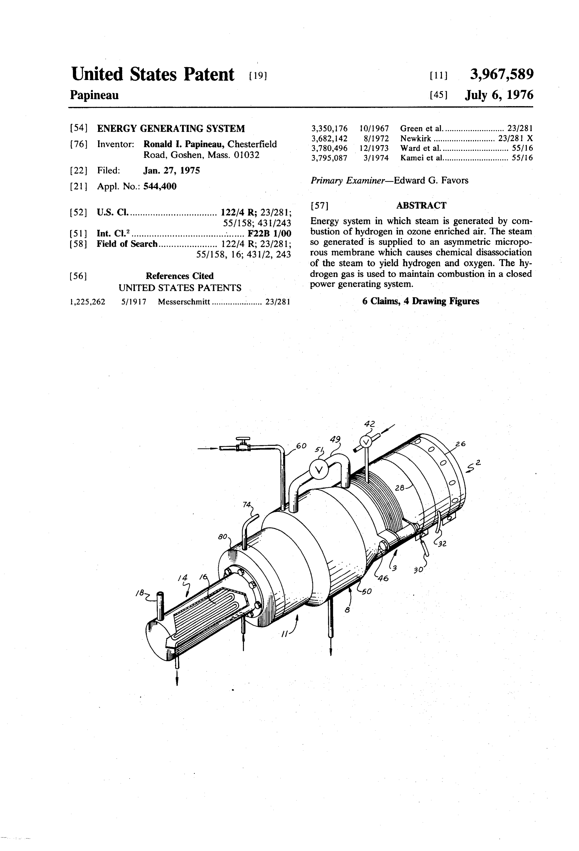
United States Patent (19) 11, 3,967,589 Papineau (45) July 6, 1976 (54) ENERGY GENERATING SYSTEM 3,350,176 10/1967 Green et al........................... 23/281 3,682, 142 8/1972 Newkirk............. ... 23/281 X 76) Inventor: Ronald I. Papineau, Chesterfield 3,780,496 12/1973 Ward et al.............................. 55/16 Road, Goshen, Mass. 01032 3,795,087 3/1974 Kamei et al............................. 55/16
21 Appl. No.: 544,400 Primary Examiner-Edward G. Favors
52) U.S. Cl. .................................. 122/4 R; 23/281;
55/158; 4311243 Energy system in which steam is generated by com (51) Int. Cl”...................................... . . . . . . F22B 1/00 bustion of hydrogen in ozone enriched air. The steam (58) Field of Search....................... 122/4 R; 23/281; so generated is supplied to an asymmetric micropo 55/158, 16; 431/2, 243 rous membrane which causes chemical disassociation of the steam to yield hydrogen and oxygen. The hy (56) References Cited drogen gas is used to maintain combustion in a closed UNITED STATES PATENTS power generating system.
1,225,262 57917 Messerschmitt...................... 23/281 6 Claims, 4 Drawing Figures
Page 2
Drawing sheet — no readable text.
Page 3
Drawing sheet — no readable text.
Page 4
regulating the quantity of air supplied to the generator.
ENERGY GENERATING SYSTEM A metallic plate 28 is fitted around the periphery of the BACKGROUND shell 20 and is connected to a source of electrical po tential by means of a cable 30. A second electrical
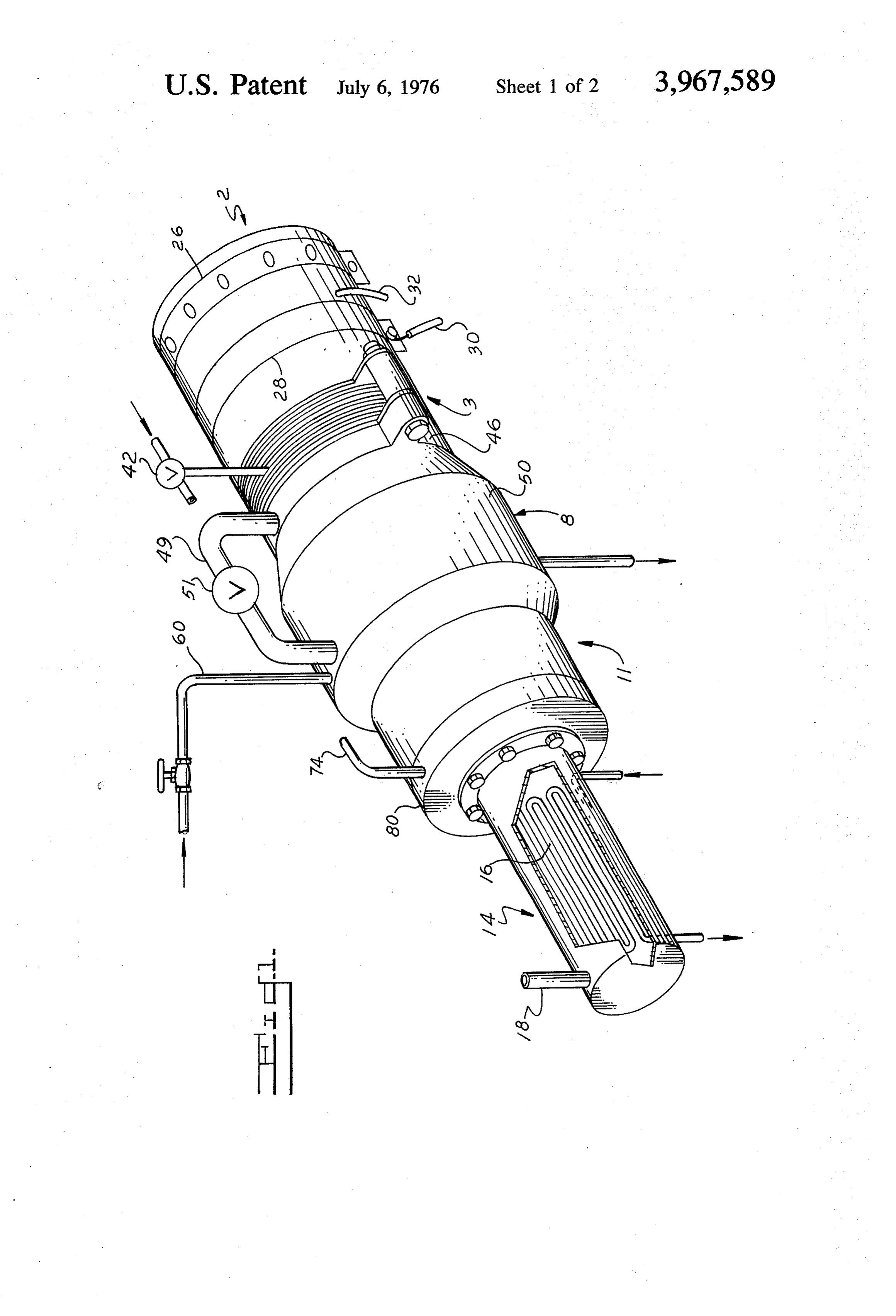
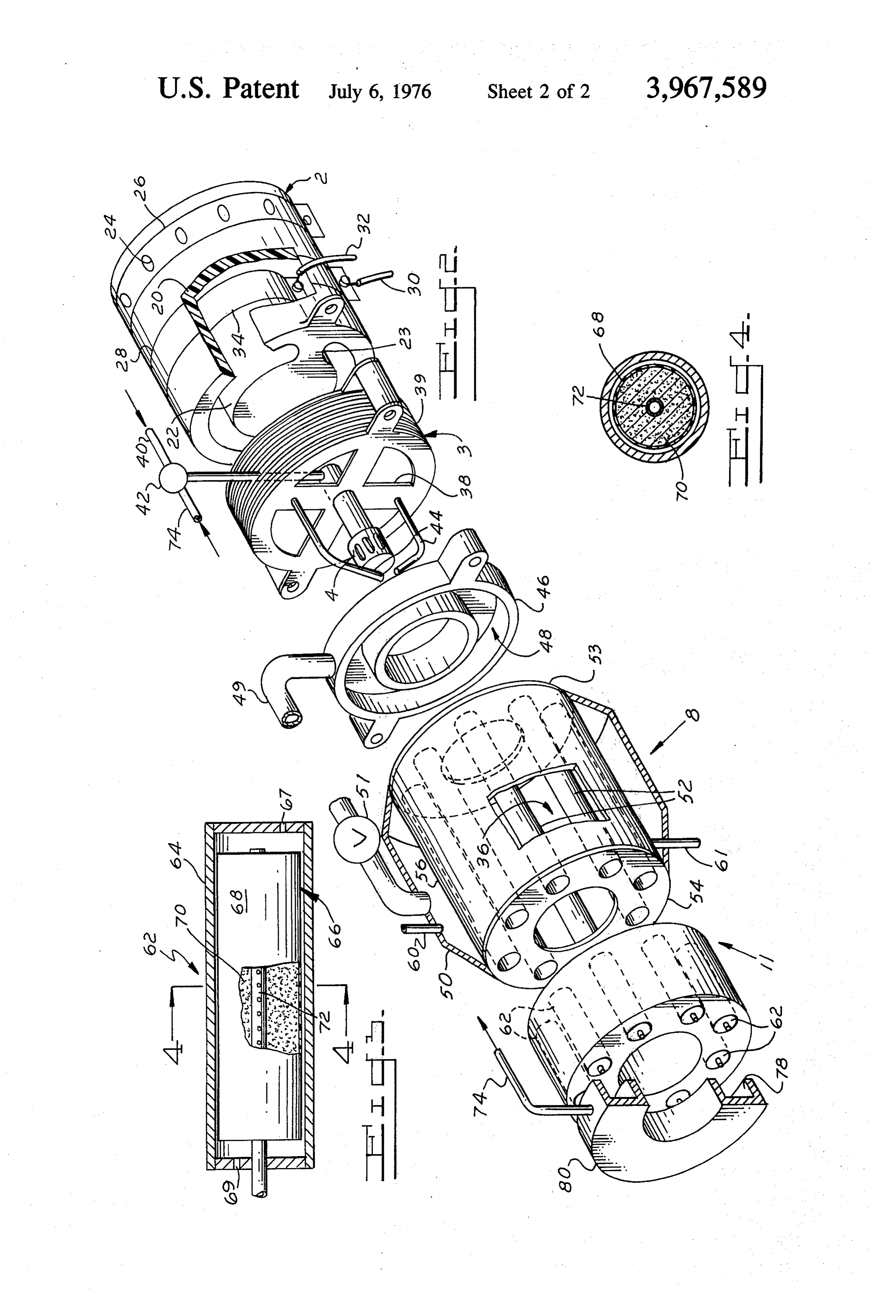
Hydrogen, because of its vast abundance in the water cable 32 extends through the wall of the shell and is molecule has been recognized for some time as the connected to a metallic plate 34 fitted around the outer primary candidate to replace the world's rapidly dwin surface of the core 22 in radially spaced relation to the dling fossil fuel reserves. Of course, the major draw plate 28. The space provided between the plates 28 and back heretofore encountered in attempting to use hy 34 and the voltage applied thereto is selected to pro drogen as an energy source has been the lack of an 10. duce an ozone enriched air supply for use in the com economically feasible process for obtaining hydrogen. bustion chamber 36 of the steam boiler-8. A circulating The principal object of this invention is to provide an fan (not shown) may be provided to insure an adequate efficient energy generating system characterized by its supply of air to the combustion chamber. minimal fossil fuel requirements. 2 The heat exchanger 3 commonly known as a heat Another object of this invention is to provide a mi 5 sink maintains a zone of moderate temperature be croporous membrane which is uniquely adapted to tween the ozone generator which utilizes air at ambient cause disassociation of high energy steam into its com temperature and the high temperatures of combustion ponent elements of hydrogen and oxygen. chamber 36 of the boiler. The heat sink comprises a A further object of this invention is to use a mem 20 cylinder, fabricated of a suitable metallic material, such brane of the above type in combination with a steam as aluminum, with a radially extending spider 38 for generator utilizing hydrogen as the primary fuel source supporting the nozzle 4. The outer surface of the heat for combustion. sink unit is provided with a plurality of radially extend The above and other objects of this invention will be ing, laterally spaced fins 39 for the rapid dissipation of more readily apparent from the following description heat from within the heat sink to the surrounding air. and with reference to the accompanying drawings, in 25 This unit protects the plastic ozone generator from which damage caused by overheating. The fuel nozzle or me FIG. 1 is an elevational view of one type of hydrogen tering device 4 extends from the spider 38 to a point generator embodying the concept of my invention; centrally of the combustion chamber 36 of the boiler. FIG. 2 is an exploded view of the generator of FIG. 1 30 The nozzle is supplied by way of appropriate tubing with parts thereof in section; connections as shown generally at 40 with a suitable FIG. 3 is a cross sectional view on an enlarged scale combustible fuel, such as propane or other liquified of a component of the generator of FIG. 1; and
FIG. 4 is a cross section taken along line 4-4 of FIG. trolling the flow of propane and/or a hydrogenforgascon petroleum. A regulator valve 42 is provided
Referring in detail to the drawings, an ozone genera 35 the nozzle, as will be more fully explained. tor is shown generally at 2. The outlet end of the ozone Electrodes 44, connected to a suitable source of generator is connected end-to-end with a tubular heat electrical potential (not shown), extend from the spider exchanger 3. A combustion nozzle 4 (FIG. 2) extends 38 of the heat sink and are positioned relative to the outwardly from the heat exchanger and is disposed nozzle for ignition of the fuel mixture issuing there- . within the combustion chamber of a boiler or steam 40 from. The voltage employed causes ignition of the fuel. generator, indicated generally at 8, in which steam is frontand serves to establish and maintain a stable flame developed by the heat of combustion derived from the pattern. Should the hydrogen supply furnished to fuel which issues from the nozzle 4. Steam from the the nozzle 4 become spasmodic, the continuous igni tion current will control the flame, preventing explo boiler 8 is ultimately fed to a diffusion membrane car 45 sions tridge 11, which causes molecular disassociation of the and assuring regular flame patterns, with a resul steam into hydrogen and oxygen gas. An economizer or tant positive controlled generation of heat. As shown in heat exchanger 14 (FIG. 2) receives the gaseous com FIG. 1, the heat sink cylinder abuts an end cap 46 bustion products from the combustion chamber of the which has an annular recess or chamber 48 opening boiler 8. These hot gases impinge upon a tube formed 50 toward the steam boiler 8. A pipe or conduit 49 pro as a coil 16 disposed within the heat exchanger. Water vides a passage to chamber 48 for steam generated in in the coil is heated for any use in any energy consum the jacket 50 of the boiler and a regulator valve 51 may ing system, such as for a steam or hot water supply be provided in this line to control the flow of steam system or heating system for industrial, commercial or from the boiler to the chamber 48. residential purposes. Exhaust gases from the heat ex In general, the boiler 8 comprises the combustion changer are vented to the atmosphere by a stack 18. 55 chamber 36 disposed centrally of a plurality of axially The ozone generator 2 comprises a tubular housing extending circumferentially spaced tubes 52 supported or shell 20 (FIG. 2) formed of any suitable material, at their outer ends by a pair of apertured end plates 53 such as a heat resistant synthetic plastic with an axial and 54. The boiler includes a steam jacket 50 which core 22 spaced from the inner surface of the shell 20 by 60 takes the form of an annular chamber disposed circum means of radially extending ribs 23. At its inlet end, the ferentially about the combustion chamber 36 and is housing includes a plurality of circumferentially spaced defined by an inner cylindrical wall 56 and an outer ports 24 opening into the annular chamber provided cylindrical wall of substantially larger diameter. The between the core 22 and the shell 20 of the generator. end portions of the outer wall taper inwardly to form a A plate 26 is disposed about the outer surface of the closed steam chamber. Feed water is supplied to the generator and includes a number of circumferentially 65 boiler jacket by inlet tube 60 and a drain tube 61 is spaced holes corresponding in number to the ports 24. provided for the combustion chamber to enable drain The plate is rotatable to vary alignment of its holes in age of excess moisture from the chamber caused by relation to the ports 24, thereby providing means for hydrogen combustion in air.
Page 5
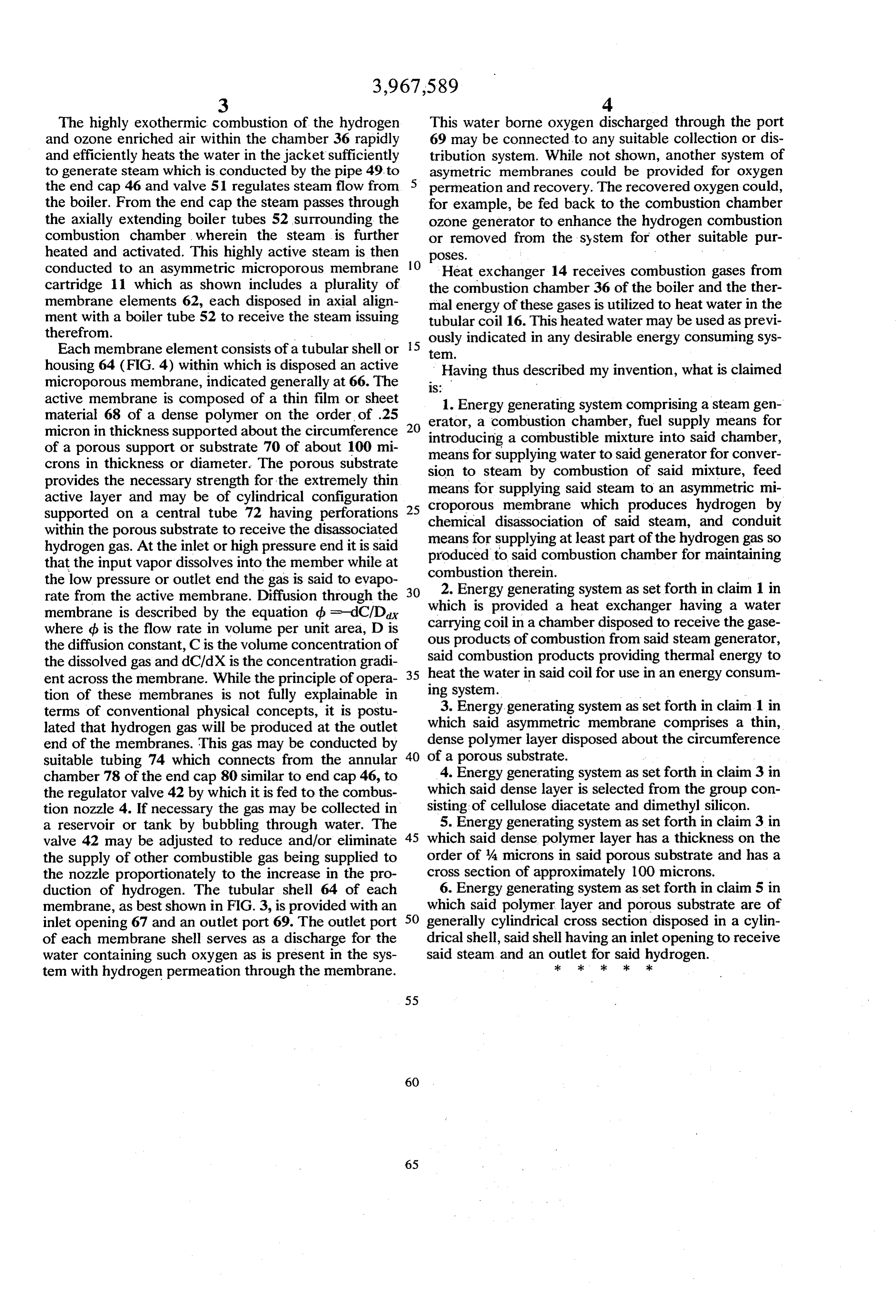
The highly exothermic combustion of the hydrogen This water borne oxygen discharged through the port and ozone enriched air within the chamber 36 rapidly 69 may be connected to any suitable collection or dis and efficiently heats the water in the jacket sufficiently tribution system. While not shown, another system of to generate steam which is conducted by the pipe 49, to asymetric membranes could be provided for oxygen the end cap 46 and valve 51 regulates steam flow from permeation and recovery. The recovered oxygen could, the boiler. From the end cap the steam passes through for example, be fed back to the combustion chamber the axially extending boiler tubes 52 surrounding the ozone generator to enhance the hydrogen combustion combustion chamber wherein the steam is further or removed from the system for other suitable pur heated and activated. This highly active steam is then poses.
conducted to an asymmetric microporous membrane O
Heat exchanger 14 receives combustion gases from cartridge 11 which as shown includes a plurality of the combustion chamber 36 of the boiler and the ther membrane elements 62, each disposed in axial align mal energy of these gases is utilized to heat water in the ment with a boiler tube 52 to receive the steam issuing tubular coil 16. This heated water may be used as previ therefrom. ously indicated in any desirable energy consuming sys Each membrane element consists of a tubular shell or 5 te.
housing 64 (FIG. 4) within which is disposed an active Having thus described my invention, what is claimed microporous membrane, indicated generally at 66. The S.
active membrane is composed of a thin film or sheet 1. Energy generating system comprising a steam gen material 68 of a dense polymer on the order of .25 20 erator, a combustion chamber, fuel supply means for micron in thickness supported about the circumference introducing a combustible mixture into said chamber, of a porous support or substrate 70 of about 100 mi means crons in thickness or diameter. The porous substrate sion toforsteam supplying water to said generator for conver by combustion of said mixture, feed provides the necessary strength for the extremely thin means for supplying active layer and may be of cylindrical configuration croporous membranesaid steam to an asymmetric mi which produces hydrogen by supported on a central tube 72 having perforations chemical disassociation of said
within the porous substrate to receive the disassociated means for supplying at least part ofsteam, and conduit the hydrogen gas so hydrogen gas. At the inlet or high pressure end it is said produced that the input vapor dissolves into the member while at combustionto therein.said combustion chamber for maintaining the low pressure or outlet end the gas is said to evapo 2. Energy generating system as set forth in claim 1 in rate from the active membrane. Diffusion through the which is provided a heat exchanger having a water membrane is described by the equation d = dC/Dax where b is the flow rate in volume per unit area, D is carrying ous coil in a chamber disposed to receive the gase products of combustion from said steam generator, the diffusion constant, C is the volume concentration of said combustion products providing thermal energy to the dissolved gas and dC/dX is the concentration gradi 35 heat ent across the membrane. While the principle of opera ing system. the water in said coil for use in an energy consum tion of these membranes is not fully explainable in 3. Energy generating system as set forth in claim 1 in terms of conventional physical concepts, it is postu lated that hydrogen gas will be produced at the outlet which said asymmetric membrane comprises a thin, end of the membranes. This gas may be conducted by 40 dense polymer layer disposed about the circumference suitable tubing 74 which connects from the annular of4.a Energy porous substrate.
generating system as set forth in claim 3 in chamber 78 of the end cap 80 similar to end cap 46, to the regulator valve 42 by which it is fed to the combus which said dense layer is selected from the group con tion nozzle 4. If necessary the gas may be collected in sisting of cellulose diacetate and dimethyl silicon. a reservoir or tank by bubbling through water. The 5. Energy generating system as set forth in claim 3 in valve 42 may be adjusted to reduce and/or eliminate 45 which said dense polymer layer has a thickness on the the supply of other combustible gas being supplied to order of 4 microns in said porous substrate and has a the nozzle proportionately to the increase in the pro cross section of approximately 100 microns. duction of hydrogen. The tubular shell 64 of each 6. Energy generating system as set forth in claim 5 in membrane, as best shown in FIG. 3, is provided with an SO which said polymer layer and porous substrate are of inlet opening 67 and an outlet port 69. The outlet port generally cylindrical cross section disposed in a cylin of each membrane shell serves as a discharge for the drical shell, said shell having an inlet opening to receive water containing such oxygen as is present in the sys said steam and an outlet for said hydrogen. tem with hydrogen permeation through the membrane. ck : " : k k
Provenance
- Collection
- Cited prior art
- Original PDF
- patentimages.storage.googleapis.com →
- Filed
- 1975-01-27
- Pages
- 5
- Method
- pdftotext (the PDF's own text layer) + pdftoppm 300dpi page scans
- Source
- Google Patents bibliographic record
- Granted
- 1976-07-06
- Inventors
- Ronald I. Papineau
- Transcribed from
- patentimages.storage.googleapis.com →