patent · US3963000
System for reforming engine fuel into hydrogen gas-containing mixture by catalytic reaction
15 June 1976
Page 1 — bibliographic record
United States Patent (19) 11 3,963,000 Kosaka et al. (45) June 15, 1976
(54) SYSTEM FOR REFORMING ENGINE FUEL 3,672,341 6/1972 Smith et al................... 123/DIG. 2 3,682,142 8/1972 Newkirk ...................... 123/DIG. 12
INTO HYDROGEN GAS-CONTAINING 3,709,203 1/1973 Cettin et al..................... 1231 A X MIXTURE BY CATALYTIC REACTION 3,717, 129 2/1973 Fox..................................... 12311 A (75) Inventors: Katuaki Kosaka, Tokyo; Zene Ueno, 3,798,005 3/1974 Koch..................................... 48107 Fuchu; Tadahiko Nagaoka, 3,817,232 6/1974 Nakajima et al................ 12311 A X 3,828,736 8/1974 Koch....................................... 23/3
Tokorozawa, all of Japan 3,871,838 3/1975 Henkel et al...... ... 48/107 73) Assignee: Nissan Motor Co., Ltd., Yokohama, 3,897.225 7/1975 Kodi................................... 123/3 X Japan
Primary Examiner-Charles J. Myhre 22) Filed: Dec. 19, 1974 Assistant Examiner-Ira S. Lazarus
(30) Foreign Application Priority Data The system fundamentarily consists of a means to pre Mar. 6, 1974 Japan................................ 49-25915 pare a substantially gaseous mixture of a fuel, e.g., hy drocarbons, oxygen and water, a heated catalyst (52) U.S. Cl................................... 123/3; 123125 R; chambur and a reciprocating compressor. The com 123/1 A; 12311 19 A; 12311 19 E; 48/107 pressor is arranged and valve-controlled such that the 51 Int. Cl.’.......................................... F02B 43/08 fuel mixture is pressurized before the feeding into the 58 Field of Search................ 123/1 A, 3, 66, 69 R, catalyst chamber and the heated and pressurized H 123/119 R, 1 19 A, 19 C, 25 R, 119 E; containing mixture is drawn into and expanded in the 48/102 A, 107 working chamber of the compressor before the feed ing into an engine. The means to prepare the starting 56) References Cited fuel mixture may include a sub-system for producing UNITED STATES PATENTS oxygen and water from hydrogen peroxide.
3,635,200 11 1972 Rundell et al.......................... 23/3 8 Claims, 3 Drawing Figures
Page 2
Drawing sheet — no readable text.
Page 3
compressor. The compressor is constructed such that
SYSTEM FOR REFORMING ENGINE FUEL INTO the primary mixture is compressed in the working HYDROGEN GAS-CONTAINING MIXTURE BY chamber thereof and subsequently forced out into the CATALYTIC REACTION reaction chamber and that the fuel mixture reformed in the reaction chamber is drawn into and expanded in the
This invention relates to a system for reforming an working chamber and subsequently discharged there organic fuel for feeding into an engine into another from into the engine.
type of fuel mixture containing a relatively large theTheefficiencies advantages of the invention reside mainly in that of the reformation reactions in the amount of hydrogen gas by catalytic reactions with 10 oxygen and water. reaction chamber are improved due to the feeding of It is well known that organic fuels such as hydrocar the pressurized primary mixture, and that the expan bons derived from petroleum and oxygen-containing sion of the reformed mixture in the working chamber compounds such as alcohols, aldehydes and ketones not only achieves the reduction in the pressure and can be reformed or converted into fuel mixtures con temperature of the reformed mixture but also allows taining relatively large amounts of hydrogen gas. For 15 the compressor to run self-sustainingly. example, a mixture of atomized light oil, oxygen (or According to the invention, the first means may in air) and water is converted into a differently composed clude a sub-system for catalytically decomposing hy hot gaseous mixture containing hydrogen, carbon mon drogen peroxide into a heated mixture of oxygen and oxide, carbon dioxide and possibly steam upon contact 20 water, so that the efficiencies of the reformation reac with a nickel or lime-base catalyst heated to about tion are further improved.
800°C. The similar conversion can be accomplished The invention will be fully understood from the fol with methanol by using a zinc oxide and/or chromium lowing detailed description of the preferred embodi oxid-base catalyst heated to about 300°C. ments thereof with reference to the accompanying These techniques have been applied to various en 25 drawings, in which:
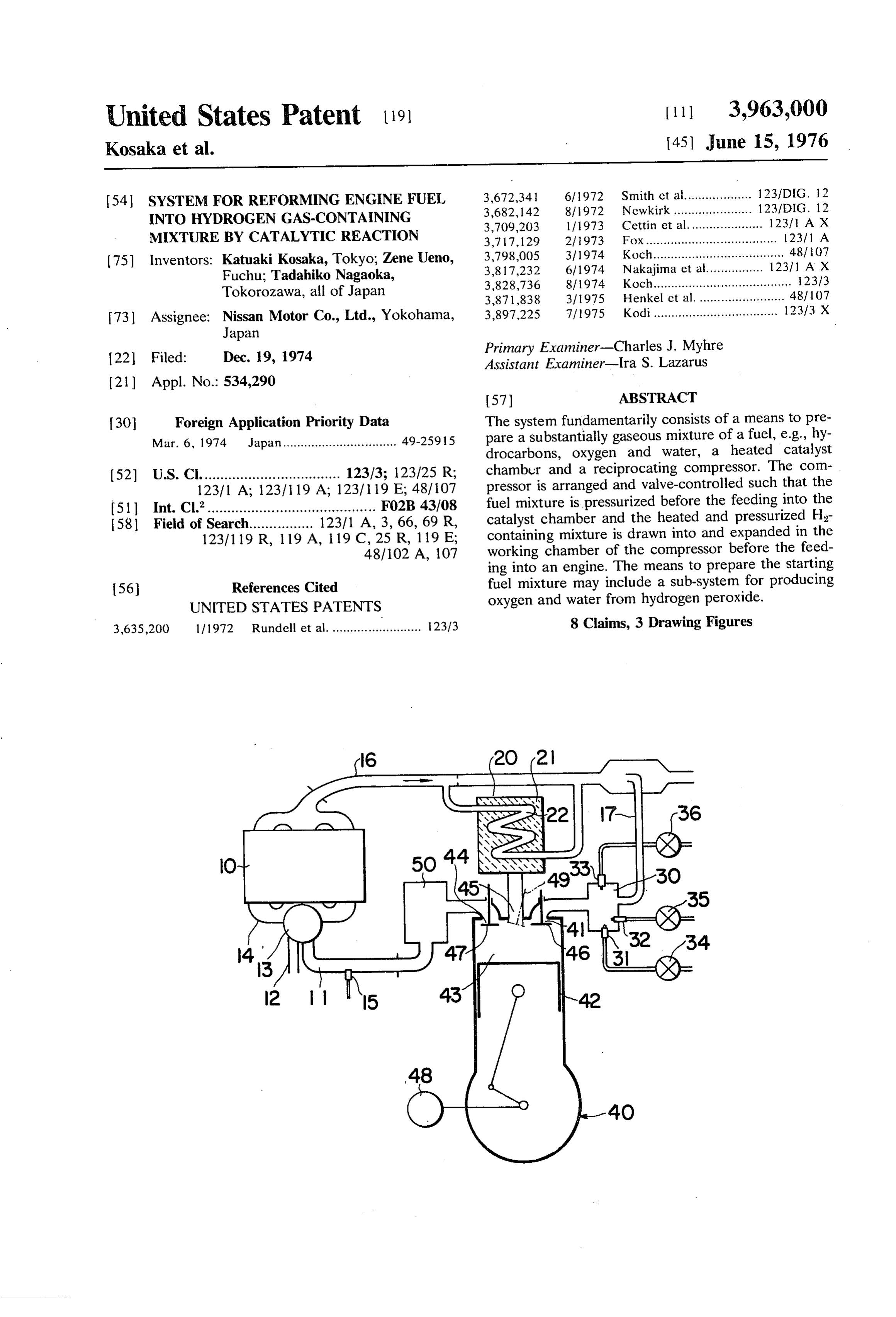
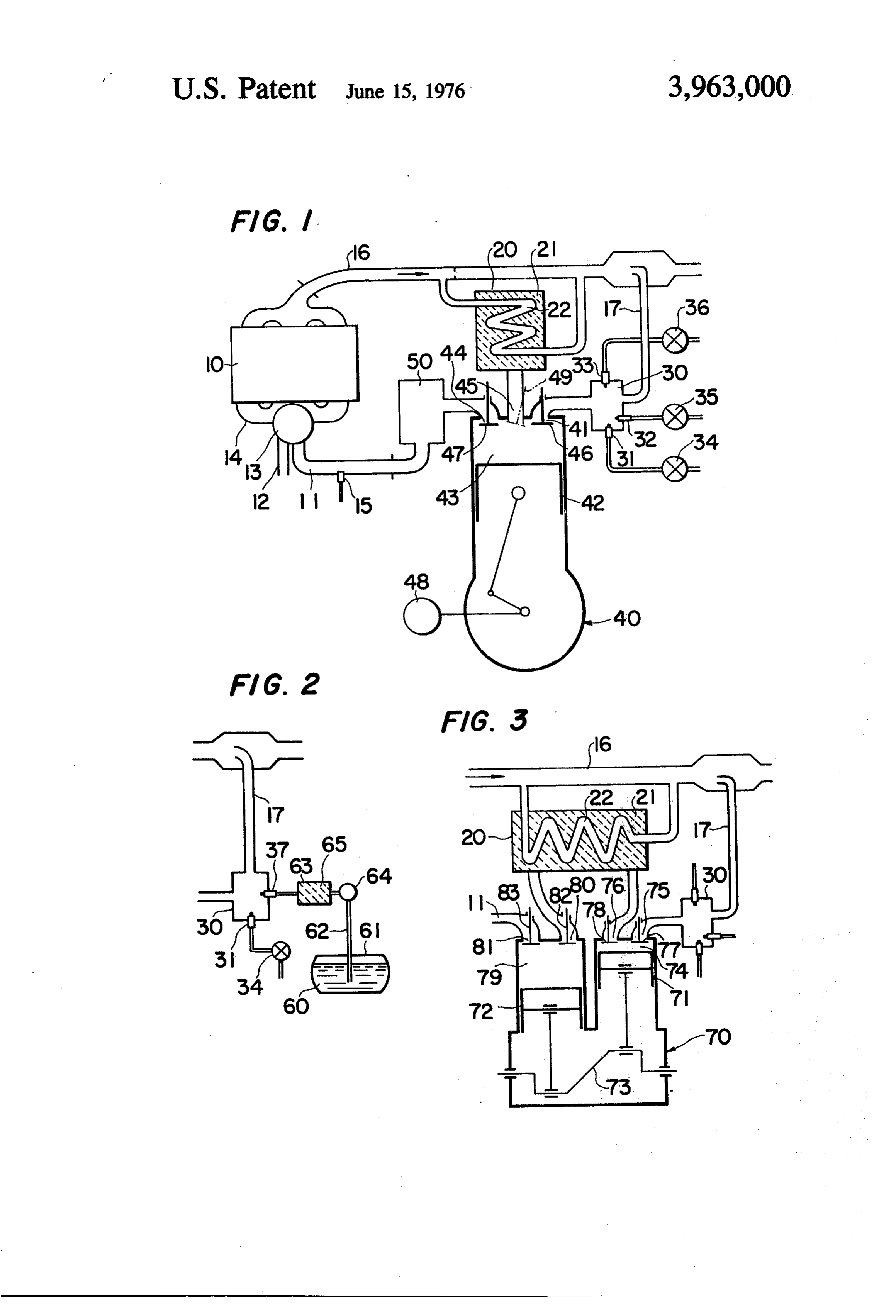
gines including automotive engines because a hydro FIG. 1 is a diagram showing a general constitution gen-gas containing fuel is advantageous for reducing and arrangement of a system according to the invention the concentrations of harmful substances in the exhaust for reforming a fuel prior to the feeding thereof into an gas. It has been proposed in the field of automotive engine;
engines to utilize the engine exhaust gas as a heat FIG. 2 is a diagram showing a slight and local modifi source for heating the catalyst and/or utilize the water 30 cation of the system of FIG. 1 by the provision of a in the exhaust gas as at least a portion of the water sub-system for producing oxygen and water from hy component of the starting mixture. The resulting hy drogen peroxide; and drogen-containing gaseous mixture is cooled to an ade FIG. 3 is a diagram showing a variation of the com quate temperature and supplied to the engine as the 35 pressor in the system of FIG. 1. main or an auxiliary fuel. In FIG. 1, the reference numeral 10 indicates a con It is of practical importance that a mixture of an ventional engine, e.g., of a motor vehicle. The intake ordinary fuel, oxygen (or air) and water (hereinafter system of the engine 10 includes a fuel induction pas will be referred to simply as the primary mixture) is sage 11, an air induction passage 12, a mixer 13 for the converted into a gaseous fuel mixture containing a 40 preparation of a combustible mixture and an intake relatively large amount of hydrogen together with car manifold 14. The fuel induction passage 11 is equipped bon monoxide (hereinafter will be referred to as the with a fuel injection nozzle 15 communicating with a reformed mixture) in good efficiency, particularly with usual fuel system (not shown). The engine 10 is pro respect to relatively small-sized systems such as the vided with an exhaust pipe 16, and preferably a recircu conversion systems for automotive engines. As men 45 lation duct 17 is branched therefrom to recirculate a tioned above, the reformed mixture may further con portion of the exhaust gas into the intake system. A conventional reaction chamber 20 for the fuel tain minor amounts of carbon dioxide and steam.
It is an object of the present invention to provide an reformation contains a catalyst 21 and a heat ex improved system for reforming the above described changer 22. The heat exchanger 22 is connected to the primary mixture into the above described reformed 50 exhaust pipe 16 so as to cause a portion of the hot mixture for use in an engine, which system allows the exhaust gas to pass therethrough on the way to the reformation reactions to be accomplished in improved branch point of the recirculation duct 17. The catalyst efficiencies and the pressure and temperature of the 21 is selected from various conventional catalysts reformed mixture to be reduced effectively. which catalyze the decomposition or hydrogenation of The invention is concerned with a known system, 55 organic fuels such as hydrocarbons, alcohols, alde which fundamentarily consists of first means to prepare hydes and/or ketones (hereinafter will be referred to as the primary mixture containing at least an organic fuel, the primary fuel) at elevated temperatures. For exam oxygen and water substantially in the gaseous form, a ple, a nickel-base catalyst or a mixture of calcium oxide reaction chamber containing a catalyst capable of con and magnesium oxide is usually used for a hydrocarbon verting the primary mixture into a gaseous fuel mixture fuel such as gasoline. A mixture of chromium oxide and containing at least hydrogen and carbon monoxide, and 60 zinc oxide is suitable for methanol. A fluid mixer 30 for second means to heat the catalyst. According to the the preparation of the primary mixture is equipped with invention, the system further comprises a reciprocating a fuel nozzle 31, an oxygen nozzle 33 communicating compressor having at least one working chamber de with the respective substances sources (not shown) via fined above a piston and provided with an intake valve 65 valves 34, 35 and 36, respectively. Air is frequently and a discharge valve. The compressor is fluidly con used as the oxygen source. The exhaust gas recircula nected with the first means, the reaction chamber and tion duct 17 is connected to the mixer 30. an engine such that both the first means and the engine In conventional systems for reforming the primary communicate with the reaction chamber through the fuel, the fluid mixer 30 directly communicates with the
Page 4
reaction chamber 20. According to the invention, how reformed mixture is drawn into the mixer 13 through ever, the mixer 30 is connected to an intake port 41 of the fuel induction passage 11 and mixed with air from a compressor 40. The compressor 40 has a reciprocat the induction passage 12 prior to the feeding to the ing piston 42, a working chamber 43 defined above the 5 engine 10.
piston 42, a discharge port 44 and an interjacent port Due to the preliminary compression of the primary 45. The interjacent port 45 allows the working cham mixture, the reactions in the reaction chamber 20 pro ber 43 to communicate directly with the reaction ceed more efficiently or at increased rates of reactions chamber 20. The discharge port 44 is connected to the than in the similar chamber in conventional systems for fuel induction passage 11 of the engine 10 preferably the following reasons. The effective surface areas of the through a gas reservoir 50. The intake port 41 and the O catalyst 21 can be substantially increased since the discharge port 44 are respectively provided with an pressurized primary gaseous mixture permeates even intake valve 46 and a discharge valve 47. The compres into agglomerate and/or capillary regions of the cata sor 40 is equipped with a starter 48 or alternatively lyst 21. Thus the catalytic reactions of the primary fuel associated with the engine 10 through a clutch mecha 15 with the oxygen and steam are accelerated. Besides, the nism (not shown) for the starting thereof. high pressure in the reaction chamber 20 enhances the In operation, the engine 10 is operated by an air-fuel heat conduction from the catalyst 21 and the heat ex mixture resulting from the injection of an ordinary fuel changer 22 to the primary mixture. such as gasoline from the nozzle 15 during an initial The reformed mixture may be expanded prior to the stage of the idling for warm-up. When the catalyst 21 is feeding into the fuel induction passage 11 in any man heated to a predetermined temperature by the exhaust ner, but the expansion in the working chamber 3 of the gas flowing through the heat exchanger 22, the fuel compressor 40 is advantageous from the viewpoint of injection from the nozzle 15 is stopped or restricted to utilizing the force of the expansion most effectively. a lower rate, and at the same time the three valves 34, The work done on the piston 42 by the expanding mix 35 and 36 are opened to inject the primary fuel, oxygen ture is sufficient in magnitude to allow the compressor or air and water into the mixer 30. As a result, the 25 40 to run self-sustainingly or with the aid of no external primary mixture is produced substantially in the gase power. Sometimes the compressor 40 even can supply ous form and further mixed with the exhaust gas recir a certain magnitude of surplus power to the engine 10 culated into the mixer 30. The rate of the water supply or auxiliary devices.
from the nozzle 32 is determined taking into consider 30 The interjacent port 45 of the compressor 40 may be ation the water content of the recirculated exhaust gas. provided with a valve 49 as shown by a phantom line in These functions of the engine 10, heat exchanger 22 FIG. 1. This valve 49 is opened at a later stage of the second stroke and closed at the end of the third stroke.
and the mixer 30 are similar to those in a conventional system. As a result, the compressed primary mixture can be In the system of FIG. 1, the compressor 40 is started 35 discharged from the working chamber 43 more rapidly when the preparation of the primary mixture in the and easily during the second stroke, causing the reac mixer 30 is commenced. The intake and discharge tions in the reaction chamber 20 to be accelerated and valves 46 and 47 are controlled so as to allow the pri the magnitude of the work for the compression to be mary mixture to behave in the following manners. Dur reduced.
ing the first stroke of the piston 42, the intake valve 46 40 Practically it is not so easy to supply pure oxygen to is open but the discharge valve 47 is closed, so that the the fluid mixer 30 especially when the engine 10 is of a primary mixture is drawn into the working chamber 43 relatively small size or loaded on a vehicle, so that air is as the piston 42 moves downward. Both the two valves usually employed as the oxygen source. Air is, how 46 and 47 are closed during the second or upward ever, disadvantageous for the reactions in the reaction stroke of the piston 42, so that the primary mixture in 45 chamber 20 because of its large nitrogen content. We the working chamber 43 is compressed and gradually have contemplated hydrogen peroxide as a preferable forced out into the reaction chamber 20 through the oxygen source for the system of FIG. 1. As is known, interjacent port 45. The primary mixture is compressed hydrogen peroxide undergoes a catalytic decomposi to such an extent that the resulting pressure in the tion into oxygen and water upon contant with a silver reaction chamber 20 is between about 20 and about 30 or nickel-base catalyst. The decomposition reaction is kg/cm. Thus the primary mixture comes into contact 50 exothermic, so that the gaseous products of the decom with the heated catalyst 22 and turns into the reformed position are obtained at high temperatures ranging mixture containing a relatively large amount of hydro from about 230 to about 750°C when an aqueous gen gas together with carbon monoxide and carbon solution of hydrogen peroxide in the concentration range of 50 to 90% is employed. This gaseous product dioxide. The reformed mixture is at an elevated tem perature and still under a high pressure. On the third 55 exhibits a strong chemical activity due to the presence stroke, the two valves 46 and 47 are still closed and the of a nascent oxygen therein besides the elevated tem perature thereof. Therefore, the employment of the piston 42 moves downward. Accordingly, the reformed decomposition mixture flows into the working chamber 43 and ex product of hydrogen peroxide as the pands threrein substantially adiabatically. The expan 60 oxygen and water sources for the primary mixture can sion of the hot mixture results in the reduction of the aid the heating of the catalyst 21 and facilitate the mixture temperature and does the work of pushing oxidation of the carbon components in the primary down the piston 42. On the fourth stroke, the discharge fuel.
valve 47 is opened and the piston 42 moves upwardly to FIG. 2 shows a preferred embodiment of the utiliza deliver the reformed mixture into the reservoir 50. The tion of hydrogen peroxide in connection with the mixer above four strokes are cycled during the running of the 65 30 of FIG. 1. In this system, the oxygen nozzle 32 and engine 10. The reformed mixture is intermittently dis water nozzle 33 of FIG. 1 are replaced with a single charged from the compressor 40 on each cycle and nozzle 37. The mixer 30 is unvaried in other respects. temporarily stored in the reservoir 50. Thereafter the An aqueous solution of hydrogen peroxide 60 is kept in
Page 5
a tank 61, and a pipe 62 connects the tank 61 to a almost continuous presence of the hot and pressurized decomposition chamber 53 interposing a pump 64. The reformed mixture in the reaction chamber 20. chamber 63 contains a conventional catalyst 65 for the The compressor 70 of FIG. 3 can be employed decompositions of the hydrogen peroxide solution 60 whether the hydrogen peroxide system of FIG. 2 is and communicates with the nozzle 37. employed or not since the function of the compressor The pump 64 is operated simultaneously with the fuel 70 or 40 is independent of the gas sources for the prep valve 34, so that a mixture of the primary fuel, oxygen, aration of the primary mixture. What is claimed is:
water and the recirculated exhaust gas is produced in the mixer 30 in a generally similar manner as in the 10 1. A system for the preparation of a fuel mixture to case of FIG. 1. The thus produced primary mixture is feed into an engine, comprising: first means to prepare then introduced into the compressor 40 and subjected a substantially gaseous first mixture at least of an or ganic fuel, oxygen and water, a reaction chamber con to the process as described with regard to FIG. 1. The taining concentration of the hydrogen peroxide solution 60 therein a catalyst capable of converting said. may be varied depending on the desired amount of the 15 first mixture into a gaseous second mixture at least of water to feed to the mixer 30. hydrogene and carbon monoxide at elevated tempera In a system of the invention, the compressor 40 is not tures; second means to heat said catalyst, and a recipro limited to the one of FIG. 1, but may be modified to definedcompressor cating having at least one working chamber various forms. FIG. 3 shows an example of the modifi valve andabove a piston and provided with an intake a discharge valve; said compressor being cation. This compressor 70 has two pistons 71 and 72 20 fluidly connected with said first means, said reaction connected to a single crank 73. A first working cham chamber and the engine such that both said first means ber 74 is defined above the first piston 71 and commu and the engine communicate with said reaction cham nicable with the mixer 30 through a first intake port 75 ber through said working chamber, and with the reaction chamber 20 through a first dis being constructed such that said first said compressor mixture is com charge port 76. The two ports 75 and 76 are respec 25 pressed in said working chamber and subsequently tively equipped with a first intake valve 77 and a first forced out into said reaction chamber to enhance the discharge valve 78. A second working chamber 79 is efficiencies of the reactions in said reaction chamber, defined above the second piston 72 so as to communi and that said second mixture is drawn into and ex cate with the reaction chamber 20 through a second intake port 80 and with the fuel induction passage 11 of 30 panded ature of in said working chamber to reduce the temper said second mixture and sustain the operation the engine 10 through a second discharge port 81. The of said compressor, and subsequently discharged there two ports 80 and 81 are equipped with a second intake from to the engine.
valve 82 and a second discharge valve 83, respectively. 2. A system according to claim 1, wherein said com One operation cycle of this compressor 70 consists of pressor has a single reciprocating piston and a single two strokes of the pistons 71 and 72, and the two pis 35 working chamber defined above said piston, said work tons 71 and 72 moves always in the opposite directions. ing chamber being communicable with said first means On the first stroke, the first intake valve 77 and the and the engine through said intake port and said dis second discharge valve 83 are opened and the first charge port thereof, respectively, and communicating piston 71 moves downward, so that the primary mix with said reaction chamber through an interjacent port ture is drawn into the first working chamber 74. Then 40 thereof, said intake and discharge ports being equipped the two valves 77 and 83 are closed, and the first dis with an intake valve and a discharge valve, respec charge valve 78 and the second intake valve 80 are tively, said intake and discharge valves being timed opened on the second stroke. On this stroke, the first such that said first mixture is sucked into said working piston moves upwardly to compress the primary mix chamber on a first and downward stroke of said piston ture in the first working chamber 74 and discharge it 45 and then compressed and forced out into said reaction into the reaction chamber 20. Then the primary mix chamber during a second and upward stroke of said ture turns into the reformed mixture, which is at a high piston, and that said second mixture is sucked into said temperature and pressurized. The reformed gas is working chamber on a third and downward stroke of drawn into the second working chamber 75 through the said piston and then discharged into the engine on a second intake port 80 and expanded therein during the 50 fourth and upward stroke of said piston. second stroke, and thereafter discharged therefrom 3. A system according to claim 2, further comprising through the second discharge port 81 during the next a gas reservoir arranged between said discharge port of first stroke. said compressor and the engine. It will be apparent that the important features of the 4. A system according to claim 2, wherein said inter invention, i.e., the compression of the primary mixture 55 jacent port is equipped with a valve timed in such a prior to the feeding into the reaction chamber 20 and manner that said valve is opened at a later stage of said expansion of the reformed mixture in the working second stroke and closed at the end of said third stroke. chamber 79 of the compressor 70 are accomplished 5. A system according to claim 1, wherein said com fundamentarily in the similar ways as in the case of pressor has two pistons connected to a single crank so FIG. 1 despite the difference in the compressor 70. The 60 as to reciprocate in the opposite directions to each temperature reduction of the reformed mixture and the other and two separate working chambers defined self-sustaining running of the compressor 70 are also above the respective pistons, the first working chamber similarly attained. In addition to these unvaried fea being communicable with said first means and said tures, the arrangement of FIG. 3 has the advantages reaction chamber through an intake port and a dis that the efficiencies of the reactions in the reaction 65 charge port thereof, respectively, the second working chamber 20 are further improved due to the nearly chamber being communicable with said reaction cham continuous supply of the pressurized primary mixture ber and the engine through an intake port and a dis and that the compressor 70 runs more smoothly due to charge port thereof, respectively, all of said intake and
Page 6
discharge ports of said first and second working cham means 6. A system according to claim 1, wherein said first bers being equipped with intake and discharge valves, water byincludes third means to prepare oxygen and a catalytic decomposition of an aqueous solu respectively, said intake and discharge valves being tion of hydrogen peroxide.
timed such that said first mixture is sucked into said 7. A system according to claim 1, wherein said first first working chamber on a first and downward stroke means is fluidly connected with an exhaust system of of said first piston and then compressed and forced out the engine such that a portion of the engine exhaust gas is mixed with said first mixture.
into said reaction chamber during a second and upward 8. A system according to claim 1, wherein said sec stroke of said first piston, and that said second mixture 10 ond means is a heat exchanger disposed in said reaction is sucked into said second working chamber on said chamber and arranged such that at least a portion of second stroke and then discharged into the engine on the exhaust gas from: said ck engine
passes
therethrough.
said first stroke.
Provenance
- Collection
- Cited prior art
- Original PDF
- patentimages.storage.googleapis.com →
- Filed
- 1974-12-19
- Pages
- 6
- Method
- pdftotext (the PDF's own text layer) + pdftoppm 300dpi page scans
- Source
- Google Patents bibliographic record
- Granted
- 1976-06-15
- Inventors
- Katuaki Kosaka; Zene Ueno; Tadahiko Nagaoka; Nissan Motor Co Ltd
- Transcribed from
- patentimages.storage.googleapis.com →