patent · US3817232
Method and apparatus for reducing toxic compounds in exhaust gases from combustion type power plant
18 June 1974
Page 1 — bibliographic record
United States Patent 19 11) 3,817,232 Nakajima et al. (45) June 18, 1974 54 METHOD AND APPARATUS FOR 3,489,144 1/1970 Dibelius et al.................... 55/158 X REDUCING TOXC COMPOUNDS IN 3,509,694 5/1970 Imai et al.......................... 55/58 X
EXHAUST GASES FROM COMBUSTION
TYPE POWER PLANT Primary Examiner-Wendell E. Burns 75 Inventors: Yasuo Nakajima; Toru Yoshimura;
Shin-Ichi Nagumo, all of Yokosuka, 57) ABSTRACT
Japan 73 Assignee: Nisson Motor Company, Limited, Herein disclosed are a method of and apparatus for Yokohama City, Japan reducing toxic compounds especially nitrogen oxides in exhaust gases from various power plants of the (22) Filed: June 20, 1972 combustion type, such as the automotive engines and 21 Appl. No.: 264,576 industrial boilers. In the method herein disclosed, the fuel for the power plant is mixed with denitrified air and recirculated exhaust gases and, where desired, 30 Foreign Application Priority Data with additional fresh air. The denitrified air is ob Nov. 25, 1971 Japan................................ 46-94O73 tained by separation of nitrogen molecules from atmo Nov. 22, 1971 Japan................................ 46-93O3 spheric air by the use of nitrogen separating means us ing, for example, a nitrogen impermeable membrane 52 U.S. C. ......... 123/119 A, 123/1 A, 113/119 E, or a certain type of molecular sieve which may be 113/198 E, 55/158, 60/278 formed of pulverized zeolite. Deterioration of the ni 51) Int. Cl............................................ F02m 25/06 trogen separating ability of the separating means as a 58) Field of Search ........ 123/1 19 A, 119 E, 198 E, result of depositor accumulation of the nitrogen mol 123/1 A; 55/158; 601278, 279 ecules thereon is cyclically remedied through periodic purging of the nitrogen separating means. The nitro 56) References Cited gen oxides in the exhaust gases are reduced about 95 UNITED STATES PATENTS per cent and the hydrocarbons, carbon monoxides and 657,770 9/1900 Hedrick................................ 55/158 sulfides are reduced about two thirds as compared 2,444,222 6f 1948 Craig............................... 123/119 E with the conventional combustion systems. 3,332,216 7|1967 Stern..................................... 55/158 11 Claims, 6 Drawing Figures
Page 2
Drawing sheet — no readable text.
Page 3
Drawing sheet — no readable text.
Page 4
Drawing sheet — no readable text.
Page 5
Drawing sheet — no readable text.
Page 6
Drawing sheet — no readable text.
Page 7
METHOD AND APPARATUS FOR REDUCING and which are not fully acceptable for the complete de TOXC COMPOUNDS IN EXHAUST GASES FROM composition of the nitrogen oxides. COMBUSTION TYPE POWER PLANT The present invention proposes a new and novel method and apparatus by which the concentration of
The present invention relates to power plants of com the nitrogen oxides in the engine exhaust gases is mini bustion type and, more particularly, to a method and mized and, at the same time, the concentration of the apparatus for reducing toxic compounds such as nitro hydrocarbons and carbon monoxides is reduced to a gen oxides contained in exhaust gases from the com considerable extent without resort to provision of an bustion power plants. independent system which is specifically adapted to re A variety of means have thus far been developed and 10 duce such combustible compounds. The goal of this na practised in an attempt to provide useful solution to the ture can be attained basically through mixing the fuel air-pollution poblems caused by the operation of the for the engine with air from which nitrogen is removed power plants of the combustion type such as the en so that the exhaust gases from the engine contain sub gines of the motor vehicles. It appears that such air stantially no nitrogen oxides. Such air void of the nitro pollution problems arise from the sue of use only the 5 gen is herein referred to as denitrified air which con internal combustion engines but even the engines of the tains an oxygen gas in a major proportion and chemi external combustion type such as the gas turbines of cally stable rare gases in an appreciable proportion. the closed type. The toxic compounds in the engine ex Where, thus, the fuel is combusted in the engine by the haust gases usually include nitorgen oxides and un aid of the denitrofied air containing mainly the oxygen burned or partially burned combustible compounds gas, the combustion will proceed at so rapid a rate as such as hydrocarbons and carbon monoxides. The hy atodanger be objectionable for practical purposes and to invite during operation of the engine.
drocarbons and carbon monoxides tend to be produced as a result of incomplete combustion of the air-fuel It is, thus, an object of the present invention to pro mixture in the engines while the nitrogen oxides tend 25 vide a method of and an apparatus for minimizing the to be produced when the engines are operating at rela concentration of the nitrogen oxides in the exhaust tively high temperatures, as is well known in the art. while gases from various power plants of the combustion type Where arrangements are made so that the air-fuel mix silumtaneously reducing the concentration of the unburned ture be burned completely before the engine exhaust exhaust gases hydrocarbons and carbon monoxides in the gases are discharged, the concentration of the nitrogen in a simplified manner. It is another oxides in the exhaust gases, increase by reason of the method of and apparatus object of the invention to provide a enhanced chemical reaction between oxygen and nitro tions of the toxic compounds for reducing the concentra gen. If, on the contrary, it is desired that the concentra the combustion power plantsin without the exhaust gases from impairing the tion of the nitrogen oxides be reduced satisfactorily, combustion efficiencies of the power plants. the combustion of the air-fuel mixture in the engine is 35 It is further and another object of the present inven liable to become incomplete and, as a result, an in tion to provide a method and apparatus in which total creased amount of hydrocarbons and carbon monox concentration ides are produced. Attempts have therefore be made so gases from theofcombustion the toxic compounds in the exhaust as to provide compromise between these mutually con which is readily operable withpower a plants in a manner low cost and in a sim flicting requirements especially in the field of the motor 40 ple construction.
industry. The present invention thus contemplates pro To achieve these objects of the present invention, a vision of an advanced solution to this problem.
Under the condition in which the combustion engines plant is of stream air to be mixed with the fuel for the power are driven at relatively high temperatures, the intorgen so that the airpassed first through nitrogen separating means is substantially denitrified to contain an oxides are produced through chamber reaction be oxygen gas in a major proportion. The thus denitrified
tween the oxygen and nitrogen in the atmosphere. In the case of the nitrogen monoxide, such reaction takes air is mixed with the exhaust gases which are recircu lated from the power plant at a controlled rate. It is, in place as follows: this instance, preferred that the denitrified air and re N -- O - 2NO. 50 circulated exhaust gases be mixed with each other in a proportion substantially corresponding to the ratio be
It is known that the nitorgen moxide is produced in tween the oxygen and nitrogen of the normal atmo a large quantity especially when the engines are operat spheric air. The resultant mixture of the denitrified air ing at high temperatures and, for this reason, the con and recirculated exhaust gases are then mixed with the centration of the nitrogen moxide could be reduced if 55 fuel in a liquid or emulsion state in a predetermined the engine operates at reduced temperatures. This, proportion. The combustible mixture obtained in this however, is reflected by reduction in the combustion manner is supplied to the power plant for combustion efficiencies and accordingly an increase in the fuel con therein in a usual manner. If desired, especially where sumption rates of the engines, thus failing to provide the power plant is constantly or temporarily driven drastic solution to the air-pollution problems. under a relatively heavy load, fresh air may be admixed The air pollution resulting from the production of the 60 to the denitrified air and recirculated exhaust gases in nitrogen monoxide can also be prevented, to some ex a controlled total concentration of the toxic com tent, in a manner that the nitrogen monoxide is decom pounds in the exhaust gases from the combustion posed into hydrogen and nitrogen by the aid of a suit power plants in a manner which is readily operable with able catalist before the exhaust gases are discharged to a low cost and in a simple construction. the open air. For this purpose, the exhaust systems of 65 To achieve these objects of the present invention, a the engines should be provided with costly devices stream of air to be mixed with the fuel for the power which require cumbersome maintenance and servicing plant is first passed through nitrogen separating means
Page 8
so that the air is substantially denitrified to contain an Both the nitrogen impermeable membrane and the oxygen gas in a major proportion. The thus denitrified processed zeolite of the above described general na air is mixed with the exhaust gases which are recircu tures are applicable for the method and apparatus ac lated from the power plant at a controlled rate. It is, in cording to the present invention. Whichsoever form of this instance, preferred that the denitrified air and re nitrogen separating means may be used in the method circulated exhaust gases be mixed with each other in a and apparatus according to the present invention, the proportion substantially corresponding to the ratio be separating means will inevitably be saturated with the tween the oxygen and nitrogen of the normal atmo nitrogen molecules which are deposited and accumu spheric air. The resultant mixture of the denitrified air lated on the nitrogen impermeable membrane or the and recirculated exhaust gases are then mixed with the O layer of the particles of the zeolite as the denitrifying fuel in a liquid or emulsion state in a predetermined process proceeds. This results in deterioration of the proportion. The combustible mixture obtained in this ability of the nitrogen separating means and, for the manner is supplied to the power plant for combustion purpose of separating the nitrogen molecules from the therein in a usual manner. If desired, especially where air at a constant efficiency, it is preferred that the filter the power plant is constantly or temporarily driven 5 ing means be cleaned or purposed periodically or cycli under a relatively heavy load, fresh air may be admixed cally. The nitrogen separating means is thus preferably to the denitrified air and recirculated exhaust gases in divided into at least two separate sections through a controlled proportion before the latter two are mixed which the air supplied is passed alternately or in succes with each other. sion and the section or sections which are being iso The apparatus which is adapted to realize the method lated from the stream of the air are subjected to suction above mentioned generally comprises, in accordance for being purged in the meantime. For this purpose, the with the present invention, pumping means for deliver apparatus according to the present invention further ing a stream of air under pressure, nitrogen separating comprises a nitrogen discharge passageway leading means operable to substantially denitrifying the air from an inlet side of the nitrogen separating means and from the pumping means, at least one denitrified-air 25 a suction pump incorporated in this nitrogen discharge passageway leading from the nitrogen separating means passageway with its suction side communicating with for passing therethrough the denitrified air from the ni the nitrogen separating means and its discharge side trogen separating means, a valved exhaust recirculation opened to the atmosphere. In this instance, passage passageway leading from an exhaust system of the com means provides alternate communication between the bustion plant for recirculating therethrough the ex 30 pumping means and at least two sections of the nitro haust gases from the exhaust system at a controlled gen separating means and alternate communication be rate, a mixing chamber into which the denitrified air tween the nitrogen discharge passageway and those of and exhaust recirculation passageways are opened at the at least two sections of the nitrogen separating their leading ends for mixing the denitrified air and re 35 means which are alternately isolated from the pumping circulated exhaust gases with each other in a controlled means. The passage means of this nature may comprise proportion, and a mixture passageway leading from the a pair of air supply passageways providing communica mixing chamber to a source of fuel for the power plant tion between the pumping means and inlet sides of the for mixing the mixture of the denitrified air and recir sections of the nitrogen separating means through re culated exhaust gases with the fuel for combustion in 40 spective flow shut-off valves, a pair of denitrified-air the power plant. passageways above mentioned sections and the mixing It has thus far been an established practice to utilize chamber through respective flow shut-off valves, and a liquefied air for the separation of the oxygen and nitro pair of nitrogen discharge branch passageway leading gen contained in air. As a result of the research and de respectively from the air supply passageways between velopment recently made, a nitrogen impermeable the valves thereof and the sections of the nitrogen sepa membrane and a molecular sieve capable of absorbing 45 rating means and communicating through respective nitrogen molecules are now available to permit separa flow shut-off valves with the nitrogen discharge pas tion of the nitrogen molecules from the atmospheric air sageway incorporating the suction pump. The flow in a simple manner. The nitrogen impermeable mem shut-off valve which are associated with one of the brane is a substance which is capable of those mole 50 above mentioned sections are opened and closed alter cules, such as for example the nitrogen molecules, nately to the flow shut-off valves associated with the which are in an amorphous state or which have sizes other of the sections and the flow shut-off valves pro larger than predetermined values. Typical of the mo vided in the nitrogen discharge branch passageways are lecular sieve used as the nitrogen absorbant are zeolites closed and opened alternately to each other when the which are silicates processed from artificial or naturally 55 valves in the air supply passageways and denitrified-air occurring zeolites as starting materials; the artificial or passageways are opened and close, respectively. Or naturally occurring zeolites are first mechanically pull otherwise, the at least two sections of the nitrogen sep verized and then subjected to certain chemical treat arating means may be arranged to be rotatable about ments to desired forms. The zeolites which are pro an axis and hermetically sealed off from each other. In cessed in this manner are herein termed "processed 60 this instance, the aforesaid passage means comprises zeolites.' apertures which are substantially aligned with each If, thus, air is passed to the processed zeolite in the other in a direction parallel to the axis of rotation of the fort of granules packed in a certain vessel, the oxygen sections of the nitrogen separating means and which molecules therein are allowed to pass through the pack are in constant communication with the pumping of the granules of the zeolite while the nitrogen mole means and the denitrified-air passageway, respectively, cules deposit in the interstices of the space-lattice of and an aperture which is substantially diametrically op the zeolite by reason of the difference in size and shape posed to the aperture communicating with the pumping between the oxygen and nitrogen molecules, means through the axis of rotation of the sections and
Page 9
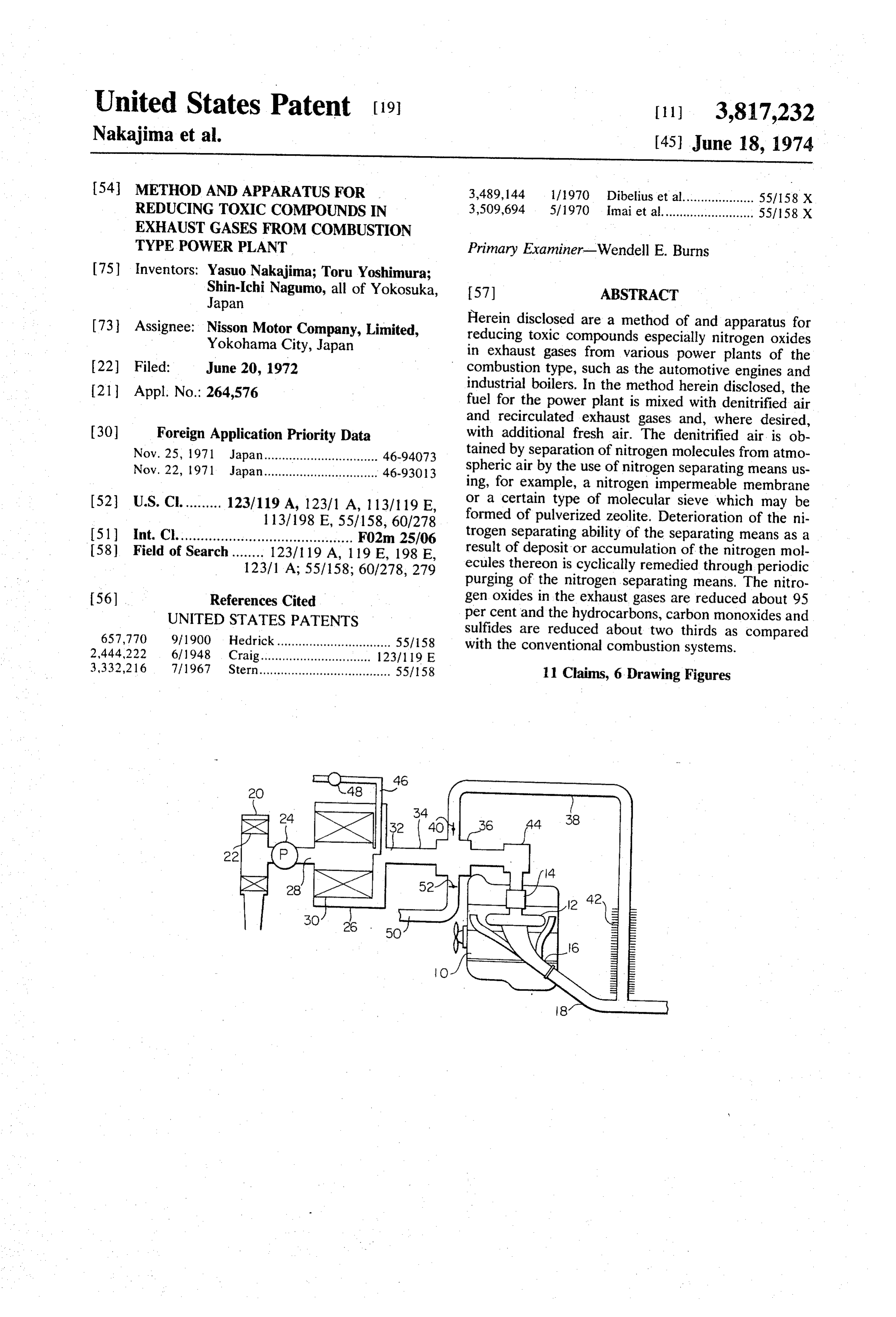
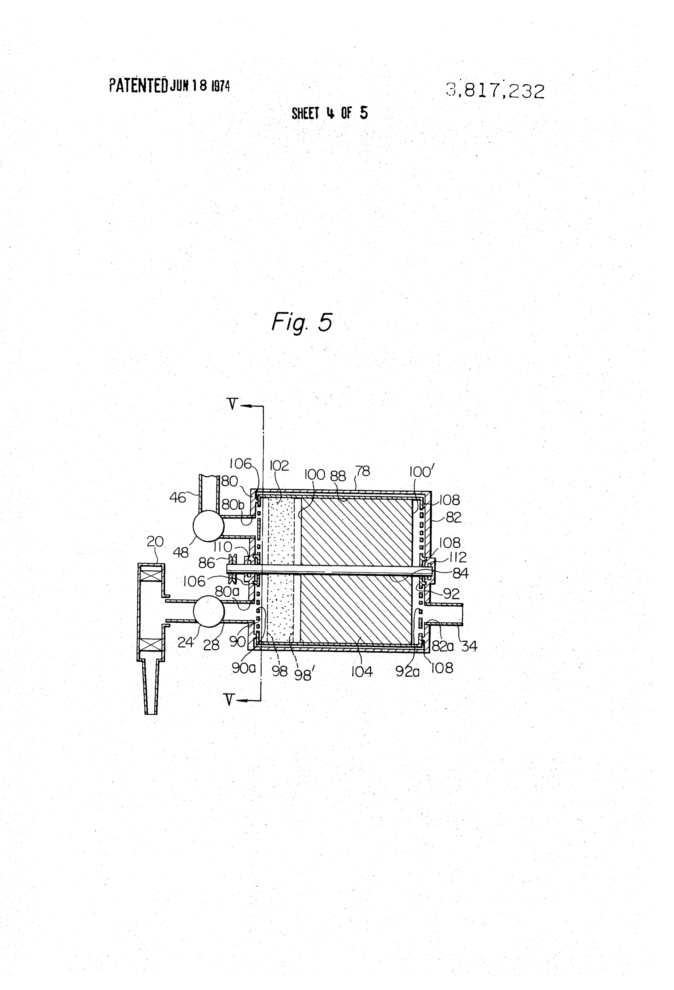
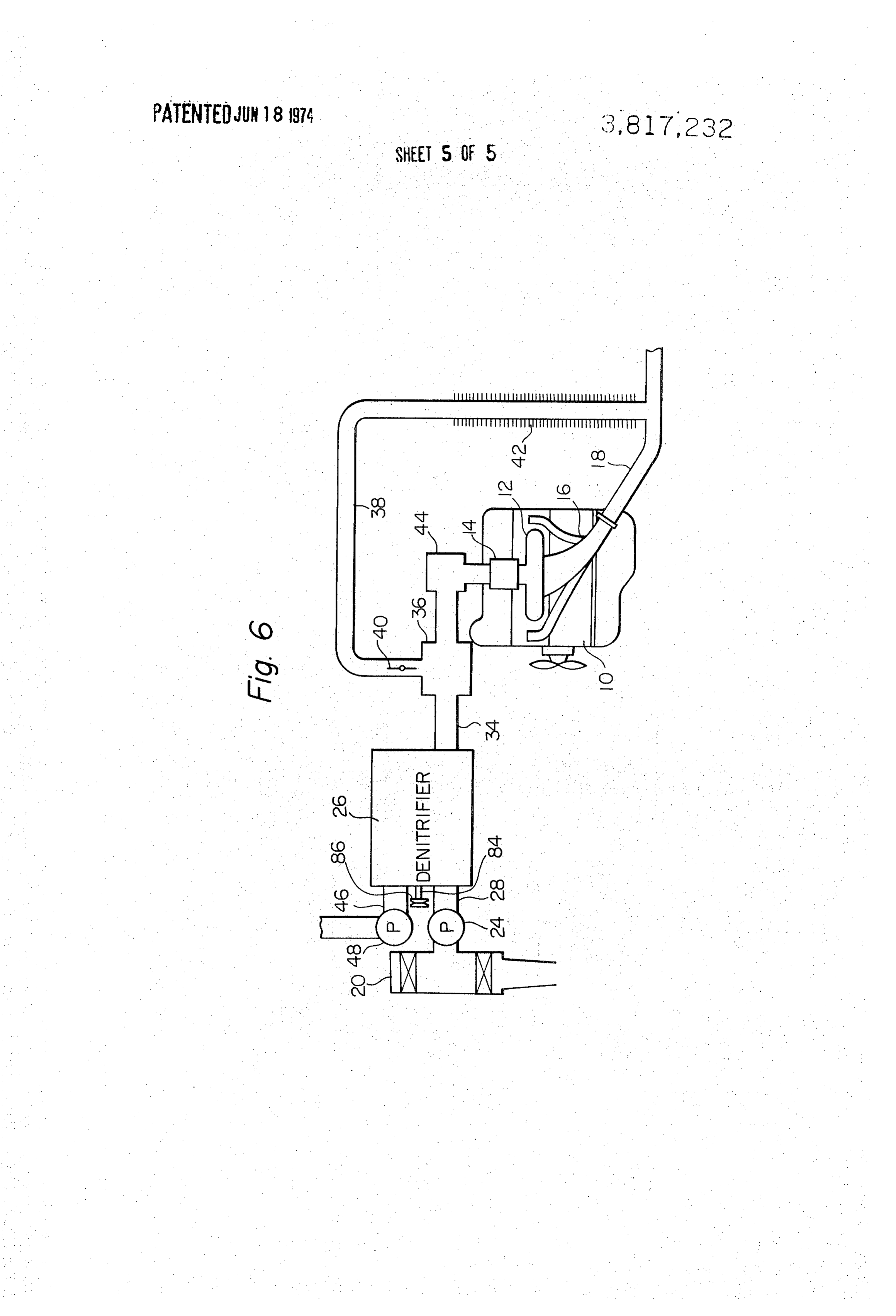
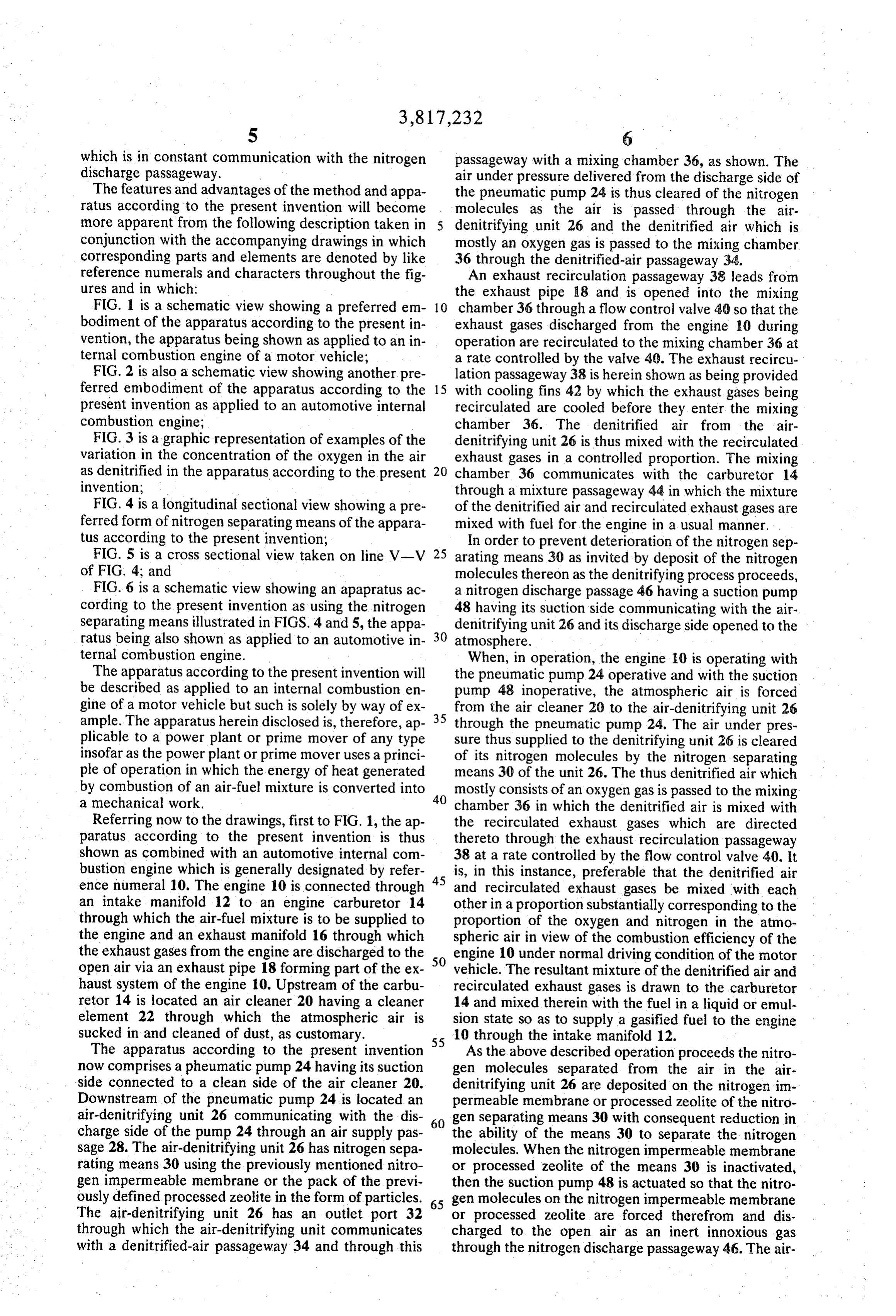
which is in constant communication with the nitrogen passageway with a mixing chamber 36, as shown. The discharge passageway. air under pressure delivered from the discharge side of The features and advantages of the method and appa the pneumatic pump 24 is thus cleared of the nitrogen ratus according to the present invention will become molecules as the air is passed through the air more apparent from the following description taken in denitrifying unit 26 and the denitrified air which is conjunction with the accompanying drawings in which mostly an oxygen gas is passed to the mixing chamber corresponding parts and elements are denoted by like 36 through the denitrified-air passageway 34. reference numerals and characters throughout the fig An exhaust recirculation passageway 38 leads from ures and in which: the exhaust pipe 18 and is opened into the mixing FIG. 1 is a schematic view showing a preferred em 10 chamber 36 through a flow control valve 40 so that the bodiment of the apparatus according to the present in exhaust gases discharged from the engine 10 during vention, the apparatus being shown as applied to an in operation are recirculated to the mixing chamber 36 at ternal combustion engine of a motor vehicle; a rate controlled by the valve 40. The exhaust recircu FIG. 2 is also a schematic view showing another pre lation passageway 38 is herein shown as being provided ferred embodiment of the apparatus according to the 15 with cooling fins 42 by which the exhaust gases being present invention as applied to an automotive internal recirculated are cooled before they enter the mixing combustion engine; chamber 36. The denitrified air from the air FIG. 3 is a graphic representation of examples of the denitrifying unit 26 is thus mixed with the recirculated variation in the concentration of the oxygen in the air exhaust gases in a controlled proportion. The mixing as denitrified in the apparatus according to the present 20 chamber 36 communicates with the carburetor 14 invention; through a mixture passageway 44 in which the mixture FIG. 4 is a longitudinal sectional view showing a pre of the denitrified air and recirculated exhaust gases are ferred form of nitrogen separating means of the appara mixed with fuel for the engine in a usual manner. tus according to the present invention; In order to prevent deterioration of the nitrogen sep FIG. 5 is a cross sectional view taken on line V-V 25 arating means 30 as invited by deposit of the nitrogen of FIG. 4; and molecules thereon as the denitrifying process proceeds, FIG. 6 is a schematic view showing an apapratus ac a nitrogen discharge passage 46 having a suction pump cording to the present invention as using the nitrogen 48 having its suction side communicating with the air separating means illustrated in FIGS. 4 and 5, the appa denitrifying unit 26 and its discharge side opened to the ratus being also shown as applied to an automotive in 30 atmosphere.
ternal combustion engine. When, in operation, the engine 0 is operating with The apparatus according to the present invention will the pneumatic pump 24 operative and with the suction be described as applied to an internal combustion en pump 48 inoperative, the atmospheric air is forced gine of a motor vehicle but such is solely by way of ex 35 from the air cleaner 20 to the air-denitrifying unit 26 ample. The apparatus herein disclosed is, therefore, ap through the pneumatic pump 24. The air under pres plicable to a power plant or prime mover of any type sure thus supplied to the denitrifying unit 26 is cleared insofar as the power plant or prime mover uses a princi of its nitrogen molecules by the nitrogen separating ple of operation in which the energy of heat generated means 30 of the unit 26. The thus denitrified air which by combustion of an air-fuel mixture is converted into 40 mostly consists of an oxygen gas is passed to the mixing a mechanical work. chamber 36 in which the denitrified air is mixed with Referring now to the drawings, first to FIG. 1, the ap the recirculated exhaust gases which are directed paratus according to the present invention is thus thereto through the exhaust recirculation passageway shown as combined with an automotive internal com 38 at a rate controlled by the flow control valve 40. It bustion engine which is generally designated by refer 45 is, in this instance, preferable that the denitrified air ence numeral 10. The engine 10 is connected through and recirculated exhaust gases be mixed with each an intake manifold 12 to an engine carburetor 14 other in a proportion substantially corresponding to the through which the air-fuel mixture is to be supplied to proportion of the oxygen and nitrogen in the atmo the engine and an exhaust manifold 16 through which spheric air in view of the combustion efficiency of the the exhaust gases from the engine are discharged to the engine 10 under normal driving condition of the motor open air via an exhaust pipe 18 forming part of the ex 50 vehicle. The resultant mixture of the denitrified air and haust system of the engine 10. Upstream of the carbu recirculated exhaust gases is drawn to the carburetor retor 14 is located an air cleaner 20 having a cleaner 14 and mixed therein with the fuel in a liquid or emul element 22 through which the atmospheric air is sion state so as to supply a gasified fuel to the engine sucked in and cleaned of dust, as customary. 10 through the intake manifold 12. The apparatus according to the present invention 55 As the above described operation proceeds the nitro now comprises a pheumatic pump 24 having its suction gen molecules separated from the air in the air side connected to a clean side of the air cleaner 20. denitrifying unit 26 are deposited on the nitrogen im Downstream of the pneumatic pump 24 is located an permeable membrane or processed zeolite of the nitro air-denitrifying unit 26 communicating with the dis 60 gen separating means 30 with consequent reduction in charge side of the pump 24 through an air supply pas the ability of the means 30 to separate the nitrogen sage 28. The air-denitrifying unit 26 has nitrogen sepa molecules. When the nitrogen impermeable membrane rating means 30 using the previously mentioned nitro or processed zeolite of the means 30 is inactivated, gen impermeable membrane or the pack of the previ then the suction pump 48 is actuated so that the nitro ously defined processed zeolite in the form of particles. gen molecules on the nitrogen impermeable membrane The air-denitrifying unit 26 has an outlet port 32 65 or processed zeolite are forced therefrom and dis through which the air-denitrifying unit communicates charged to the open air as an inert innoxious gas with a denitrified-air passageway 34 and through this through the nitrogen discharge passageway 46. The air
Page 10
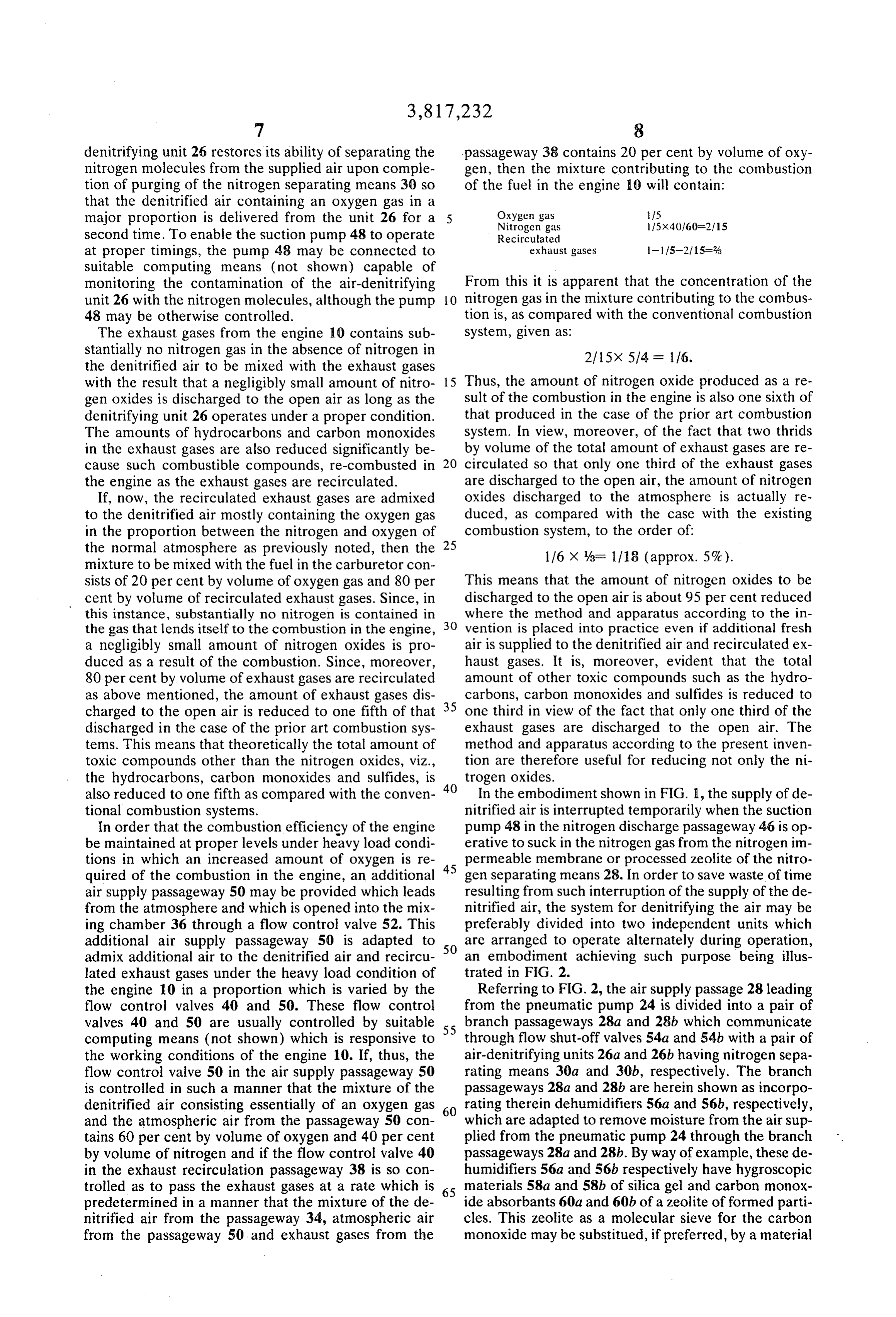
denitrifying unit 26 restores its ability of separating the passageway 38 contains 20 per cent by volume of oxy nitrogen molecules from the supplied air upon comple gen, then the mixture contributing to the combustion tion of purging of the nitrogen separating means 30 so of the fuel in the engine 10 will contain: that the denitrified air containing an oxygen gas in a major proportion is delivered from the unit 26 for a Oxygen gas 15
second time. To enable the suction pump 48 to operate Recirculated at proper timings, the pump 4.8 may be connected to exhaust gases -115-21 S=% suitable computing means (not shown) capable of monitoring the contamination of the air-denitrifying From this it is apparent that the concentration of the unit 26 with the nitrogen molecules, although the pump O nitrogen gas in the mixture contributing to the combus 48 may be otherwise controlled. tion is, as compared with the conventional combustion The exhaust gases from the engine 10 contains sub System, given as:
stantially no nitrogen gas in the absence of nitrogen in 2115X 5/4 = 1/6. the denitrified air to be mixed with the exhaust gases with the result that a negligibly small amount of nitro 5 Thus, the amount of nitrogen oxide produced as a re gen oxides is discharged to the open air as long as the sult of the combustion in the engine is also one sixth of denitrifying unit 26 operates under a proper condition. that produced in the case of the prior art combustion The amounts of hydrocarbons and carbon monoxides system. In view, moreover, of the fact that two thrids in the exhaust gases are also reduced significantly be by volume of the total amount of exhaust gases are re cause such combustible compounds, re-combusted in 20 circulated so that only one third of the exhaust gases the engine as the exhaust gases are recirculated. are discharged to the open air, the amount of nitrogen If, now, the recirculated exhaust gases are admixed oxides discharged to the atmosphere is actually re to the denitrified air mostly containing the oxygen gas duced, as compared with the case with the existing in the proportion between the nitrogen and oxygen of combustion system, to the order of: the normal atmosphere as previously noted, then the 25 116 X %= 1/18 (approx. 5%). mixture to be mixed with the fuel in the carburetor con sists of 20 per cent by volume of oxygen gas and 80 per This means that the amount of nitrogen oxides to be cent by volume of recirculated exhaust gases. Since, in discharged to the open air is about 95 per cent reduced this instance, substantially no nitrogen is contained in where the method and apparatus according to the in the gas that lends itself to the combustion in the engine, 30 vention is placed into practice even if additional fresh a negligibly small amount of nitrogen oxides is pro air is supplied to the denitrified air and recirculated ex duced as a result of the combustion. Since, moreover, haust gases. It is, moreover, evident that the total 80 per cent by volume of exhaust gases are recirculated amount of other toxic compounds such as the hydro as above mentioned, the amount of exhaust gases dis 35 carbons, carbon monoxides and sulfides is reduced to charged to the open air is reduced to one fifth of that one third in view of the fact that only one third of the discharged in the case of the prior art combustion sys exhaust gases are discharged to the open air. The tems. This means that theoretically the total amount of method and apparatus according to the present inven toxic compounds other than the nitrogen oxides, viz., tion are therefore useful for reducing not only the ni the hydrocarbons, carbon monoxides and sulfides, is 40 trogen oxides.
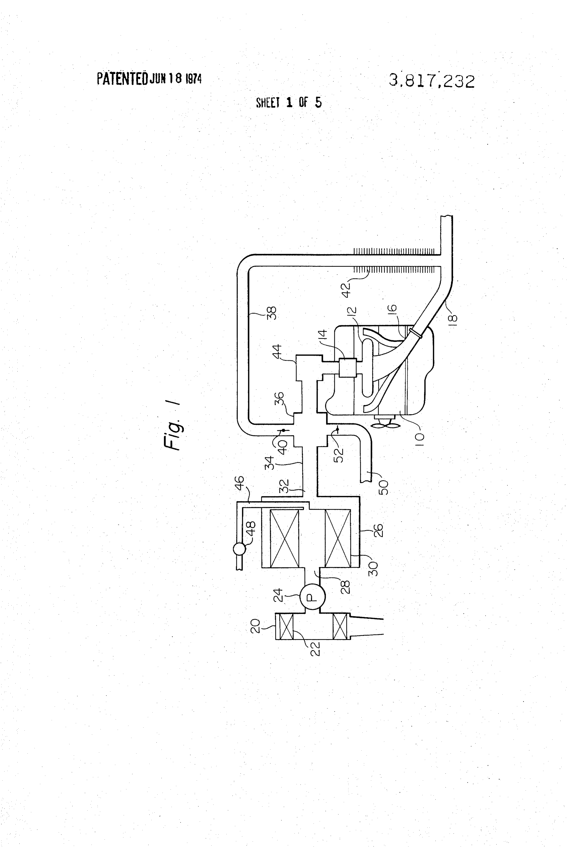
also reduced to one fifth as compared with the conven In the embodiment shown in FIG. 1, the supply of de tional combustion systems. nitrified air is interrupted temporarily when the suction In order that the combustion efficiency of the engine pump 48 in the nitrogen discharge passageway 46 is op be maintained at proper levels under heavy load condi erative to suck in the nitrogen gas from the nitrogen im tions in which an increased amount of oxygen is re 45 permeable membrane or processed zeolite of the nitro quired of the combustion in the engine, an additional gen separating means 28. In order to save waste of time air supply passageway 50 may be provided which leads resulting from such interruption of the supply of the de from the atmosphere and which is opened into the mix nitrified air, the system for denitrifying the air may be ing chamber 36 through a flow control valve 52. This preferably divided into two independent units which additional air supply passageway 50 is adapted to are arranged to operate alternately during operation, admix additional air to the denitrified air and recircu 50 an embodiment achieving such purpose being illus lated exhaust gases under the heavy load condition of trated in FIG. 2.
the engine 10 in a proportion which is varied by the Referring to FIG. 2, the air supply passage 28 leading flow control valves 40 and 50. These flow control from the pneumatic pump 24 is divided into a pair of valves 40 and 50 are usually controlled by suitable 55 branch passageways 28a and 28b which communicate computing means (not shown) which is responsive to through flow shut-off valves 54a and 54b with a pair of the working conditions of the engine 10. If, thus, the air-denitrifying units 26a and 26b having nitrogen sepa flow control valve 50 in the air supply passageway 50 rating means 30a and 30b, respectively. The branch is controlled in such a manner that the mixture of the passageways 28a and 28b are herein shown as incorpo denitrified air consisting essentially of an oxygen gas 60 rating therein dehumidifiers 56a and 56b, respectively, and the atmospheric air from the passageway 50 con which are adapted to remove moisture from the air sup tains 60 per cent by volume of oxygen and 40 per cent plied from the pneumatic pump 24 through the branch by volume of nitrogen and if the flow control valve 40 passageways 28a and 28b. By way of example, these de in the exhaust recirculation passageway 38 is so con humidifiers 56a and 56b respectively have hygroscopic trolled as to pass the exhaust gases at a rate which is 65 materials 58a and 58b of silica gel and carbon monox predetermined in a manner that the mixture of the de ide absorbants 60a and 60b of a zeolite of formed parti nitrified air from the passageway 34, atmospheric air cles. This zeolite as a molecular sieve for the carbon from the passageway 50 and exhaust gases from the monoxide may be substitued, if preferred, by a material
Page 11
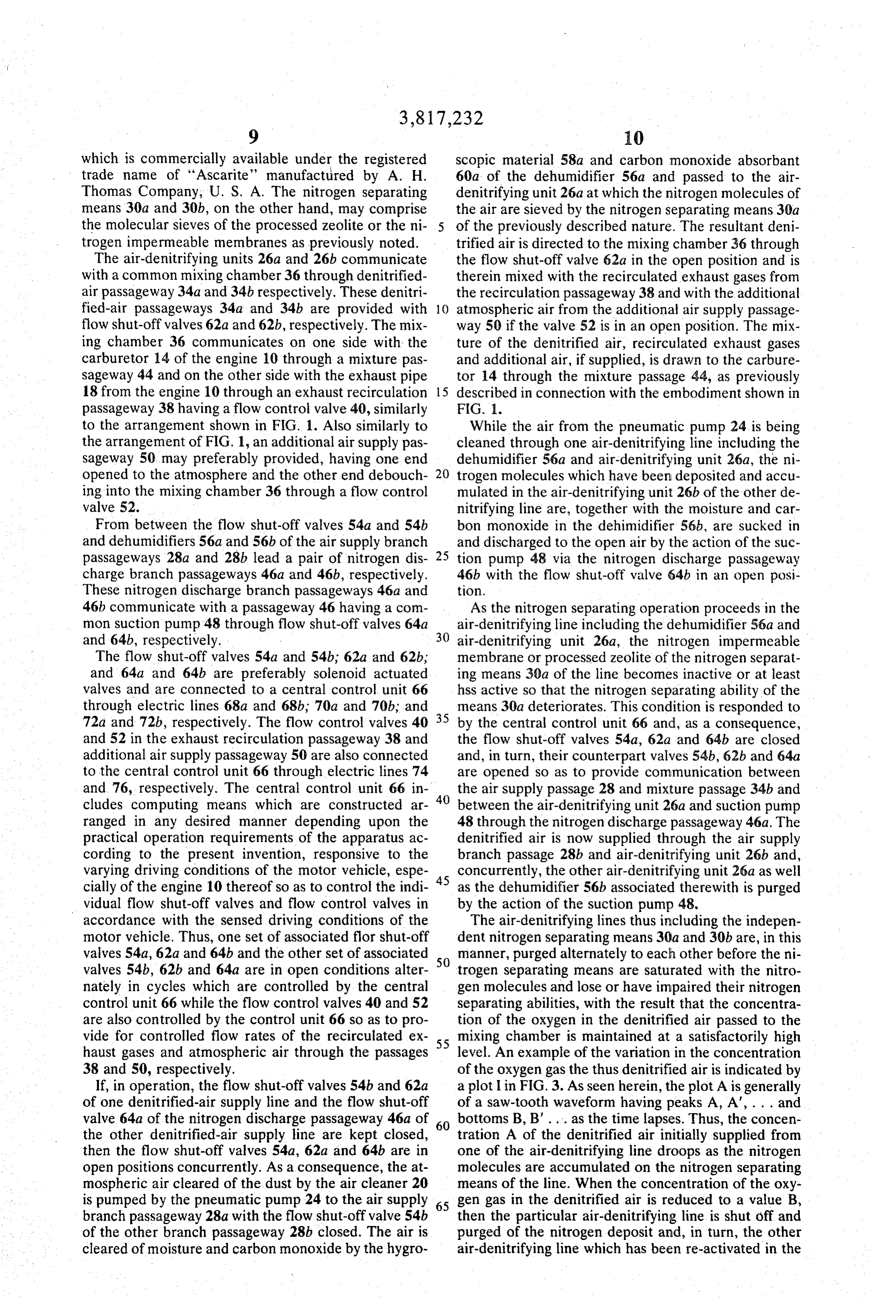
which is commercially available under the registered scopic material 58a and carbon monoxide absorbant trade name of "Ascarite' manufactured by A. H. 60a of the dehumidifier 56a and passed to the air Thomas Company, U. S. A. The nitrogen separating denitrifying unit 26a at which the nitrogen molecules of means 30a and 30b, on the other hand, may comprise the air are sieved by the nitrogen separating means 30a the molecular sieves of the processed zeolite or the ni of the previously described nature. The resultant deni trogen impermeable membranes as previously noted. trified air is directed to the mixing chamber 36 through The air-denitrifying units 26a and 26b communicate the flow shut-off valve 62a in the open position and is with a common mixing chamber 36 through denitrified therein mixed with the recirculated exhaust gases from air passageway 34a and 34b respectively. These denitri the recirculation passageway 38 and with the additional fied-air passageways 34a and 34b are provided with 10 atmospheric air from the additional air supply passage flow shut-off valves 62a and 62b, respectively. The mix way 50 if the valve 52 is in an open position. The mix ing chamber 36 communicates on one side with the ture of the denitrified air, recirculated exhaust gases carburetor 14 of the engine 10 through a mixture pas and additional air, if supplied, is drawn to the carbure sageway 44 and on the other side with the exhaust pipe tor 14 through the mixture passage 44, as previously 18 from the engine 10 through an exhaust recirculation 15 described in connection with the embodiment shown in passageway 38 having a flow control valve 40, similarly FIG. I.
to the arrangement shown in FIG. 1. Also similarly to While the air from the pneumatic pump 24 is being the arrangement of FIG. 1, an additional air supply pas cleaned through one air-denitrifying line including the Sageway 50 may preferably provided, having one end dehumidifier 56a and air-denitrifying unit 26a, the ni opened to the atmosphere and the other end debouch 20 trogen molecules which have been deposited and accu ing into the mixing chamber 36 through a flow control mulated in the air-denitrifying unit 26b of the other de valve 52. nitrifying line are, together with the moisture and car From between the flow shut-off valves 54a and 54b bon monoxide in the dehimidifier 56b, are sucked in and dehumidifiers 56a and 56b of the air supply branch 25 and discharged to the open air by the action of the suc passageways 28a and 28b lead a pair of nitrogen dis tion pump 48 via the nitrogen discharge passageway charge branch passageways 46a and 46b, respectively. 46b with the flow shut-off valve 64b in an open posi These nitrogen discharge branch passageways 46a and tion.
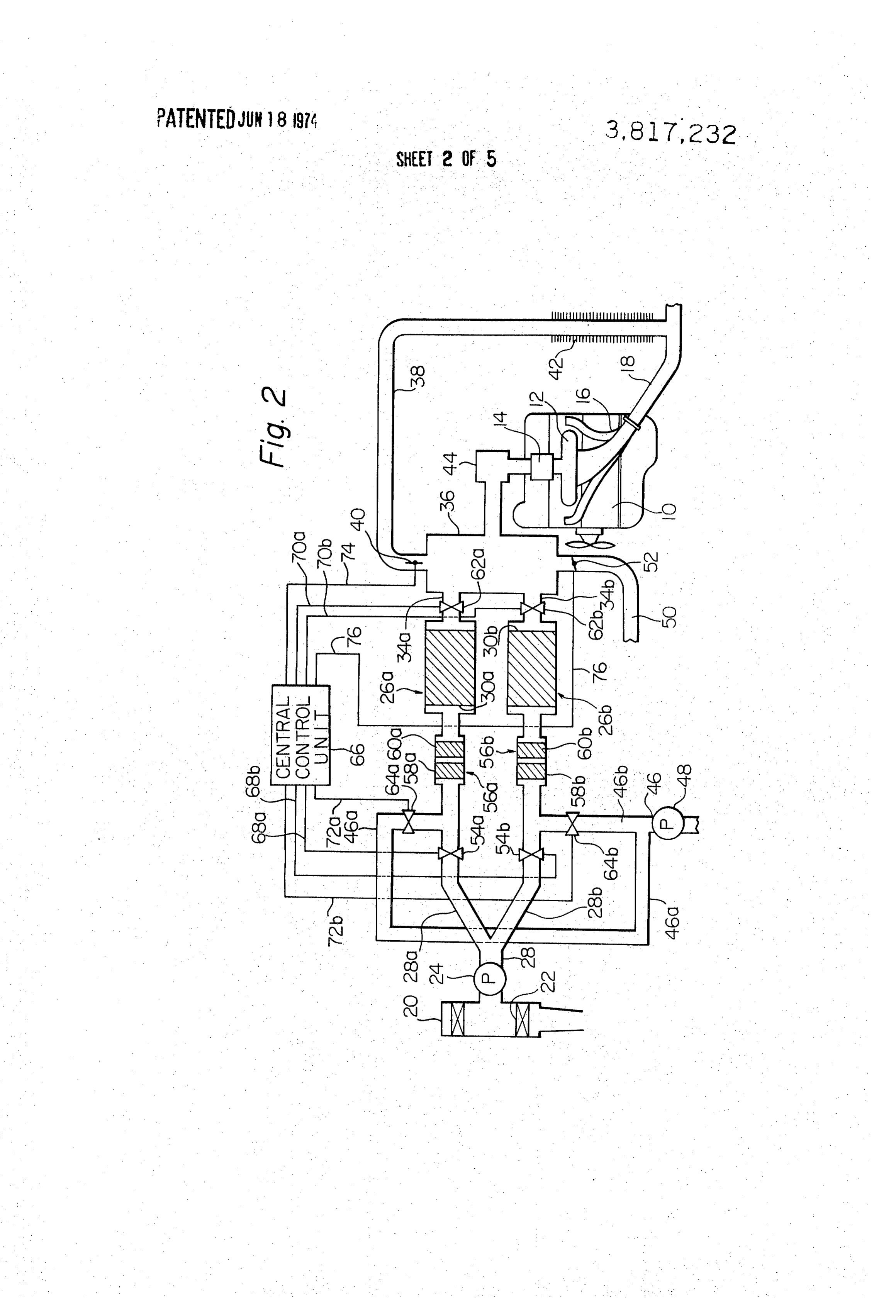
46b communicate with a passageway 46 having a com As the nitrogen separating operation proceeds in the mon suction pump 48 through flow shut-off valves 64a air-denitrifying line including the dehumidifier 56a and and 64b, respectively. 30 air-denitrifying unit 26a, the nitrogen impermeable The flow shut-off valves 54a and 54b, 62a and 62b; membrane or processed zeolite of the nitrogen separat and 64a and 64b are preferably solenoid actuated ing means 30a of the line becomes inactive or at least valves and are connected to a central control unit 66 hss active so that the nitrogen separating ability of the through electric lines 68a and 68b, 70a and 70b, and 35 means 30a deteriorates. This condition is responded to 72a and 72b, respectively. The flow control valves 40 by the central control unit 66 and, as a consequence, and 52 in the exhaust recirculation passageway 38 and the flow shut-off valves 54a, 62a and 64b are closed additional air supply passageway 50 are also connected and, in turn, their counterpart valves 54b, 62b and 64a to the central control unit 66 through electric lines 74 are opened so as to provide communication between and 76, respectively. The central control unit 66 in 40 the air supply passage 28 and mixture passage 34b and cludes computing means which are constructed ar between the air-denitrifying unit 26a and suction pump ranged in any desired manner depending upon the 48 through the nitrogen discharge passageway 46a. The practical operation requirements of the apparatus ac denitrified air is now supplied through the air supply cording to the present invention, responsive to the branch passage 28b and air-denitrifying unit 26b and, varying driving conditions of the motor vehicle, espe 45 concurrently, the other air-denitrifying unit 26a as well cially of the engine 10 thereof so as to control the indi as the dehumidifier 56b associated therewith is purged vidual flow shut-off valves and flow control valves in by the action of the suction pump 48. accordance with the sensed driving conditions of the The air-denitrifying lines thus including the indepen motor vehicle. Thus, one set of associated for shut-off dent nitrogen separating means 30a and 30b are, in this valves 54a, 62a and 64b and the other set of associated 50 manner, purged alternately to each other before the ni valves 54b, 62b and 64a are in open conditions alter trogen separating means are saturated with the nitro nately in cycles which are controlled by the central gen molecules and lose or have impaired their nitrogen control unit 66 while the flow control valves 40 and 52 separating abilities, with the result that the concentra are also controlled by the control unit 66 so as to pro tion of the oxygen in the denitrified air passed to the vide for controlled flow rates of the recirculated ex mixing chamber is maintained at a satisfactorily high haust gases and atmospheric air through the passages 55 level. An example of the variation in the concentration 38 and 50, respectively. of the oxygen gas the thus denitrified air is indicated by If, in operation, the flow shut-off valves 54b and 62a a plot I in FIG. 3. As seen herein, the plot A is generally of one denitrified-air supply line and the flow shut-off of a saw-tooth waveform having peaks A, A', . . . and valve 64a of the nitrogen discharge passageway 46a of 60 bottoms B, B' ... as the time lapses. Thus, the concen the other denitrified-air supply line are kept closed, tration A of the denitrified air initially supplied from then the flow shut-off valves 54a, 62a and 64b are in one of the air-denitrifying line droops as the nitrogen open positions concurrently. As a consequence, the at molecules are accumulated on the nitrogen separating mospheric air cleared of the dust by the air cleaner 20 means of the line. When the concentration of the oxy is pumped by the pneumatic pump 24 to the air supply 65 gen gas in the denitrified air is reduced to a value B, branch passageway 28a with the flow shut-off valve 54b then the particular air-denitrifying line is shut off and of the other branch passageway 28b closed. The air is purged of the nitrogen deposit and, in turn, the other cleared of moisture and carbon monoxide by the hygro air-denitrifying line which has been re-activated in the
Page 12
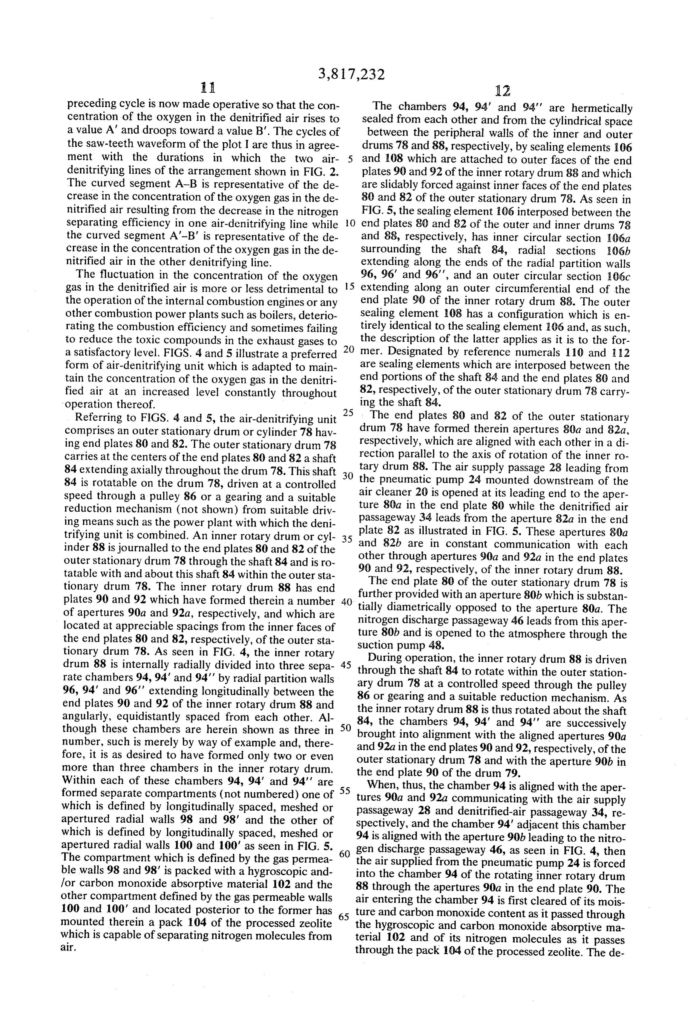
A. 12 preceding cycle is now made operative so that the con The chambers 94, 94' and 94' are hermetically centration of the oxygen in the denitrified air rises to sealed from each other and from the cylindrical space a value A" and droops toward a value B'. The cycles of between the peripheral walls of the inner and outer the saw-teeth waveform of the plot I are thus in agree drums 78 and 88, respectively, by sealing elements 106 ment with the durations in which the two air and 108 which are attached to outer faces of the end denitrifying lines of the arrangement shown in FIG. 2. plates 90 and 92 of the inner rotary drum 88 and which The curved segment A-B is representative of the de are slidably forced against inner faces of the end plates crease in the concentration of the oxygen gas in the de 80 and 82 of the outer stationary drum 78. As seen in nitrified air resulting from the decrease in the nitrogen FIG. 5, the sealing element 106 interposed between the separating efficiency in one air-denitrifying line while O end plates 80 and 82 of the outer and inner drums 78 the curved segment A-B' is representative of the de and 88, respectively, has inner circular section 06a crease in the concentration of the oxygen gas in the de surrounding the shaft 84, radial sections 06b nitrified air in the other denitrifying line. extending along the ends of the radial partition walls The fluctuation in the concentration of the oxygen 15 96, 96' and 96', and an outer circular section 06c gas in the denitrified air is more or less detrimental to extending along an outer circumferential end of the the operation of the internal combustion engines or any end plate 90 of the inner rotary drum 88. The outer other combustion power plants such as boilers, deterio sealing element 108 has a configuration which is en rating the combustion efficiency and sometimes failing tirely identical to the sealing element 06 and, as such, to reduce the toxic compounds in the exhaust gases to 20 the description of the latter applies as it is to the for a satisfactory level. FIGS. 4 and 5 illustrate a preferred mer. Designated by reference numerals 110 and 12 form of air-denitrifying unit which is adapted to main are sealing elements which are interposed between the tain the concentration of the oxygen gas in the denitri end portions of the shaft 84 and the end plates 80 and fied air at an increased level constantly throughout 82, respectively, of the outer stationary drum 78 carry operation thereof. ing the shaft 84.
Referring to FIGS. 4 and 5, the air-denitrifying unit 25 The end plates 80 and 82 of the outer stationary comprises an outer stationary drum or cylinder 78 hav drum 78 have formed therein apertures 80a and 82a, ing end plates 80 and 82. The outer stationary drum 78 respectively, which are aligned with each other in a di carries at the centers of the end plates 80 and 82 a shaft rection parallel to the axis of rotation of the inner ro 84 extending axially throughout the drum 78. This shaft 30 tary drum 88. The air supply passage 28 leading from 84 is rotatable on the drum 78, driven at a controlled the pneumatic pump 24 mounted downstream of the speed through a pulley 86 or a gearing and a suitable air cleaner 20 is opened at its leading end to the aper reduction mechanism (not shown) from suitable driv ture 80a in the end plate 80 while the denitrified air ing means such as the power plant with which the deni passageway 34 leads from the aperture 82a in the end trifying unit is combined. An inner rotary drum or cyl 35 plate and 82 as illustrated in FIG. 5. These apertures 80a 82b are in constant communication with each inder 88 is journalled to the end plates 80 and 82 of the other through apertures 90a and 92a in the end plates outer stationary drum 78 through the shaft 84 and is ro 90 and 92, respectively, of the inner rotary drum 88. tatable with and about this shaft 84 within the outer sta
The end plate 80 tionary drum 78. The inner rotary drum 88 has end further provided with an apertureof the outer stationary drum 78 is plates 90 and 92 which have formed therein a number 40 tially diametrically opposed to the80baperturewhich is substan 80a. The of apertures 90a and 92a, respectively, and which are nitrogen discharge passageway 46 leads from this located at appreciable spacings from the inner faces of ture 80b and is opened to the atmosphere throughaper the the end plates 80 and 82, respectively, of the outer sta tionary drum 78. As seen in FIG. 4, the inner rotary suction pump 48.
During operation, the inner rotary drum 88 is driven drum 88 is internally radially divided into three sepa 45 through rate chambers 94, 94' and 94' by radial partition walls ary drumthe78shaft 84 to rotate within the outer station 96, 94' and 96' extending longitudinally between the 86 or gearing and controlled at a speed through the pulley end plates 90 and 92 of the inner rotary drum 88 and the inner rotary drum 88 is thus rotated mechanism. a suitable reduction As about the shaft angularly, equidistantly spaced from each other. Al 84, the chambers 94, 94' and 94' are successively though these chambers are herein shown as three in 50 brought number, such is merely by way of example and, there and 92a ininto alignment with the aligned apertures 90a fore, it is as desired to have formed only two or even outer stationaryenddrum the plates 90 and 92, respectively, of the more than three chambers in the inner rotary drum. the end plate 90 of the78drum and with the aperture 90b in
Within each of these chambers 94, 94' and 94' are 55 When, thus, the chamber 94 is aligned with the aper formed separate compartments (not numbered) one of tures 90a and 92a communicating with the air supply which is defined by longitudinally spaced, meshed or passageway 28 and denitrified-air passageway 34, re apertured radial walls 98 and 98' and the other of spectively, and the chamber 94' adjacent this chamber which is defined by longitudinally spaced, meshed or 94 is aligned with the aperture 90b leading to the nitro apertured radial walls 100 and 100' as seen in FIG. 5. gen discharge passageway 46, as seen in FIG. 4, then The compartment which is defined by the gas permea the air supplied from the pneumatic pump 24 is forced ble walls 98 and 98' is packed with a hygroscopic and into the chamber 94 of the rotating inner rotary drum for carbon monoxide absorptive material 102 and the 88 through the apertures 90a in the end plate 90. The other compartment defined by the gas permeable walls air entering the chamber 94 is first cleared of its mois 100 and 100' and located posterior to the former has ture and carbon monoxide content as it passed through mounted therein a pack 104 of the processed zeolite 65 the hygroscopic and carbon monoxide absorptive ma which is capable of separating nitrogen molecules from terial 102 and of its nitrogen molecules as it passes
through the pack 104 of the processed zeolite. The de
Page 13
nitrified air obtained in this manner is discharged to the mixing chamber 36 leading to the carburetor 14 denitrified-air passageway 34 through the apertures 92a in the end plate p of the inner rotary drum 88 be throughing with the mixture passageway 44 and communicat the exhaust pipe 18 through the exhaust recir fore the chamber 94 is brought out of alignment with culation passageway 38. The operation of the arrange the aperture 82a in the end plate 90 of the outer sta ment herein shown in essentially similar to that of the tionary drum 78. While this occurs, the chamber 94' arrangement shown in FIG. 1 except for the operation aligned with the aperture 80b leading to the suction of the air-denitrifying unit 26 the operation of which pump 48 is subject to suction so that the nitrogen mole has been described.
cules as well as the moisture and carbon monoxide de posited in the chamber 94' are released from the pack 10 that the now
It will be appreciated from the above description method and apparatus according to the present 104 and moisture and carbon monoxide absorptive ma invention are useful in minimizing the concentration of terial 102 in the chamber 94' and are forced out of the the nitrogen oxides in the exhaust gases from various nitrogen discharge passageway 46. The chamber 94' is power plants and, at the same time, reducing the other in this manner purged of the nitrogen and carbon mon toxic compounds such as the hydrocarbons, carbon oxide deposits by the time at which the chamber 94' is 15 monoxides and sulfides with use of a simple construc brought out of alignment with the aperture 80b in the tion. No separate or independent apparatus is required end plate 80 of the outer stationary drum 78. Then, the to reduce the hydrocarbons, carbon monoxides and chamber 94' is aligned with the apertures 80a and 82a sulfides in the exhaust gases, in contrast to the prior art so as to absorb the nitrogen molecules and carbon techniques in which these toxic compounds are re monoxide therein while the chamber 94 is purged of 20 duced by the use an apparatus which is independent the accumulated nitrogen molecules and carbon mon oxide. The chambers 94, 94' and 94' are thus cycli from the apparatus to reduce the nitrogen oxides. The cally brought into the positions to denitrify the air and expectedand method apparatus herein disclosed are, therefore, to be purged of the nitrogen deposit as the inner rotary the air pollution problemscontribute to significantly caused by to the solution of the operation of drum 88 is driven to rotate within the outer stationary 25 various power plants such as the automotive internal drum 78. The cycle of operation in which the individual combustion engines and industrial boilers. The types of chambers 94, 94' and 94' are aligned with the aper tures 80a and 80b in the end plate 80, viz., with the pas the molecular sieves as named in this specification are sageways 28 and 46 can be selected arbitarily through desired type ofofnitrogen not limitative the present invention and, as such, any separating means will find ap selection of the number of the chambers to be formed 30 plication in the method and apparatus according to the in the inner rotary drum 88 and/or the speed of rotation present invention.
of the rotary drum 88. What is claimed is:
Through use of the air-denitrifying unit having the 1. A method for minimizing the content of nitrogen above described construction and operation, the con oxides in exhaust gases from a combustion power plant centration of the oxygen gas in the denitrified air sup 35 comprising the steps of passing through nitrogen sepa plied therefrom is maintained at a satisfactorily ele rating means a stream of air for the power plant for sub vated level because the plurality of nitrogen separating means constituting the denitrifying unit are cleaned in stantially denitrigying the air; adding to the denitrified air a portion of exhaust gases from the power plant for sufficiently minute cycles before the separating means diluting the denitirified air; and mixing the diluted air lose or have deteriorated their ability of separating the 40 with a fuel for producing a combustible mixture for the nitrogen molecules from the air passed therethrough. power plant.
An example of the variation in the concentration of the 2. A method as claimed in claim 1 further comprising oxygen gas in the denitrified air obtained by the use of a step of adding to the diluted air the atmospheric air the unit of such character is indicated by a plot II in 45 during a condition in which the power plant is operated FIG. 3. This plot II is generally of a saw-tooth waveform with a relatively heavy load.
which is similar to the plot indicating the denitrifying 3. An apparatus for separating nitrogen from air characteristics of the denitrifying unit shown in FIG. 2. comprising:
The plot II, however, shows that the concentration of a rotary drum having elongated chambers for the pas the oxygen gas in the denitrified air is maintained at 50 sage of air therethrough, each extending parallel to high levels throughout the operation of the denitrifying the axis of rotation of said rotary drum from one unit although such concentration fluctuates to an ap sector in one end of said rotary drum to the oppo preciable degree as from point C to D and from C to site sector in the opposite end of said rotary drum D'. It is, in this instance, apparent that the point C or and containing therein a pack of nitrogen imper C' is indicative of the concentration of the oxygen in meable material;
the denitrified air delivered from one of the chambers 55 a housing within which said rotary drum is mounted, 94, 94' and 94' at the initial stage of its alignment with said housing having respective end plates to the op the apertures 80a and 82a in the end plates 80 and 82 posite ends of said rotary drum, one of said end of the outer stationary drum while the point D or D' is plates having formed therein first and second aper indicative of the concentration of the oxygen delivered, tures which are substantially opposed to each other from that particular chamber at the final stage of its 60 through the axis of rotation of said rotary drum, the alignment with these apertures 80a and 82a. other end plate having formed therein a third aper FIG. 6 illustrates an arrangement in which the air ture which is axially aligned to said first aperture denitrifying unit 26 having the construction shown in along the axis of said rotary drum; FIGS. 4 and 5 is placed on use with the internal com bustion engine 10 of a motor vehicle, similarly to the 65 sealing means carried by said sectors and sliding on the adjacent end plates of said housing to thereby arrangements shown in FIGS. 1 and 2. As illustrated, seal one from another of said elongated chambers; the denitrified-air passageway 34 is opened into the
Page 14
air supply passage means communicating with said chamber from another, air supply passage means open first aperture for passing air into one of said elon ing in said housing and supplying air under pressure to gated chambers; any one of said elongated chambers as the rotary drum denitrified air passage means communicating with rotates about the axis; denitrified air passage means said third aperture for removing denitrified air opening into said housing and removing denitrified air from said one elongated chamber, and from said any one of said elongated chambers and sup nitrogen discharge passage means communicating plying the denitrified air through said denitrified-air with said second aperture for removing nitrogen passageway to said mixing chamber; and nitrogen dis unable to permeate through said one elongated charge passage means also opening into said housing chamber. 10 and removing nitrogen unable to permeate through 4. An apparatus as claimed in claim 3, wherein said said elongated chambers.
air supply passage means includes a pump for supplying 10. An apparatus as claimed in claim 8, further com the atmospheric air under pressure to said first aper prising an additional air supply passageway leading ture. from the atmosphere and opening at its downstream 5. An apparatus as claimed in claim 4, wherein said 15 end into said mixing chamber and a flow control valve nitrogen discharge passage means includes a suction incorporated in said additional air supply passageway pump to expose said second aperture to the suction. and controlling the supply of atmospheric air to said 6. An apparatus as claimed in claim 5, wherein said mixing chamber.
nitrogen impermeable material includes processed zeo 1. An apparatus for minimizing the content of nitro lite which is in the form of particles. 20 gen oxides in exhaust gases from a combustion power 7. An apparatus as claimed in claim 3, wherein each plant having a carburetor comprising pumping means of said elongated chambers contains a pack of hygro for delivering a stream of an air under pressure, nitro scopic and carbon compound absorptive materials up gen separating means operable to separate nitrogen stream of said pack of nitrogen impermeable material molecules from the air, said stream of air being passed therein. 25 through said nitrogen separating means for substan 8. An apparatus for minimizing the content of nitro tially denitrifying the air, at least one denitrifying air gen oxides in exhaust gases from a combustion power passageway leading from said nitrogen separating plant having a carburetor, comprising nitrogen separat means for passing therethrough the denitrified air de ing means operable to separate nitrogen from air pass livered from said nitrogen separating means, an exhaust ing therethrough to a mixing chamber; a denitrified-air 30 gas recirculation passageway leading from an exhaust passageway leading from an outlet of said nitrogen sep pipe of said power plant for recirculation therethrough arating means and opening to said mixing chamber, an exhaust gases from the power plant, a mixing chamber exhaust gas recirculation passageway leading from an into which said denitrified air passageway and said ex exhaust pipe of opposite power plant and opening to haust gas recirculation passageway are opened at their said mixing chamber; end a mixture passageway lead 35 downstream ends for mixing the denitrified air and re ing from said mixture chamber to said carburetor of the circulated exhaust gases with each other therein, a pas combustion power plant. sageway leading from said passageway to said carbure 9. An apparatus as claimed in claim 8 wherein said tor of said power plant, and additional air supply pas nitrogen separating means comprises a rotary drum sageway leading from the atmosphere and opening at having elongated chambers for air flow therethrough, 40 its downstream end into said mixing chamber and a each extending parallel to the axis of rotation of said flow control valve incorporated in said additional air rotary drum from end to end and containing therein a supply passageway adapted for passing the atmospheric pack of nitrogen impermeable material; a housing air to said mixing chamber during a condition in which within which said rotary drum is mounted, said housing said power plant is operated with a relatively heavy having respective end plates to the oposite ends of said 45 load, said nitrogen separating means comprising at rotary drum, one of said en plates having formed least two sections which are separate from each other therein first and second aperture which are substan and passage means adapted to provide alternate com tially opposed to each other through the axis of rotation munication between said pumping means and said at of said rotary drum, the other end plate having formed least two sections of the nitrogen separating means, a therein a third aperture which is axially aligned to said 50 suction pump, and nitrogen discharge passage means first aperture along the axis of said rotary drum; sealing adapted to provide alternate communication between means between said end plates and the opposed ends said suction pump and said at least two sections of the of said rotary drum, said sealing means being stationary nitrogen separating means to remove nitrogen unable with respect to said rotary drum and sliding on the adja to impermeate through said at least two sections. cent end plates of said housing to seal one elongated 55 sk k ck x: :
Provenance
- Collection
- Cited prior art
- Original PDF
- patentimages.storage.googleapis.com →
- Filed
- 1972-06-20
- Pages
- 14
- Method
- pdftotext (the PDF's own text layer) + pdftoppm 300dpi page scans
- Source
- Google Patents bibliographic record
- Granted
- 1974-06-18
- Inventors
- Y Nakajima; T Yoshimura; S Nagumo; Nissan Motor Co Ltd
- Transcribed from
- patentimages.storage.googleapis.com →