patent · US20160032876A1
Firing-paired Intake Manifold
4 February 2016
Page 1 — bibliographic record
(19) United States (12) Patent Application Publication (10) Pub. No.: US 2016/0032876 A1
Hollinger (43) Pub. Date: Feb. 4, 2016 (54) FRING-PARED INTAKE MANFOLD Publication Classification
(71) Applicant: Ted Hollinger, Algona, IA (US) (51) Int. Cl.
(72) Inventor: Ted Hollinger, Algona, IA (US) FO2B 43/10 (2006.01)
(21) Appl. No.: 14/656,411 CPC ....... F02M 35/10216 (2013.01); F02M 35/104
(22) Filed: Mar 12, 2015 35/1015 (2013.01); F02B 43/10 (2013.01)
Related U.S. Application Data The disclosed apparatus, Systems and methods relate to an intake manifold for use in internal combustion engines which (60) Provisional application No. 61/951,612, filed on Mar. pairs cylinders together so as to allow the sharing of air and 12, 2014. fuel to improve efficiency and power.
Page 2
Drawing sheet — no readable text.
Page 3
Drawing sheet — no readable text.
Page 4
Drawing sheet — no readable text.
Page 5
Drawing sheet — no readable text.
Page 6
Drawing sheet — no readable text.
Page 7
Drawing sheet — no readable text.
Page 8
Drawing sheet — no readable text.
Page 9
Patent Application Publication Feb. 4, 2016 Sheet 8 of 9 US 2016/0032876 A1 firing order 1842&3?é. 18 degr:cs per divisic:
A grisks Poseitriji
Fis: 3 rue in 4 First this Sue knis First li; Suetiris Fue: ht
Fie: in 3 Fuel inj4 Fissliais fuelia; a & init
Series
Aliettos
Page 10
Patent Application Publication Feb. 4, 2016 Sheet 9 of 9 US 2016/0032876 A1
i:iig order 1543,638. 39 degrees per divisioi, fisiirection 3.3 m3&c,5ff3&cgsfjivision
Chiraosition 2x2.5 degree &as algal : .88.9888.i.
gasition
Fis in 1 eili; 2
Fugins
Fusitni.
Fusii
Fueir 8
A: Risco:
fter
Fuef En;3
Fassi 4
Fuse: rj6
Feisis
Series
Page 11
US 2016/0032876 A1 Feb. 4, 2016
FRING-PARED INTAKE MANFOLD 0014 Example 8 relates to the intake manifold according to Example 7, wherein the internal combustion engine further
CROSS-REFERENCE TO RELATED comprises a plurality of cylinders which can be positioned in APPLICATION(S) top dead center and bottom dead center positions.
0001. This application claims priority to U.S. Provisional 00.15 Example 9 relates to the intake manifold according Application No. 61/951,612, filed Mar. 12, 2014 and entitled to Example 8, wherein the first and second paired combustion “Firing-Paired Intake Manifold, which is incorporated chamber cylinders are in the same top dead center position. herein it its entirety. 0016 While multiple embodiments are disclosed, still other embodiments of the disclosure will become apparent to
TECHNICAL FIELD those skilled in the art from the following detailed descrip tion, which shows and describes illustrative embodiments of 0002 The disclosure relates to internal combustion engine the disclosed apparatus, systems and methods. As will be devices, systems and methods. In certain embodiments, the realized, the disclosed apparatus, systems and methods are disclosed intake manifold can relate to hydrogen-powered, capable of modifications in various obvious aspects, all with gasoline powered, or diesel-powered engines. out departing from the spirit and scope of the disclosure.
BACKGROUND
Accordingly, the drawings and detailed description are to be regarded as illustrative in nature and not restrictive.
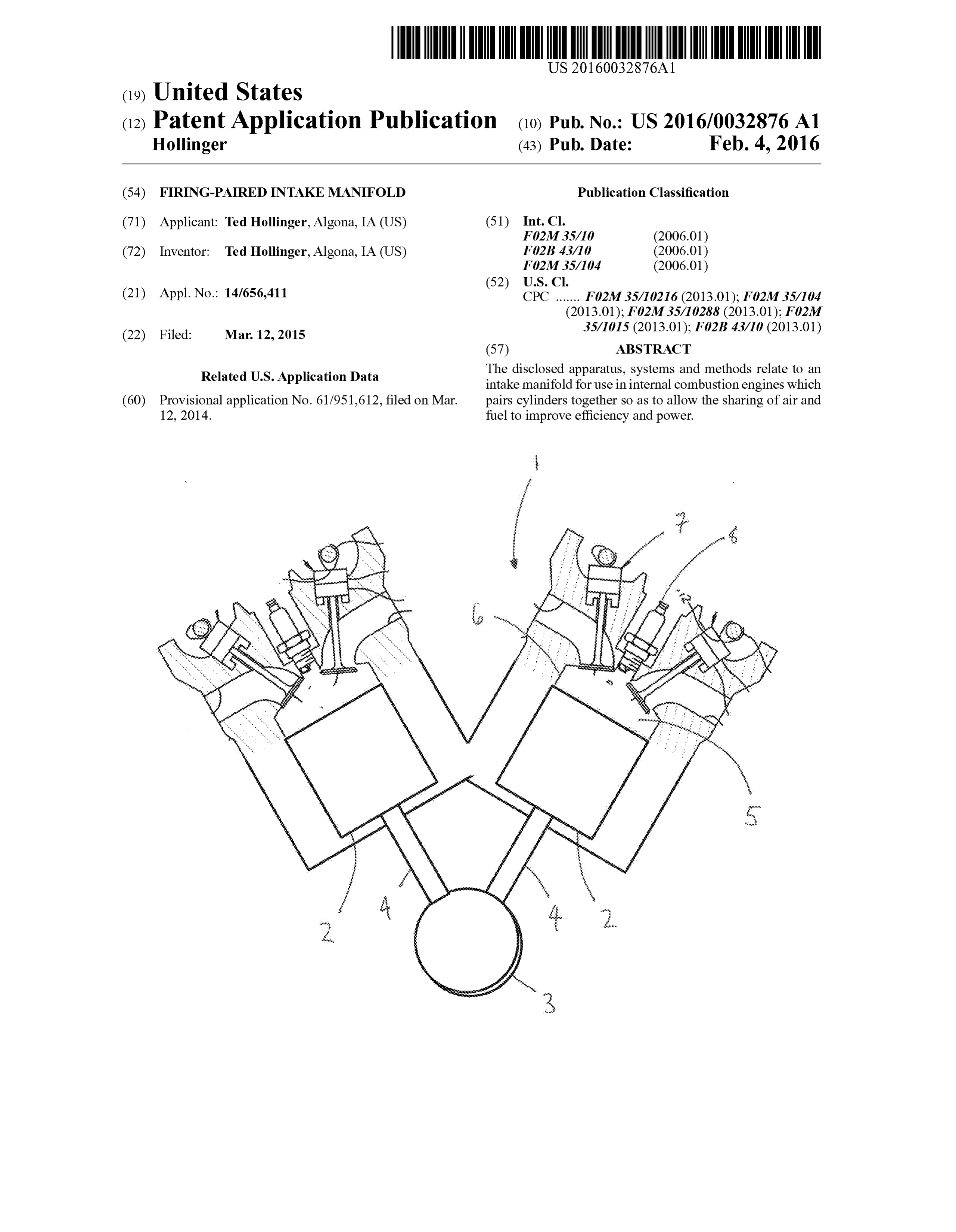
0003. The presently disclosed apparatus relates to an engine intake manifold, and more particularly to an intake BRIEF DESCRIPTION OF THE DRAWINGS manifold for hydrogen engines. 0017 FIG. 1 is a cross sectional schematic of a known 0004 Hydrogen is a renewable resource which presents V-style engine.
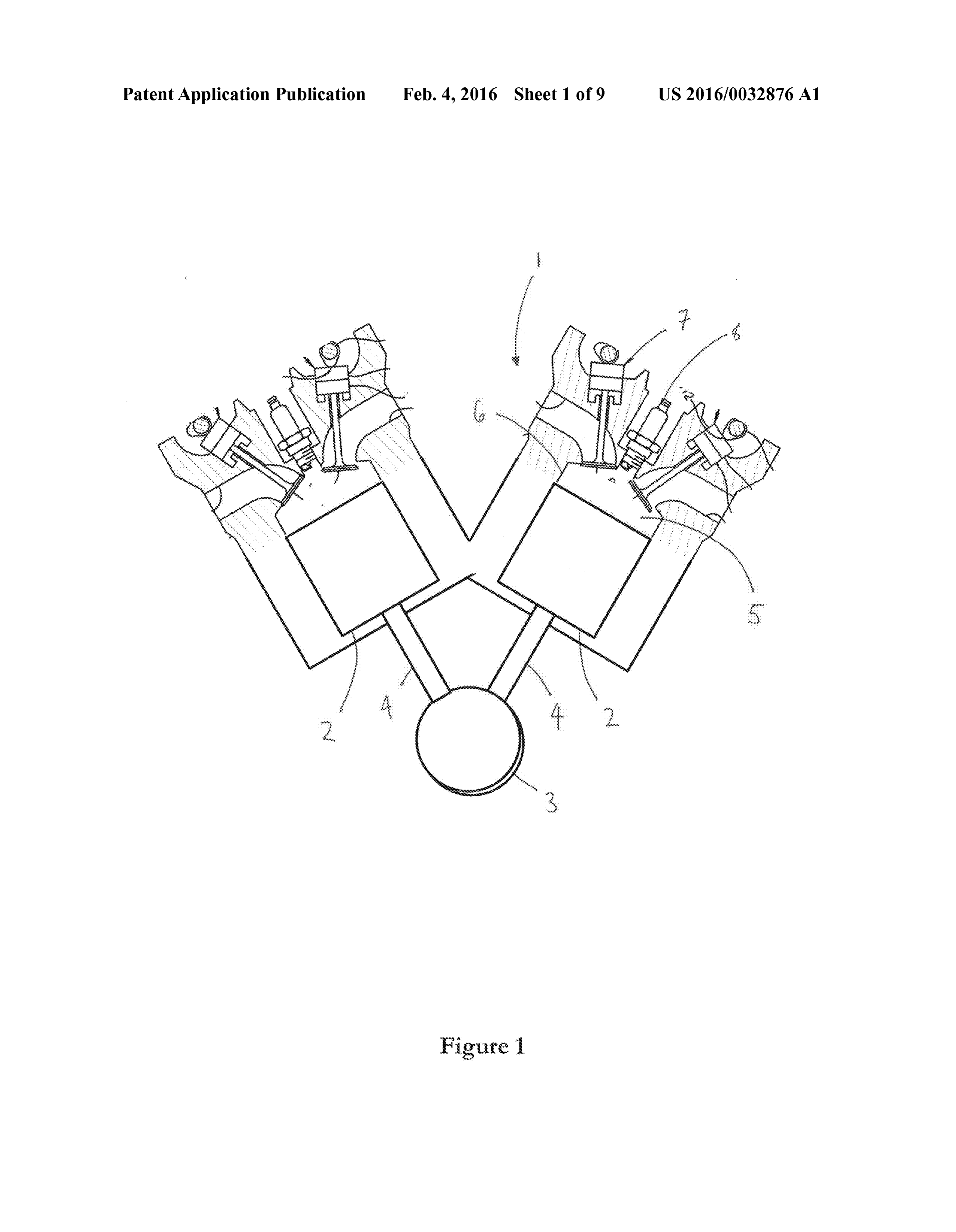
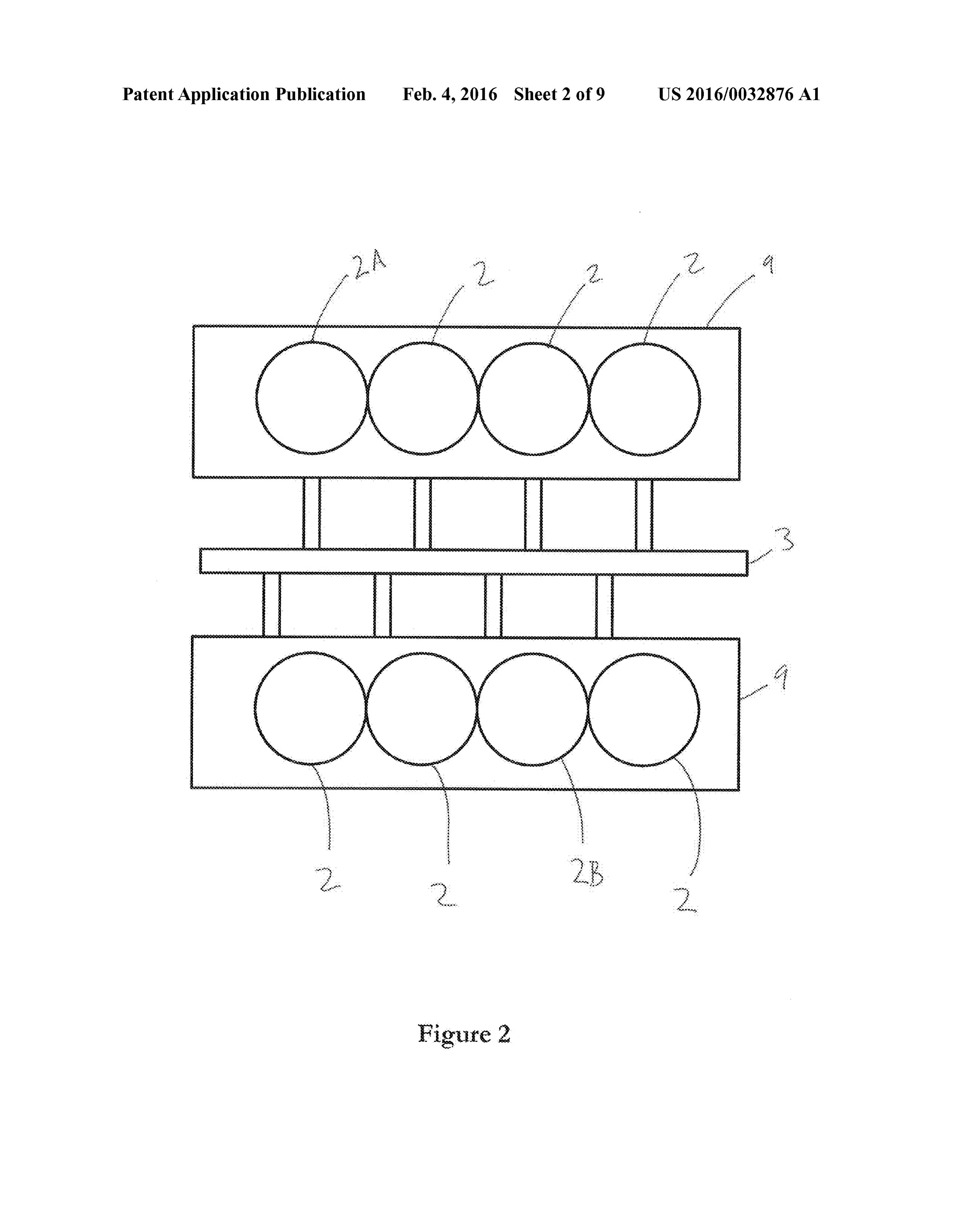
one possible alternative fuel for reduction of greenhouse gas 0018 FIG. 2 is a top-view representative schematic over emissions. One such application is in improving the effi view of a typical cylinder pattern for a known V8 engine. ciency of internal combustion engines while running a clean 0019 FIG. 3. depicts possible firing order patterns for a mixture of hydrogen and oxygen. Hydrogen powered engines Ford V8 engine.
have very few emissions and operate much cleaner than 0020 FIG. 4 is a front perspective view of an exemplary engines powered by diesel, gasoline. or even natural gas. embodiment of the intake manifold. Studies have indicated that emissions are heat, nitrogen, and 0021 FIG. 5 is a further perspective view of an alternate water and little else.
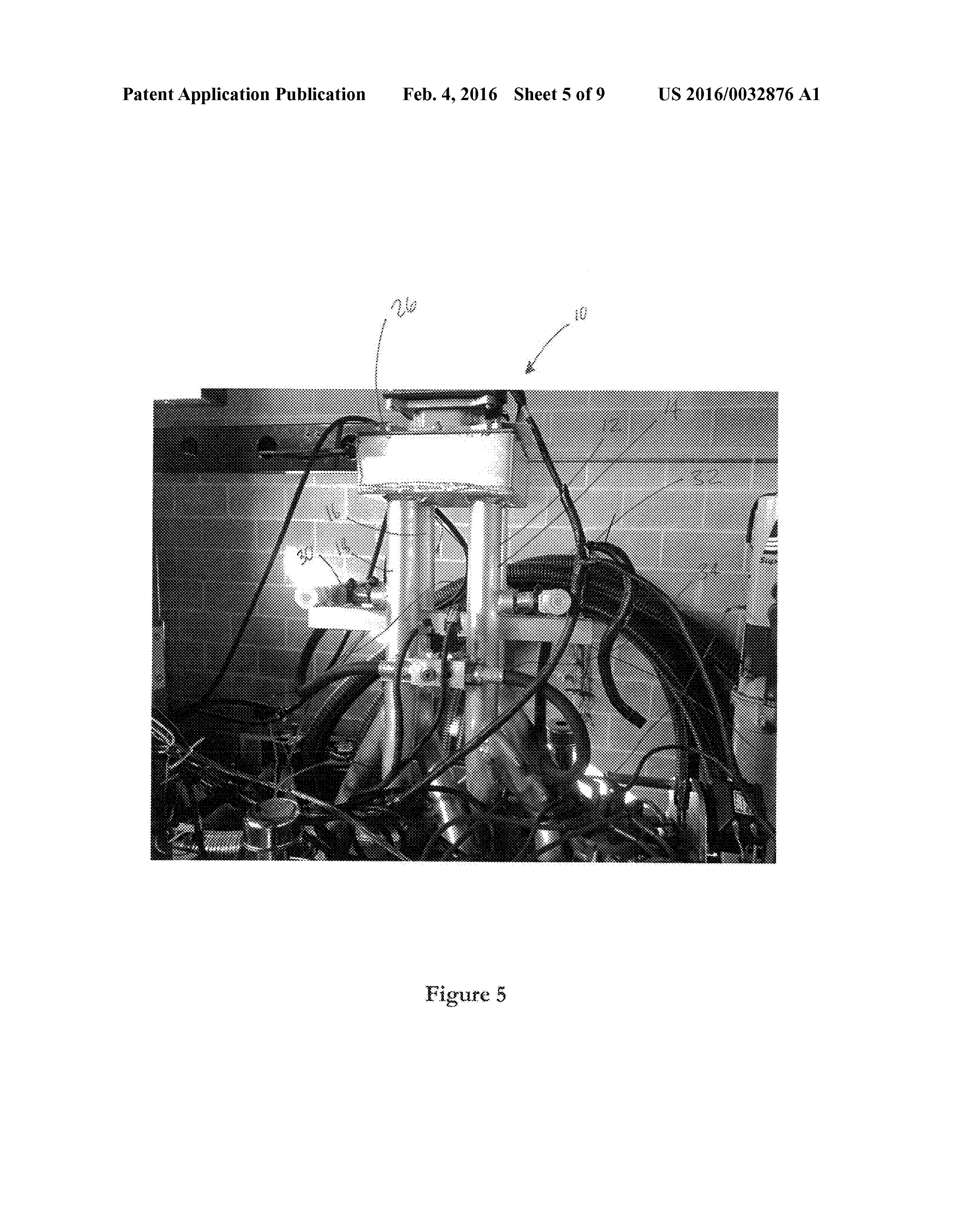
embodiment of the intake manifold.
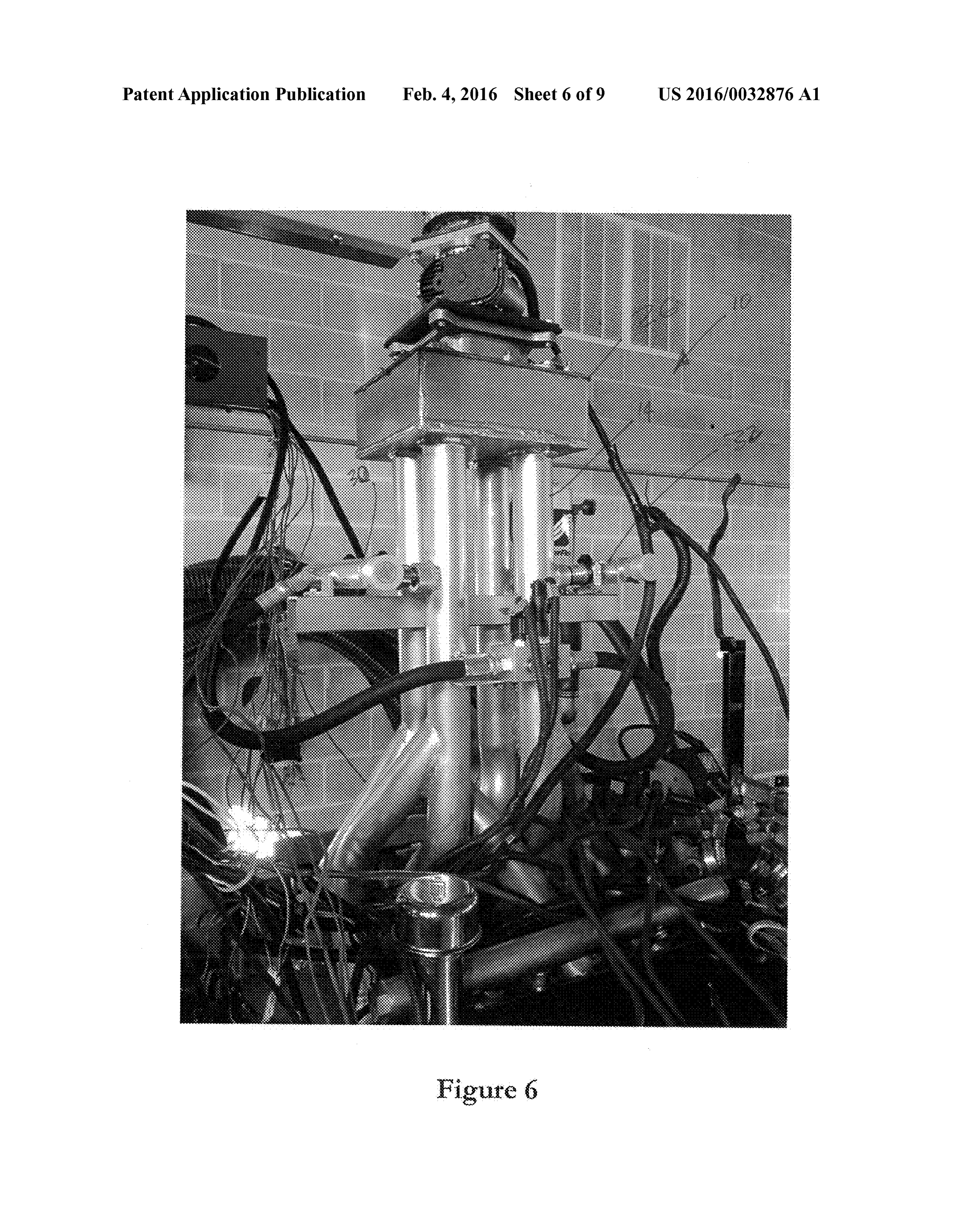
0005. The use of traditional cylinder engines as hydrogen powered engines present certain challenges, however. 0022 FIG. 6 is a further perspective view of the manifold embodiment of FIG. 5.
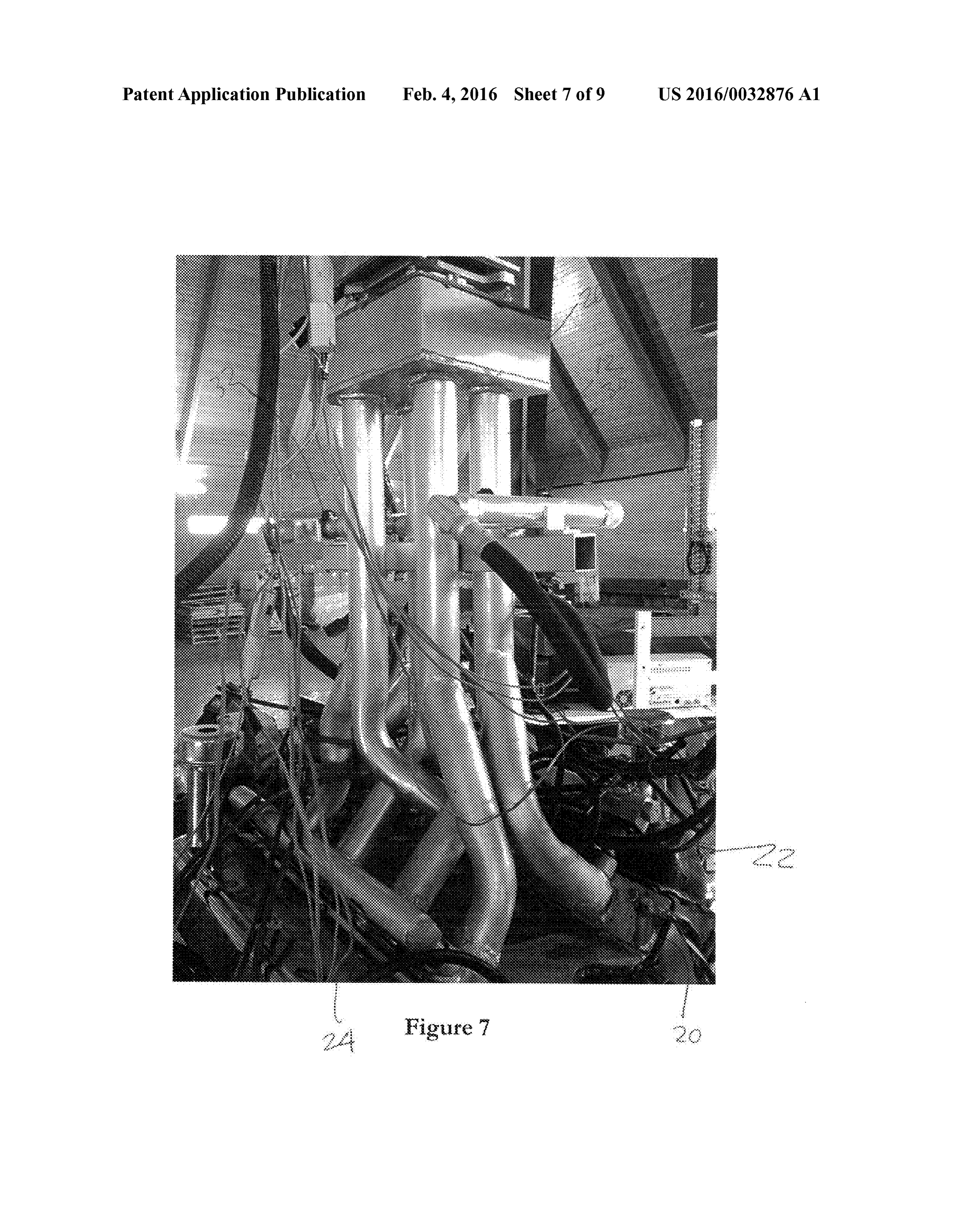
BRIEF SUMMARY (0023 FIG. 7 is a further perspective view of the manifold embodiment of FIG. 5.
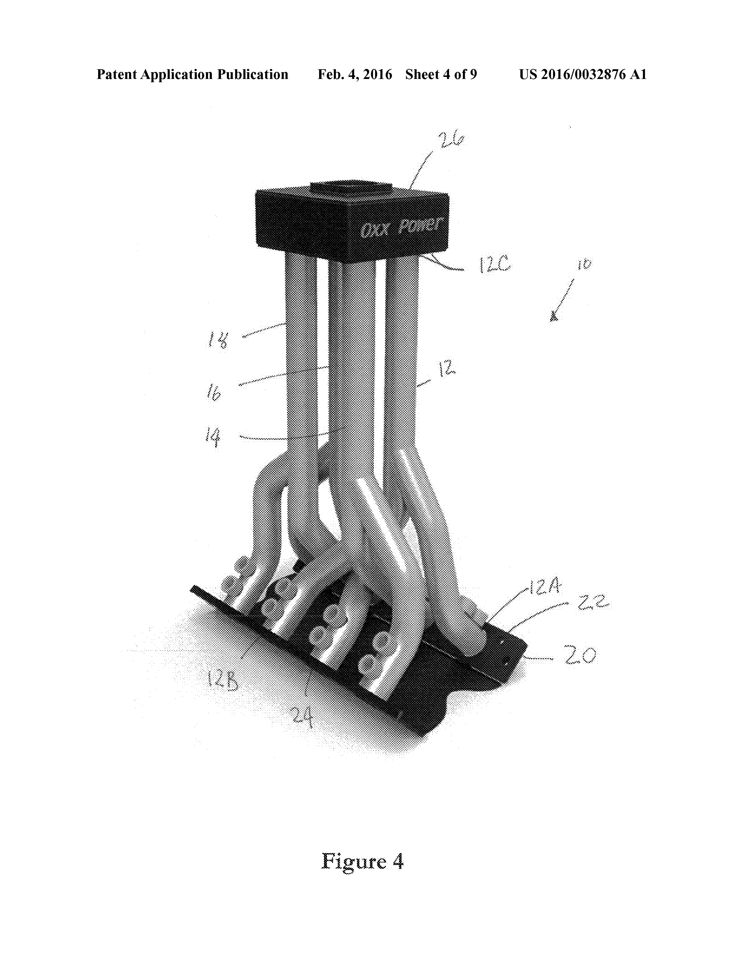
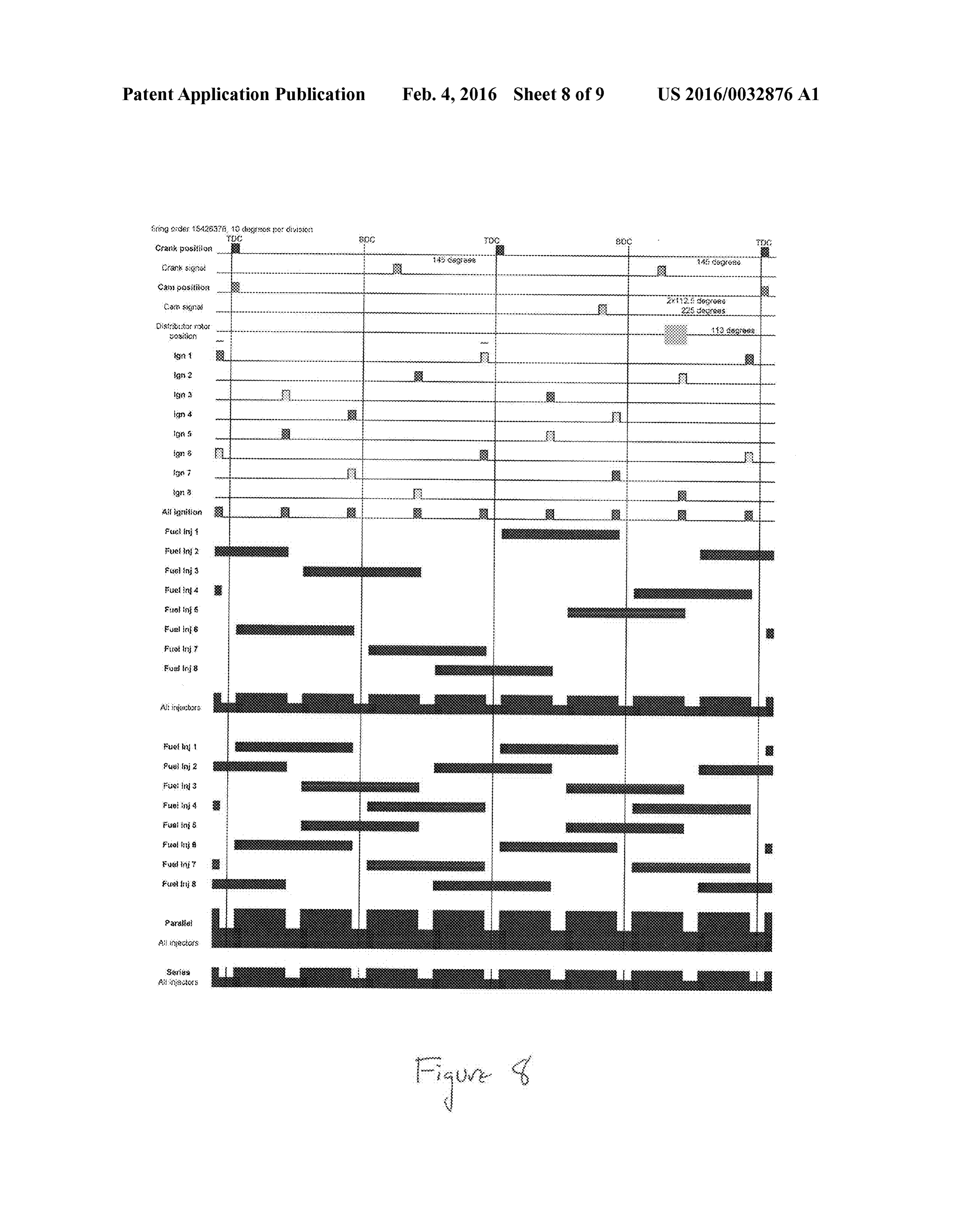
0006 Discussed herein are various embodiments relating 0024 FIG. 8 depicts a diagram showing a model firing, to a firing-paired intake manifold. cam, and injection schedule for a V8 engine with a 1-5-4-26 0007. In Example 1, an intake manifold comprises at least 3-7-8 firing order.
one elongate pipe, further comprising a bifurcated first end 0025 FIG. 9 depicts a diagram showing a model firing, adapted for providing fuel to two paired cylinders and a cam, and injection schedule for a V8 engine with a 1-5-4-2- second end.
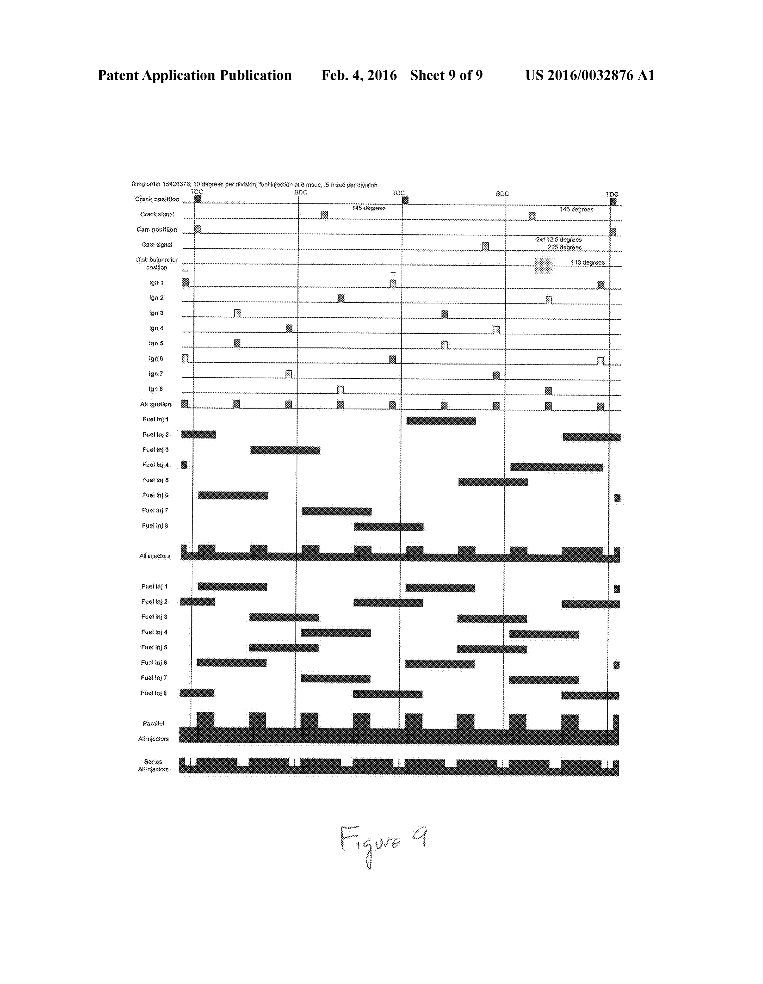
0008 Example 2 relates to the intake manifold according 6-3-7-8 firing order.
to Example 1, further comprising a plenum. DETAILED DESCRIPTION 0009 Example 3 relates to the intake manifold according to Example 2, further comprising at least one injector. 0026. The presently disclosed apparatus, systems and 00.10 Example 4 relates to the intake manifold according methods relate to various embodiments of an intake manifold to Example 3, wherein the intake manifold is configured for adapted for use with internal combustion engines. Forbrevity, use with a hydrogen engine. the various embodiments will be referred to collectively as a 0011 Example 5 relates to the intake manifold according “manifold' or “intake manifold’ though that is not intended to Example 4, wherein the intake manifold is configured for to limit the disclosure to any specific modality. use with a V8 engine. 0027. As is known in the art, an intake manifold is utilized 0012 Example 6 relates to an intake manifold system for by most fuel-powered engines to introduce the fuel/air mix use in power generation, comprising a four-stroke internal ture into the engine cylinders to distribute the fuel/air to each combustion engine comprising a plurality of combustion intake port and/or cylinder head. However, the traditional chambers fired in sequence, and an intake manifold in gas prior art manifolds present certain problems for internal com eous communication with the engine, the intake manifold bustion engines based on the physical configuration of the further comprising at least one pipe comprising a first bifur cylinders and the limited number of possible firing orders, cated end which comprises first and second combustion which inhibits the efficiency of the engine because various chamber attachment portions and a second end which extends cylinders are competing with one another for air. The pres substantially vertically above the chamber, wherein the first ently disclosed intake manifold addresses these limitations to and second combustion chamber attachment portions are in optimize the efficiency and performance of the engine. While sealed gaseous communication with one another and first and the discussion of this disclosure focuses on the use of hydro second paired combustion chambers. gen as a fuel, this manifold has applications in a variety of 0013 Example 7 relates to the intake manifold according other internal combustion engines, as would be apparent to to Example 6, wherein the plurality of combustion chambers one of skill in the art. Certain modifications inherent to the are fired at opposite points in the firing sequence. various fuels (gasoline, diesel, natural gas and the like) are
Page 12
US 2016/0032876 A1 Feb. 4, 2016
thereby contemplated. For example, the height of the mani the case of a typical V8 engine, individual pistons are paired fold pipes could be markedly lower in a gasoline powered such that the first cylinder 2A and second cylinder 2B are in engine, as it would not present the same buoyancy challenges. identical dead center positions on the crankshaft rotation but Further, the disclosed gaseous seals may also be fluid seals. are firing at opposing times. Meaning, while the first cylinder 0028 FIG. 1 depicts a typical known engine 1 has a num 2A is in the intake phase, the other cylinder 2B is in the ber of pistons 2, which are connect to the crankshaft3 by way exhaust phase, and vice versa. Accordingly, only one of these of rods 4. A combustion chamber 5 is formed at the between paired pistons has an open valve at any given time. the piston 2 and cylinderhead 6, where the fuel is let in by way 0033 Hydrogen has a very high flame velocity and is very of the valve 7, ignited by the sparkplug 8 to drive the piston easily ignited. The ignition of hydrogen and air can occur with down on the rod 4 and drive the crankshaft 3, thereby con very little energy and/or at relatively low temperatures. Verting the linear power of the moving pistons into radial Hydrogen's Lower Explosion Limit (LEL) is only 4%. power output. Critically for purposes of the manifold, in a Accordingly, it is imperative in a hydrogen-powered engine four-stroke engine the piston 2 goes through two 'up' and two that it be delivered to the combustion chamber after the "down” strokes per firing cycle. Such that intake happens exhaust valve is closed and shortly after the intake valve is exactly once. opened (as is described in detail in relation to FIGS. 1-2). 0029. As is shown in FIG. 2, and as is also well-known in Hydrogen engines are almost always sequentially port the art, the pistons 2 are arranged in the cylinder block 9. In injected. This means that the fuel injection system is synchro individual arrangements of two or more cylinders there is a nized to the camshaft position (as is depicted in reference to also a firing order, wherein the various pistons 2 are fired in a FIGS. 8-9) to optimize the efficiency of the engine. In appli specific sequence to drive the crankshaft 3. Different engines cations using various alternative fuels, adjustments can be manufactured by various companies have distinct firing made that would be apparent to one of skill in the art. The orders, and these are understood and well established in the critical issue is the pairing of the cylinders of a V6 or V8 art engine, for example, such that the fuel and air are drawn from 0030. As would be apparent to one of skill in the art, in a single pipe.
certain applications a variety offiring order combinations can 0034. The outcome of this combustion chamber pairing is be used, depending on the type of underlying engine, as that the valves for these cylinders will never be open at the discussed herein. For example, in certain embodiments the same time, thus combustion cannot happen on the wrong firing order can be set to 1-5-4-2-6-3-7-8 and each number in cylinder despite fueling two cylinders simultaneously. Fur the firing order is 90 degrees apart from the adjacent numbers, ther, the height of the pipes and the buoyancy of hydrogen therefore 1 & 6 are 360 degrees apart as are 5 & 3, 4 & 7 and result in excess hydrogen which may be left in the pipe rising 2 & 8. However, this presents a challenge wherein using a away from the hot exhaust, which prevents pre-ignition and prior art single-plane or two-plane intake manifold, as the 7th backfiring. Finally, the pairing of two cylinders with a single and 8th cylinders are set 90 degrees from one another and yet pipe results inabalancing of the firing of each cylinder, as any will attempt to draw air in sequence. excess hydrogen left in the manifold can be utilized by 0031. It is important to note that it is possible to nearly another cylinder in the firing order rapidly, before it is able to balance the crankshaft in certain configurations, but no con reach the plenum. This results in a more efficient and power figuration of the pistons in a V6 or V8 engine results in a ful engine.
situation in which two of the pistons are not competing for air with one another. Accordingly, there is no practical, func 0035 Turning to exemplary embodiments of the manifold tional crankshaft configuration Such that there are not cylin 10 in detail, and as depicted for in FIG. 4, certain embodi ders firing next to one another both in order and in proximity, ments make use of the engine's firing order pairing to provide which can cause those cylinders to be less efficient as they are the fuel and air to each combustion chamber in an improved competing with one another. As is depicted in FIG. 3, various manner, so as to address novel issues inherent in the use of this firing patterns which can be used in an engine to attempt to fuel. In certain embodiments, the manifold 10 comprises at balance and otherwise improve the function of the engine. least one hollow elongate shaft, or pipe 12, 14, 16, 18 extend Because of airflow considerations, certain orders are pre ing above the cylinder head 20. In exemplary embodiments, ferred. However, all circumstances result in a set of cylinders each pipe 12 has a first bifurcated end which divides into first in proximity which are firing next to one another and are 12A and second 12B combustion chamber attachment por competing for air with one another from a prior art manifold. tions, which accordingly are in gaseous communication with The presently disclosed intake manifold addresses the issue, two paired cylinders (as described above) at the respective Such that there is no competition for air, and also allows for cylinder heads 22, 24. Each pipe also has a second end 12C is increased efficiency because fuel which is not utilized by a in sealed gaseous communication with the plenum 26, which first paired cylinder can be quickly and easily utilized by the houses the throttle body. In certain embodiments, the fuel second paired cylinder. injectors are disposed at the first end, and the timing of the 0032. In certain exemplary embodiments, the intake mani injectors is controlled Such that the camshaft is controlled, as fold functions to pair cylinders which are in the same crank would be apparent to one of skill in the art. shaft position but opposite in the firing order in the same 0036. Accordingly, a single pipe 12 is able to provide fuel intake pipe so as to address some of the challenges present in to both paired cylinders simultaneously. However, because hydrogen engines. Rather than addressing the balance prob only one of the cylinders will be in the intake/firing phase at lem by way of the firing order, physical and crankshaft orga any given time, only that cylinder will draw fuel from the nization, the present manifold seeks to balance the engine by manifold 10 at that moment, while the other will not. In these delivering air to pairs of the cylinders at differing locations by configurations, a first cylinder is thereby in the intake phase pairing the cylinders. The critical aspect for purposes of the while the paired cylinder is in the power phase, thus both are manifold is that in certain of these configurations, such as in moving in concert.
Page 13
US 2016/0032876 A1 Feb. 4, 2016
0037. Further, the minimum height of the tube is based number of injectors that are necessary and insures that cylin upon on how high hydrogen will rise between valves opening ders are not competing for air. Each cylinder receives the and closing in each pipe depending on the speed desired and same amount of air and makes it possible for each cylinder to the known buoyancy of hydrogen. For example, in an engine achieve equal amounts of power, applying equal amounts of designed to run steadily at higher RPM, a lower pipe length is torque to the crankshaft, allowing the engine to run more required. Smoothly generating more power. In exemplary embodi 0038. As is shown in FIG. 5, in certain exemplary embodi ments, a cam sensor is not needed, as only one value is open ments of the manifold 10 further comprises a second set of at one time and hydrogen is injected in both sides simulta fuel rails 30, 32, 34, 36 in communication with each pipe 12, neously.
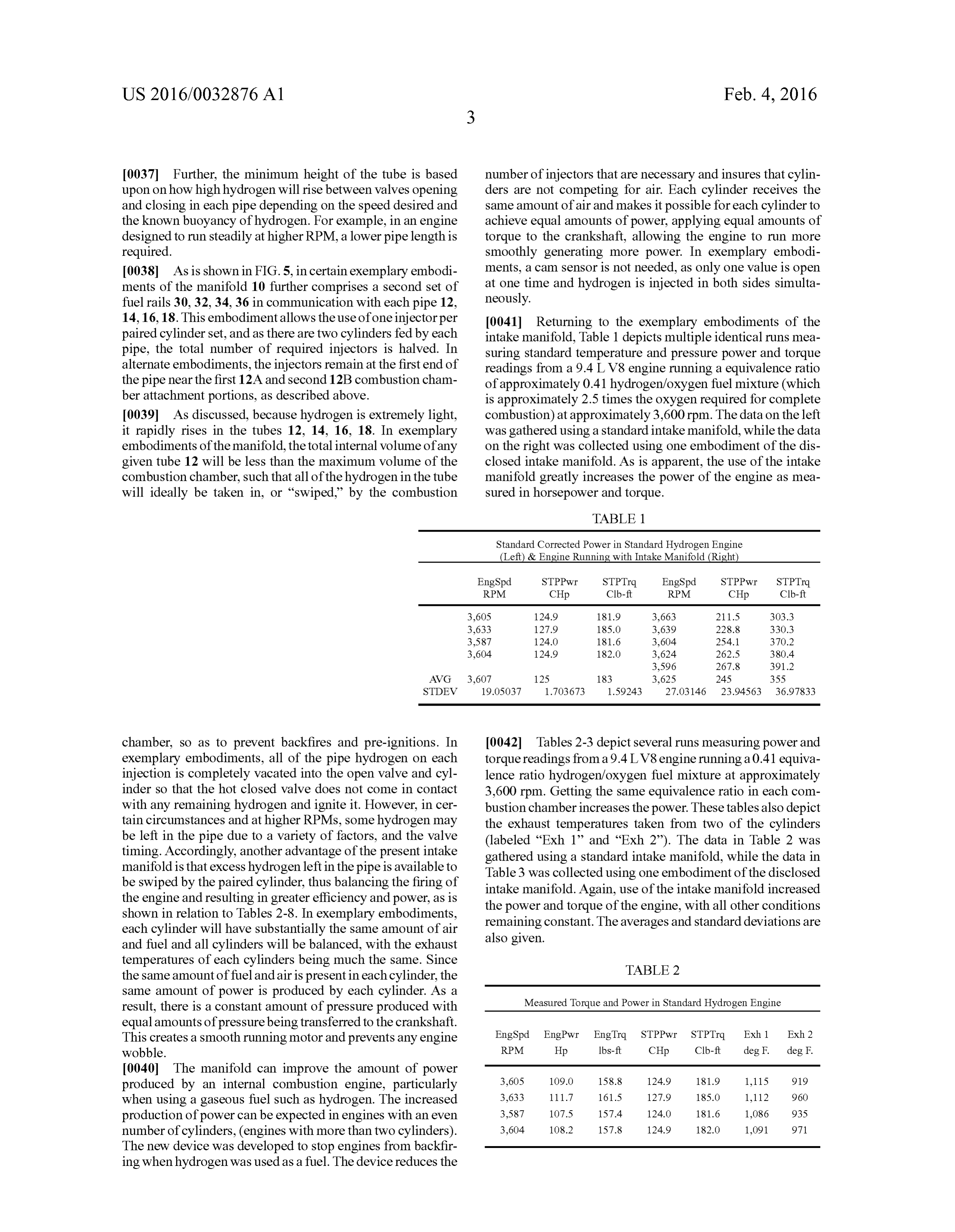
14, 16, 18. This embodimentallows the use of one injectorper 0041 Returning to the exemplary embodiments of the paired cylinder set, and as there are two cylinders fed by each intake manifold, Table 1 depicts multiple identical runs mea pipe, the total number of required injectors is halved. In Suring standard temperature and pressure power and torque alternate embodiments, the injectors remain at the first end of readings from a 9.4L V8 engine running a equivalence ratio the pipe near the first 12A and second 12B combustion cham of approximately 0.41 hydrogen/oxygen fuel mixture (which ber attachment portions, as described above. is approximately 2.5 times the oxygen required for complete 0039. As discussed, because hydrogen is extremely light, combustion) at approximately 3,600 rpm. The data on the left it rapidly rises in the tubes 12, 14, 16, 18. In exemplary was gathered using a standard intake manifold, while the data embodiments of the manifold, the total internal volume of any on the right was collected using one embodiment of the dis given tube 12 will be less than the maximum volume of the closed intake manifold. As is apparent, the use of the intake combustion chamber, such that all of the hydrogen in the tube manifold greatly increases the power of the engine as mea will ideally be taken in, or “swiped by the combustion Sured in horsepower and torque.
TABLE 1.
Standard Corrected Power in Standard Hydrogen Engine
Left) & Engine Running with Intake Manifold (Right
EngSpd STPPwr STPTrq EngSpd STPPwr STPTrq
RPM CHp Clb-ft RPM CHp Clb-ft
AVG 3,607 125 183 3,625 245 355
STDEV 19.OSO37 1.703673 15924.3 27.03146 23.94563 36.978.33
chamber, so as to prevent backfires and pre-ignitions. In 0042 Tables 2-3 depict several runs measuring power and exemplary embodiments, all of the pipe hydrogen on each torque readings from a 9.4L V8 engine running a 0.41 equiva injection is completely vacated into the open valve and cyl lence ratio hydrogen/oxygen fuel mixture at approximately inder so that the hot closed valve does not come in contact 3,600 rpm. Getting the same equivalence ratio in each com with any remaining hydrogen and ignite it. However, in cer bustion chamber increases the power. These tables also depict tain circumstances and at higher RPMs, some hydrogen may the exhaust temperatures taken from two of the cylinders be left in the pipe due to a variety of factors, and the valve (labeled “Exh 1” and “Exh 2'). The data in Table 2 was timing. Accordingly, another advantage of the present intake gathered using a standard intake manifold, while the data in manifold is that excess hydrogen left in the pipe is available to Table 3 was collected using one embodiment of the disclosed be swiped by the paired cylinder, thus balancing the firing of intake manifold. Again, use of the intake manifold increased the engine and resulting in greater efficiency and power, as is the power and torque of the engine, with all other conditions shown in relation to Tables 2-8. In exemplary embodiments, remaining constant. The averages and Standard deviations are each cylinder will have substantially the same amount of air also given.
and fuel and all cylinders will be balanced, with the exhaust temperatures of each cylinders being much the same. Since TABLE 2 the same amount of fuel and air is present in each cylinder, the same amount of power is produced by each cylinder. As a result, there is a constant amount of pressure produced with Measured Torque and Power in Standard Hydrogen Engine equal amounts of pressure being transferred to the crankshaft.
This creates a Smooth running motor and prevents any engine EngSpd EngPwr EngTrq STPPwr STPTrq Exh 1 Exh 2 wobble. RPM Hp Ibs-ft CHp Clb-ft deg F. deg F. 0040. The manifold can improve the amount of power produced by an internal combustion engine, particularly 3,605 109.0 158.8 1249 1819 1,115 919 when using a gaseous fuel Such as hydrogen. The increased 3,633 111.7 161.5 127.9 185.0 1,112 960 production of power can be expected in engines with an even 3,587 107.5 157.4 124.0 1816 1,086 935 number of cylinders, (engines with more than two cylinders). 3,604 108.2 157.8 1249 182.0 1,091 971 The new device was developed to stop engines from backfir ing when hydrogen was used as a fuel. The device reduces the
Page 14
US 2016/0032876 A1 Feb. 4, 2016
TABLE 3 TABLE 7-continued
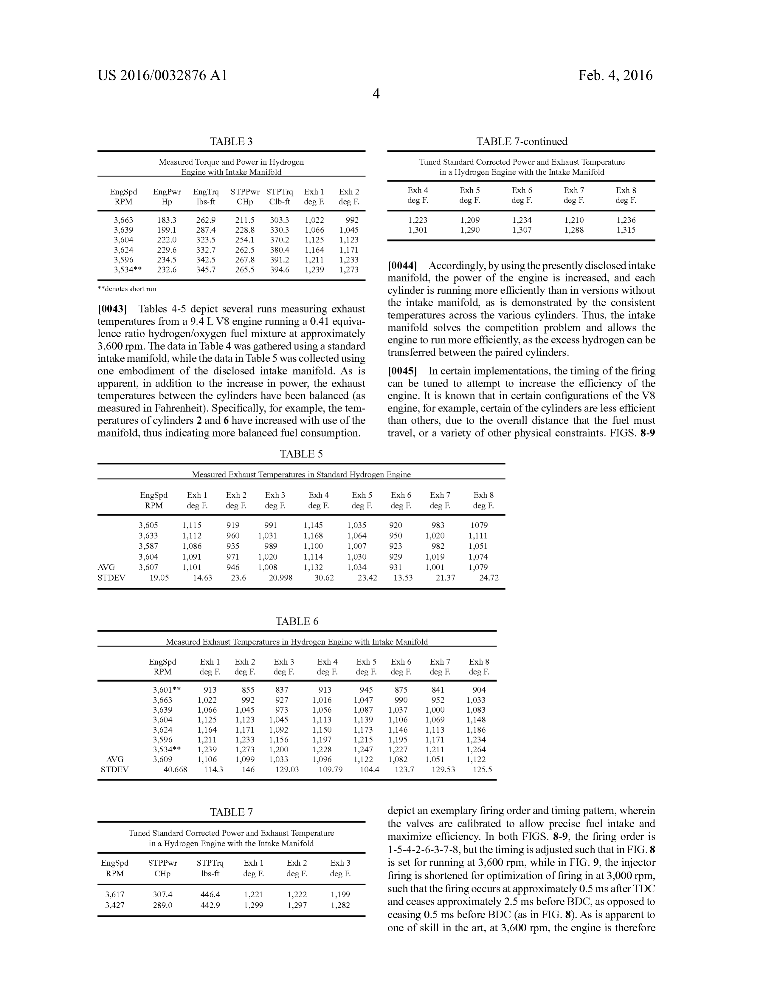
Measured Torque and Power in Hydrogen Tuned Standard Corrected Power and Exhaust Temperature Engine with Intake Manifold in a Hydrogen Engine with the Intake Manifold EngSpd EngPwr EngTra. STPPwr STPTrq Exh 1 Exh 2 Exh 4 Exh S Exh 6 Exh. 7 Exh 8 RPM Hp Ibs-ft CHp Clb-ft deg F. deg F. deg F. deg F. deg F. deg F. deg F. 3,663 183.3 262.9 211.S. 303.3 1,022 992 1,223 1,209 1,234 1,210 1,236
3,534** 232.6 345.7 26S.S. 394.6 1,239 1273 0044 Accordingly, by using the presently disclosed intake manifold, the power of the engine is increased, and each denotes short run cylinder is running more efficiently than in versions without 0043 Tables 4-5 depict several runs measuring exhaust the intake manifold, as is demonstrated by the consistent temperatures from a 9.4L V8 engine running a 0.41 equiva temperatures across the various cylinders. Thus, the intake lence ratio hydrogen/oxygen fuel mixture at approximately manifold solves the competition problem and allows the 3,600 rpm. The data in Table 4 was gathered using a standard engine to run more efficiently, as the excess hydrogen can be intake manifold, while the data in Table 5 was collected using transferred between the paired cylinders. one embodiment of the disclosed intake manifold. As is 0045. In certain implementations, the timing of the firing apparent, in addition to the increase in power, the exhaust can be tuned to attempt to increase the efficiency of the temperatures between the cylinders have been balanced (as engine. It is known that in certain configurations of the V8 measured in Fahrenheit). Specifically, for example, the tem engine, for example, certain of the cylinders are less efficient peratures of cylinders 2 and 6 have increased with use of the than others, due to the overall distance that the fuel must manifold, thus indicating more balanced fuel consumption. travel, or a variety of other physical constraints. FIGS. 8-9
TABLE 5
Measured Exhaust Temperatures in Standard Hydrogen Engine
EngSpd Exh 1 Exh 2 Exh 3 Exh 4 Exh5 Exh 6 Exh. 7 Exh 8
RPM deg F. deg F. deg F. deg F. deg F. deg F. deg F. deg F.
AVG 3,607 1,101 946 1,008 1,132 1,034 931 1,001 1,079 STDEV 19. OS 14.63 23.6 20.998 30.62 23.42 13.53 21.37 24.72
TABLE 6
Measured Exhaust Temperatures in Hydrogen Engine with Intake Manifold
EngSpd Exh 1 Exh 2 Exh 3 Exh 4 Exh 5 Exh 6 Exh. 7 Exh 8
RPM deg F. deg F. deg F. deg F. deg F. deg F. deg F. deg F.
3,601* * 913 855 837 913 945 875 841 904
3,534** 1,239 1273 1,200 1,228 1,247 1,227 1,211 1,264
AVG 3,609 1,106 1,099 1,033 1,096 1,122 1,082 1,051 1,122 STDEV 40.668. 114.3 146 129.03 109.79 104.4 123.7 129.53 125.5
TABLE 7 depict an exemplary firing order and timing pattern, wherein the valves are calibrated to allow precise fuel intake and
Tuned St.
Ill 8 cert re ES statue
OSC 96 W. e e 8O maximize efficiency. In both FIGS. 8-9, the firing order is ydrog 9. 1-5-4-2-6-3-7-8, but the timing is adjusted such that in FIG.8 EngSpd STPPwr STPTrq Exh 1 Exh 2 Exh 3 is set for running at 3,600 rpm, while in FIG. 9, the injector RPM CHp Ibs-ft deg F. deg F. deg F. firing is shortened for optimization of firing in at 3,000 rpm, 3,617 307.4 446.4 1,221 1,222 1,199 such that the firing occurs at approximately 0.5 ms after TDC 3.427 289.0 442.9 1299 1297 1282 and ceases approximately 2.5 ms before BDC, as opposed to ceasing 0.5 ms before BDC (as in FIG. 8). As is apparent to one of skill in the art, at 3,600 rpm, the engine is therefore
Page 15
US 2016/0032876 A1 Feb. 4, 2016
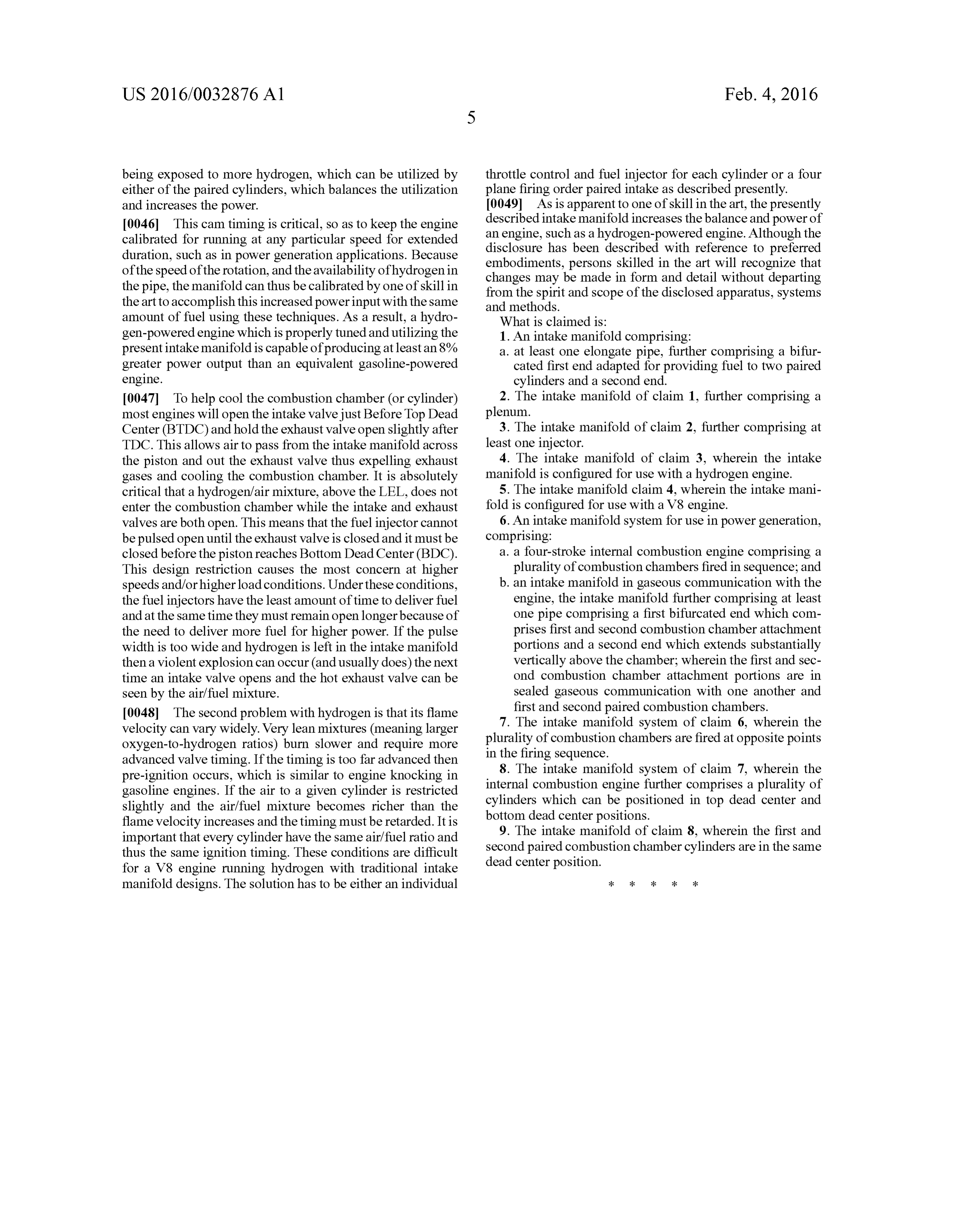
being exposed to more hydrogen, which can be utilized by throttle control and fuel injector for each cylinder or a four either of the paired cylinders, which balances the utilization plane firing order paired intake as described presently. and increases the power. 0049. As is apparent to one of skill in the art, the presently 0046. This cam timing is critical, so as to keep the engine described intake manifold increases the balance and power of calibrated for running at any particular speed for extended an engine, Such as a hydrogen-powered engine. Although the duration, such as in power generation applications. Because disclosure has been described with reference to preferred of the speed of the rotation, and the availability of hydrogen in embodiments, persons skilled in the art will recognize that the pipe, the manifold can thus be calibrated by one of skill in changes may be made in form and detail without departing from the spirit and scope of the disclosed apparatus, Systems the art to accomplish this increased power input with the same and methods.
amount of fuel using these techniques. As a result, a hydro What is claimed is:
gen-powered engine which is properly tuned and utilizing the 1. An intake manifold comprising: present intake manifold is capable of producing at least an 8% a. at least one elongate pipe, further comprising a bifur greater power output than an equivalent gasoline-powered cated first end adapted for providing fuel to two paired engine. cylinders and a second end. 0047. To help cool the combustion chamber (or cylinder) 2. The intake manifold of claim 1, further comprising a most engines will open the intake valve just Before Top Dead plenum.
Center (BTDC) and hold the exhaust valve open slightly after 3. The intake manifold of claim 2, further comprising at TDC. This allows air to pass from the intake manifold across least one injector.
the piston and out the exhaust valve thus expelling exhaust 4. The intake manifold of claim 3, wherein the intake gases and cooling the combustion chamber. It is absolutely manifold is configured for use with a hydrogen engine. critical that a hydrogen/air mixture, above the LEL, does not 5. The intake manifold claim 4, wherein the intake mani enter the combustion chamber while the intake and exhaust fold is configured for use with a V8 engine. valves are both open. This means that the fuel injector cannot 6. An intake manifold system for use in power generation, be pulsed open until the exhaust valve is closed and it must be comprising:
closed before the piston reaches Bottom Dead Center (BDC). a. a four-stroke internal combustion engine comprising a This design restriction causes the most concern at higher plurality of combustion chambers fired in sequence; and speeds and/or higher load conditions. Under these conditions, b. an intake manifold in gaseous communication with the the fuel injectors have the least amount of time to deliver fuel engine, the intake manifold further comprising at least and at the same time they must remain open longer because of one pipe comprising a first bifurcated end which com the need to deliver more fuel for higher power. If the pulse prises first and second combustion chamber attachment width is too wide and hydrogen is left in the intake manifold portions and a second end which extends Substantially then a violent explosion can occur (and usually does) the next vertically above the chamber; wherein the first and sec time an intake valve opens and the hot exhaust valve can be ond combustion chamber attachment portions are in seen by the air/fuel mixture. sealed gaseous communication with one another and 0048. The second problem with hydrogen is that its flame first and second paired combustion chambers. Velocity can vary widely. Very lean mixtures (meaning larger 7. The intake manifold system of claim 6, wherein the oxygen-to-hydrogen ratios) burn slower and require more plurality of combustion chambers are fired at opposite points advanced valve timing. If the timing is too far advanced then in the firing sequence.
pre-ignition occurs, which is similar to engine knocking in 8. The intake manifold system of claim 7, wherein the gasoline engines. If the air to a given cylinder is restricted internal combustion engine further comprises a plurality of slightly and the air/fuel mixture becomes richer than the cylinders which can be positioned in top dead center and flame velocity increases and the timing must be retarded. It is bottom dead center positions.
important that every cylinder have the same air/fuel ratio and 9. The intake manifold of claim 8, wherein the first and thus the same ignition timing. These conditions are difficult second paired combustion chamber cylinders are in the same for a V8 engine running hydrogen with traditional intake dead center position.
manifold designs. The solution has to be either an individual
Provenance
- Collection
- Patents citing this work
- Pages
- 15
- Method
- pdftotext (the PDF's own text layer) + pdftoppm 300dpi page scans
- Patent office record
- patents.google.com →
- Source
- Google Patents citing-documents table
- Assignee
- Ted Hollinger
- Inventors
- Ted Hollinger
- Published
- 2016-02-04
- Transcribed from
- patentimages.storage.googleapis.com →