patent · US6209502
Intake manifold with multiple stage ram induction
3 April 2001
Page 1 — bibliographic record
(12) United States Patent (10) Patent No.: US 6,209,502 B1 Davis et al. (45) Date of Patent: Apr. 3, 2001
(54) INTAKE MANIFOLD WITH MULTIPLE 431221 * 7/1935 (GB) ............................... 123/184.39 STAGE RAM INDUCTION 52-77907 12/1975 (JP).
52-32416 * 3/1977 (JP) ................................. 123/184.46 (76) Inventors: Gregory G. Davis, 4059 Hillside Ave.,
Norco, CA (US) 92680; Kenneth * cited by examiner
Thurm, 2348 N. Rockridge Cir.,
Primary Examiner Noah P. Kamen (*) Notice: Subject to any disclaimer, the term of this (74) Attorney, Agent, or Firm-Kit M. Stetina; Thomas C. p a -- is Sh adjusted under 35 y U dayS.
Naber; Stetina Brunda Garred & Brucker
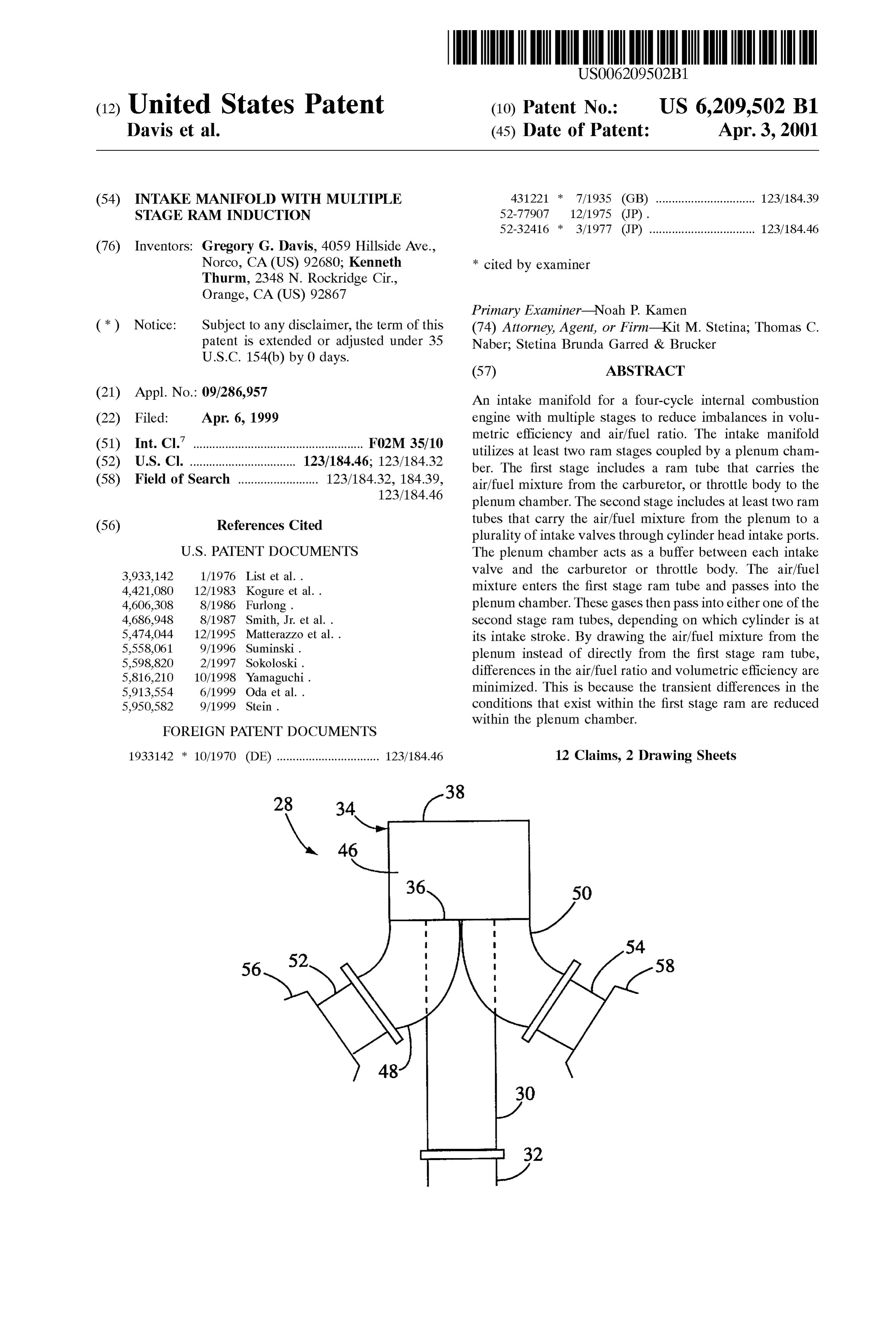
(21) Appl. No.: 09/286,957 An intake manifold for a four-cycle internal combustion (22) Filed: Apr. 6, 1999 engine with multiple Stages to reduce imbalances in Volu 7 metric efficiency and air/fuel ratio. The intake manifold (51) Int. Cl.' ..................................................... Fo2M 35/10 utilizes at least two ram Stages coupled by a plenum cham (52) U.S. Cl. ................................. 123/184.46; 123/184.32 ber. The first stage includes a ram tube that carries the (58) Field of Search ......................... 123/184.32, 184.39, air/fuel mixture from the carburetor, or throttle body to the 123/184.46 plenum chamber. The Second Stage includes at least two ram (56) References Cited tubes that carry the air/fuel mixture from the plenum to a plurality of intake valves through cylinder head intake ports.
3.933.142 1/1976 List et all valve and the carburetor or throttle body. The air/fuel 4.421,080 12/1983 Kogure et al.. mixture enters the first stage ram tube and passes into the 4,606,308 8/1986 Furlong. plenum chamber. These gases then pass into either one of the 4,686,948 8/1987 Smith, Jr. et al.. Second Stage ram tubes, depending on which cylinder is at
et al. . its intake stroke. By drawing the air/fuel mixture from the 2- - -2 o plenum instead of directly from the first stage ram tube, 5. 6.E. R differences in the air/fuel ratio and Volumetric efficiency are so13,554 6/1999 Oda g minimized. This is because the transient differences in the 5950,582 9/1999 Stein. conditions that exist within the first Stage ram are reduced FOREIGN PATENT DOCUMENTS within the plenum chamber.
1933142 * 10/1970 (DE) ................................ 123/184.46 12 Claims, 2 Drawing Sheets
Page 2
Drawing sheet — no readable text.
Page 3
Drawing sheet — no readable text.
Page 4
INTAKE MANIFOLD WITH MULTIPLE mixture enters the first stage ram tube and passes into the STAGE RAM INDUCTION plenum chamber. These gases then pass into either one of the Second Stage ram tubes, depending on which cylinder is at
FIELD OF THE INVENTION its intake stroke. By drawing the air/fuel mixture from the The present invention relates to the field of four-cycle plenum instead of directly from the first Stage ram tube, internal combustion engines, and more particularly to a differences in the air/fuel ratio and Volumetric efficiency are multiple stage ram intake manifold for a four-cycle internal minimized. This is because the transient differences in the combustion engine. conditions that exist within the first Stage ram are reduced within the plenum chamber. For example, differences in the
BACKGROUND OF THE INVENTION air/fuel mixture that depend on the time interval between Internal combustion engines generate power by igniting a Successive power impulses, resulting from "odd fire' power mixture of fuel and air. In order to get the most power from pulses, are lessened within the plenum chamber. The result the fuel, that is, for the most efficient operation, many is that the conditions within the plenum chamber are much parameters of the combustion proceSS must be optimized. 15 more stable than within the first stage ram tube so that both Much research has gone into finding ways to increase cylinderS receive charges that are more Similar and the efficiency by varying these parameters. As a result, the fuel engine runs in a more balanced manner. efficiency, and hence fuel economy of vehicles, has BRIEF DESCRIPTION OF THE FIGURES improved dramatically.
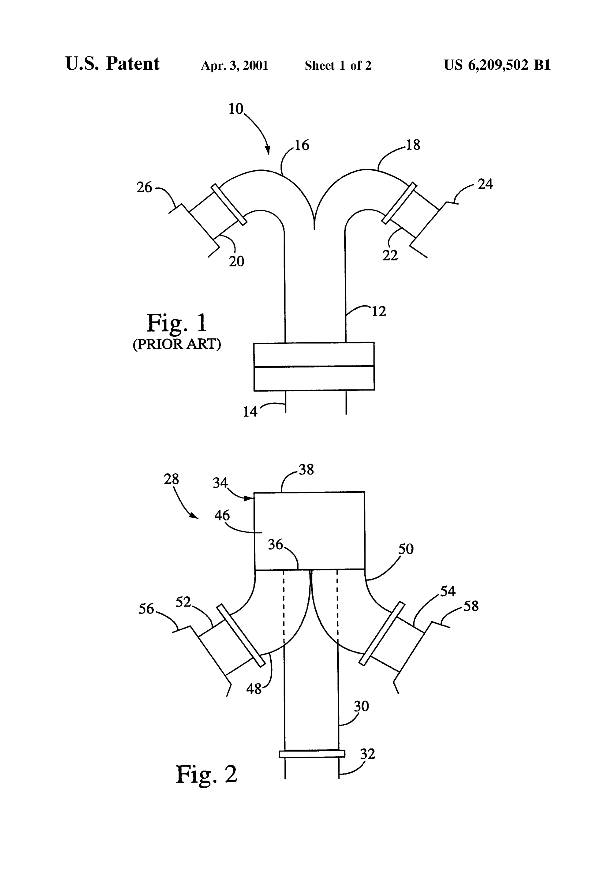
Two of the important factors affecting the efficiency of FIG. 1 shows a diagram of an intake manifold in accor internal combustion engines are air/fuel ratio and Volumetric dance with the prior art.
efficiency. Volumetric efficiency is defined as the volume FIG. 2 shows a top view of an intake manifold for a flow rate of air into the intake system divided by the rate at two-cylinder engine in accordance with a preferred embodi which volume is displaced by the piston. Not only is it ment of the present invention.
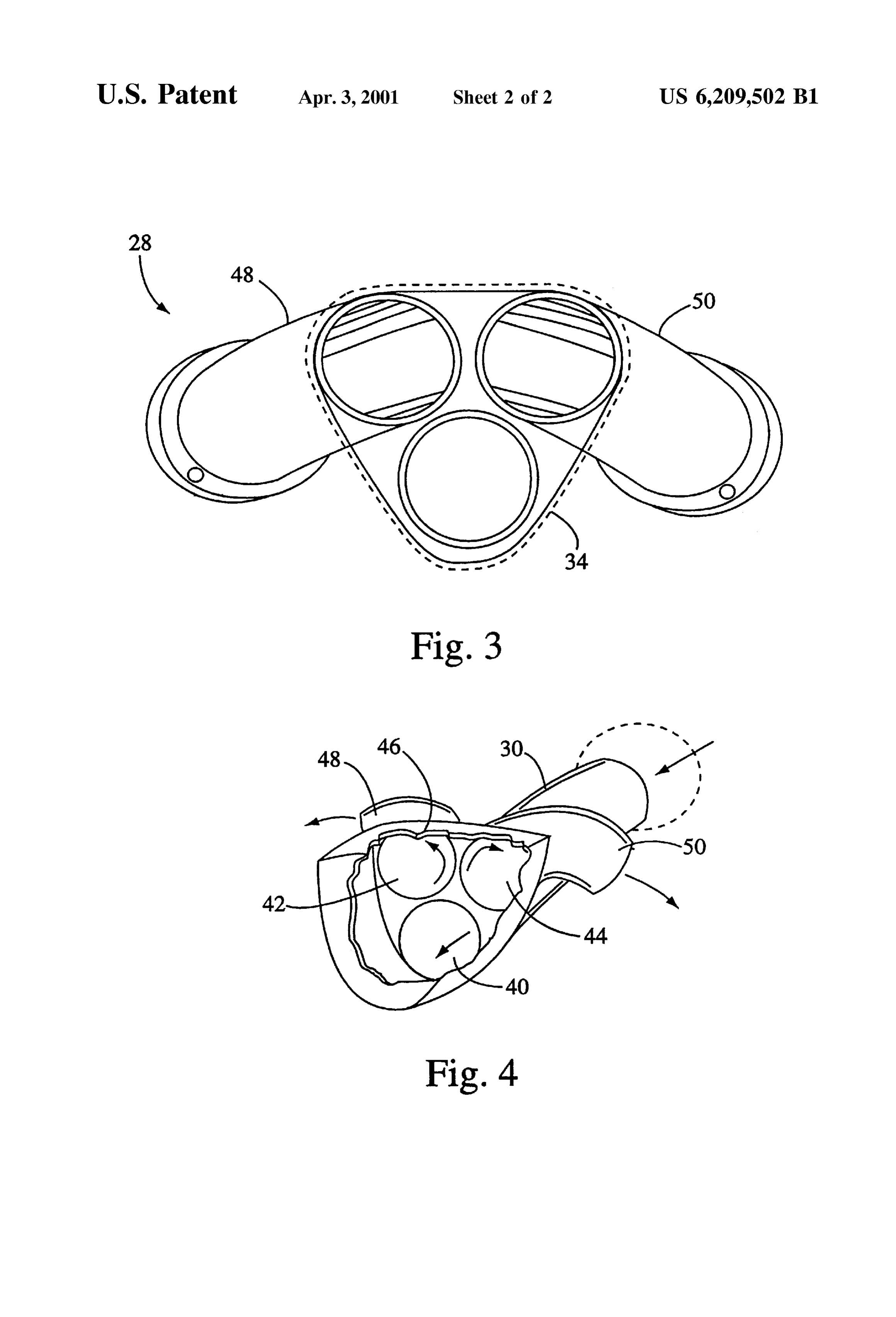
important for these parameters to be optimized for each 25 FIG. 3 is a cross-sectional view of the intake manifold cylinder but it is also important to minimize variations in shown in FIG. 2.
these parameters. Such variations can occur within a given FIG. 4 is a cut-away perspective view of the intake cylinder at different times, or can occur between individual manifold shown in FIG. 3.
cylinders in an engine. Undesirable variations in combustion parameters will create imbalances in the engine's operation DETAILED DESCRIPTION OF THE DRAWINGS that will affect efficiency and overall performance.
One example of such an imbalance is known as "odd fire” The present invention is an intake manifold for an internal power impulses. This occurs, for example, in two cylinder, combustion engine. In a preferred embodiment of the inven 45-degree V-Twin motorcycle engines. In these engines tion the inventive concepts will be applied to a two cylinder, there occurs an interval of 315 degrees of crankshaft rotation 35 four-cycle, 45 degree V-Twin motorcycle engine. While this between a first pair of power impulses, followed by an embodiment is used herein to illustrate the invention, it will interval of 405 degrees between the following two power be appreciated that many other configurations and types of impulses. The different spacing results in different air/fuel internal combustion engines may also benefit by incorpo conditions occurring in the intake manifold when the charge rating the teachings of the invention. For example, the enters the cylinder. Such differences may result from varia 40 invention may be applied to engines other than motorcycle tions in factorS Such as temperature, preSSure or turbulence engines and to engines having different numbers of cylin inside the intake manifold. ders. Also, the intake manifold may be configured to Supply In any event, these variations cause the cylinders to fire a different number of cylinders. By using the teachings of with different air/fuel ratios and different volumetric effi the present invention, adapting the intake manifold of the ciencies depending on whether they fire after the 315-degree 45 preferred embodiment to other types of engines will be interval or the 405-degree interval. This affects the way the within the ordinary abilities of one skilled in the art. engine operates, for example it results in timing differences Referring to FIG. 1, there is shown a conventional intake in back-pulse waves through the induction System before manifold 10 for a two-cylinder motorcycle engine in accor mechanical induction demand. This can adversely affect the dance with the prior art. The intake manifold 10 includes a performance of the engine, causing it to run leSS Smoothly 50 ram tube portion 12 configured to be attached at one end to and with lower efficiency. Thus, it would be desirable to a carburetor 14. The other end of the ram tube portion 12 is provide a way to minimize the variations in the air/fuel attached to a first end of first and second runner tubes 16 and conditions between cylinders that result from "odd fire” 18. The second ends of the runner tubes 16 and 18 are power impulses. attached to the intake ports 20 and 22 of first and second 55 cylinder heads 24 and 26. The intake ports 20 and 22 lead to
SUMMARY OF THE INVENTION the cylinder head's combustion chamber (not shown). An intake manifold for a four-cycle internal combustion In operation, the intake manifold 10 directs the air/fuel engine with multiple Stages to reduce imbalances in Volu mixture from the carburetor 14 through the ram tube portion metric efficiency and air/fuel ratio. The intake manifold 12, and through the runner portions to one of the intake ports utilizes at least two ram Stages coupled by a plenum cham 60 20, 22. This flow of the air/fuel mixture occurs during the ber. The first stage includes a ram tube that carries the intake stroke when the intake valve (not shown) of one of the air/fuel mixture from the carburetor, or throttle body to the cylinder heads is open.
plenum chamber. The Second Stage includes at least two ram One problem with this kind of engine is an imbalance in tubes that carry the air/fuel mixture from the plenum to a intake charge that occurs because of a variation in time plurality of intake valves through cylinder head intake ports. 65 intervals between Successive firing of the two cylinders. In The plenum chamber acts as a buffer between each intake particular, Sometimes there is a delay of 315 degrees valve and the carburetor or throttle body. The air/fuel between Successive firings and at other times there is a delay
Page 5
of 405 degrees between firings. This variation causes dif intake cycles of the front and rear cylinders. This results in ferent conditions to exist within the intake manifold 10 an imbalance between the power impulses of the two depending on delay. This means that the air/fuel ratio and cylinders, described above as "odd fire” power impulses. In volumetric efficiency is different for the two cylinders. The the intake manifold 28 of the present invention, these result is an imbalance in the power pulses between the differences in the air/fuel conditions are minimized because cylinders. the plenum chamber 34 acts as a buffer. That is, by having In order to stabilize the pulses between cylinders, the the air/fuel mixture enter the plenum chamber 34, instead of present inventors have created an alternative intake mani passing directly into the cylinder head intake port, the fold. The present inventors have recognized that the above Short-term variances are reduced. One factor is the fact that described imbalances in the intake charges can be mini the air/fuel mixture is delayed in its path through the intake mized by an intake manifold that includes a plenum chamber manifold. Also, the air/fuel mixture is contained in the that acts as a buffer to reduce the variations in the charge that plenum chamber 34 where turbulence is created as the is delivered to each combustion chamber. air/fuel mixture changes direction by 180 degrees before it FIG. 2 shows an intake manifold 28 in accordance with a leaves the plenum chamber.
15 The result of this buffering is that differences in the preferred embodiment of the invention. This intake manifold 28 is configured to be used in place of the intake manifold air/fuel mixture between power impulses Separated by, for 19 shown in FIG. 1. The intake manifold 28 includes a first example, 315 degrees and those Separated by 405 degrees stage ram tube 30 that is attached at a first end to a carburetor are greatly reduced. As a result there is less variation is 32. In the case of a fuel injection engine the first end of the Volumetric efficiency and air/fuel ratio, and the engine runs first stage ram tube will be attached to the throttle body smoother and more efficiently. In addition, the use of the instead of the carburetor 32. A Second end of the first stage plenum chamber 34 and the second stage runner tubes 48, ram tube 30 is attached to a plenum chamber 34. Further 50, results in an inertial ram effect after the piston passes details of the intake manifold 28 are shown in FIGS. 3 and bottom dead center and while the intake valve is still open. 4. This occurs because after the mechanical intake cycle into 25 the cylinder there is still negative preSSure in the cylinder
The plenum chamber 34 includes a first, relatively flat due to the time element. The inertia in the flow of the intake wall 36, and a second, relatively flat wall 38 that is parallel to the first wall36. It is possible to modify the configuration charge in the intake port causes the intake port to keep filling of the first and Second walls to depending on the desired the cylinder for a period of time. Specifically, this is the performance and other factors such as RPM range. The first period of time after the piston has passed bottom dead center wall 36 has three openings 40, 42 and 44. The second wall and while the intake valve is still open. In a normally aspirated racing engine, this effect is known to produce 38 has no openings. The two walls 36, 38 form two ends of the plenum chamber 34. The sides of the plenum chamber 34 Volumetric efficiencies as high as 115 percent. Numerous are formed by a generally triangular Side portion 46 which modifications to and alternative embodiments of the present is attached to the first and second walls 36, 38. The second 35 invention will be apparent to those skilled in the art in view end of the first stage ram tube 30 is attached to the first wall of the foregoing description. For example the exact dimen Sions and shapes of the plenum chamber and runner tubes 36 at the opening 40.
A Second Stage of the intake manifold 28 is comprised of may be modified to optimize the operation for any given engine design. For example, in Some engines there may be first and second runner tubes 48 and 50 which are connected at their first ends to the first wall 36 at the openings 42 and 40 Space first limitations that prevent the use of runner tubes and stage ram tubes with circular croSS Sections, So Square 44 respectively. The second ends of the first and second or rectangular tubes may be necessary. In addition, the runner tubes 48, 50 are connected to first and second intake ports 52 and 54, which are connected to the front and rear having more than invention advantages of the two may be achieved in engines cylinders. In this case the intake cylinder heads 56 and 58. While the runner tubes and first manifold may have additional runner
Stage ram tubes are generally parallel in the preferred 45 additional cylinder heads. Also, additionaltubes attached to embodiment, depending on the desired performance and may by incorporated into the same engine tointake manifolds operate with the
RPM range, it may be preferable to have these tubes additional cylinders.
disposed at various angles.
The intake manifold 28 receives the air/fuel mixture from Accordingly, this description is to be construed as illus the carburetor 32. The air/fuel mixture enters the first stage 50 in the artonly trative the and is for the purpose of teaching those skilled best mode of carrying out the invention. Details ram tube 30 and then enters the plenum chamber 34 at of the structure opening 40. Once inside the plenum chamber 34 the air/fuel without departingand method may be varied substantially mixture will leave through either opening 42 or 44 depend exclusive use of all the the from Spirit of the invention and the ing on which cylinder is at its intake cycle and is therefore the Scope of the appendedmodifications, claims, is which come within reserved.
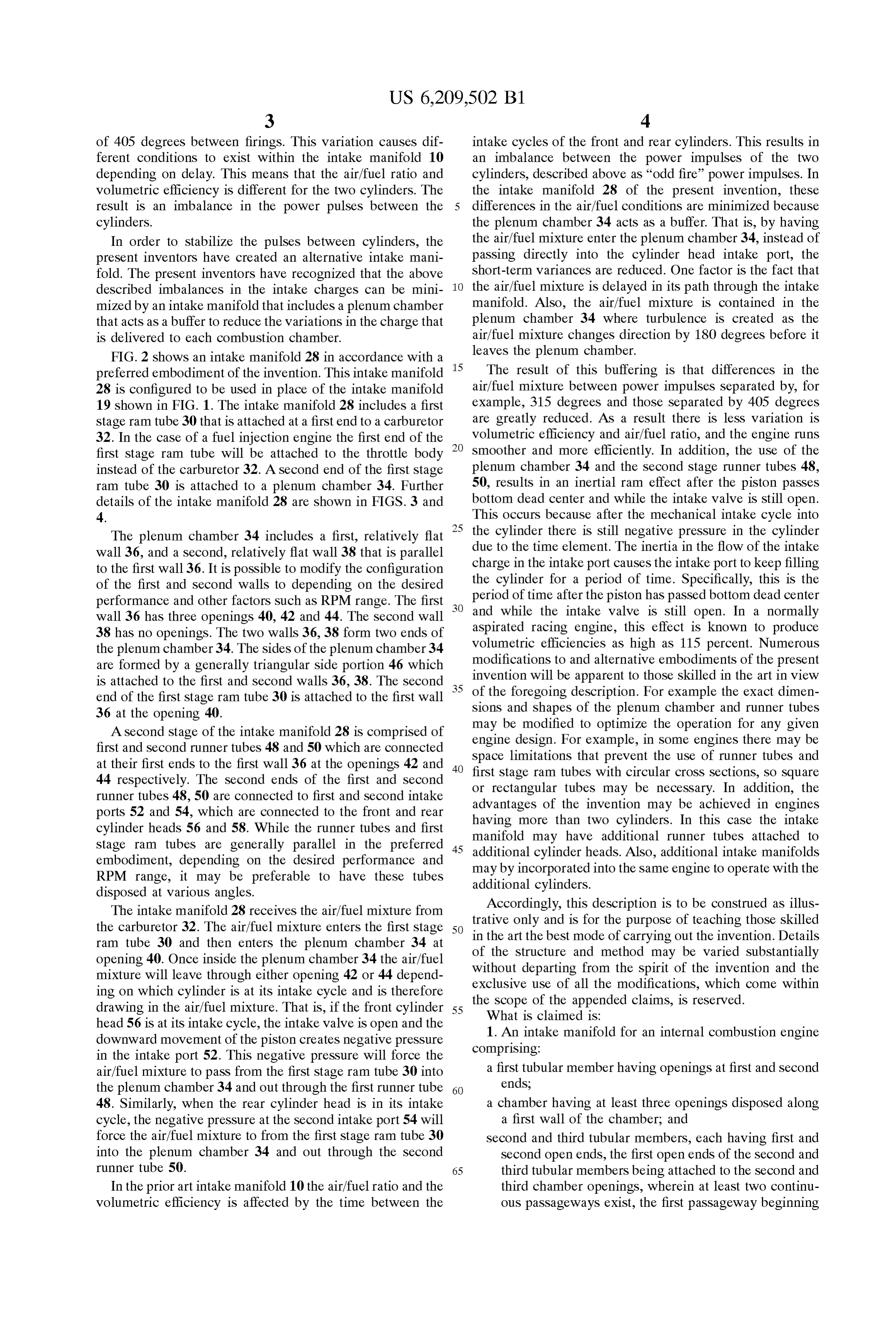
drawing in the air/fuel mixture. That is, if the front cylinder 55 What is claimed is:
head 56 is at its intake cycle, the intake Valve is open and the 1. An intake manifold for an internal combustion engine downward movement of the piston creates negative pressure comprising:
in the intake port 52. This negative pressure will force the air/fuel mixture to pass from the first stage ram tube 30 into a first tubular member having openings at first and Second the plenum chamber 34 and out through the first runner tube 60 ends, 48. Similarly, when the rear cylinder head is in its intake a chamber having at least three openings disposed along cycle, the negative preSSure at the Second intake port 54 will a first wall of the chamber; and force the air/fuel mixture to from the first stage ram tube 30 Second and third tubular members, each having first and into the plenum chamber 34 and out through the Second Second open ends, the first open ends of the Second and runner tube 50. 65 third tubular members being attached to the Second and In the prior art intake manifold 10 the air/fuel ratio and the third chamber openings, wherein at least two continu volumetric efficiency is affected by the time between the Ous passageways exist, the first passageway beginning
Page 6
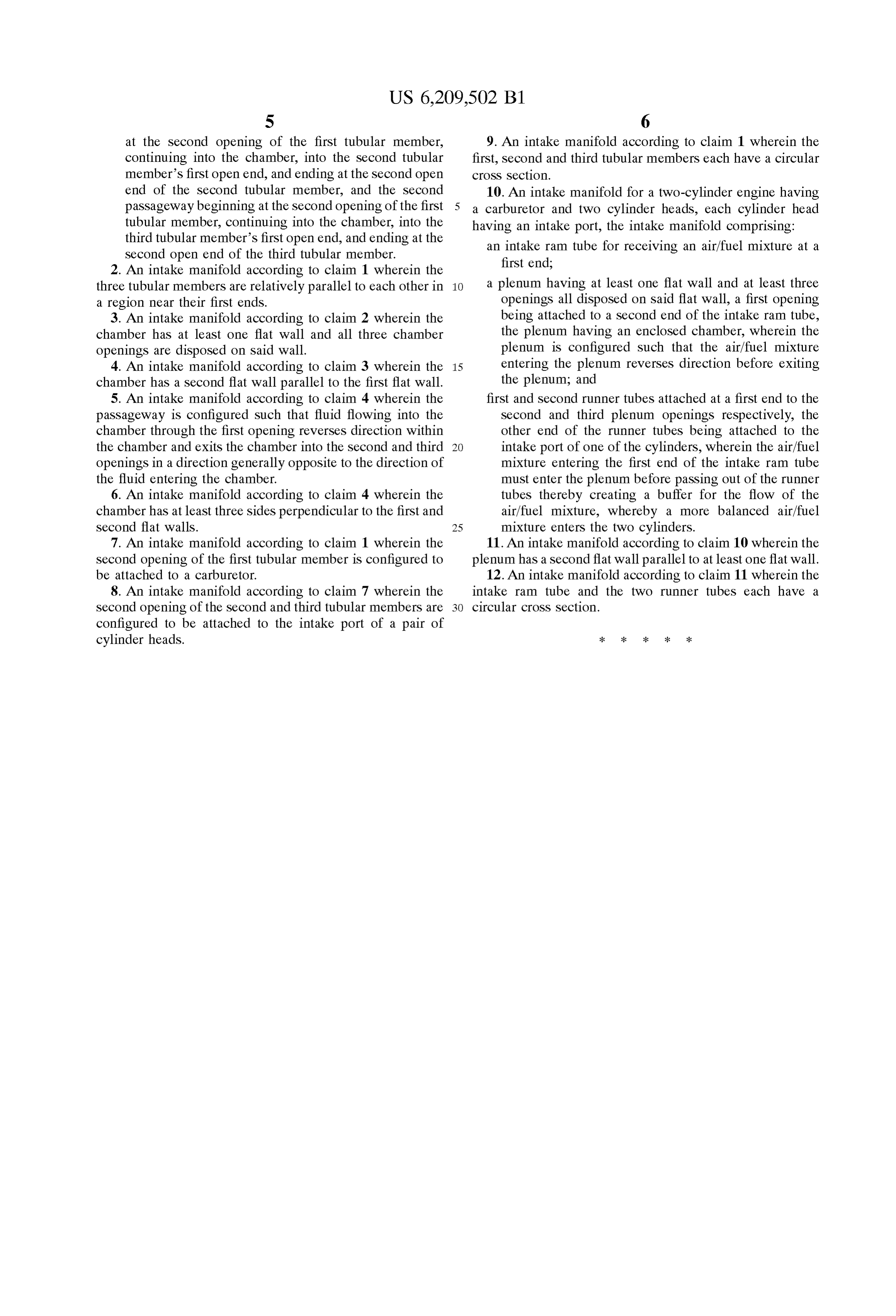
S 6 at the Second opening of the first tubular member, 9. An intake manifold according to claim 1 wherein the continuing into the chamber, into the Second tubular first, Second and third tubular members each have a circular member's first open end, and ending at the Second open croSS Section.
end of the Second tubular member, and the Second 10. An intake manifold for a two-cylinder engine having passageway beginning at the Second opening of the first 5 a carburetor and two cylinder heads, each cylinder head tubular member, continuing into the chamber, into the having an intake port, the intake manifold comprising: third tubular member's first open end, and ending at the an intake ram tube for receiving an air/fuel mixture at a second open end of the third tubular member. first end;
2. An intake manifold according to claim 1 wherein the three tubular members are relatively parallel to each other in a plenum having at least one flat wall and at least three a region near their first ends. openings all disposed on Said flat wall, a first opening 3. An intake manifold according to claim 2 wherein the being attached to a Second end of the intake ram tube, chamber has at least one flat wall and all three chamber the plenum having an enclosed chamber, wherein the openings are disposed on Said wall. plenum is configured Such that the air/fuel mixture 4. An intake manifold according to claim 3 wherein the 15 entering the plenum reverses direction before exiting chamber has a second flat wall parallel to the first flat wall. the plenum; and 5. An intake manifold according to claim 4 wherein the first and Second runner tubes attached at a first end to the passageway is configured Such that fluid flowing into the Second and third plenum openings respectively, the chamber through the first opening reverses direction within other end of the runner tubes being attached to the the chamber and exits the chamber into the second and third intake port of one of the cylinders, wherein the air/fuel openings in a direction generally opposite to the direction of mixture entering the first end of the intake ram tube the fluid entering the chamber. must enter the plenum before passing out of the runner 6. An intake manifold according to claim 4 wherein the tubes thereby creating a buffer for the flow of the chamber has at least three sides perpendicular to the first and air/fuel mixture, whereby a more balanced air/fuel Second flat walls. 25 mixture enters the two cylinders. 7. An intake manifold according to claim 1 wherein the 11. An intake manifold according to claim 10 wherein the Second opening of the first tubular member is configured to plenum has a Second flat wall parallel to at least one flat wall. be attached to a carburetor. 12. An intake manifold according to claim 11 wherein the 8. An intake manifold according to claim 7 wherein the intake ram tube and the two runner tubes each have a Second opening of the Second and third tubular members are circular croSS Section.
configured to be attached to the intake port of a pair of cylinder heads.
Provenance
- Collection
- Cited prior art
- Original PDF
- patentimages.storage.googleapis.com →
- Filed
- 1999-04-06
- Pages
- 6
- Method
- pdftotext (the PDF's own text layer) + pdftoppm 300dpi page scans
- Source
- Google Patents bibliographic record
- Granted
- 2001-04-03
- Inventors
- Gregory G. Davis; Kenneth Thurm
- Transcribed from
- patentimages.storage.googleapis.com →