patent · US5809960
Intake pipe in an internal combustion engine with carburetor
22 September 1998
Page 1 — bibliographic record
United States Patent (19) 11 Patent Number: 5,809,960 Hojyo et al. (45) Date of Patent: Sep. 22, 1998 54 INTAKE PIPE IN AN INTERNAL 4,153,015 5/1979 Hampton ............................ 123/184.46 COMBUSTION ENGINE WITH 5,042,435 8/1991 Feuling ................................... 123/579 CARBURETOR 5,076,218 12/1991 Graziadei .............................. 123/73 V
75 Inventors: Atuo Hojyo; Makoto Harada; Youichi Primary Examiner David A. Okonsky Shihozawa, all of Saitama, Japan Attorney, Agent, or Firm-Birch, Stewart, Kolasch & Birch, LLP 73 Assignee: Honda Giken Kogyo Kabushiki 57 ABSTRACT Kaisha, Tokyo, Japan
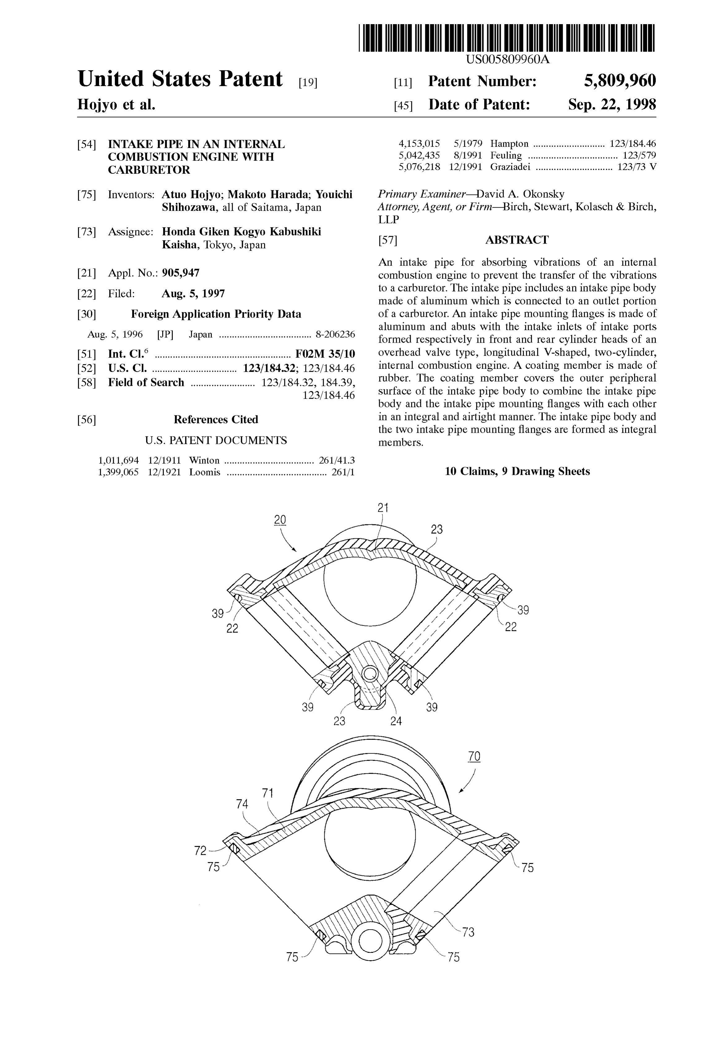
An intake pipe for absorbing Vibrations of an internal 21 Appl. No.: 905,947 combustion engine to prevent the transfer of the vibrations 22 Filed: Aug. 5, 1997 to a carburetor. The intake pipe includes an intake pipe body made of aluminum which is connected to an outlet portion 30 Foreign Application Priority Data of a carburetor. An intake pipe mounting flanges is made of Aug. 5, 1996 JP Japan .................................... 8-206236 aluminum and abuts with the intake inlets of intake ports formed respectively in front and rear cylinder heads of an (51) Int. Cl." ..................................................... F02M 35/10 overhead valve type, longitudinal V-shaped, two-cylinder, 52 U.S. Cl. ................................. 123/184.32; 123/184.46 internal combustion engine. A coating member is made of 58 Field of Search ......................... 123/18432, 184.39, rubber. The coating member covers the outer peripheral 123/184.46 Surface of the intake pipe body to combine the intake pipe body and the intake pipe mounting flanges with each other 56) References Cited in an integral and airtight manner. The intake pipe body and the two intake pipe mounting flanges are formed as integral
1,011,694 12/1911 Winton ................................... 261f41.3 1,399.065 12/1921 Loomis ....................................... 261/1 10 Claims, 9 Drawing Sheets
Page 2
Drawing sheet — no readable text.
Page 3
Drawing sheet — no readable text.
Page 4
Drawing sheet — no readable text.
Page 5
Drawing sheet — no readable text.
Page 6
Drawing sheet — no readable text.

Page 7
Drawing sheet — no readable text.
Page 8
Drawing sheet — no readable text.
Page 9
Drawing sheet — no readable text.
Page 10
Drawing sheet — no readable text.
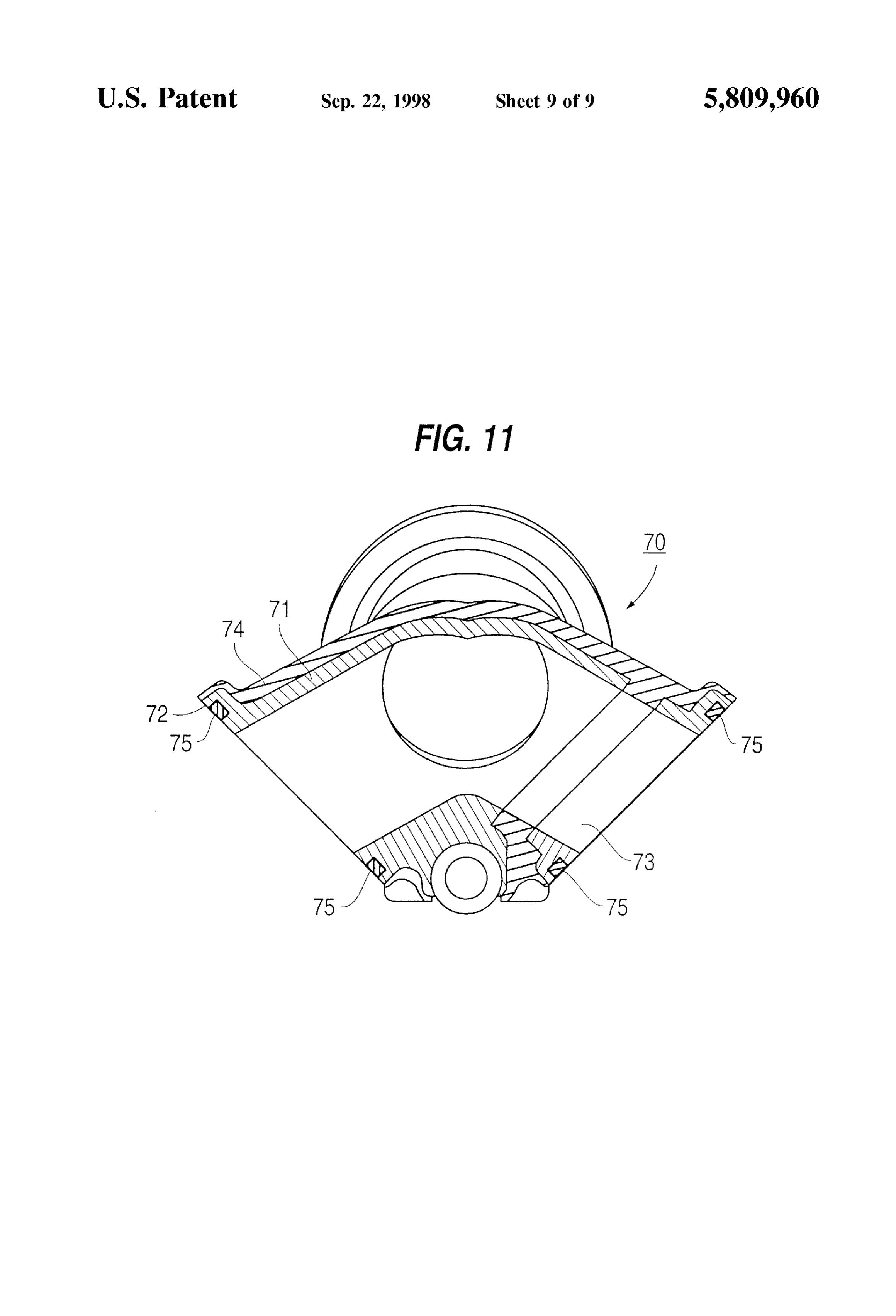
Page 11
INTAKE PIPE IN AN INTERNAL through the intake passage without causing disturbance and COMBUSTION ENGINE WITH thus the intake pipe of the invention can contribute to CARBURETOR maintaining the output and efficiency of the internal com bustion engine at a high level.
BACKGROUND OF THE INVENTION In the present invention, moreover, Since the metallic 1. Field of the Invention intake pipe body is combined integrally with the carburetor and the metallic intake pipe mounting flange is combined
The present invention relates to an intake pipe for absorb integrally ing vibrations of an internal combustion engine equipped combined together with the internal combustion engine and are with a carburetor to prevent the vibrations from being Vibrations using an elastic member, the transfer of transmitted to the carburetor. from the internal combustion engine to the car buretor is prevented. The normal operation of the carburetor 2. Description of Background Art is ensured and the durability thereof is improved. In a conventional internal combustion engine with a According to the present invention, Vibrations of plural carburetor there usually is employed an intake pipe con cylinders are prevented from being transferred to each other Structed of the same material as that of a metallic cylinder 15 and an unfavorable influence on the carburetor and each head formed with an intake port. The carburetor is connected cylinder caused by mutual interference of Such vibrations is to an upstream end of the intake pipe, while the intake port avoided.
formed in the cylinder head is connected to a downstream According to the present invention vibrations of cylinders end of the intake pipe. Therefore, Vibrations generated in the mounted internal combustion engine are apt to be transmitted to the transferredSeparately in a crank case are prevented from being to each other.
carburetor through the highly rigid intake pipe.
In a multi-cylinder internal combustion engine, especially ofAccording the internal to the present invention, at the time of Start-up combustion engine or during operation at a a V-shaped internal combustion engine, equipped with a low temperature, carburetor, the cylinder heads of the cylinders each Some 25 metallic intake pipehotbody water can be introduced into the time vibrate independently. In the case where a downstream accelerate the vaporizationtoofheat the body. It is possible to portion of an intake pipe is connected at an upstream end to maintain the combustion in a stablein State fuel the air-fuel mixture to and improve the a single carburetor and is branched into plural intake pipes, low temperature performance.
vibrations of the cylinder head of one cylinder and that of the cylinder head of another cylinder are transferred to each to Further,further according to the present invention, it is possible improve the air tightness of the intake System.
other through the highly rigid intake pipes and are apt to interfere with each other. Further scope of applicability of the present invention will In an effort to avoid Such inconvenience there has been become apparent from the detailed description given here proposed an internal combustion engine in which an intake inafter. However, it should be understood that the detailed pipe is formed of a highly elastic material Such as rubber. In 35 description and Specific examples, while indicating pre Such an internal combustion engine, Vibrations are absorbed, ferred embodiments of the invention, are given by way of but due to insufficient rigidity it is impossible to firmly illustration only, Since various changes and modifications Support the weight of a carburetor or accommodate a nega within the spirit and scope of the invention will become tive intake pressure. This may make it impossible to retain tion. apparent to those skilled in the art from this detailed descrip a required shape for fresh air to flow Smoothly. In addition, 40 air cannot be fed in a uniformly dispersed State to each BRIEF DESCRIPTION OF THE DRAWINGS cylinder.
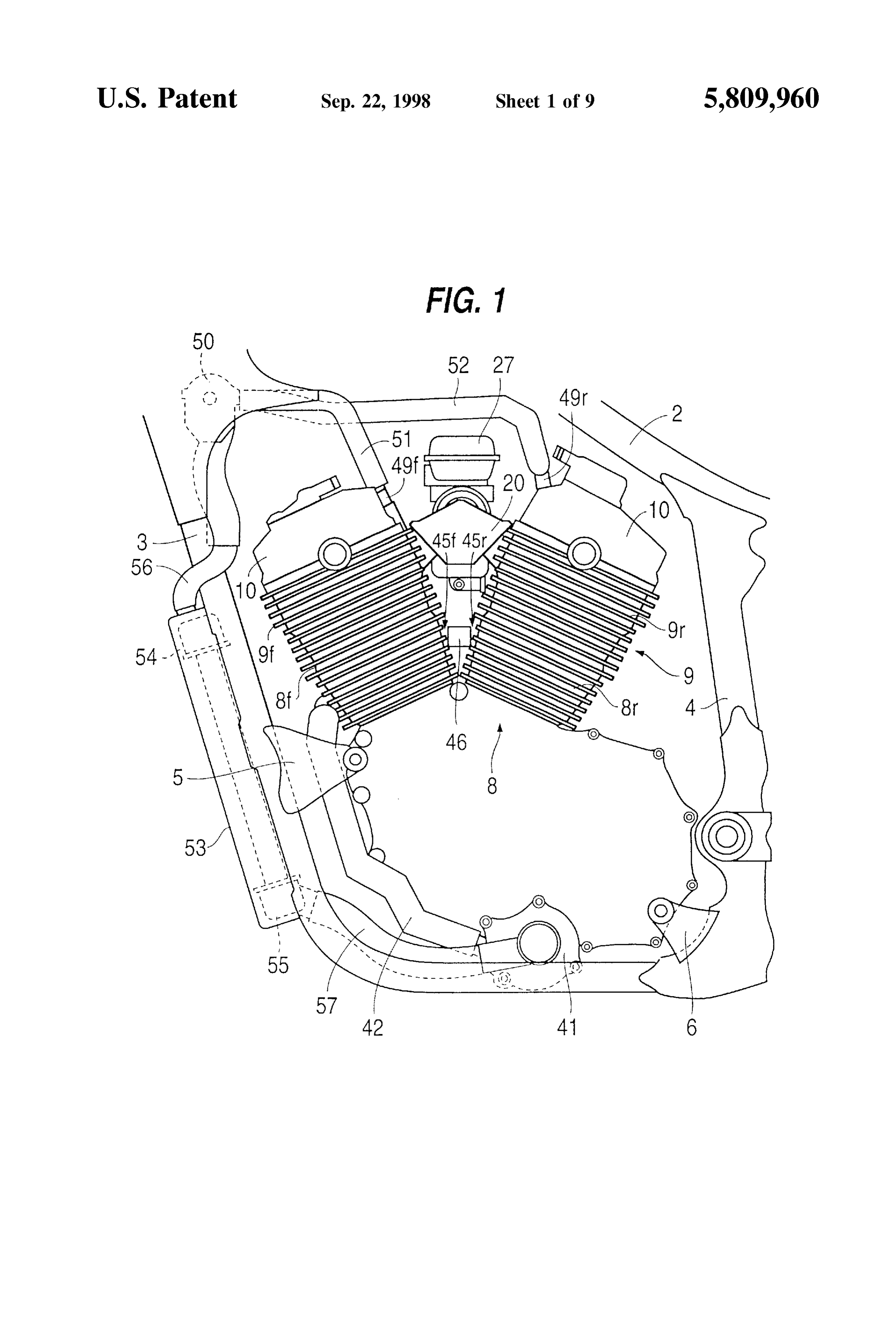
According to the present invention, an intake pipe for an The present invention will become more fully understood internal combustion engine with a carburetor is provided from the detailed description given hereinbelow and the which overcomes the above-mentioned problem. The intake 45 accompanying drawings which are given by way of illus pipe connects between an intake outlet of the carburetor and tration only, and thus are not limitative of the present an intake inlet of an intake port in the internal combustion invention, and wherein:
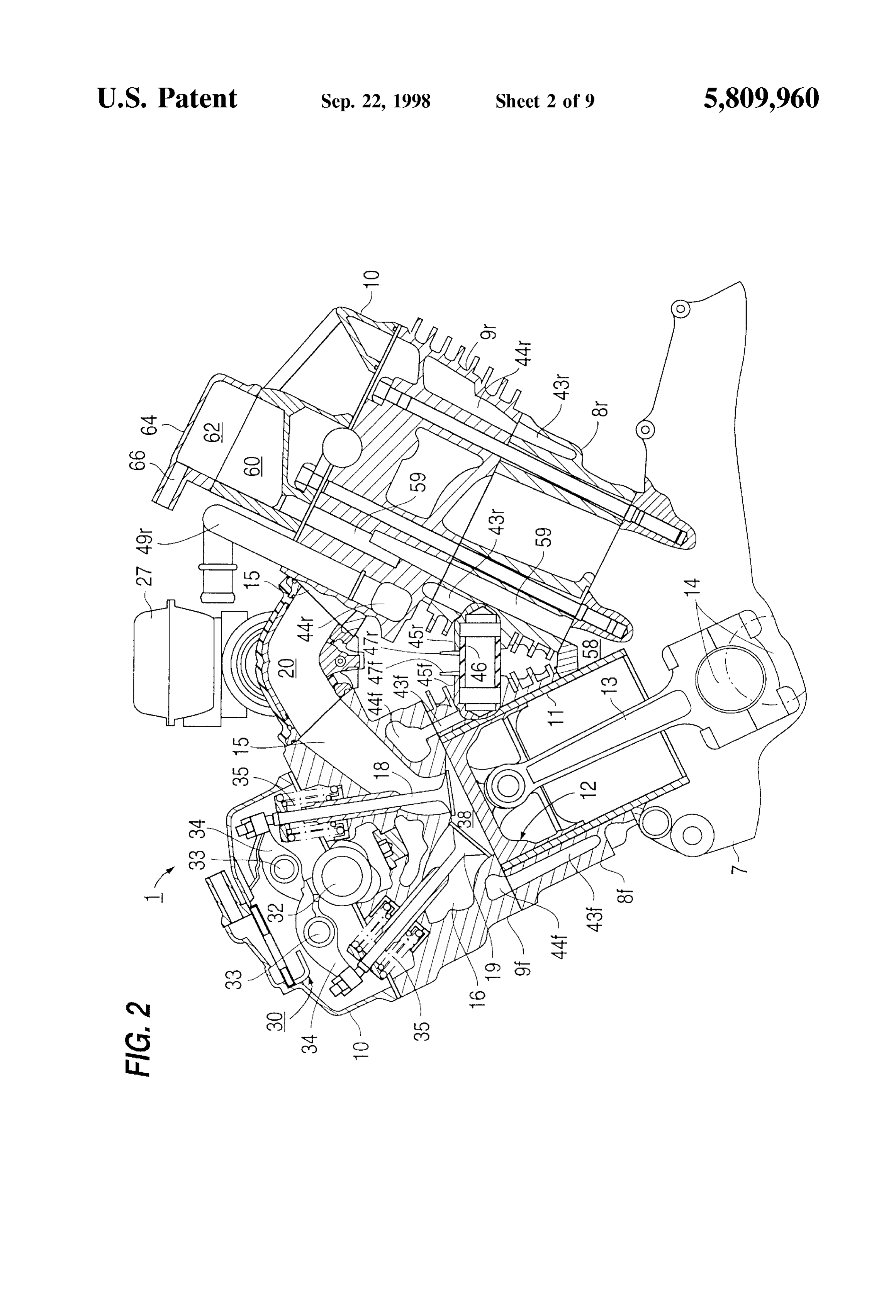
engine. A metallic intake pipe body is connected to the FIG. 1 is a side view of an internal combustion engine intake outlet of the carburetor and a metallic intake pipe equipped with a carburetor and also equipped with an intake mounting flange is brought into abutment with the intake 50 pipe Structure embodying the present invention; inlet of the intake port in the internal combustion engine. FIG. 2 is a longitudinal Sectional Side view showing a The metallic intake pipe body and the metallic intake pipe principal portion of the internal combustion engine illus mounting flange are separate members and are combined trated in FIG. 1;
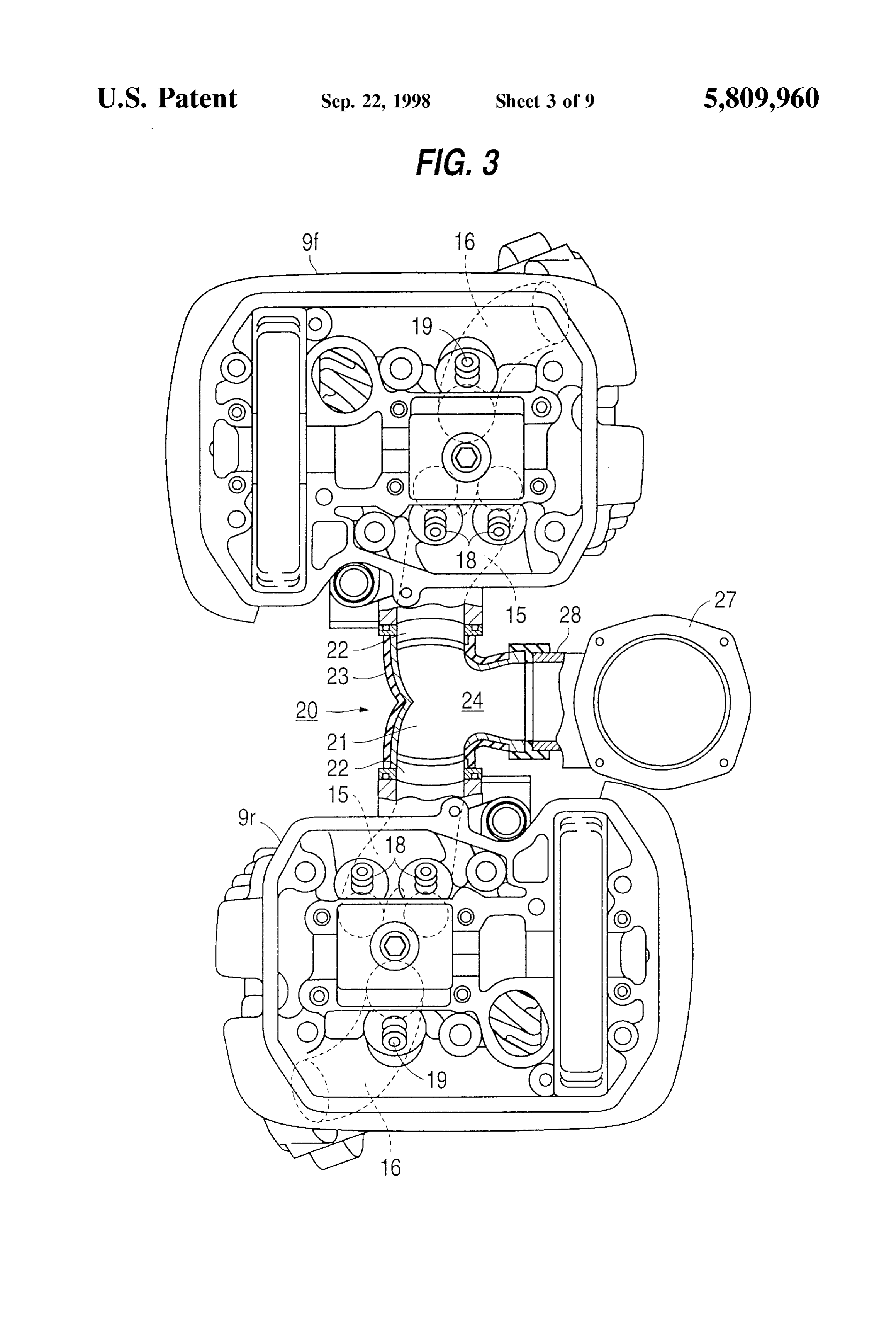
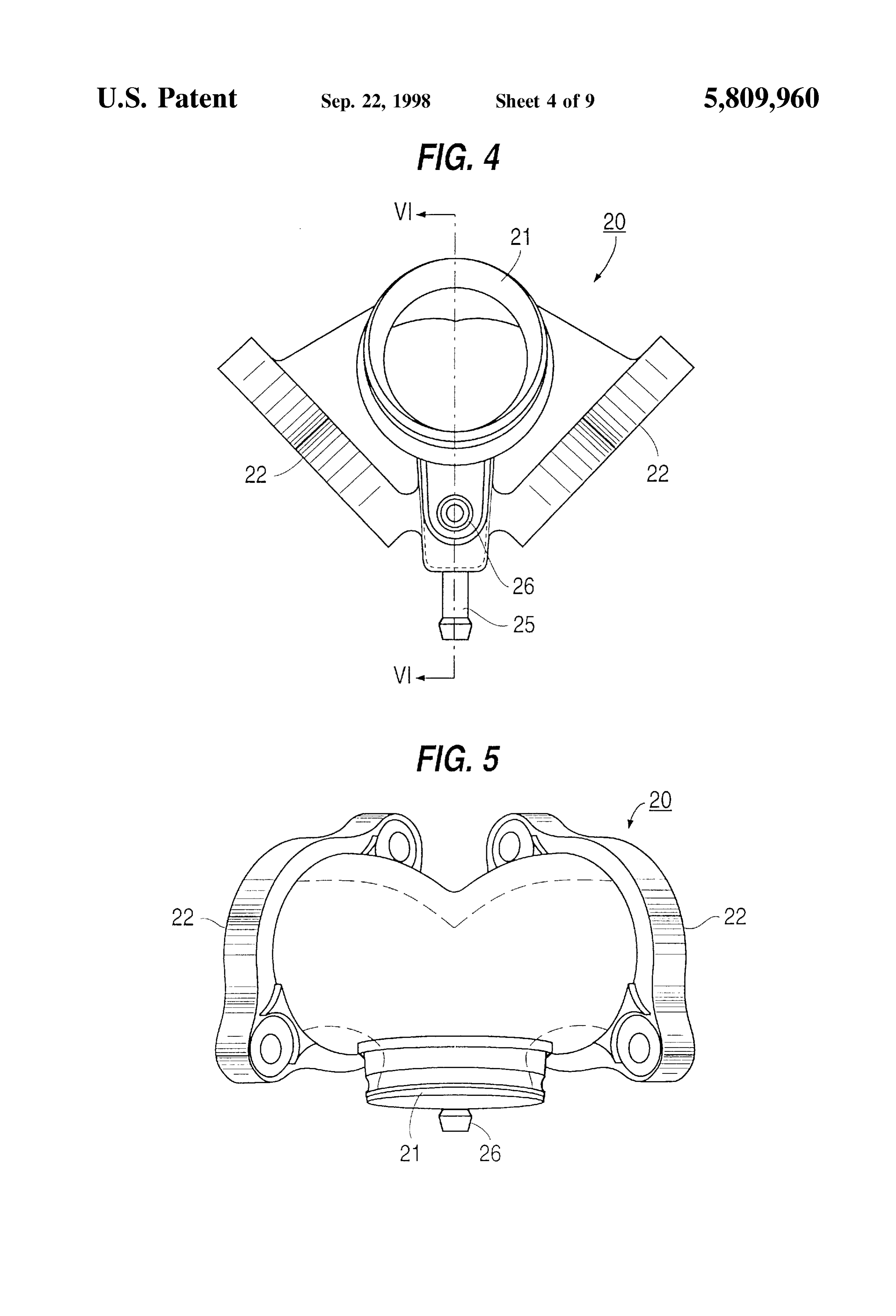
together in an airtight and integral manner using an elastic FIG. 3 is a plan view of the internal combustion engine member which covers the outer peripheral Surface of the 55 illustrated in FIG. 1 with a head cover removed and the metallic intake pipe body. intake pipe shown in a partially cut-away State; Since the present invention is constructed as above, even if the intake pipe is formed of a different material, an airtight to FIG.
the 4 is a front view of the intake pipe structure attached internal combustion engine shown in FIG. 1;
Structure is attained. The discharge of an air-fuel mixture into the atmosphere and the mixing of air contained in the 60 FIG. 5 is a plan view of FIG. 4; FIG. 6 is a cross-sectional view taken on line VI-VI in atmosphere into the air fuel mixture which is Set to a desired air-fuel ratio, are prevented. FIG. 4;
In the present invention, Since the intake pipe body is FIG. 7 is a longitudinal sectional view taken on line formed of a highly rigid metal, a required shape of an intake VII-VII in FIG. 6;
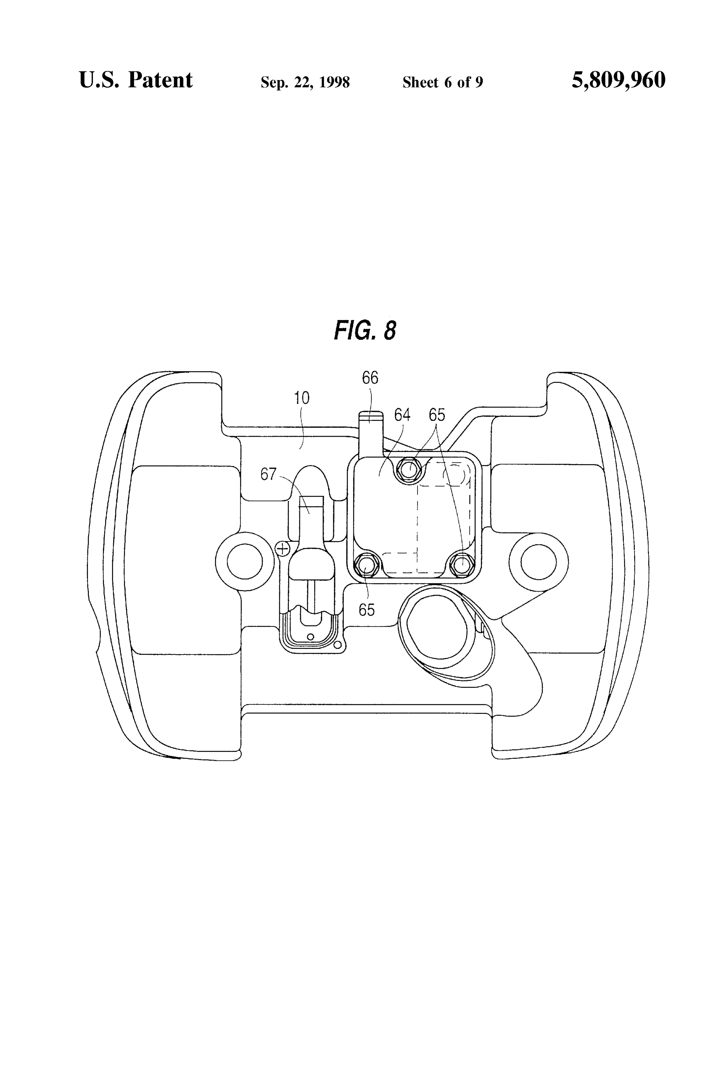
passage is ensured even when the intake pipe undergoes 65 FIG. 8 is a plan view of a cylinder head in the internal Vibrations from the internal combustion engine or a negative combustion engine shown in FIG. 1;
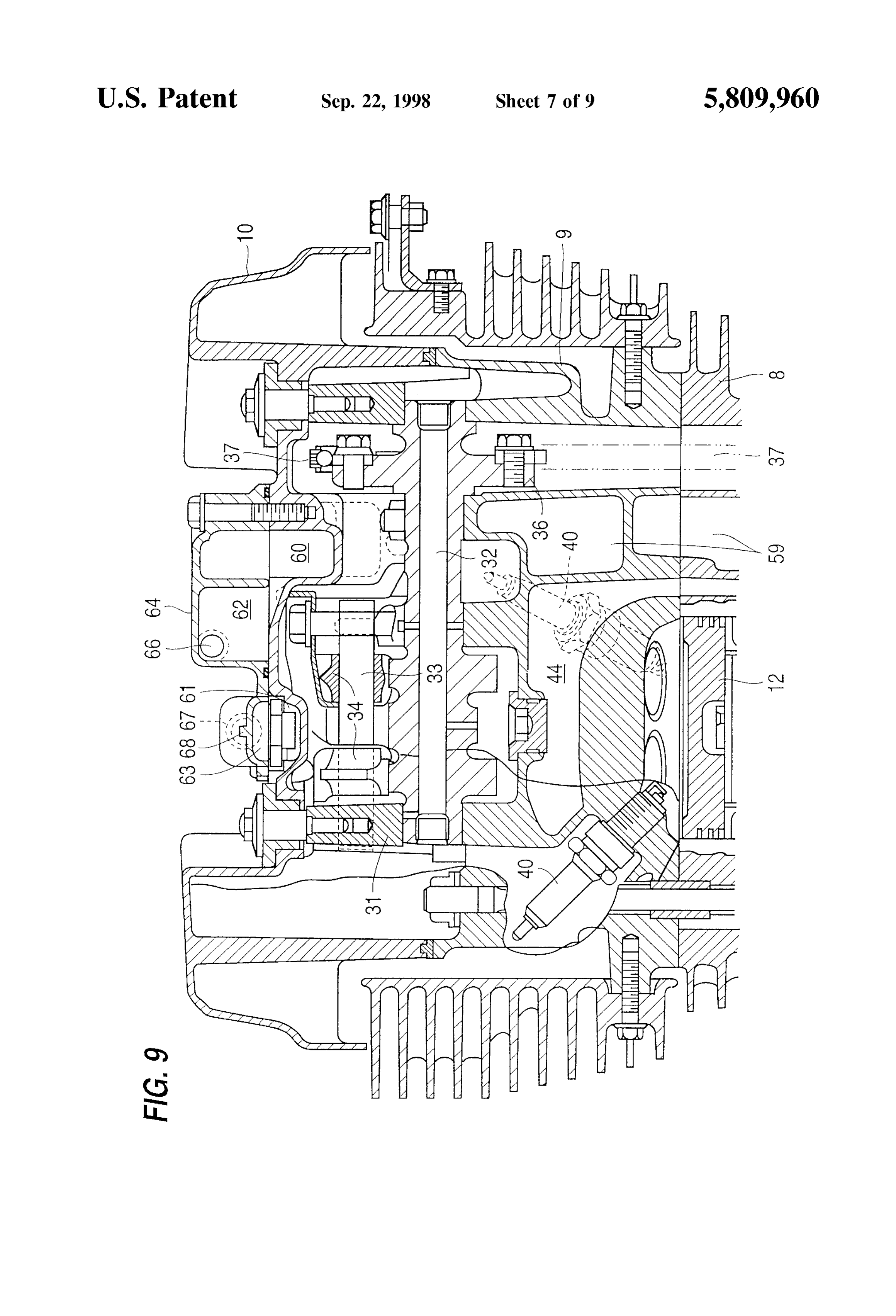
intake pressure. Consequently, intake air can flow Smoothly FIG. 9 is a longitudinal sectional view of FIG.8;
Page 12
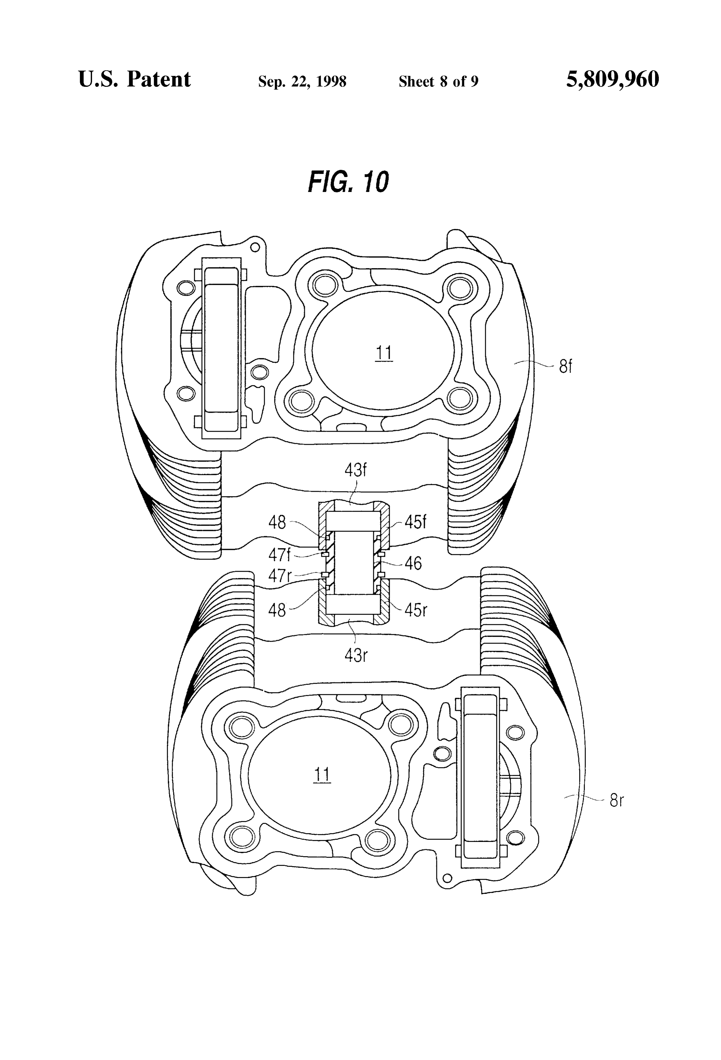
FIG. 10 is a plan view similar to FIG. 3, showing water integral manner. The intake pipe body 21 and the two intake pipes and a connecting pipe in longitudinal Section; and pipe mounting flanges 22 are formed as Separate members FIG. 11 is a longitudinal Sectional view showing another and are fitted into a mold. Crude rubber is charged into a embodiment of the present invention. clearance of the mold, followed by Vulcanization under heating and pressure, to produce the intake pipe 20.
DETAILED DESCRIPTION OF THE
PREFERRED EMBODIMENTS
A cooling water passage 24 is formed in the aluminum intake pipe body 21, and a cooling water inlet joint is fitted
An embodiment corresponding to the invention is illus in an opening formed in the lower end of the intake pipe trated in FIGS. 1 to 10. An overhead valve type, longitudinal body 21. An opening is formed in the carburetor 27 side end V-shaped, two cylinder 4-stroke, internal combustion engine portion of the intake pipe body 21 and is fitted with a cooling 1 is mounted through brackets 5 and 6 on a down tube 3 and water outlet joint 26. Further, on the abutment face of each a center frame 4 Suspended, respectively, from front and rear intake pipe mounting flange 22 for abutment with the portions of a main frame 2 of a two-wheeled motor vehicle. cylinder heads 9f and 9r is formed an annular groove In the internal combustion engine 1, a cylinder 8, including 15 throughout the whole circumference of the abutment face. a front cylinder 8f and a rear cylinder 8r; and a cylinder head Packing material 39 is fitted in the annular groove. 9, including a front head 9f and a rear head 9r, are succes At the lower portion of the crank case 7 on the left-hand Sively Superposed together above a crankcase 7 at a cylinder side of the vehicle body, as shown in FIG. 1, there is angle of about 52 and are combined together. The crank disposed a cooling water pump 41 which is rotated by the case 7, cylinders 8f and 8r and cylinder heads 9f and 9r are crank Shaft 14. A cooling water Supply pipe 42 is connected made of aluminum or an aluminum alloy, and the outer to a discharge port of the cooling water pump 41. The upper peripheral portion of a cylinder bore 11 of the cylinders 8f end of the cooling water Supply pipe 42 is connected to a and 8r is made of cast iron. The upper portion of the cylinder cooling water passage 43f formed in the front lower portion heads 9f and 9r is covered with a head cover 10. of the front cylinder 8f
A piston 12 is inserted vertically slidably into the cylinder The front cooling water passage 43f of the front cylinder bore 11 of the cylinders 8f and 8r. The piston 12 and a crank 25 8f and a front cooling water passage 44f formed in the front shaft 14 extend in the transverse direction of the vehicle and cylinder heads 9f and 9r are in communication with each are interconnected with a connecting rod 13. The crankshaft other. Likewise, a rear cooling water passage 43r formed in 14 is rotated with vertical movement of the piston 12. the rear cylinder 8r and a rear cooling water passage 44r An intake port 15 is branched right and left in a bifurcated formed in the rear cylinder head 9r are also in communica shape at its downstream portion and is formed in the cylinder tion with each other. As shown in FIG. 10, water pipes 45f heads 9f and 9r at a position on the cylinder angle side of the and 45r project in a longitudinally aligned relation to each cylinders 8f and 8r. At a position on the opposite side there other at positions where the front and rear cylinders 8f, 8r are is formed an exhaust port 16 in the cylinder heads 9f and 9r. opposed to each other. A connecting pipe 46 is made of To an upstream opening of the intake port 15 is Secured an 35 rubber and is inserted into the water pipes 45f and 45r. intake pipe mounting aluminum flange 22 of a bifurcated Further, at front end positions of the water pipes 45f and 45r, intake pipe 20 with bolts (not shown). A flange for mounting ring-like clips 47f and 47r are fitted in recesses formed in the an exhaust pipe (not shown) is integrally fixed to a down outer periphery of the connecting pipe 46. At positions close Stream opening of the exhaust port 16. to the base ends of the water pipes, O-rings 48 are fitted on Further, an intake valve 18 and an exhaust valve 19 are a the connecting pipe. Thus, the water pipes 45f and 45r are disposed in the intake port 15 and the exhaust port 16, connected with each other in a water tight manner. respectively, on the cylinder bore 11 side. A valve operating As shown in FIG. 1, moreover, cooling water pipes 49f mechanism 30, for opening and closing the intake valve 18 and 49r communicating with the cooling water passages 44f and the exhaust valve 19, includes a camshaft 32 which is and 44r, respectively, and are fitted in the tops of the Supported rotatably by a camshaft holder 31 in parallel with 45 cylinder heads 9f and 9r. The cooling water pipe 49f and a the crank shaft 14. A rocker arm 34 is supported pivotably thermostat 50 are connected with each other through a by a rocker arm shaft 33 which is parallel to the camshaft rubber hose 51. The cooling water pipe 49r and the ther 32, a valve spring 35 urges the intake valve 18 and the mostat 50 are connected together through a rubber hose 52. exhaust valve 19 in their closed directions at all times. A Further, an upper tank 54 of a radiator 53 is disposed along driven Sprocket 36 is integral with the camshaft holder 31. So the down tube 3 and the thermostat 50 and is connected A driving Sprocket is integral with the crank Shaft 14. An together through a rubber hose 56. A lower tank 5.5 of the endless chain 37 is entrained on the driven sprocket 36. The radiator 53 and a Suction portion of the cooling water pump camshaft 32 is rotated at a Speed which is half of the rotating 41 are connected together through a rubber hose 57. When speed of the crankshaft 14, whereby the intake valve 18 and the water temperature is below a predetermined temperature, the exhaust valve 19 are driven in an opening and closing ss a valve of the thermostat 50 is closed to stop the discharge motion at a timing of one rotation at every two rotations of of cooling water to the upper tank 54 of the radiator 53 the crank shaft 14. through the rubber hose 56.
Spark plugs 40 are disposed respectively in the vicinity of In the head cover 10, as shown in FIGS. 2 and 9, there are two intake valves 18. formed a lower breather recess 60 communicating with a As shown in FIG. 3, the intake pipe 20 includes an intake 60 crank chamber 58 in the crank case 7 through a breather pipe body 21 made of aluminum and connected to an outlet passage 59 and a lower Secondary air receSS 61 communi portion 28 of a carburetor 27. Intake pipe mounting flanges cating with the exhaust port 16 in the cylinder heads 9f and 22 are made of aluminum and abut with intake inlets of 9r through a secondary air passage (not shown). On the other intake ports 15 formed in front and rear cylinder heads 9f, 9r, hand, an upper breather receSS 62 and an upper Secondary air and a coating member 23 made of rubber for combining the 65 receSS 63 in an opposed relation to the lower breather receSS aluminum intake pipe body 21 and the aluminum intake pipe 60 and the lower Secondary air receSS 61, respectively, are mounting flanges 22 with each other in an airtight and formed in a cover member 64. The cover member 64 is
Page 13
S 6 integrally fixed to the head cover 10 with bolts 65. The lower between both intake pipe mounting flanges 22, Vibrations of and upper breather recesses 60, 62 and the lower and upper the cylinders 8f and 8r in the overhead valve type, longitu secondary air recesses 61, 63 form a breather chamber and dinally V-shaped, two-cylinder, internal combustion engine a secondary air chamber, respectively. Joints 66 and 67 are 1 are also absorbed by the intake pipe mounting flanges 22. fitted in the upper breather receSS 62 and the upper Second Thus, the transfer of vibrations from the cylinders 8f and 8r ary air receSS 63, respectively, and are connected to an air to the carburetor 27 is suppressed, whereby not only the cleaner (connected upstream of the carburetor 27 though not carburetor 27 can operate normally without being affected shown) through a rubber hose (not shown). A reed valve 68 by the vibrations but also improved durability can be which only permits the passage of Secondary air to the lower attained.
Secondary air receSS 61 from the upper Secondary air receSS When the cooling water temperature rises and the valve of 63 is disposed in the joint portion between the lower the thermostat 50 is opened, the cooling water discharged Secondary air receSS 61 and the upper Secondary air receSS from the cooling water pump 41 is fed to the cooling water 63. passage 43f in the front cylinder 8f through the cooling water Since the embodiment illustrated in FIGS. 1 to 10 are Supply pipe 42. A portion of the cooling water flowing constructed as above, when the overhead valve type, longi 15 through the cooling water passage 43f passes through the tudinally V-shaped, two-cylinder, internal combustion front cooling water passage 44f in the front cylinder head 9f engine 1 is in operation, intake air is filtered by means of an and reaches the thermostat 50 through the front cooling air cleaner (not shown). Thereafter fuel is fed by means of water pipe 49f and the rubber hose 51. The remaining the carburetor 27 and is mixed with the intake air at a portion of the cooling water flowing through the front required air-fuel ratio, then the mixture passes through the cooling water passage 43f flows into the cooling water intake pipe 20 and flows into the intake port 15 in the passage 43r in the rear cylinder 8r through both connection cylinder heads 9f and 9r. Then when the intake valve 18 is pipe 46 and rear water pipe 45r. The cooling water then opened in the Suction Stroke, the mixture is Sucked into a passes through the cooling water passage 44r in the rear combustion chamber 38 formed in the upper portion of the cylinder head 9r and reaches the thermostat 50 through both cylinder bore 11. 25 rear cooling water pipe 49r and rubber hose 52. Both cooling
Thereafter, near the final Stage of the compression Stroke, water portions join together in the thermostat 50. The joined the mixture in the combustion chamber 38 is ignited by the cooling water flows into the upper tank 54 of the radiator 53 spark plug 40, and the exhaust valve 19 is opened in the through the rubber hose 56 and then flows into the lower exhaust Stroke which follows the expansion Stroke, whereby tank 5.5 through a tube (not shown) of the radiator 53 while combustion gas is discharged through an exhaust pipe and a it is cooled with cooling air and is returned to the Suction muffler (neither shown). port of the cooling water pump 41 from the lower tank 5.5 In this operating condition, even if a throttle valve (not through the rubber hose 57.
shown) is throttled to increase the negative intake pressure, Blow-by gas present in the crank chamber 58 of the crank since the outer periphery of the aluminum body 21 of the case 7 flows through the breather passage 59 into the intake pipe 20 and the intake pipe mounting flange 22 are 35 breather chamber formed by both lower breather recess 60 made of aluminum and the connection of the two are coated and upper breather receSS 62. The blow-by gas is then is with the coating member 23 made of rubber, the coating conducted to the air cleaner through both joint 66 and a member 23 is pressed Strongly against both intake pipe body rubber hose (not shown). Further, the air present within the 21 and intake pipe mounting flange 22 due to a preSSure air cleaner flows into the upper Secondary air receSS 63 difference between the atmospheric pressure and the nega 40 through both a rubber hose (not shown) and joint 67. This air tive intake pressure. Besides, the coating member 23 made is then conducted to the lower Secondary air receSS 61 of rubber is present on the outer periphery of the connection through the reed valve 68 and is fed as secondary air to the between the intake pipe body 21 and the intake pipe mount exhaust port 16 through a secondary air passage (not ing flange 22. Therefore, airtightness is ensured firmly and shown).
the entry of atmospheric air into the intake pipe 20 is 45 The lower and upper breather recesses 60, 62 are formed prevented. in the head cover 10, while the lower and upper secondary Moreover, Since the greater part of the intake pipe 20 is air recesses 61, 63 are formed in the cover member 64. By constituted by both a highly rigid intake pipe body 21 made merely combining the cover member 64 with the head cover of aluminum and an intake pipe mounting flange 22 also 10 integrally using bolts 65 both breather chamber and made of aluminum, even if Such a pressure difference 50 secondary air chamber are formed. Therefore, the number of between the atmospheric pressure and the negative intake components and the required Steps for assembly are preSSure as mentioned above is exerted on the intake pipe decreased and thus a reduction in cost can be attained. 20, the intake passage shape in the intake pipe 20 does not Although in the embodiment illustrated in FIGS. 1 to 10 change and can be maintained in its original shape. AS a both upper breather receSS 62 and upper Secondary air receSS result, the air-fuel mixture is fed uniformly into front and 55 63 are formed in a single cover member 64, the cover rear combustion chambers 38f, 38r without causing distur member may be divided into two cover members and the bance. Thus, a uniform operating condition is ensured by recesses 62 and 63 may be formed respectively in the thus both front and rear cylinders 8f, 8r. divided cover members.
Since the front and rear cylinders 8f, 8r are mounted Although in the embodiment illustrated in FIGS. 1 to 10, Separately to the crank case 7, each of the cylinderS 8f and 60 the intake pipe 20 is composed of a Single intake pipe body 8r vibrates independently. Even if the distance between open 21 made of aluminum, two intake pipe mounting flanges 22 ends of intake ports 15f and 15r in the cylinders 8f and 8r made of aluminum, and a coating member made of rubber varies, this variation of the distance is absorbed by the which coats both intake pipe body 21 and flange 22 may be coating member 23 made of rubber of the intake pipe 20, and constructed according to the present invention as illustrated the vibrations of the cylinders 8f and 8r are also suppressed. 65 in FIG. 11.
Further, Since the intake pipe body 21 connected inte In an intake pipe 70 shown in FIG. 11, an intake pipe body grally with the carburetor 27 is in an intervened state 71 made of aluminum is designed to be connected to an
Page 14
intake outlet of the carburetor 27 and an intake pipe mount intake outlet of the carburetor and an intake inlet of an intake ing flange 72 made of aluminum abuts with the intake inlet port in the internal combustion engine, comprising: of the intake port 15f in the front cylinder head 9fare formed a multi-cylinder internal combustion engine including a integrally with each other and are brought into abutment plurality of cylinders, with the intake inlet of the intake port 15r in the rear cylinder 5 a metallic intake pipe body connected to the intake outlet head 9r. An intake pipe mounting flange 73 made of of the carburetor, Said metallic intake pipe body includ aluminum is formed separately from the intake pipe body 71 ing an integral type metallic intake pipe mounting and the intake pipe mounting flange 72. The intake pipe flange abutting with an intake inlet of an intake port of body 71 and the intake pipe mounting flanges 72 and 73 are any one of the plurality of cylinders, a separate type combined together in an integral and airtight manner using metallic intake pipe mounting flange for abutting with a coating member 74 made of rubber which covers the outer an intake inlet of an intake port of any other of the peripheral Surface of the intake pipe body 71. Packing 75 is plurality of cylinders other than the cylinder connected fitted in each of the abutting end faces of the intake pipe to the integral type metallic intake pipe mounting mounting flanges 72 and 73. flanges;
15 Said mettalic intake pipe mounting flange and Said metal
In the intake pipe 70 illustrated in FIG. 11, since the front lic intake pipe body being Separate members, and and rear intake pipe mounting flanges 72 and 73 made of an elastic member for covering an outer peripheral Surface aluminum are combined together through the coating mem of the metallic intake pipe body and Said Separate ber 74 made of rubber, there does not occur any interference metallic intake pipe mounting flange for combining caused by mutual vibrations transferred between the front Said metallic intake pipe body and Said Separate metal cylinder 8f, cylinder head 9f and the rear cylinder 8r, lic intake pipe mounting flange together in an airtight cylinder head 9r. Consequently, excessive vibrations are and integral manner.
prevented from being exerted on the carburetor 27 and hence 3. The intake pipe for an internal combustion engine with the carburetor 27 is prevented from being impaired its a carburetor according to claim 2, wherein Said multicylin function and durability.
25 der internal combustion engine is a V-shaped internal com
Since the intake pipe body 71 and the intake pipe mount bustion engine.
ing flange 72 are rendered integral with each other, the 4. The intake pipe for an internal combustion engine with number of components required is decreased and it becomes a carburetor according to claim 1, wherein a hot water possible to attain a reduction in the cost of manufacture. passage is formed within Said metallic intake pipe body. Although in the above embodiments the present invention 5. The intake pipe for an internal combustion engine with has been applied to a V-shaped internal combustion engine, a carburetor according to claim 2, wherein a hot water it goes without Saying that the invention is also applicable to passage is formed within Said metallic intake pipe body. a Straight multi-cylinder internal combustion engine or a 6. The intake pipe for an internal combustion engine with Single-cylinder internal combustion engine. a carburetor according to claim 3, wherein a hot water The invention being thus described, it will be obvious that 35 passage is formed within Said metallic intake pipe body. the same may be varied in many ways. Such variations are 7. The intake pipe for an internal combustion engine with not to be regarded as a departure from the Spirit and Scope a carburetor according to claim 1, wherein a Sealing member of the invention, and all Such modifications as would be is provided on an abutment face of Said metallic intake pipe obvious to one skilled in the art are intended to be included mounting flange for abutment with the internal combustion within the Scope of the following claims. 40 engine, Said Sealing member being provided throughout the What is claimed is: whole circumference of Said abutment face. 1. An intake pipe for an internal combustion engine with 8. The intake pipe for an internal combustion engine with a carburetor, Said intake pipe providing a connection a carburetor according to claim 2, wherein a Sealing member between an intake outlet of the carburetor and an intake inlet is provided on an abutment face of Said metallic intake pipe of an intake port in the internal combustion engine, com 45 mounting flange for abutment with the internal combustion prising: engine, Said Sealing member being provided throughout the a metallic intake pipe body connected to the intake outlet whole 9.
circumference of Said abutment face.
The intake pipe for an internal combustion engine with of the carburetor;
a carburetor a metallic intake pipe mounting flange positioned in is provided on according to claim3, wherein a Sealing member an abutment face of Said metallic intake pipe abutment with the intake inlet of the intake port in the 50 mounting flange for abutment with the internal combustion internal combustion engine; engine, Said Sealing member being provided throughout the Said metallic intake pipe body and Said metallic intake whole circumference of Said abutment face.
pipe mounting flange being Separate members, and 10. The intake pipe for an internal combustion engine an elastic member for covering an Outer peripheral Surface 55 with a carburetor according to claim 4, wherein a Sealing of the metallic intake pipe body for combining the member is provided on an abutment face of Said metallic metallic intake pipe mounting flange and Said metallic intake pipe mounting flange for abutment with the internal intake pipe body together in an airtight and integral combustion engine, Said Sealing member being provided C. throughout the whole circumference of Said abutment face. 2. An intake pipe for an internal combustion engine with a carburetor having an intake pipe connected between an k k k k k
Provenance
- Collection
- Cited prior art
- Original PDF
- patentimages.storage.googleapis.com →
- Filed
- 1997-08-05
- Pages
- 14
- Method
- pdftotext (the PDF's own text layer) + pdftoppm 300dpi page scans
- Source
- Google Patents bibliographic record
- Granted
- 1998-09-22
- Inventors
- Atuo Hojyo; Makoto Harada; Youichi Shihozawa; Honda Motor Co Ltd
- Transcribed from
- patentimages.storage.googleapis.com →