patent · US6138651
Exhaust gas recirculation system for engine
31 October 2000
Page 1 — bibliographic record
United States Patent (19) 11 Patent Number: 6,138,651 Mori et al. (45) Date of Patent: Oct. 31, 2000 54 EXHAUST GAS RECIRCULATION SYSTEM 4,135,481 1/1979 Resler, Jr. .......................... 123/568.17 FOR ENGINE 4,327,698 5/1982 Hamai et al. ... 123/568.17 4,453,502 6/1984 Resler, Jr. ............................... 123/430 75 Inventors: Kouji Mori; Kodai Yoshizawa, both of E. R; h sket al.
E.s SA RNia.s 4,741,295 5/1988 Hosoya et al......................... 123/568.17 4,867,109 9/1989 Tezuka et al. .. 123/184.38
Yutaka Matayoshi, both of Kanagawa, 5.535,717 7/1996 Rygiel ......... ... 123/568.17 all of Japan 5,572,979 11/1996 Czadzeck ... 123/568.17 5,666,930 9/1997 Elder .............. ... 123/568.17 73 Assignee: Nissan Motor Co., Ltd., Yokohama, 5,884,612 3/1999 Takeyama et al. . ... 123/568.17 Japan 5,960,759 10/1999 Ohsuga et al... ... 123/568.17 5,970,960 10/1999 Azuma ............................... 123/568.17 21 Appl. No.: 09/228,957 FOREIGN PATENT DOCUMENTS 22 Filed: Jan. 12, 1999 35 11 094 10/1986 Germany.
Related U.S. Application Data 3-114563 11/1991 Japan .
63 Continuation-in-part of application No. 09/076,489, May 8-218949 8/1996 Japan .
30 Foreign Application Priority Data Primary Examiner Willis R. Wolfe May 30, 1997 JP Japan .................................... 9-142381 Attorney, Agent, or Firm-Foley & Lardner Jan. 20, 1998 JP Japan .................................. 10-008966 57 ABSTRACT Jan. 26, 1998 JP Japan .... ... 10–012430
Jan. 26, 1998 JP Japan .... ... 10–012431 An exhaust gas recirculation System for returning part of Mar. 30, 1998 JP Japan ... ... 10-0843.01 exhaust gas of an engine to an intake System has at least one Nov. 16, 1998 JP Japan .................................. 10-324974 EGR gas introduction port for directing the EGR gas into an (51) Int. Cl. ............................................... F02M 25/07 intake air passage downstream of a throttle valve. The EGR 52 U.S. Cl. ......................................................... 123/568.17 introduction port opens, into the intake passage, in a tan 58 Field of Search .......................... 123/568. 11,568. 17, gential direction to produce a circumferential flow along an 123/568.18, 184.38, 184.42 inside curved Surface of the intake air passage around a central back flow region behind the throttle valve to mix the 56) References Cited EGR gas efficiently with the fresh intake air and to prevent
deposits on the throttle valve.
4,119,071 10/1978 Hattori ............................... 123/568.17 44 Claims, 56 Drawing Sheets
27a 25 24 25 21
Page 2
Drawing sheet — no readable text.
Page 3
Drawing sheet — no readable text.
Page 4
Drawing sheet — no readable text.
Page 5
UPPER MAIN STREAM
(RAPID, NARROW)
LOWER MAN STREAM
BACK FLOW
REGION
GREAT
EGR INTRODUCTION
OUTSIDE BACK
FLOW REGION
DEPOSITIONOK
MXNGsNG
SIZE OF
BACK FLOW
REGION
EGREYON
FLOW REGION
NABSSN
TO PULSATION
MXNGOK
SMALL
THROTTLE OPENING
Page 6
Drawing sheet — no readable text.
Page 7
Drawing sheet — no readable text.
Page 8
Drawing sheet — no readable text.
Page 9
Drawing sheet — no readable text.
Page 10
Drawing sheet — no readable text.
Page 11
GREAT REDUCTION OF
RREGULARITY
CONVENTIONAL
INTRODUCTION POINT
REGION OF DEPOSIT FORMATION
THROTTLE VALVE'S SIDEN
CONVENTIONAL ARRANGEMENT
RREGULARITY
OF CYLNDER
TO CYLNDER
EGR DISTRIBUTION
LONG DSTANCE
ALONG SPIRAL PATH
SMALL
EGR TRAVEL DISTANCE
(STAY TIME) TO BRANCH INLET
BACK FLOW REGION
Page 12
CONVENTIONAL
GREAT POSITION BACK FLOW
REGION
POSITION OF
EMBODIMENT
POSITION OF aaaaaaa-e-r- 4--
EMBODIMENT
SMALL
CIRCUMFERENTIAL POSITION OF
HORIZONTAL EGR INTRODUCTION
27 A.
MAN
FORCIBLE DEFLECTION
OF MAN STREAM
Page 13
Drawing sheet — no readable text.
Page 14
Drawing sheet — no readable text.
Page 15
Drawing sheet — no readable text.
Page 16
Drawing sheet — no readable text.
Page 17
Drawing sheet — no readable text.
Page 18
GREAT
OPTIMUM POSITION FOR
EGR INTRODUCTION
IN REAR OF DOWNSTREAM
END OF THROTTLE WALVE
DISTANCE FROM
THROTTLE AXIS
ALONG STREAM
DIRECTION
OPTIMUM POSITION FOR
EGR INTRODUCTION
N REAR OF UPSTREAM
END OF THROTTLE WALVE
SMALL
Page 19
Drawing sheet — no readable text.
Page 20
Drawing sheet — no readable text.
Page 21
Drawing sheet — no readable text.
Page 22
UPPER
BACK
FLOW
REGON
LOWER
GREAT
RADAEGR
INTRODUCTION
SMALL
(UPSTREAM (THROTTLE SHAFT END) (DOWNSTREAM THROTTLE CIRCUMEFERENTIAL THROTTLE WALVE VALVE END 27b) POSITION FOREGR END 27a)
INTRODUCTION
Page 23
Drawing sheet — no readable text.
Page 24
Drawing sheet — no readable text.
Page 25
Drawing sheet — no readable text.
Page 26
Drawing sheet — no readable text.
Page 27
Drawing sheet — no readable text.
Page 28
Drawing sheet — no readable text.
Page 29
Drawing sheet — no readable text.
Page 30
Drawing sheet — no readable text.
Page 31
Drawing sheet — no readable text.
Page 32
Drawing sheet — no readable text.
Page 33
Drawing sheet — no readable text.
Page 34
Drawing sheet — no readable text.
Page 35
Drawing sheet — no readable text.
Page 36
Drawing sheet — no readable text.
Page 37
Drawing sheet — no readable text.
Page 38
Drawing sheet — no readable text.
Page 39
Drawing sheet — no readable text.
Page 40
Drawing sheet — no readable text.
Page 41
Drawing sheet — no readable text.
Page 42
Drawing sheet — no readable text.
Page 43
Drawing sheet — no readable text.
Page 44
Drawing sheet — no readable text.
Page 45
Drawing sheet — no readable text.
Page 46
Drawing sheet — no readable text.
Page 47
Drawing sheet — no readable text.
Page 48
Drawing sheet — no readable text.
Page 49
Drawing sheet — no readable text.
Page 50
Drawing sheet — no readable text.
Page 51
Drawing sheet — no readable text.
Page 52
Drawing sheet — no readable text.
Page 53
Drawing sheet — no readable text.
Page 54
Drawing sheet — no readable text.
Page 55
Drawing sheet — no readable text.
Page 56
Drawing sheet — no readable text.
Page 57
Drawing sheet — no readable text.
Page 58
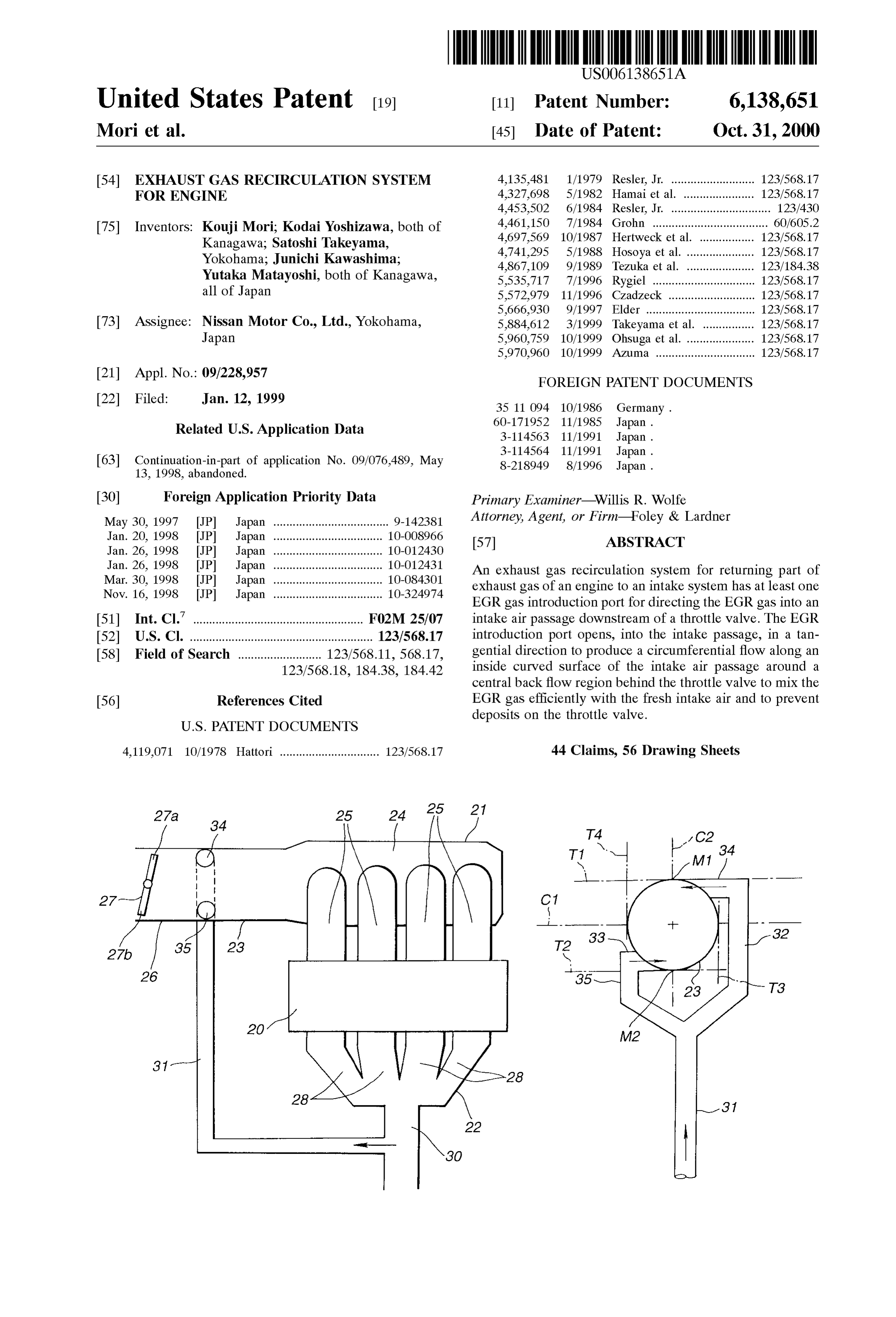
EXHAUST GAS RECIRCULATION SYSTEM Stream intake passage Section on a downstream Side of the FOR ENGINE throttle valve. The EGR introduction opening is opened in a predetermined EGR introducing direction to direct an inflow
RELATED APPLICATION EGR gas Stream circumferentially along a curved inside wall This application is a continuation-in-part of U.S. Ser. No. Surface of the downstream passage Section around a central 09/076,489 filed on May 13, 1998, now abandoned. region of the downstream intake passage Section. The intake System may comprise a pipe arrangement or pipe System and
BACKGROUND OF THE INVENTION a throttle Valve. The pipe arrangement is a single member or an assembly (Such as an assembly of an intake manifold and
The present invention relates to an exhaust gas recircu a throttle body) for defining passages for distributing intake lation (EGR) system for returning part of exhaust gas of an air to cylinders of the engine. The pipe arrangement com engine to an intake System to improve the fuel efficiency and prises a collector Section, a plurality of branches leading exhaust performance. from the collector Section, respectively, to the cylinders of In order to improve fuel consumption for less CO and to the engine, and a Section defining an intake passage for lower the combustion temperature for less NOx in compli 15 introducing the intake air into the collector Section. The ance with growing environmental concerns, there have been throttle valve is disposed in the intake passage at an inter proposed a variety of EGR Systems for recirculating a mediate position So that the intake passage is divided into an controlled amount of exhaust gas to the intake System in a upstream intake passage Section on an upstream Side of the normal operation not requiring higher output power. throttle Valve and the downstream intake passage Section Japanese Utility Model Kokai Publication No. 3(1991)- extending from the throttle Valve to the collector Section. 114563 shows a first conventional EGR system having a The EGR system is arranged to return part of the exhaust horizontally confronting pair of openings for introducing gas as EGR gas from the exhaust System into the down EGR gas into an intake pipe. Japanese Utility Model Kokai Stream passage Section of the intake System. The EGR Publication No. 3(1991)-114564 shows a second conven 25 System may comprise at least one EGR gas introduction port tional EGR System having an annular EGR gas passage having an EGR gas introduction opening for directing an around an intake pipe and a plurality of holes for introducing inflow EGR gas Stream into the downstream passage Sec the EGR gas from the annular passage into the intake pipe. tion. The EGR gas introduction opening is located down Both Systems are aimed to reduce the cylinder to cylinder stream of a first free end of the throttle valve in a closed nonuniformity in the EGR rate. position. The EGR gas introduction port extends along a Japanese Patent Kokai Publication No. 8(1996)-218949 tangential direction tangential to a curved inside wall Surface discloses a third conventional EGR system having an EGR of the downstream passage SubSection. An inflow direction passage opening to a Second Surge tank provided down of the EGR gas introduction port may be parallel to a croSS Stream of a first Surge tank in an intake passage. This system Sectional plane of the downstream intake passage Section or introduces the EGR gas at a remote position from a throttle may be inclined downstream So as to form a predetermined valve, to prevent adhesion to the throttle valve, of harmful 35 angle with respect to a direction of a fresh intake air Stream components (deposits) of the exhaust gas mixture. in the downstream intake passage SubSection. Japanese Utility Model Kokai Publication No. 60-171952 The EGR port is thus directed to produce a screw-like discloses a fourth conventional EGR system having an EGR Spiral flow advancing downstream along the inside Surface pipe connected, through an EGR valve, to a Surge tank of an 40 of the intake passage SubSection. An intake air Stream is intake manifold. induced into the spiral flow and well mixed with the EGR gas. The Spiral flow promotes mixing of the EGR gas with
SUMMARY OF THE INVENTION the intake air, and prevents deposits by keeping the EGR gas However, the conventional EGR systems are not com outside a central back flow region behind the throttle valve. pletely sufficient for mixing the EGR gas with the intake air 45 BRIEF DESCRIPTION OF THE DRAWINGS and for uniformly distributing the EGR gas to the engine cylinders. In the Second System, conditions of fresh intake FIG. 1 is a Schematic view showing an engine System air Streams through the throttle Valve exert large influence on having EGR introduction ports according to a first embodi the mixing of the EGR gas and adhesion of deposits to the ment of the present invention.
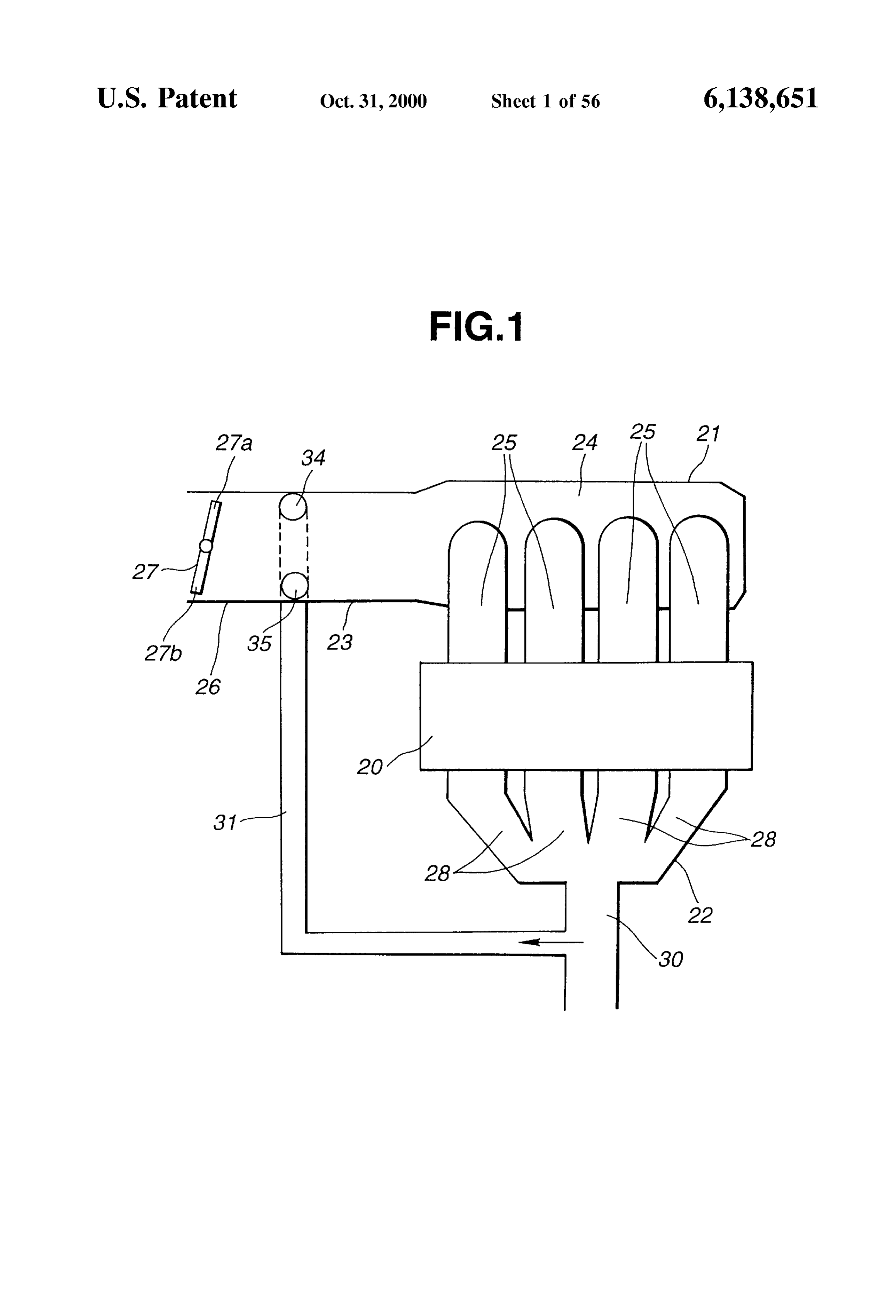
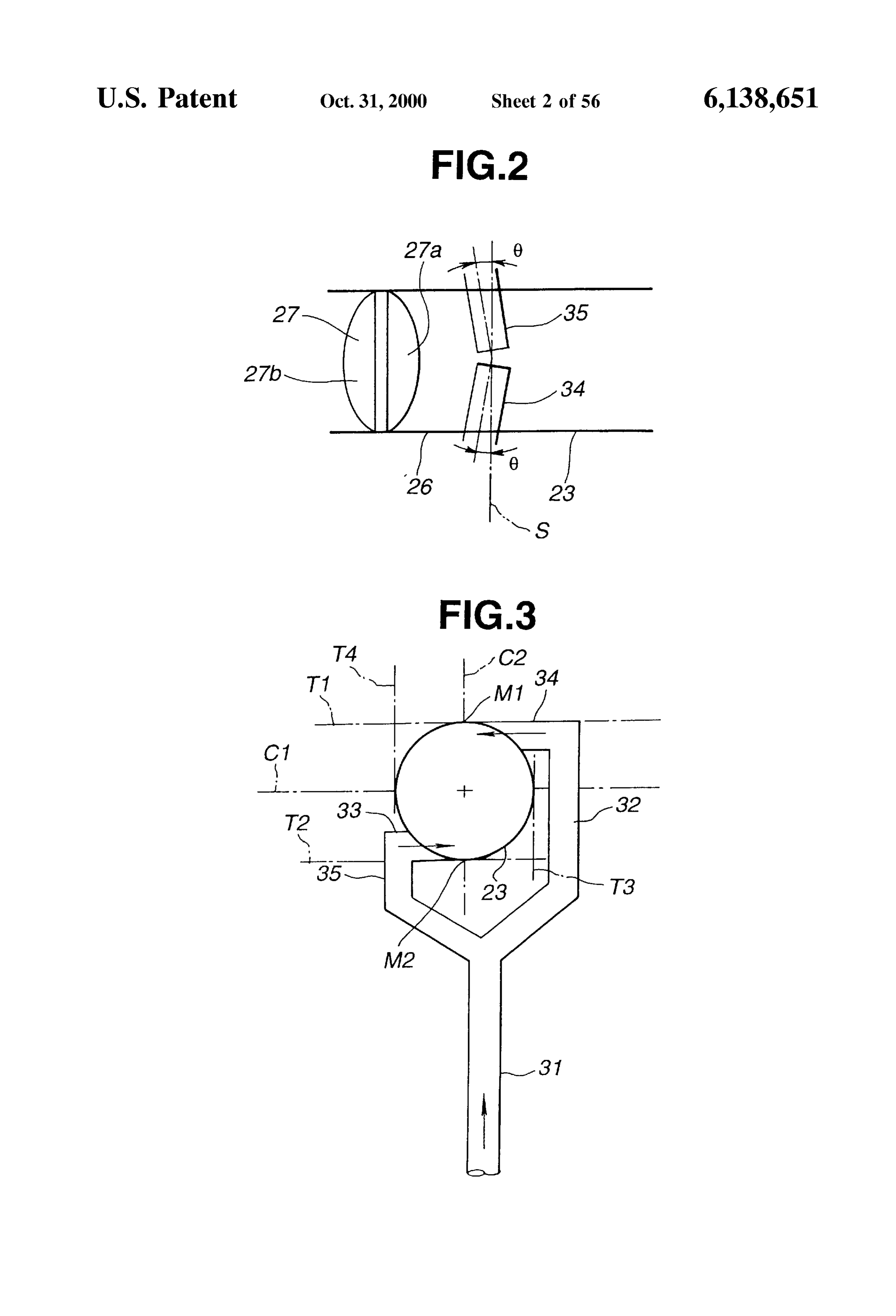
throttle valve. Insufficient blend of the EGR gas with the 50 FIG.2 is a view showing an arrangement of the EGR ports intake air is causative of uneven distribution of the EGR rate according to the first embodiment. among the cylinders, unstable engine performance, increase FIG. 3 is a view showing the arrangement of the EGR of emission and poor fuel economy. Deposits on a throttle ports according to the first embodiment. Valve may decrease the accuracy of intake air quantity FIG. 4 is a graph showing an EGR region. control, and may make the throttle valve immovable. In the 55
FIGS.
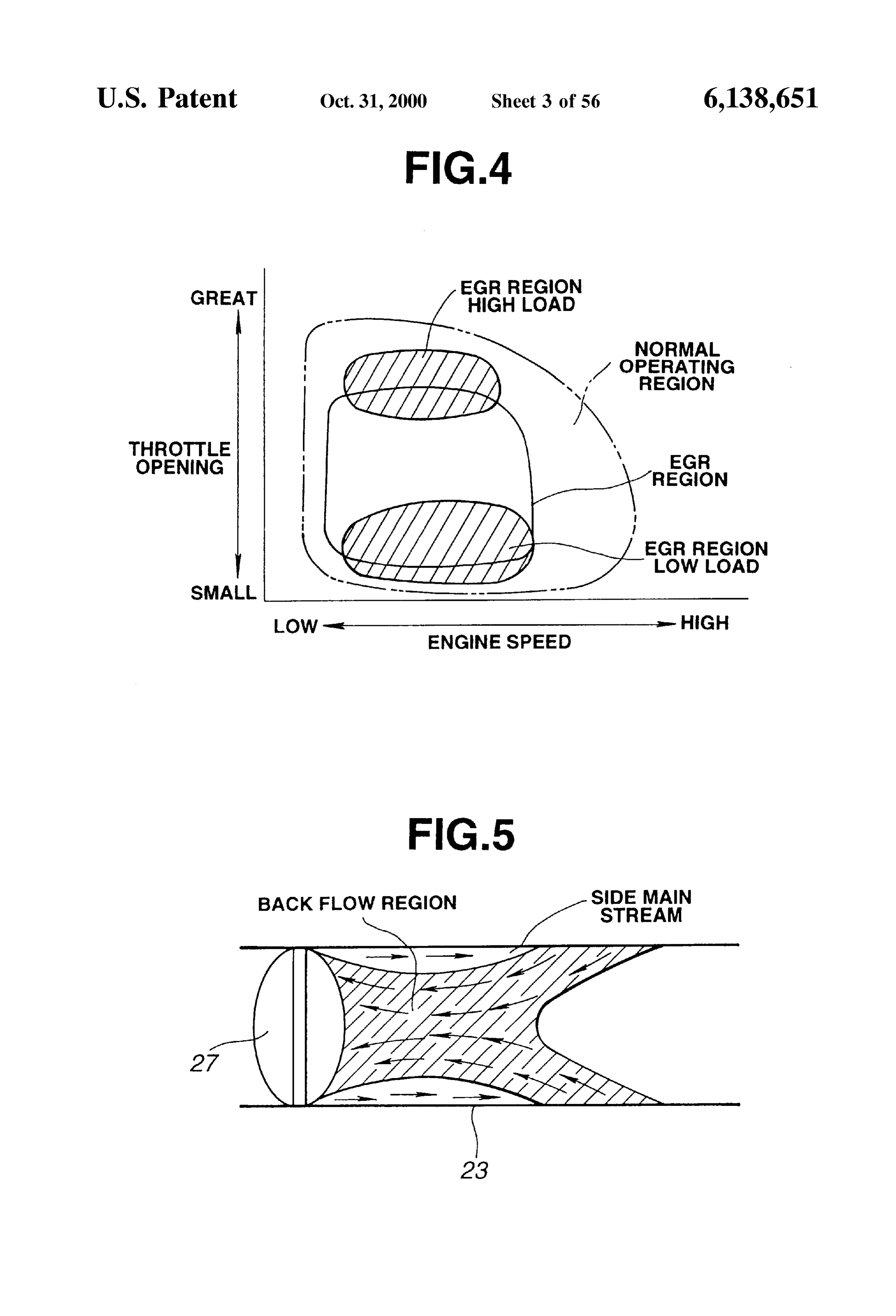
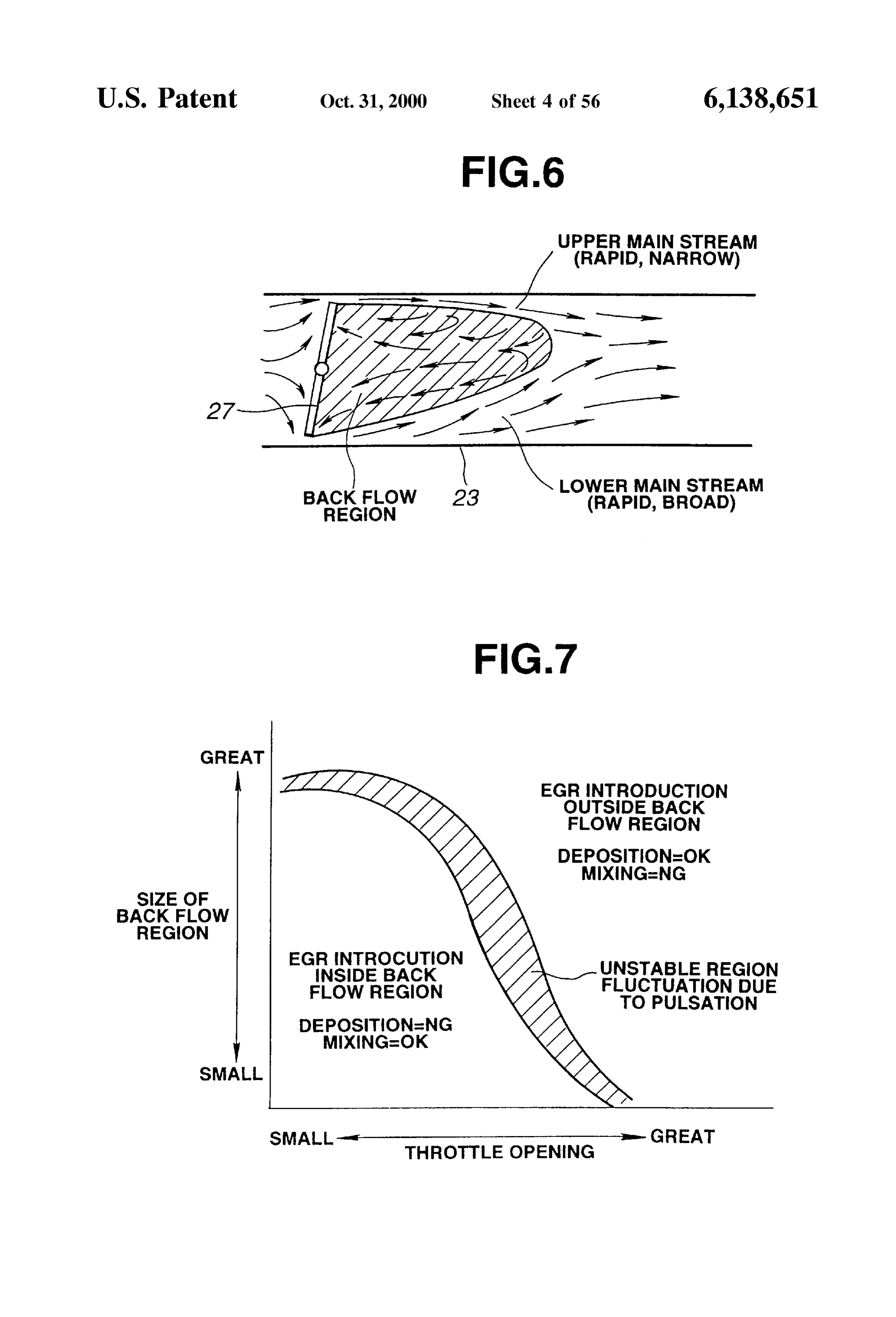
fourth example, the EGR gas is Swept downstream by a fresh downstream 5 and 6 are views for illustrating streams on the main intake Stream, and the EGR gas can hardly enter the side of a throttle valve. most upstream branch of the intake manifold. FIG. 7 is a graph showing a relation between a throttle It is therefore an object of the present invention to provide opening and a back flow region.
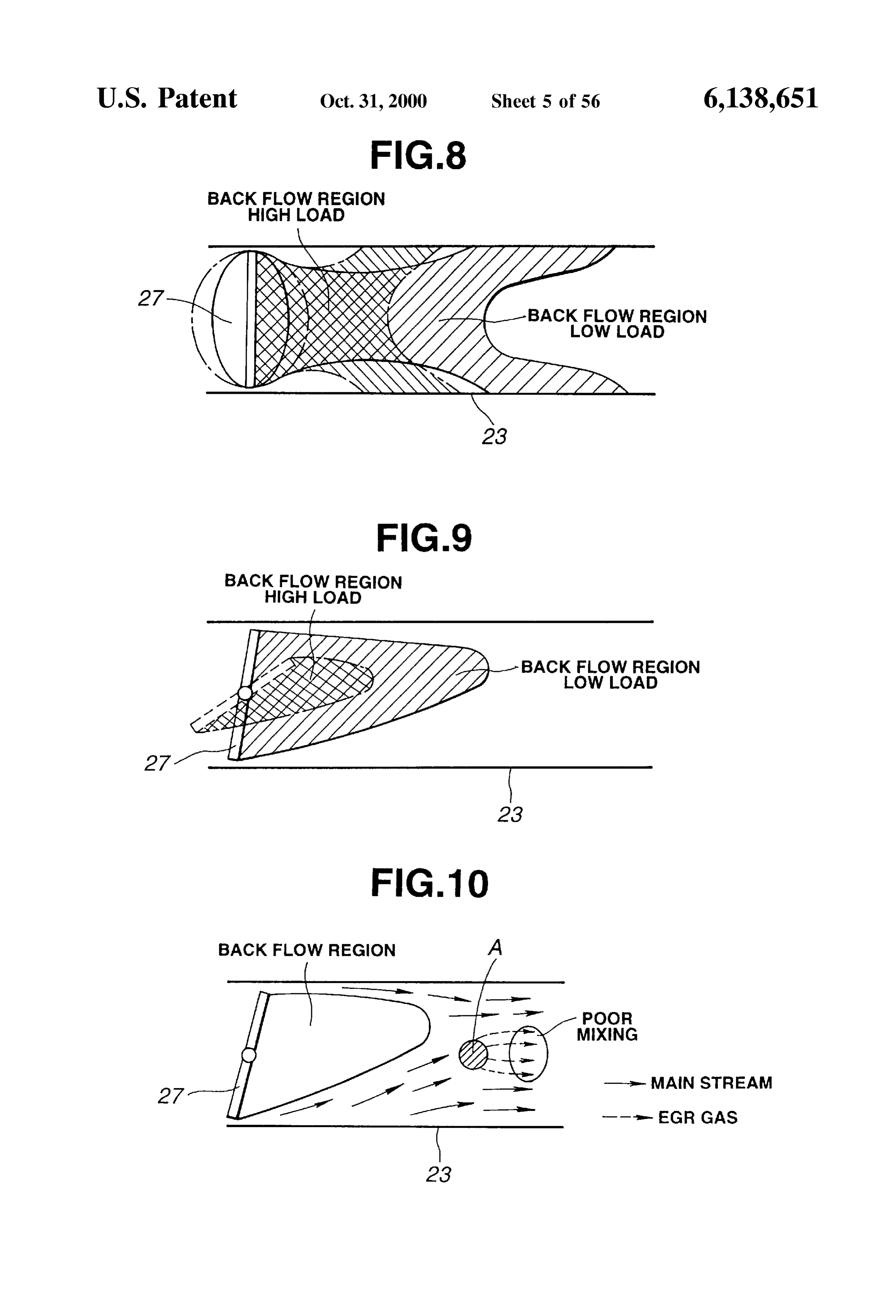
an exhaust gas recirculation type engine System for uni 60 FIGS. 8 and 9 are views for illustrating extents of a back formizing the EGR distribution and protect a throttle valve flow region under low load condition and high load condi against deposits. tion.
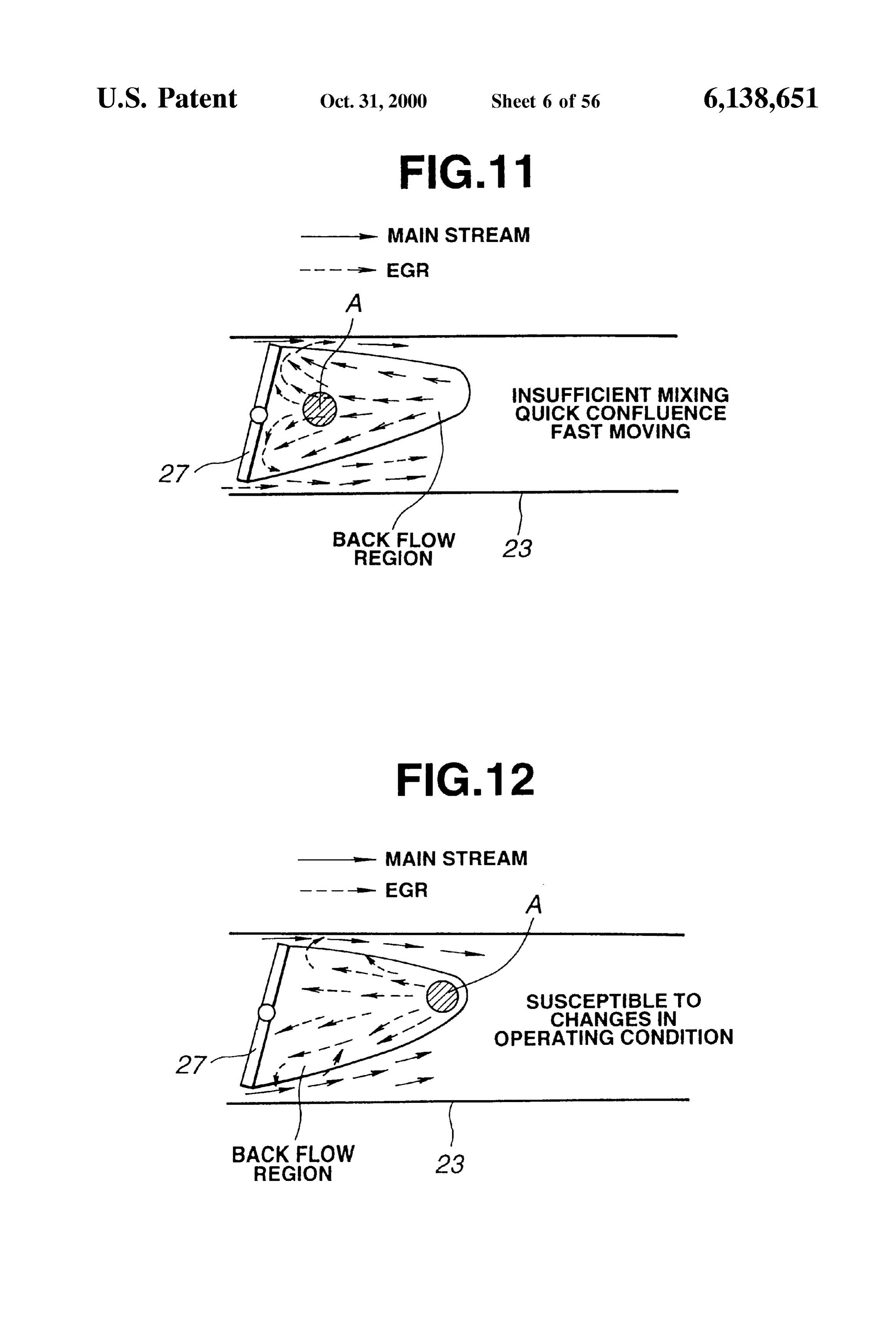
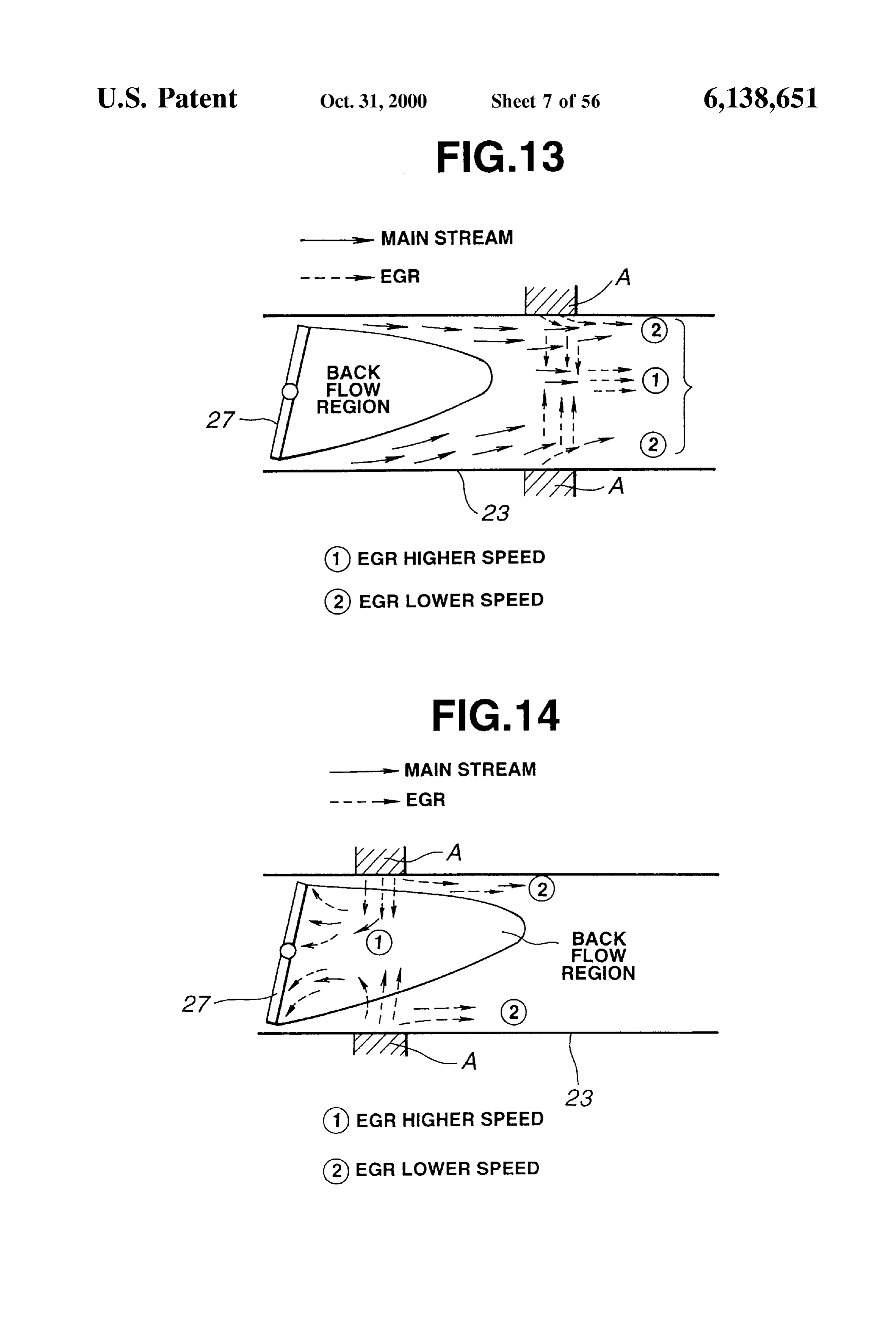
According to the present invention, an engine System FIGS. 10-14 are views for illustrating EGR gas diffusion comprises an engine, an exhaust System, an intake System from various introduction positions.
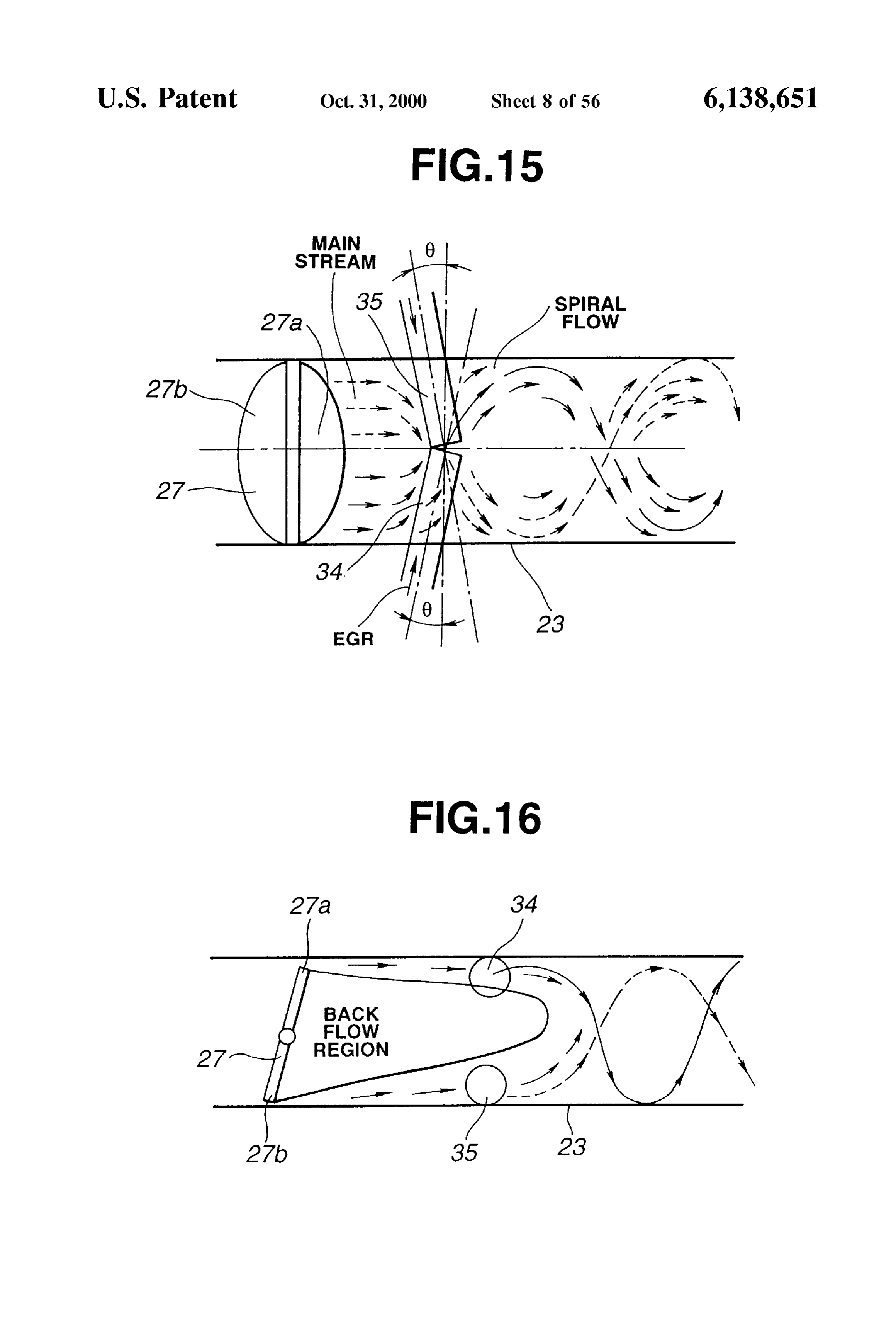
comprising a throttle Valve in an intake passage, and an EGR 65 FIGS. 15, 16 and 17 are views for illustrating a spiral flow system. The EGR system comprises at least one EGR produced by the EGR introduction ports according to the introduction opening for introducing EGR gas into a down first embodiment of the invention.
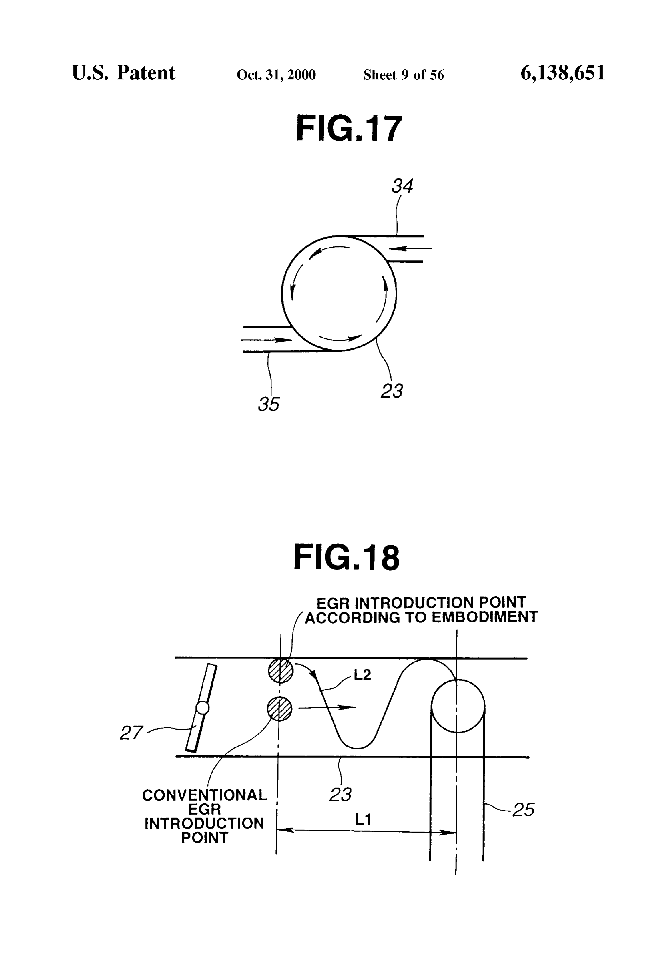
Page 59
FIG. 18 is a view showing a travel distance of the EGR ninth embodiment. (The term “vertical” means that the gas along a spiral path according to the first embodiment of Section is perpendicular to the Swing axis of the throttle the invention. valve.)
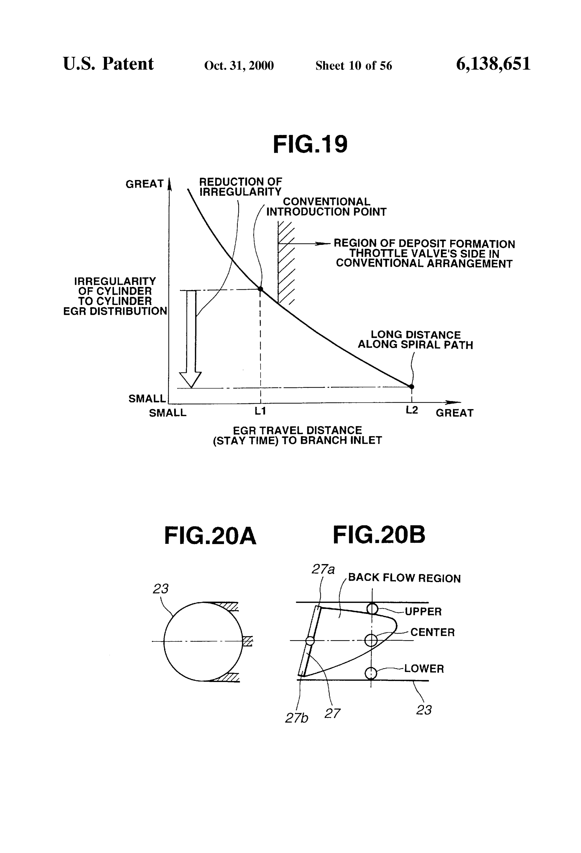
FIG. 19 is a graph for illustrating improvement in cylinder FIG. 42 is a Schematic croSS Sectional view showing the to cylinder EGR distribution by the spiral EGR path shown position and orientation of the EGR introduction opening of in FIG. 18. FIG. 41.
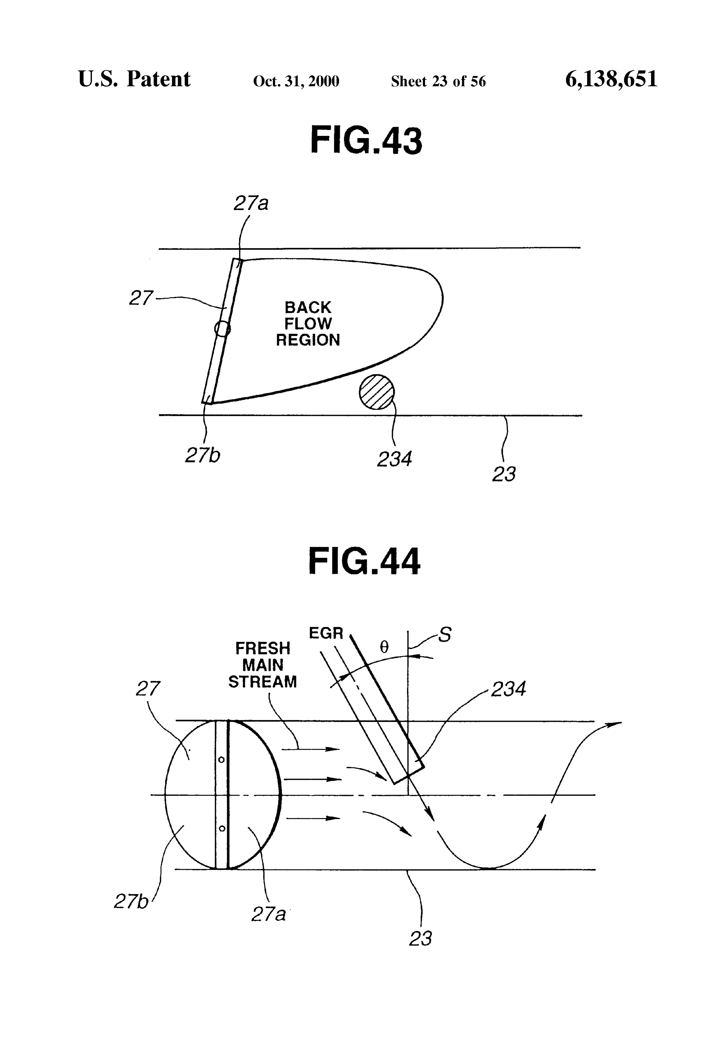
FIGS. 20A and 20B are schematic views for illustrating FIG. 43 is a schematic vertical longitudinal sectional view the EGR introductions positions according to the first showing an EGR introduction opening according to a tenth embodiment.
embodiment.
FIG. 21 is a graph for illustrating improvement in deposit FIG. 44 is a Schematic horizontal longitudinal Sectional view showing the EGR introduction opening of FIG. 43.
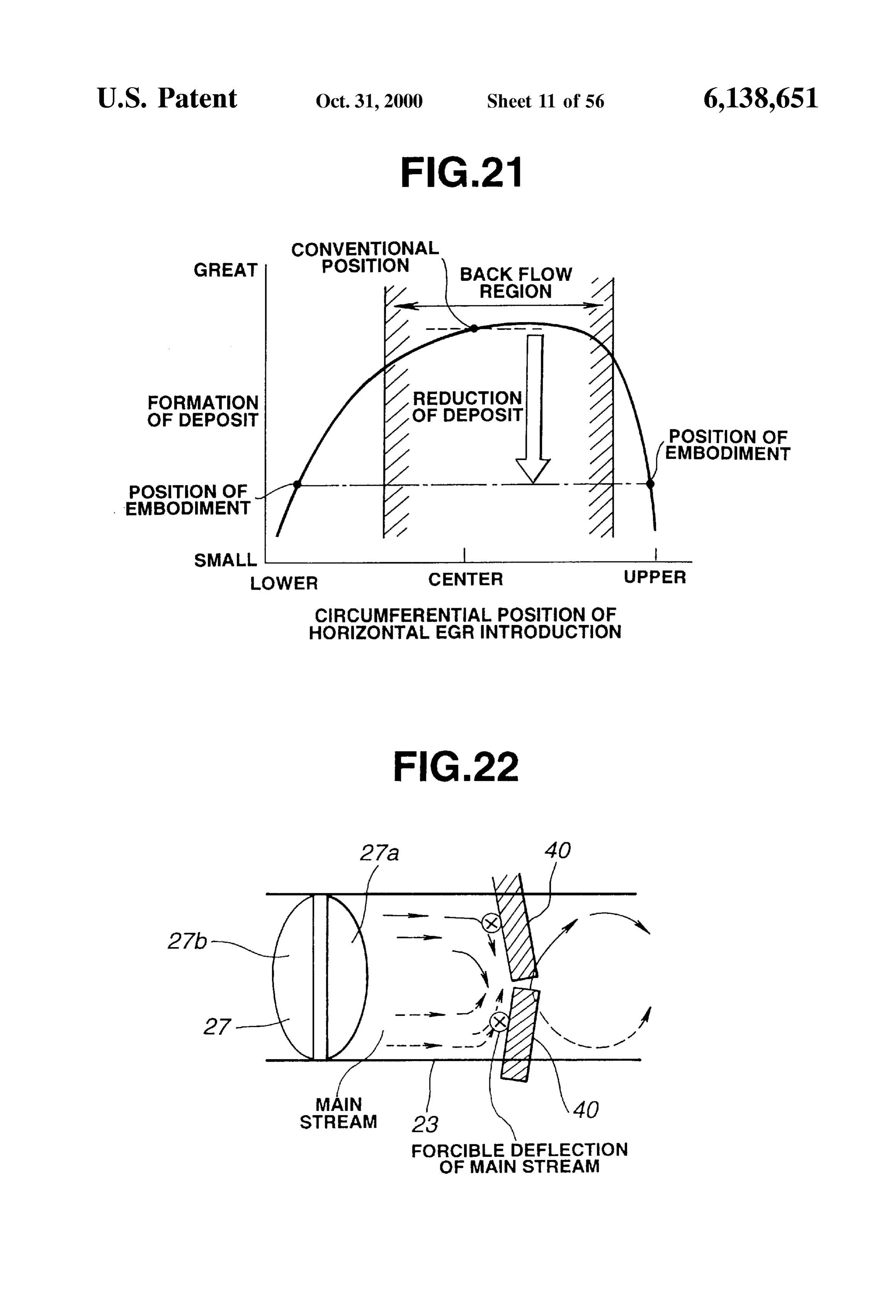
prevention by the EGR introduction positions according to FIG. 45 is a schematic horizontal longitudinal sectional the first embodiment.
View showing an EGR introduction opening according to an
FIG. 22 is a Schematic view showing gas introduction eleventh embodiment.
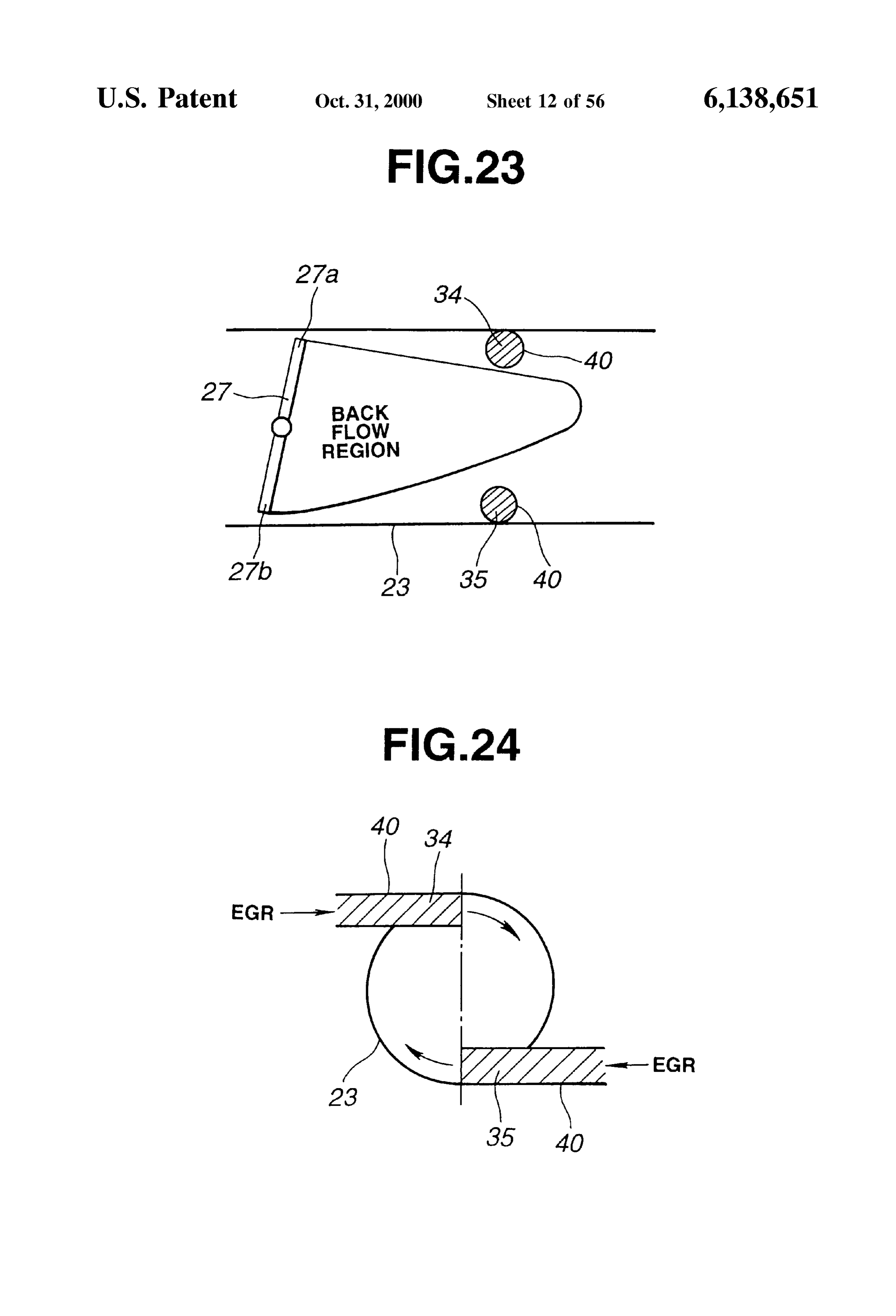
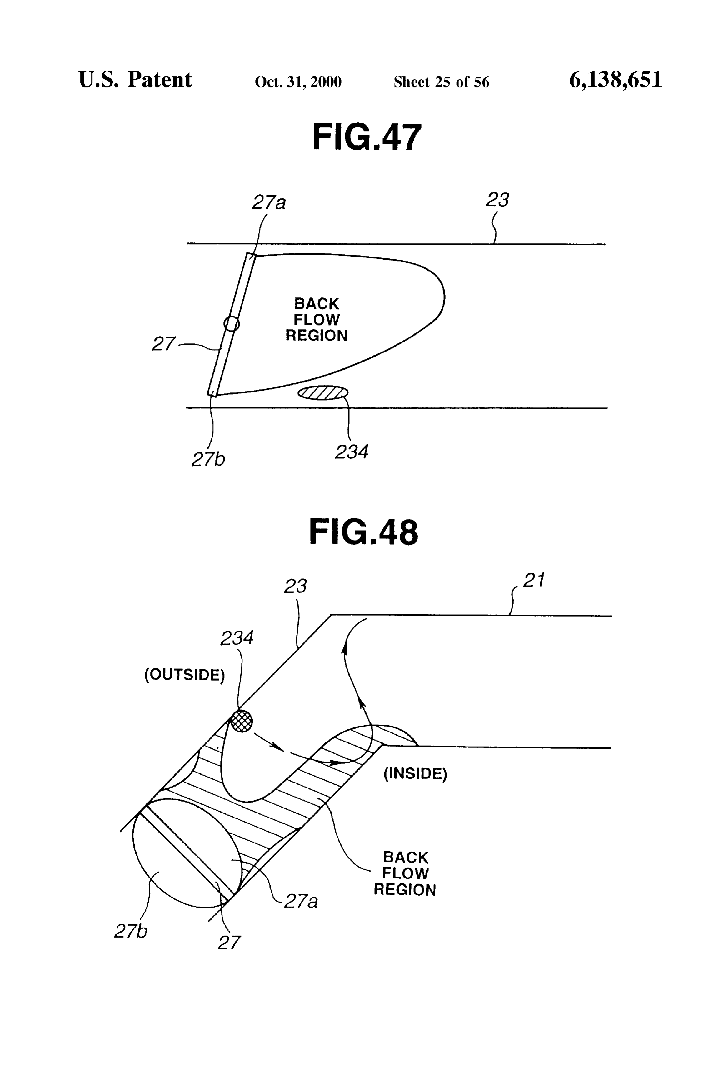
ports of an EGR System according to a Second embodiment 15 FIG. 46 is a schematic cross sectional view showing the of the present invention. EGR introduction opening of FIG. 45. FIG. 23 is a Schematic view showing the arrangement of FIG. 47 is a schematic vertical longitudinal sectional view the introduction ports according to the Second embodiment. showing an EGR introduction opening according to a FIG. 24 is a Schematic view showing the arrangement of twelfth embodiment.
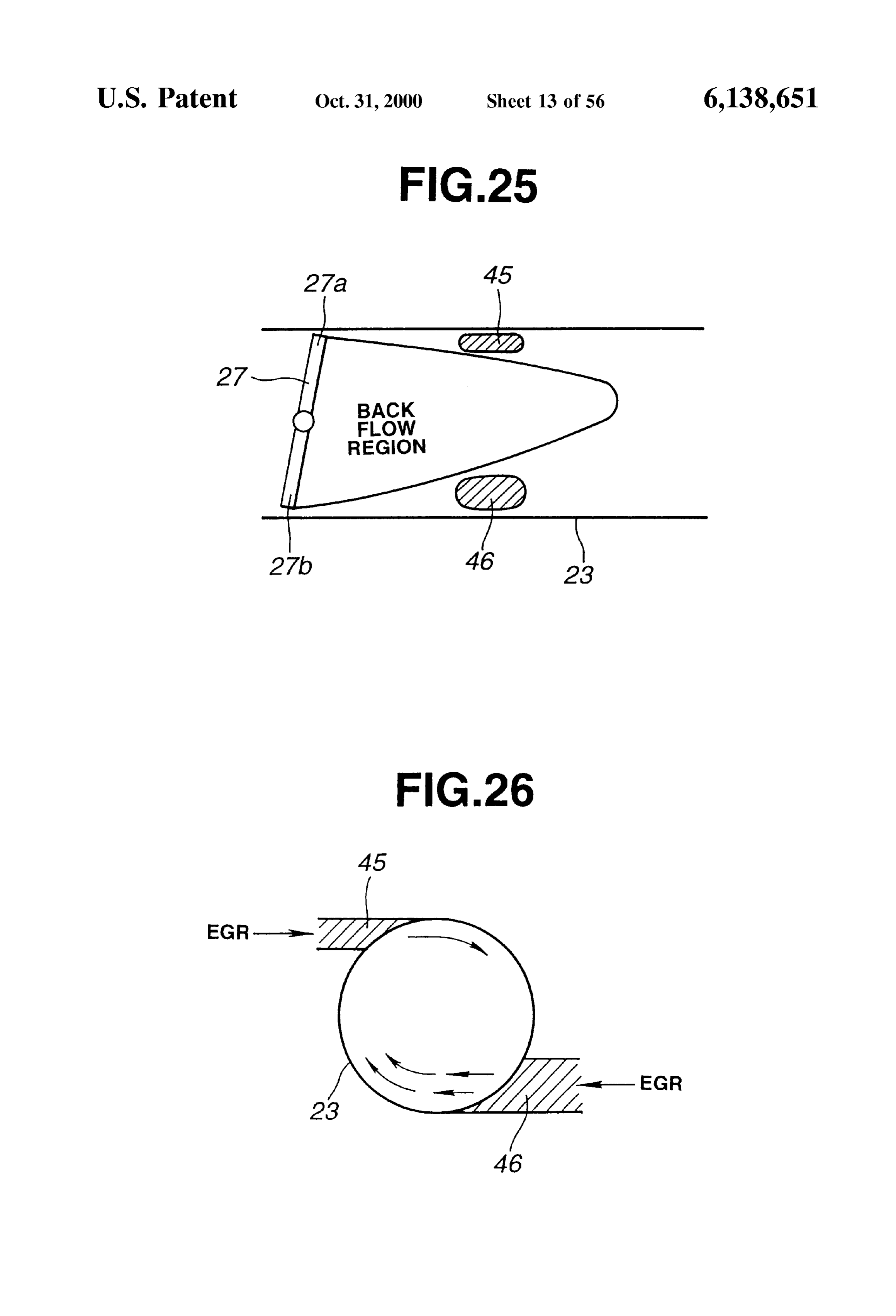
the introduction ports according to the Second embodiment. FIG. 48 is a schematic horizontal longitudinal sectional FIG. 25 is a Schematic view showing gas introduction View showing an EGR introduction opening according to a ports of an EGR System according to a third embodiment of thirteenth embodiment.
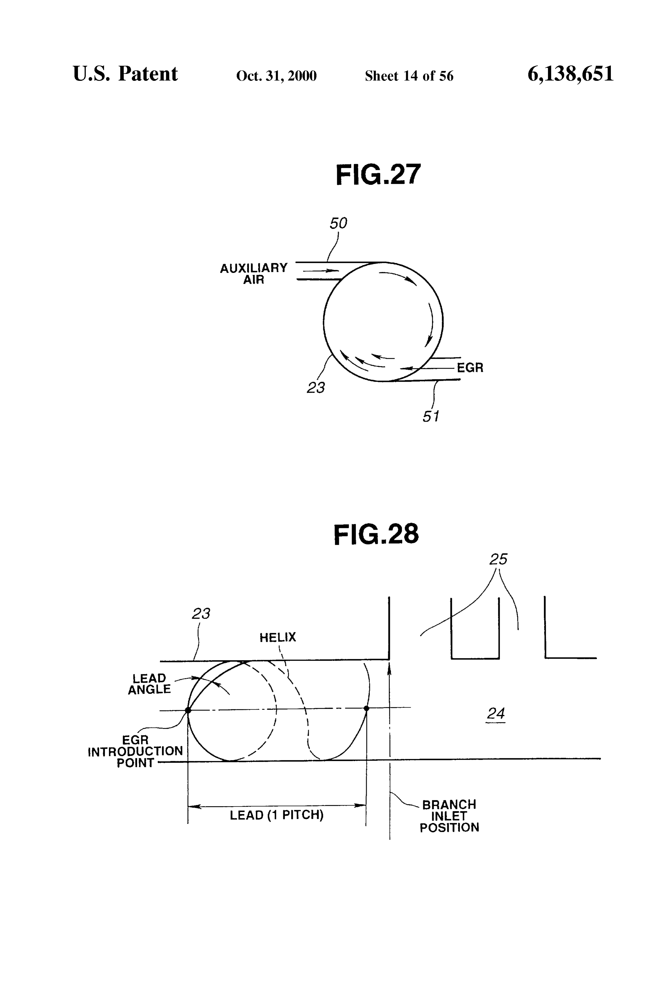
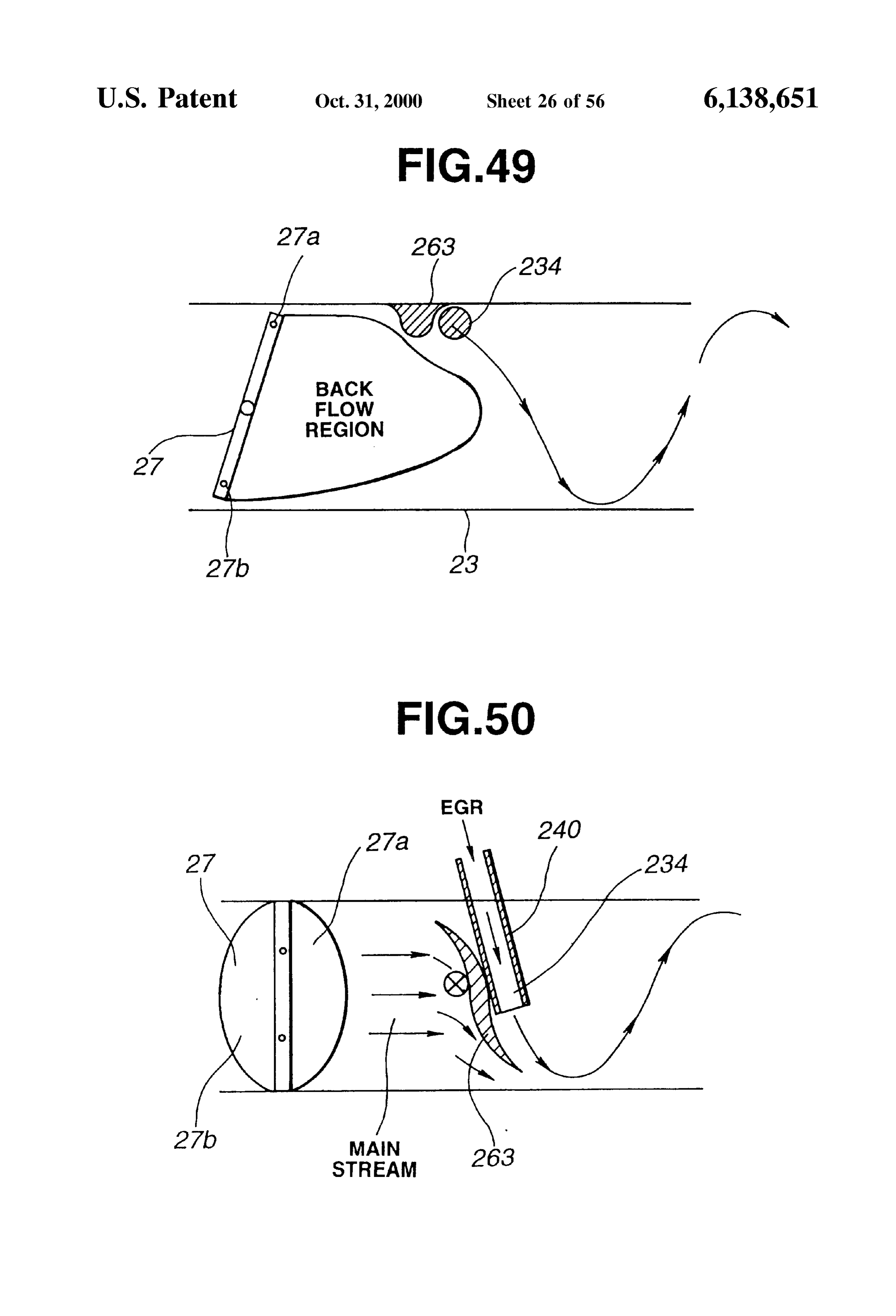
the present invention. FIG. 49 is a schematic vertical longitudinal sectional view FIG. 26 is a Schematic view showing the arrangement of 25 showing an EGR introduction opening and a deflecting rib the introduction ports according to the third embodiment. according to a fourteenth embodiment. FIG. 27 is a Schematic view showing gas introduction FIG. 50 is a schematic horizontal longitudinal sectional ports of an EGR System according to a fourth embodiment View showing the EGR introduction opening and deflecting rib of FIG. 49.
of the present invention.
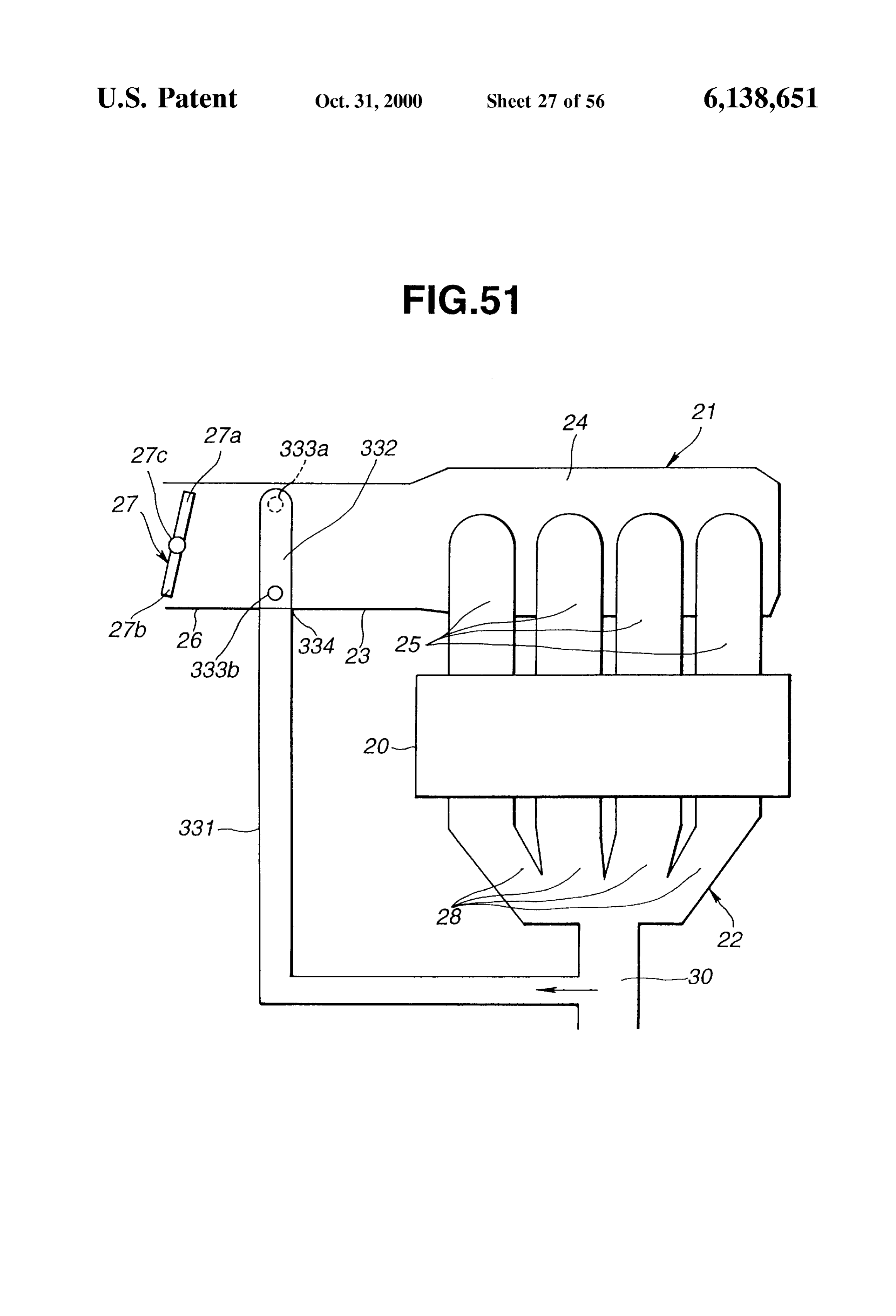
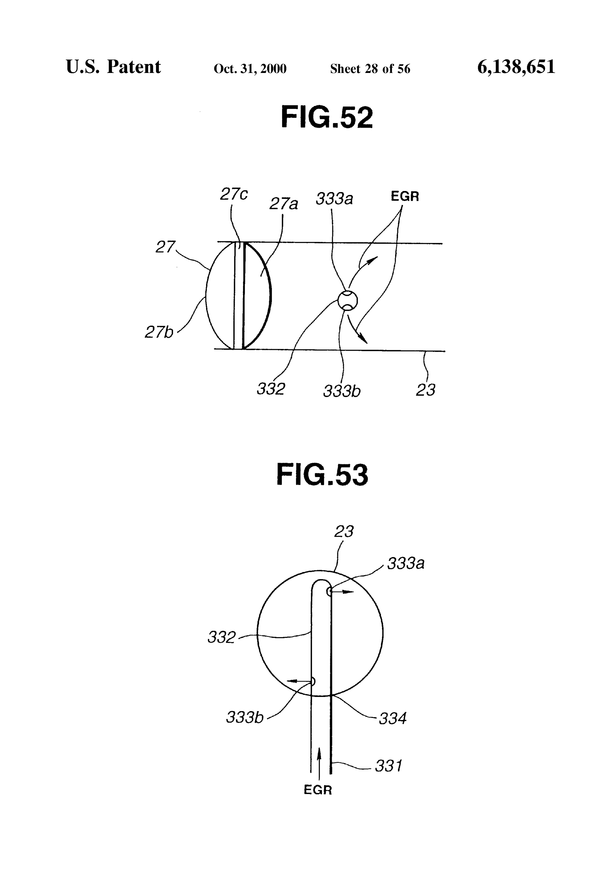
FIG. 28 is a schematic view showing an EGR introduction FIG. 51 is a Schematic view showing an engine System point according to a fifth embodiment of the present inven according to a fifteenth embodiment.
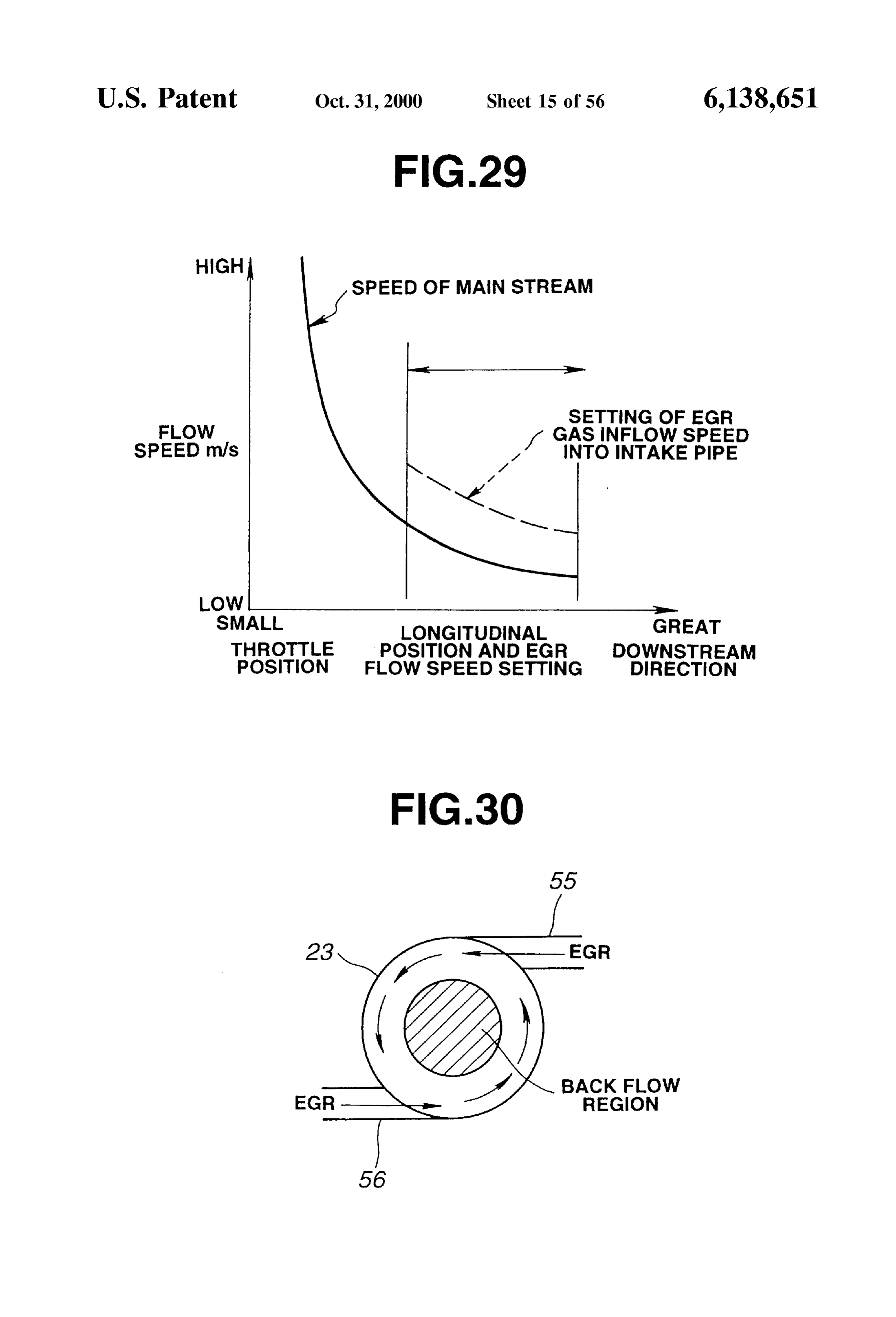
tion. FIG. 52 is a schematic longitudinal sectional view show FIG. 29 is a graph showing factors to determine gas ing EGR introduction openings of FIG. 51. introduction ports of an EGR System according to a sixth FIG. 53 is a schematic cross sectional view showing the embodiment of the present invention. 35 EGR introduction openings of FIG. 51.
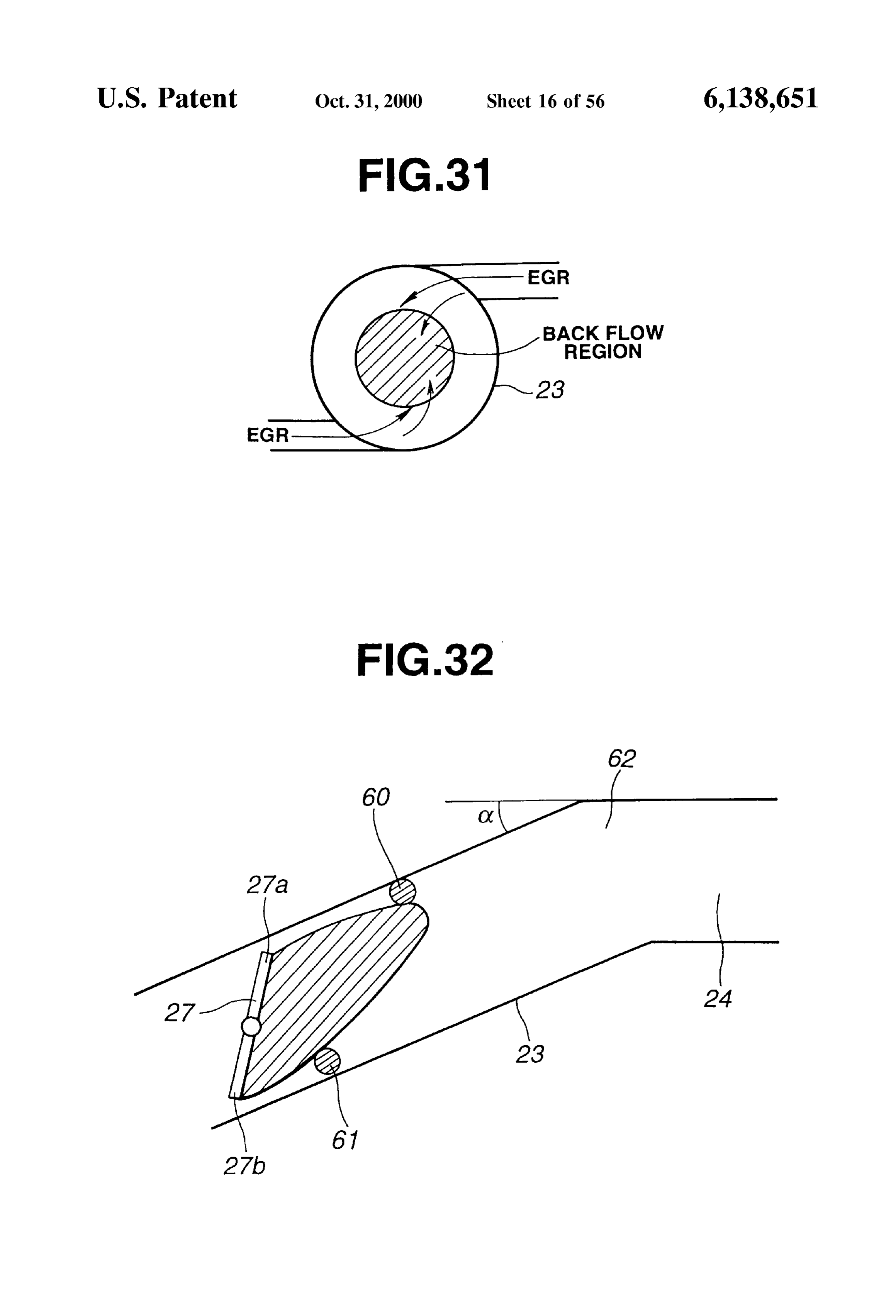
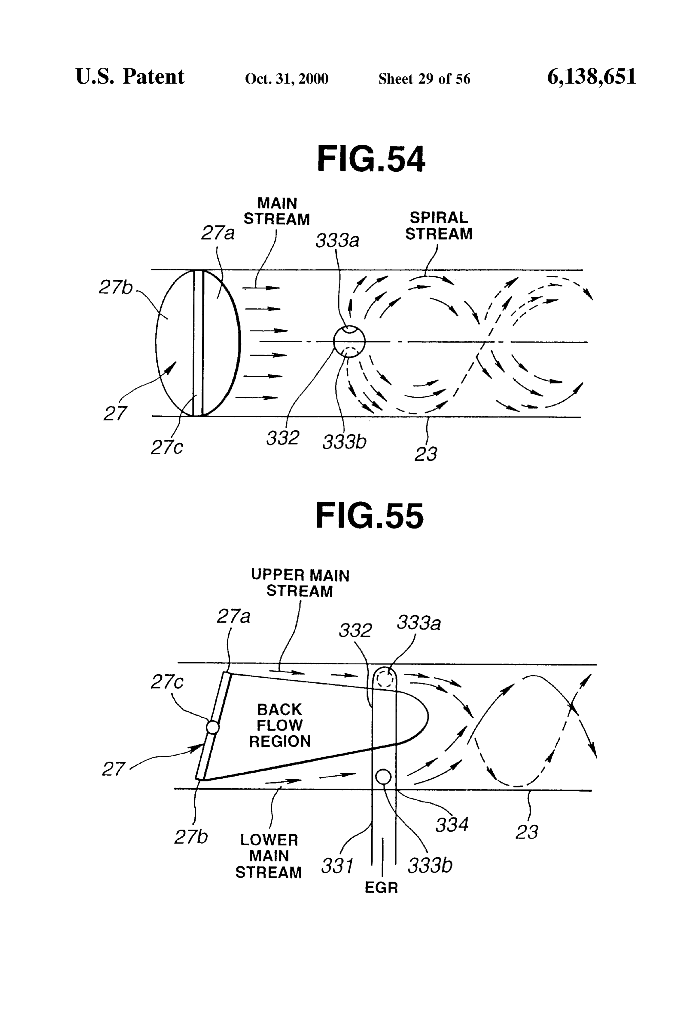
FIGS. 30 and 31 are views for illustrating effect of the gas view FIG. 54 is a schematic horizontal longitudinal sectional introduction ports according to the Sixth embodiment. for illustrating EGR streams produced by the EGR introduction openings of FIG. 51.
FIG.32 is a schematic view showing introduction ports of an EGR System according to a Seventh embodiment of the 40 forFIG.55 is a schematic vertical longitudinal sectional view illustrating EGR streams produced by the EGR intro present invention. duction openings of FIG. 51.
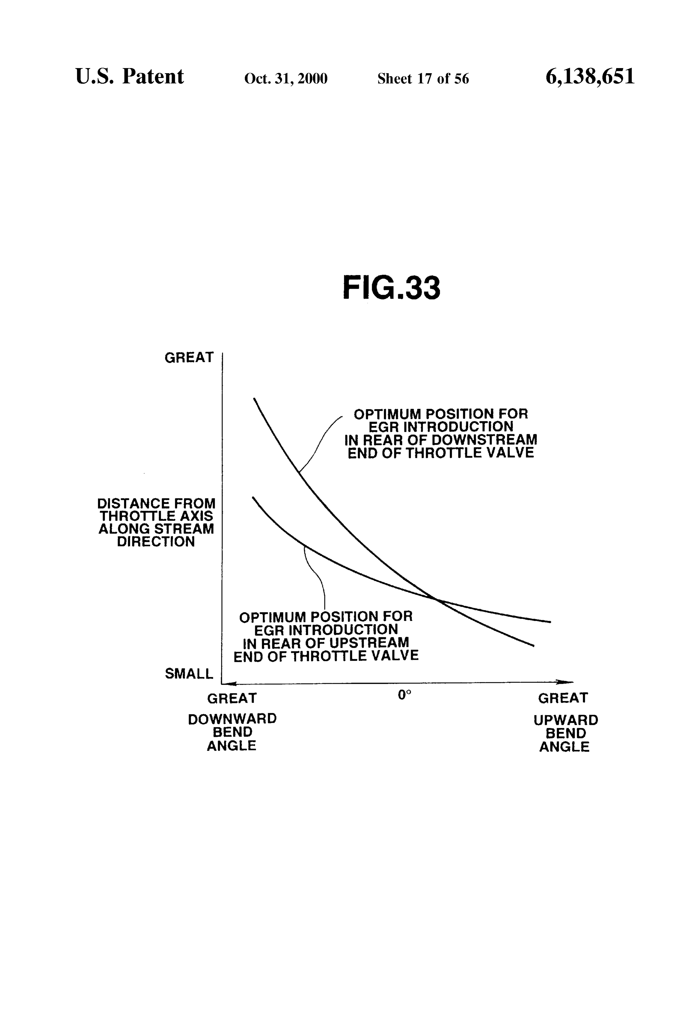
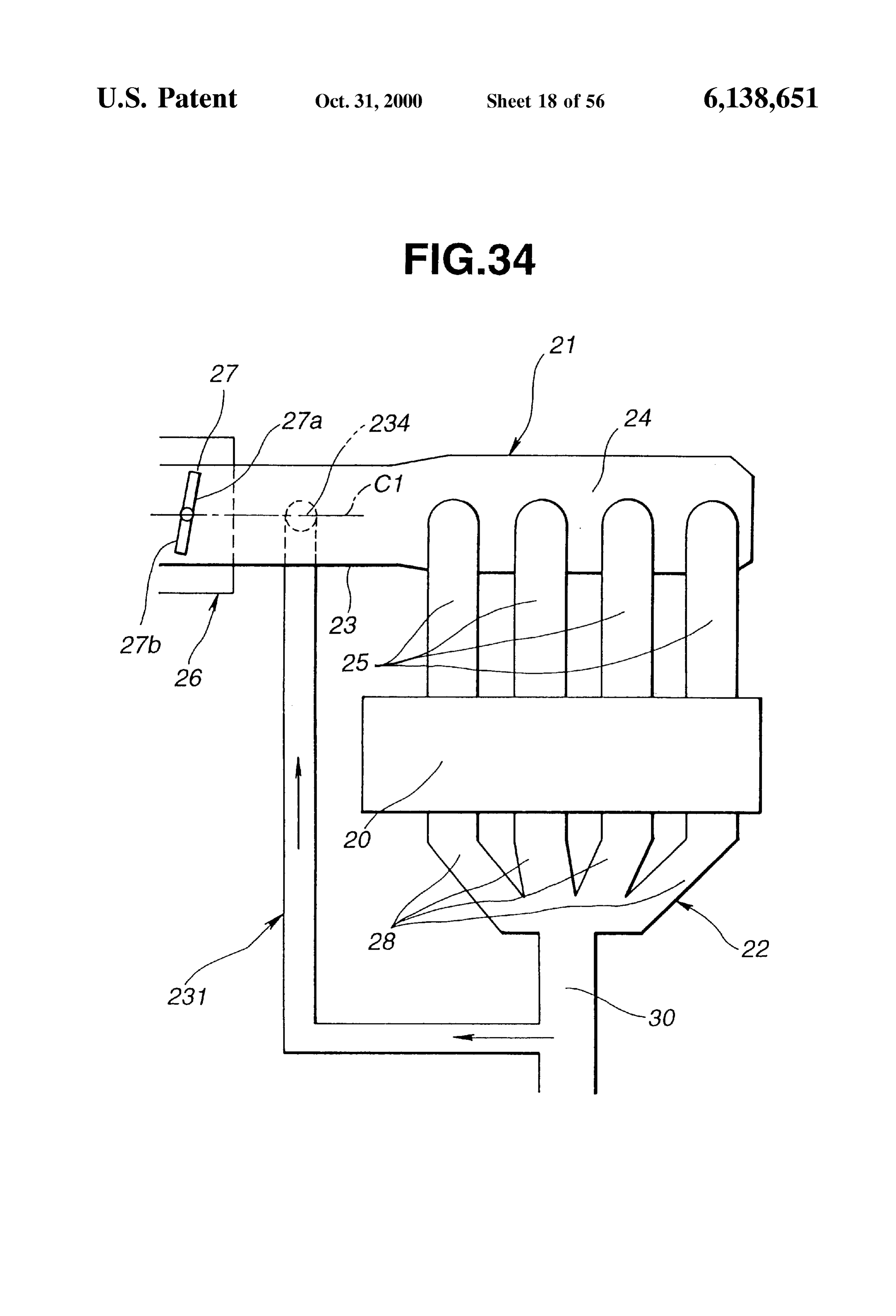
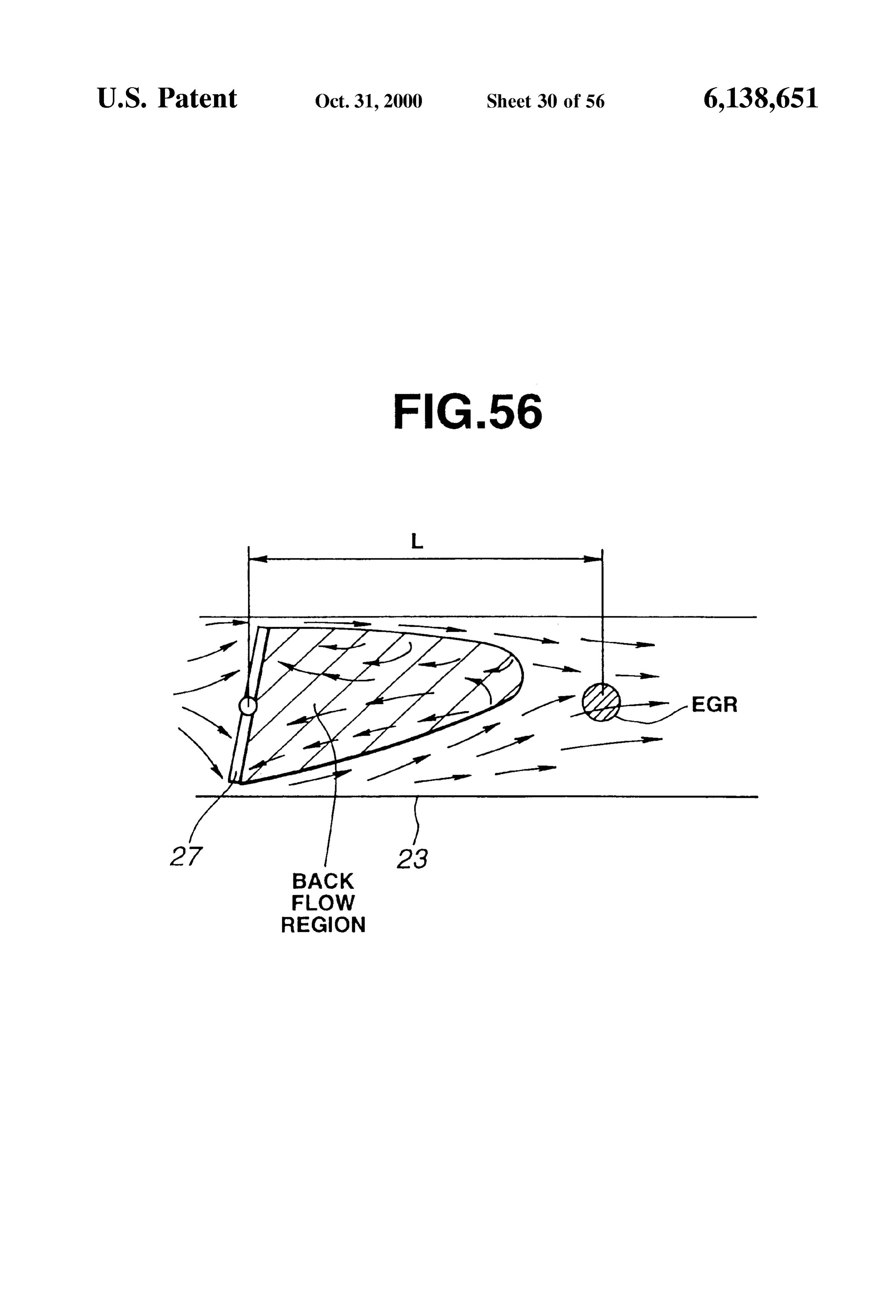
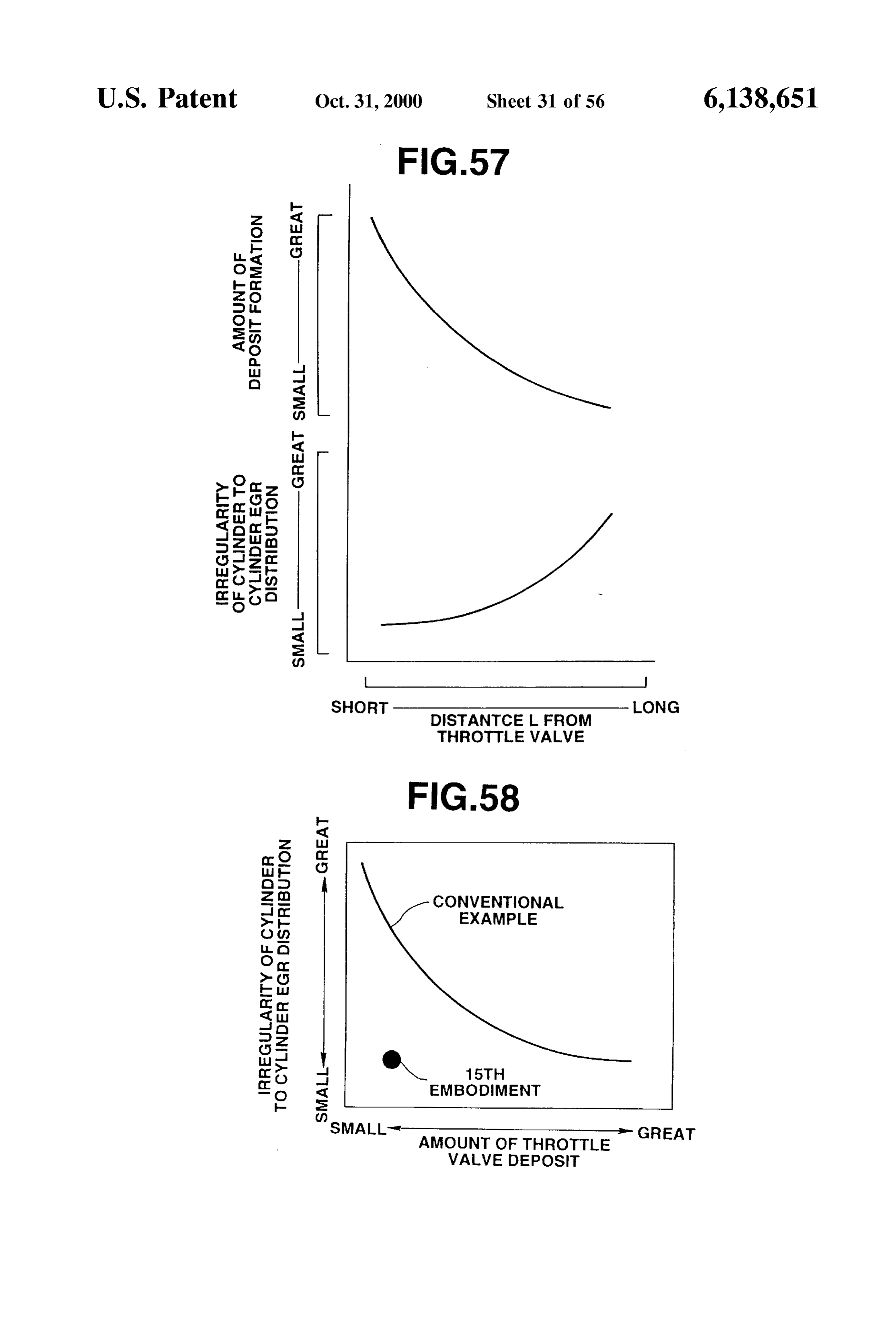
FIG.33 is a graph for illustrating EGR introduction points FIG. 56 is a schematic vertical longitudinal sectional view according to the Seventh embodiment. showing a back flow region formed behind the throttle valve. FIG. 34 is a Schematic view showing an engine System FIG. 57 is a graph showing dependence of EGR distri according to an eighth embodiment. 45 bution and deposit formation on a distance of an EGR FIG. 35 is a view showing an arrangement of an EGR introduction point from the throttle valve.
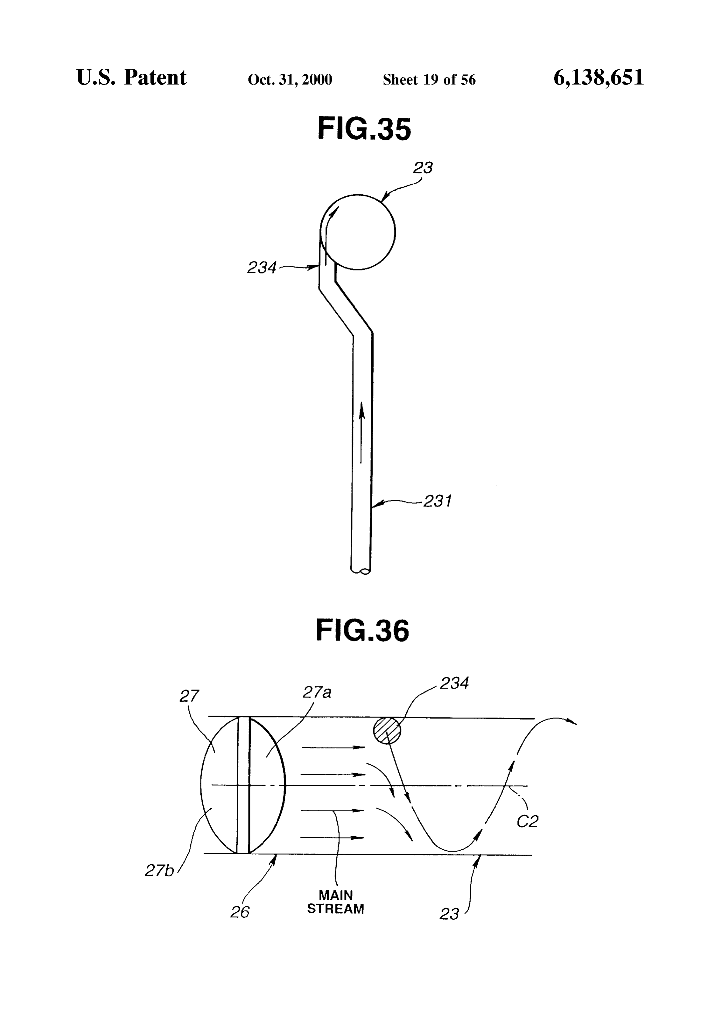
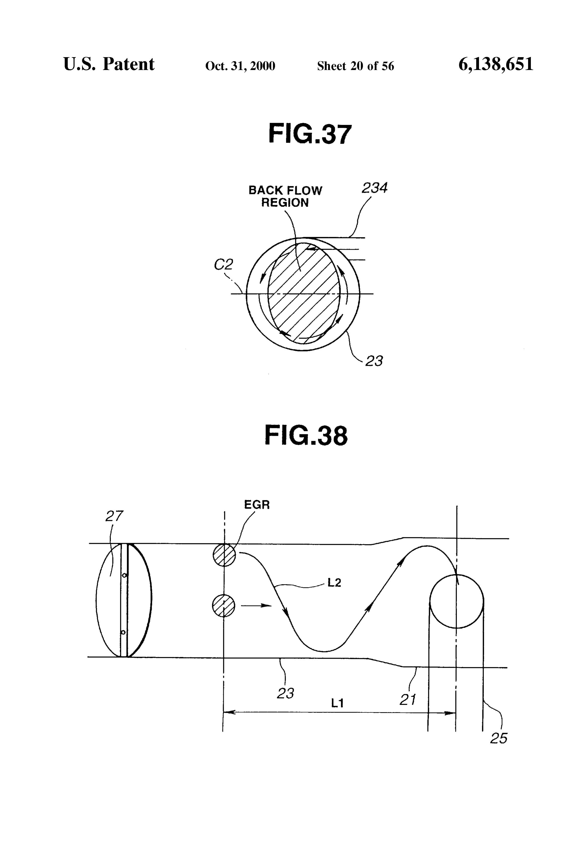
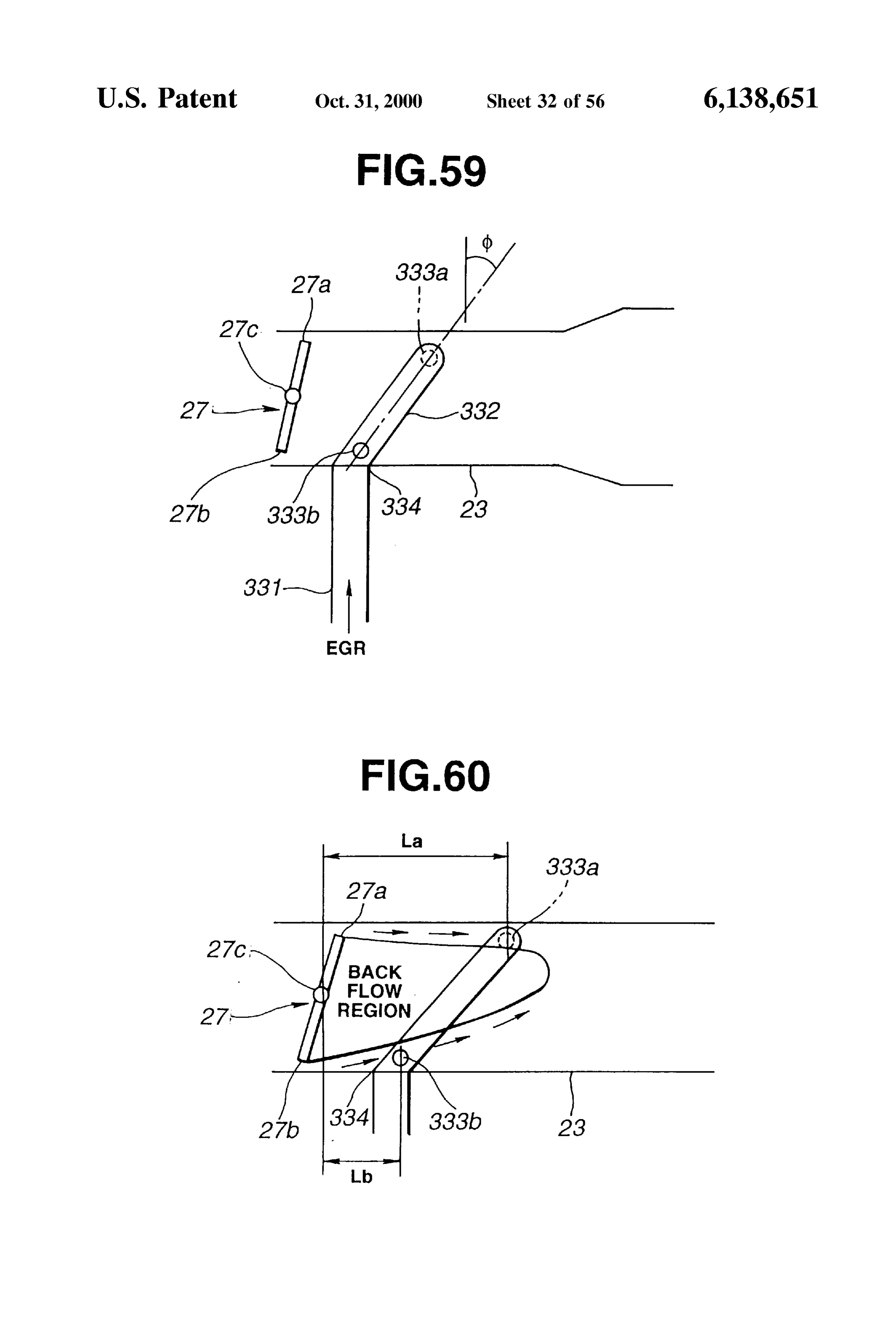
introduction opening of the engine System of FIG. 34. FIG. 58 is a graph showing effect of the fifteenth embodi FIG. 36 is a schematic longitudinal sectional view for ment on the EGR distribution and deposit formation. illustrating an EGR stream from the EGR introduction 50 FIG. 59 is a schematic vertical longitudinal sectional view opening of FIG. 35. showing EGR introduction openings according to a six FIG.37 is a schematic cross sectional view for illustrating teenth embodiment.
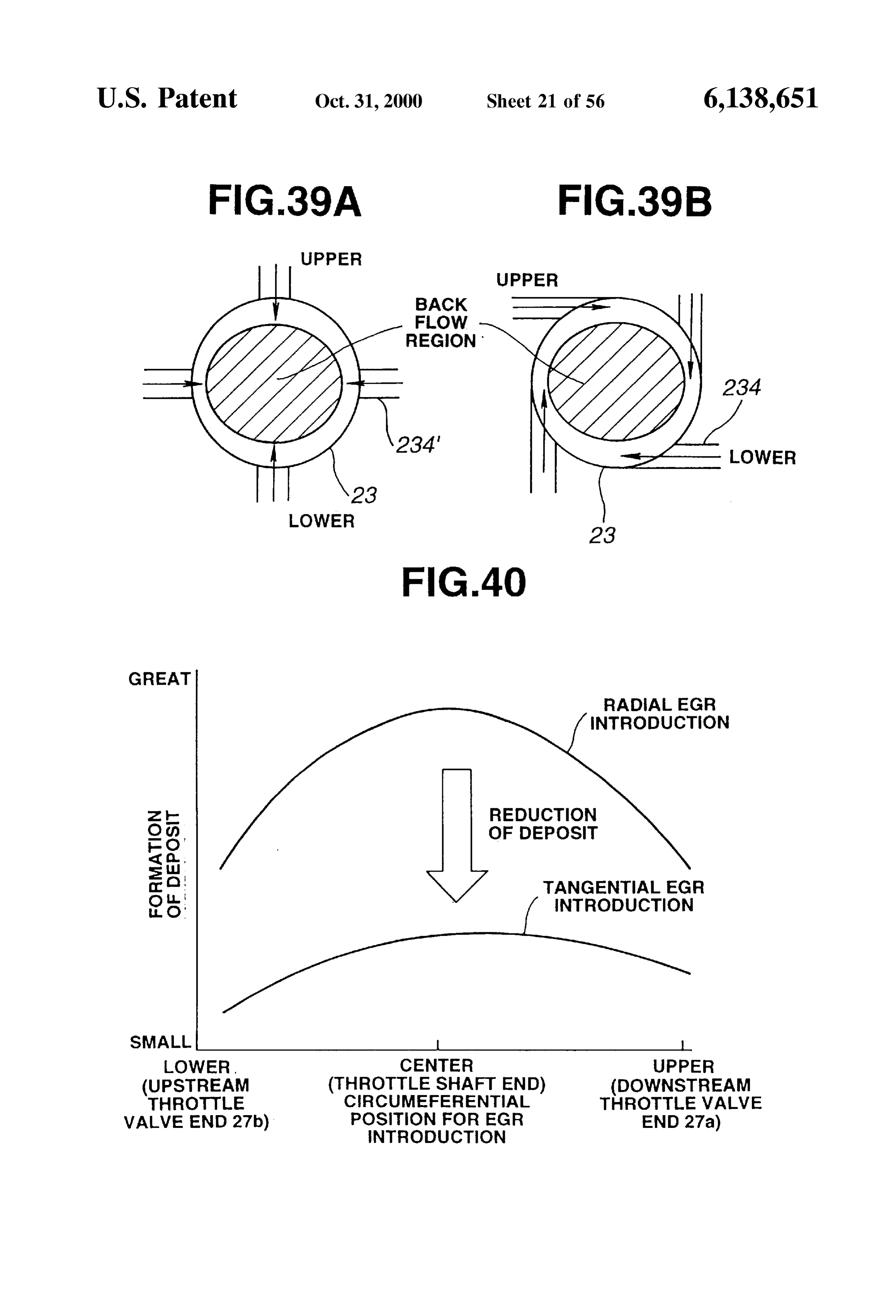
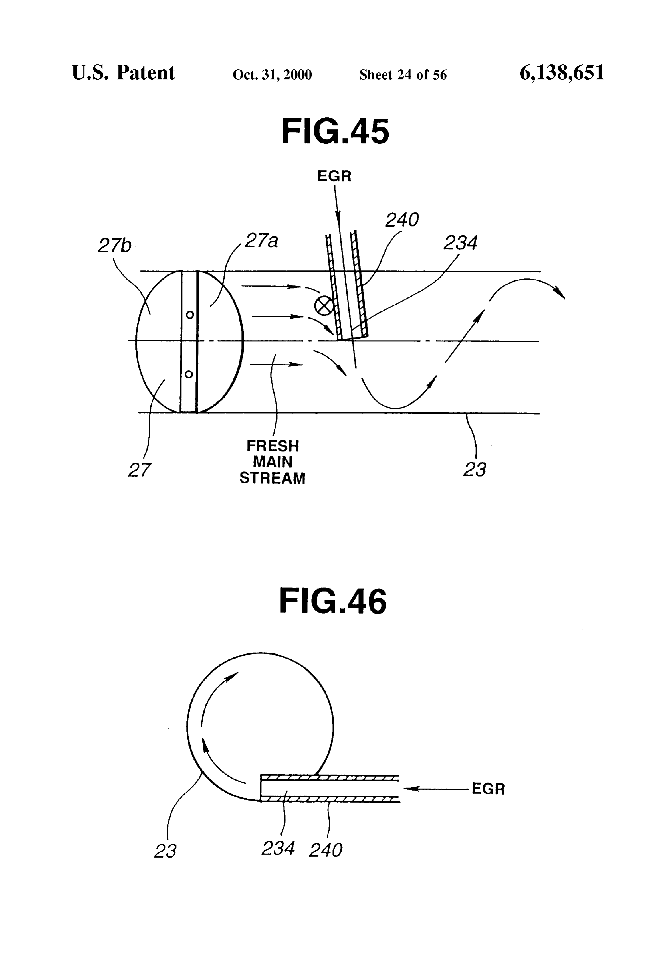
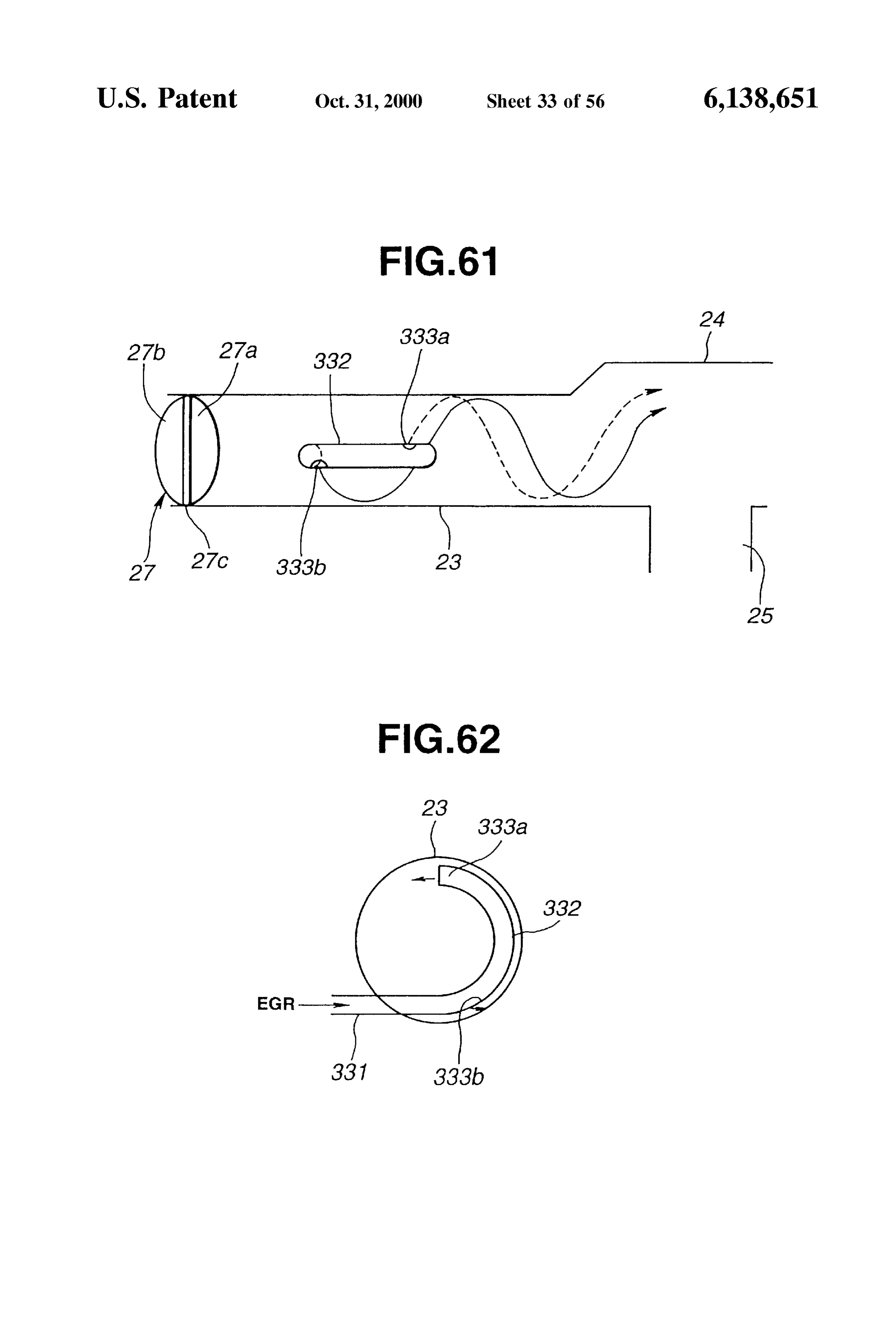
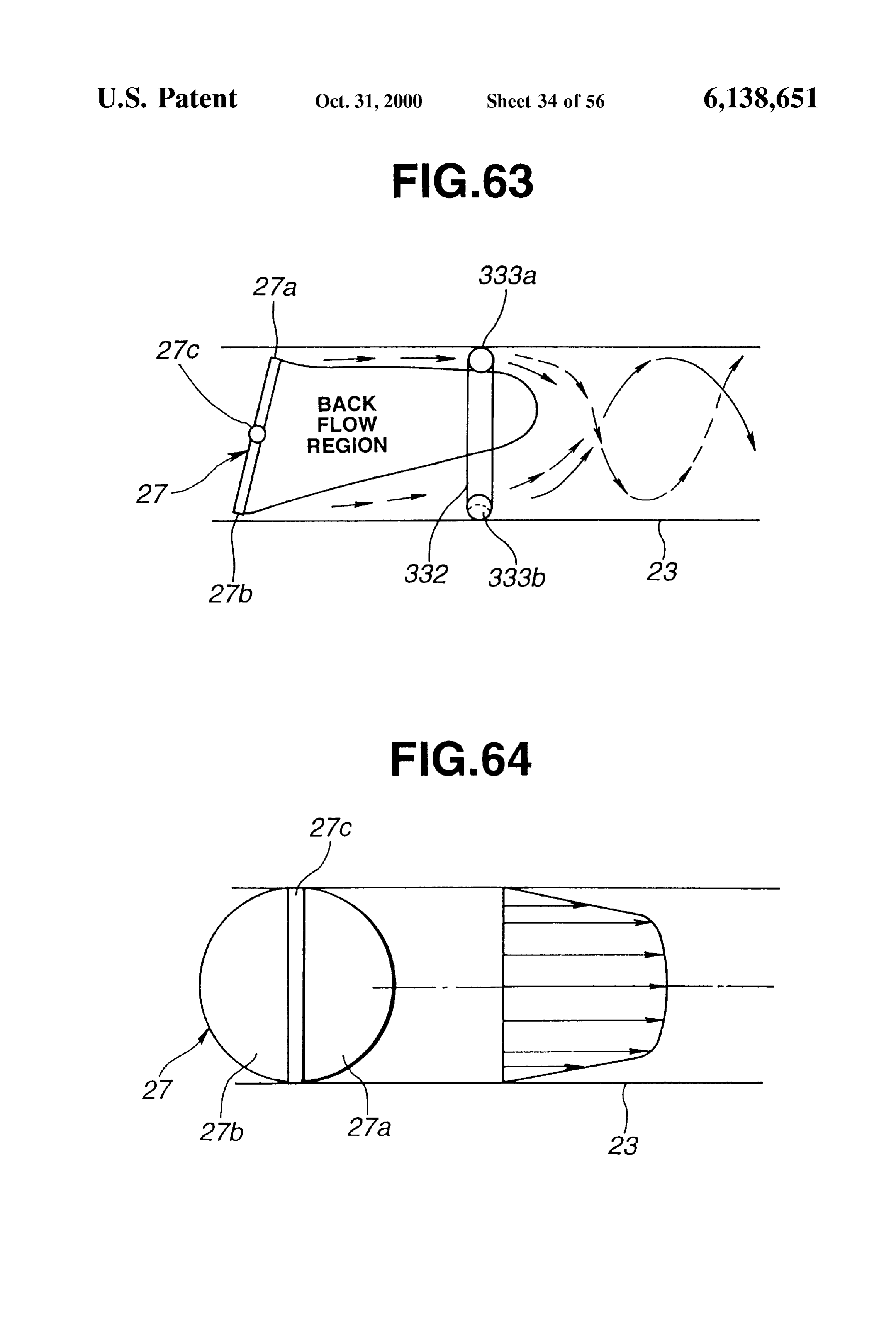
the EGR stream from the EGR introduction opening of FIG. FIG. 60 is a schematic vertical longitudinal sectional view 35. showing the positions of the EGR introduction openings of FIG. 38 is a schematic horizontal longitudinal sectional 55 FIG. 59 relative to a back flow region. view for illustrating a travel distance of the EGR gas FIG. 61 is a schematic horizontal longitudinal sectional discharged from the EGR introduction opening of FIG. 35. view showing the EGR introduction openings of FIG. 59. (The term “horizontal” means that the section is parallel to, FIG. 62 is a cross sectional view showing EGR introduc or coincident with, the Swing axis of the throttle valve.) tion openings according to a Seventeenth embodiment. FIGS. 39A and 39B are schematic cross sectional views 60 FIG. 63 is a schematic vertical longitudinal sectional view for showing a radial (or centripetal) EGR introduction mode showing the EGR introduction openings of FIG. 62. and a tangential EGR introduction mode for comparison. FIG. 64 is a schematic horizontal longitudinal sectional FIG. 40 is a graph for showing deposit formation in the view for illustrating the flow velocity distribution in the radial EGR introduction mode and the tangential EGR intake passage.
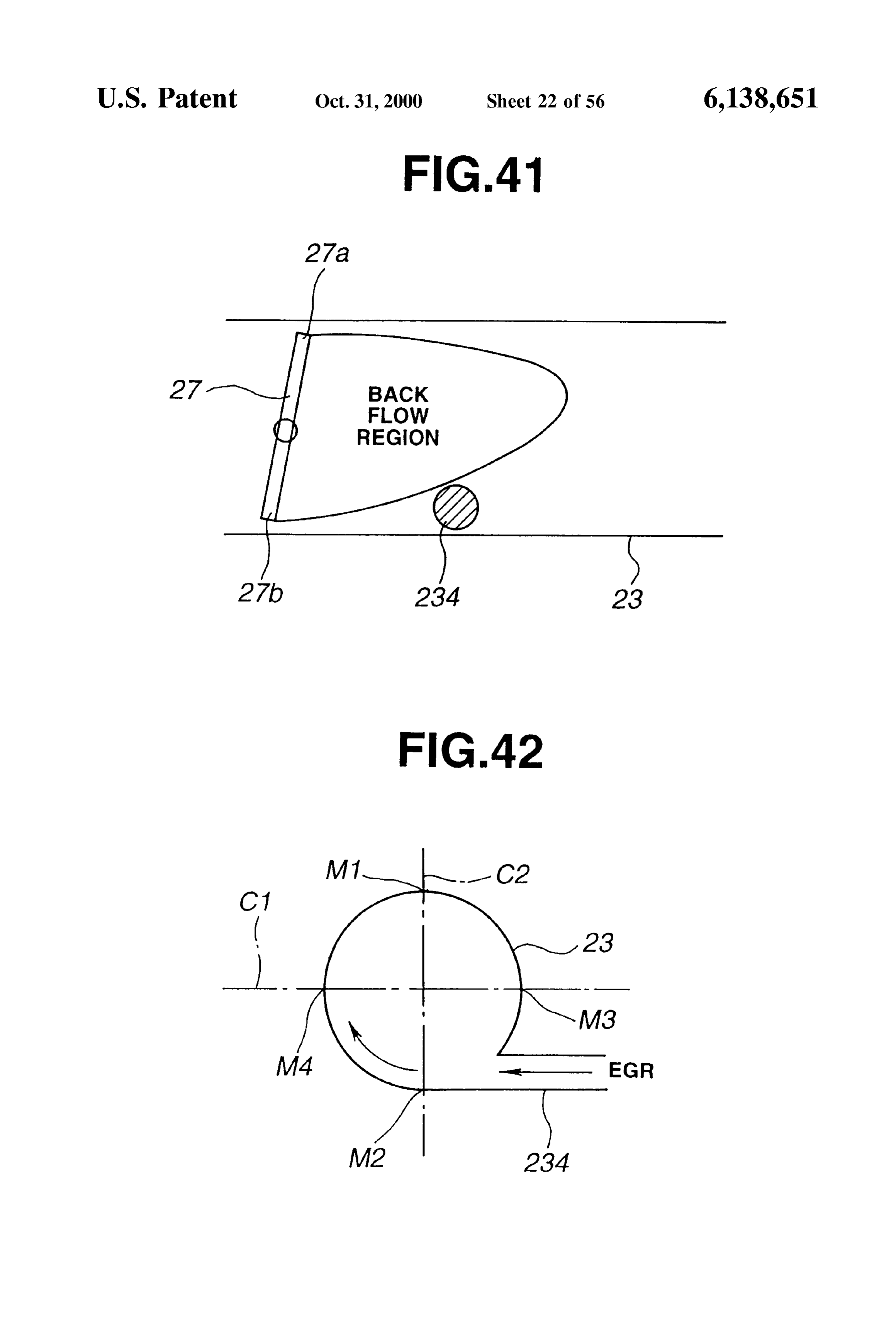
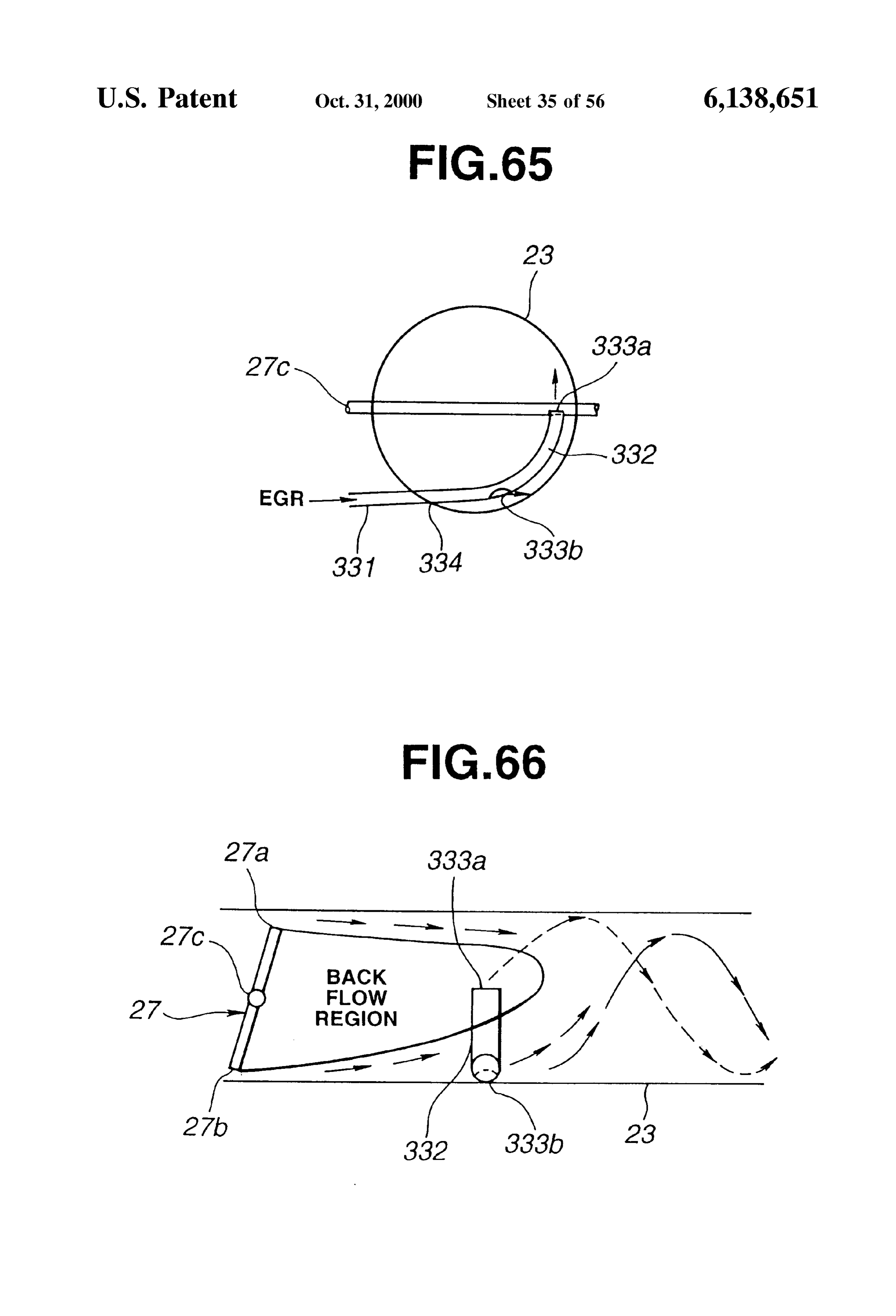
introduction mode for comparison. 65 FIG. 65 is a schematic cross sectional view showing EGR FIG. 41 is a schematic vertical longitudinal sectional view introduction openings according to an eighteenth embodi for showing an EGR introduction opening according to a ment.
Page 60
S 6
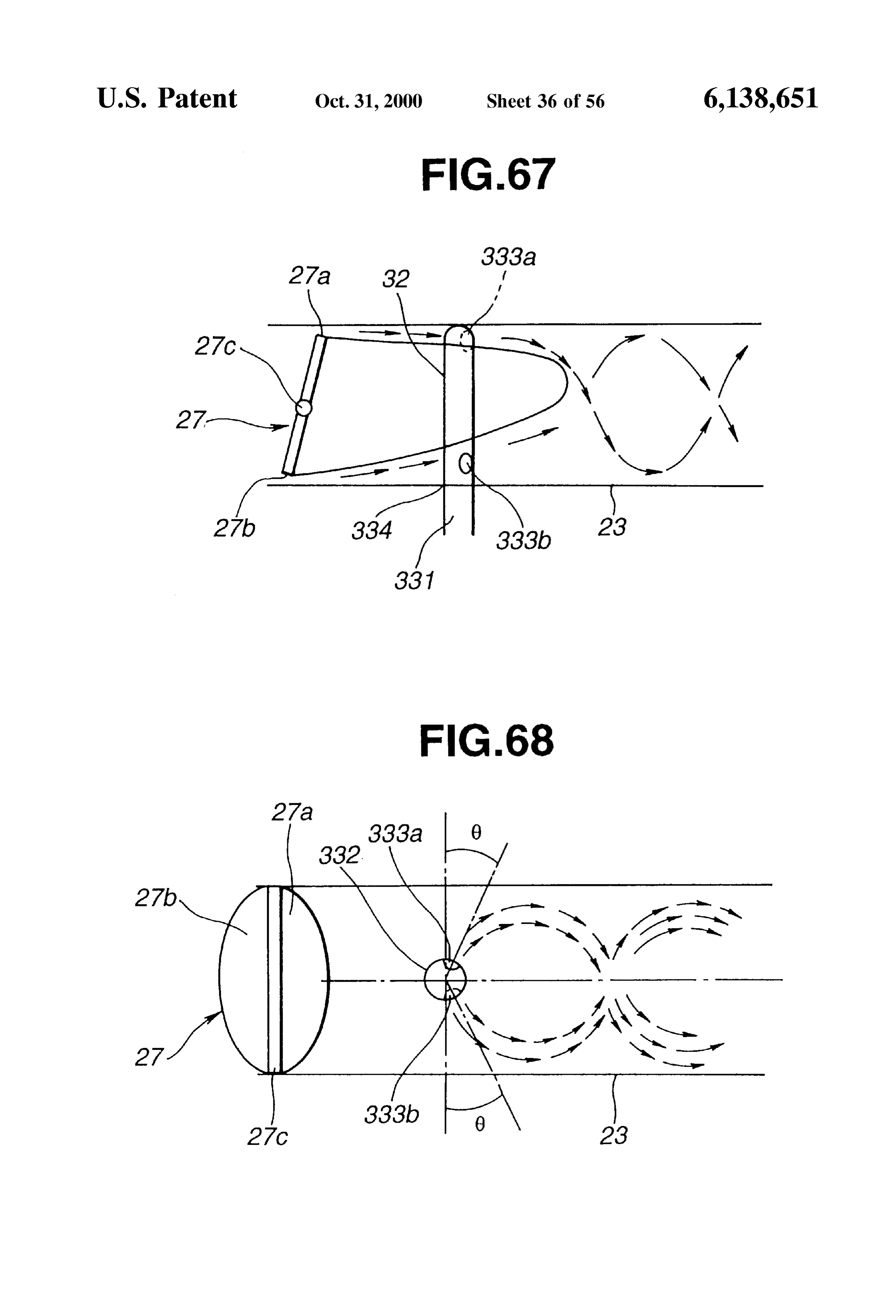
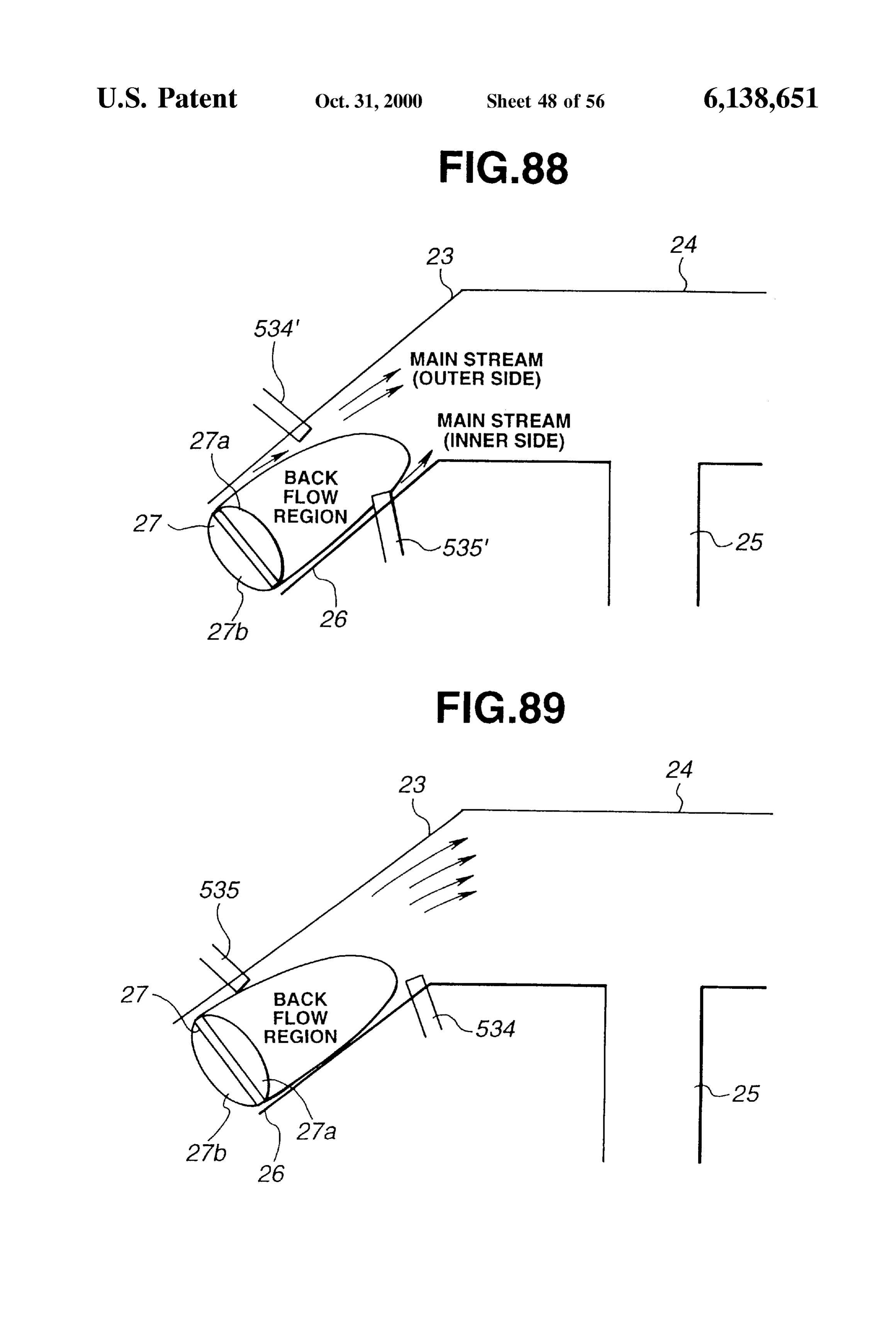
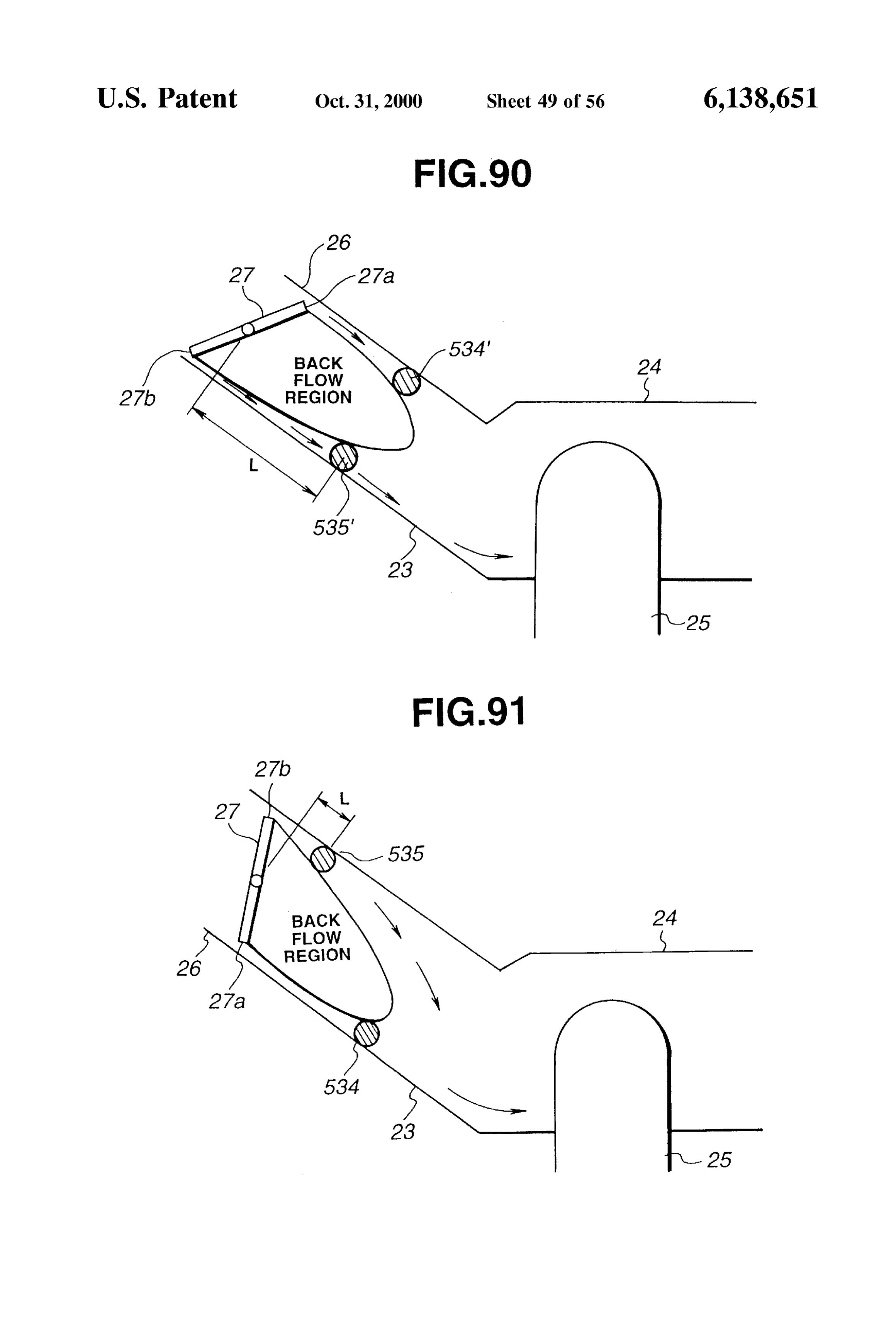
FIG. 66 is a schematic vertical longitudinal sectional view FIG. 91 is a schematic vertical longitudinal sectional view showing the EGR introduction openings of FIG. 65. showing EGR introduction openings according to the thirty FIG. 67 is a schematic vertical longitudinal sectional view first embodiment.
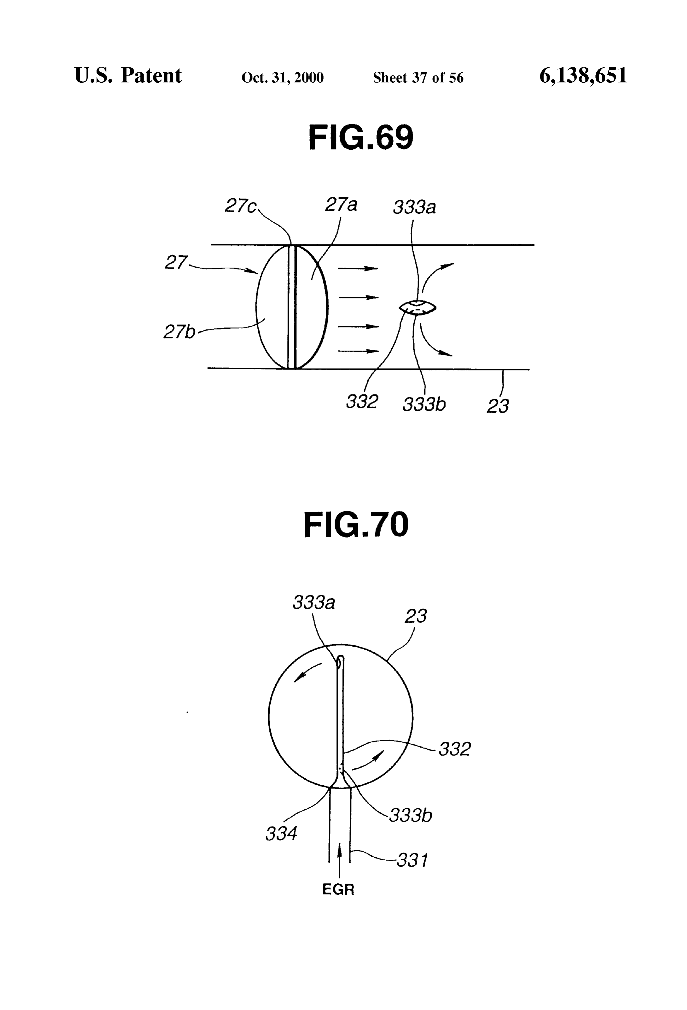
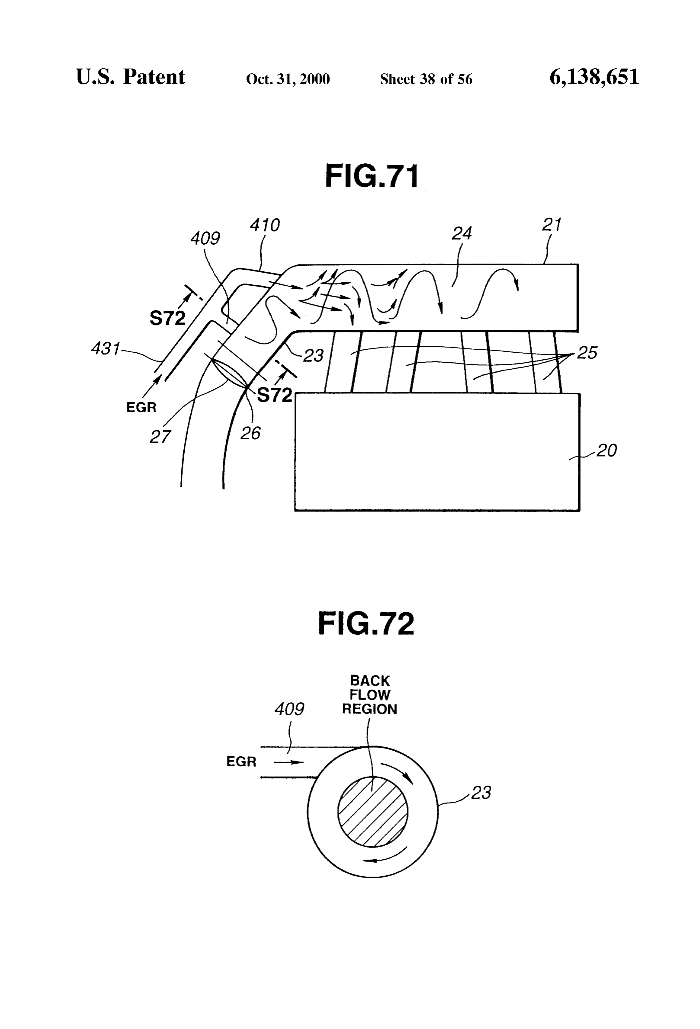
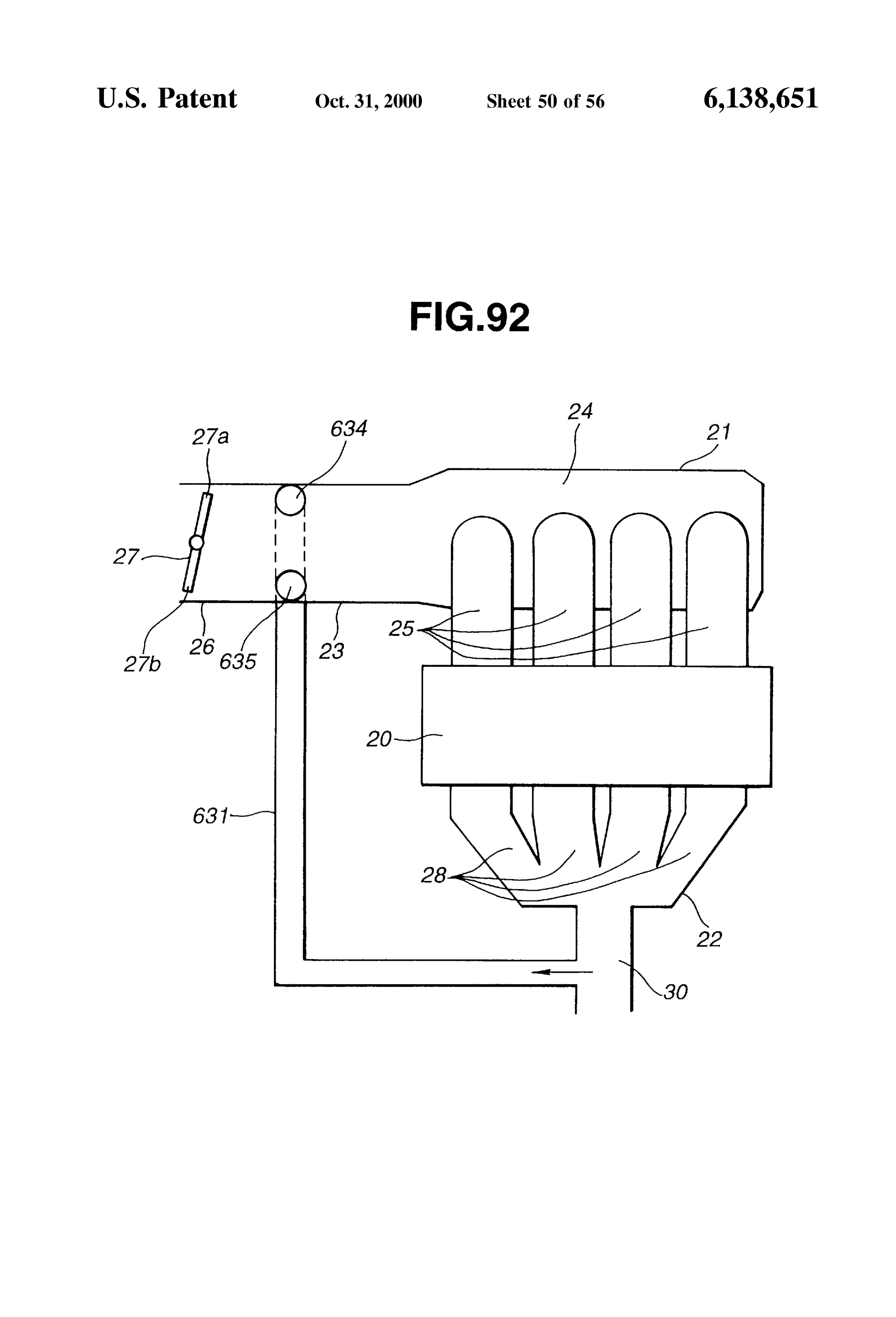
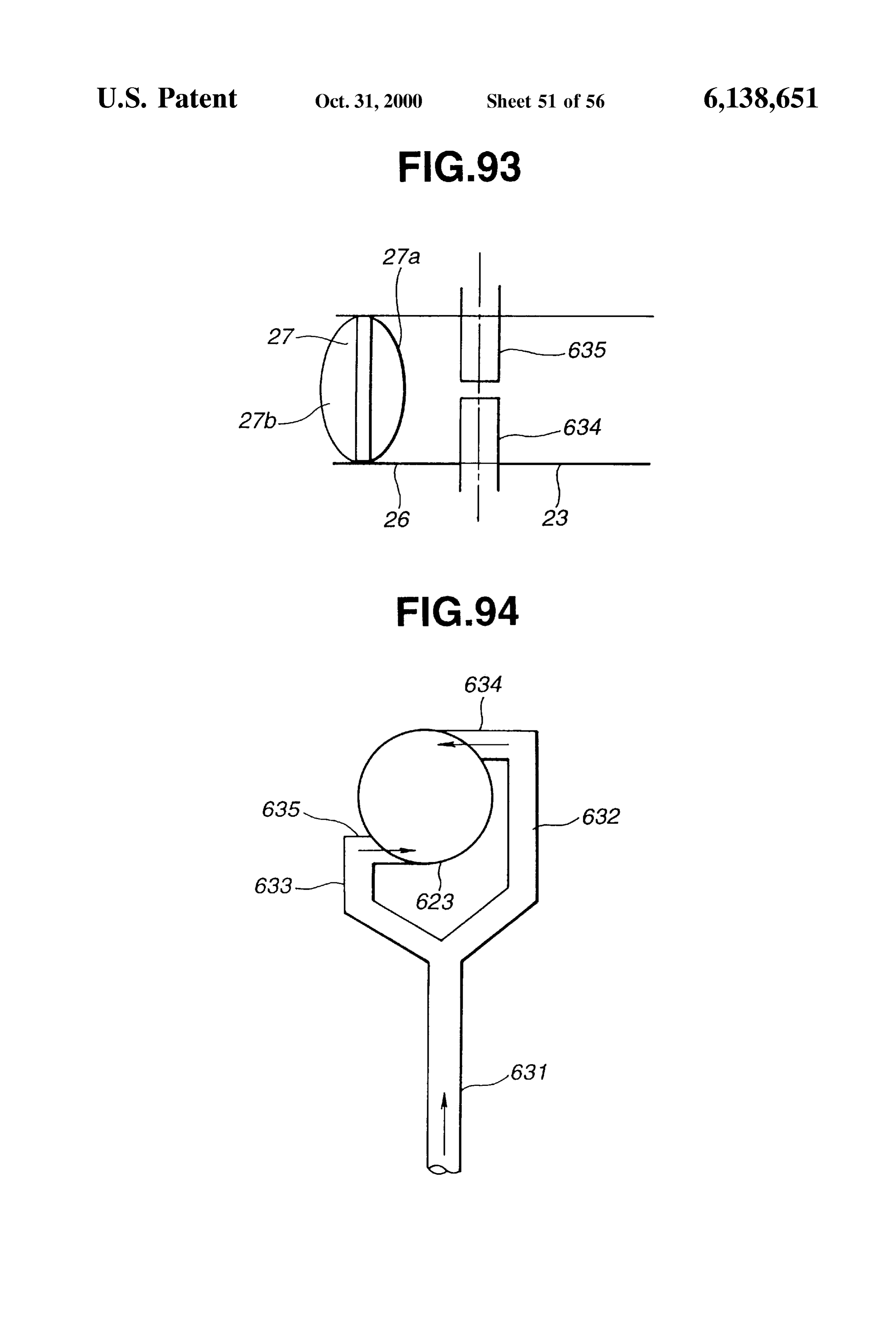
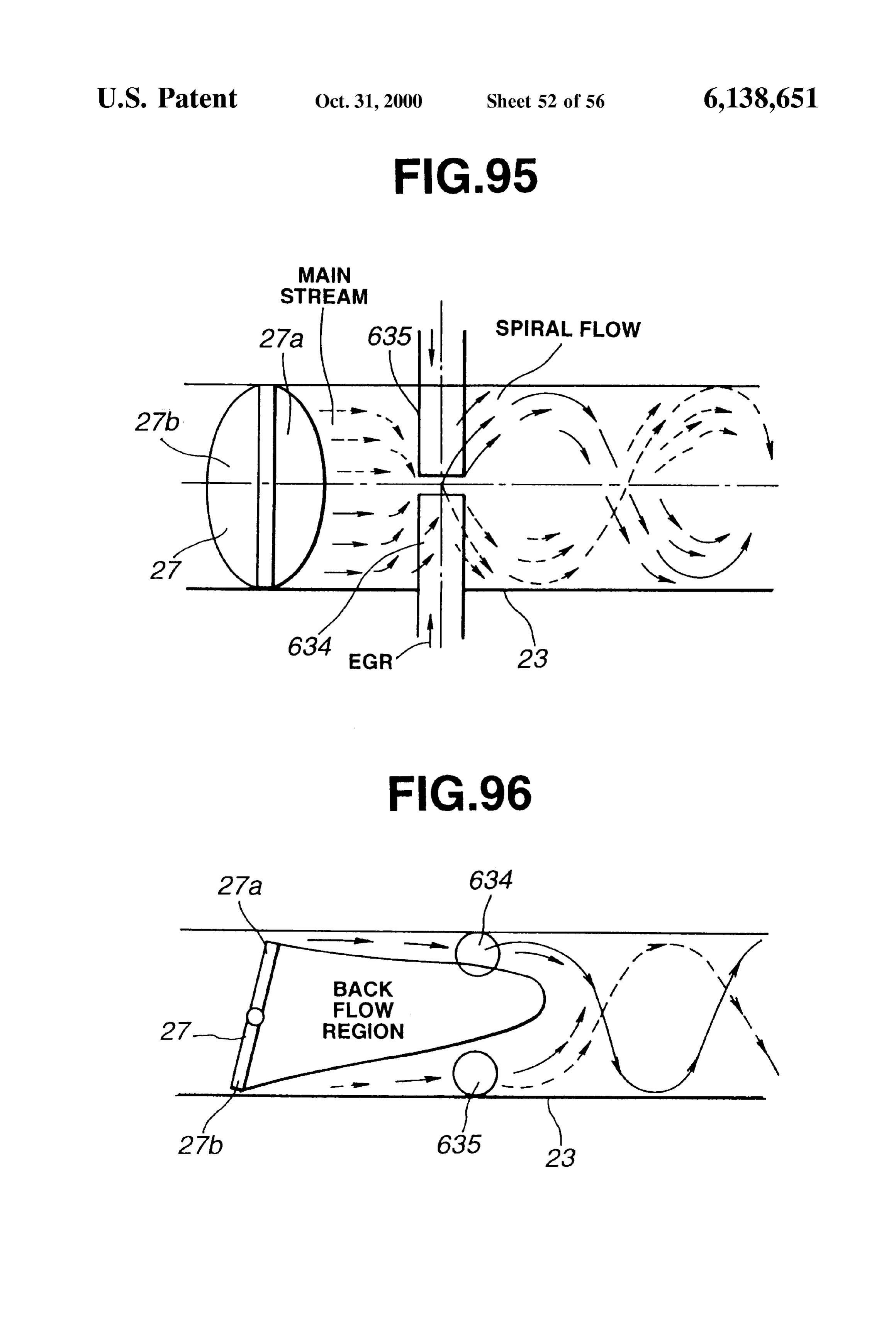
showing EGR introduction openings according to a nine FIG. 92 is a Schematic view showing an engine System teenth embodiment. according to a thirty-Second embodiment. FIG. 68 is a schematic horizontal longitudinal sectional FIG. 93 is a schematic horizontal longitudinal sectional view showing the EGR introduction openings of FIG. 67. View of an intake passage for showing EGR introduction FIG. 69 is a schematic horizontal longitudinal sectional openings of the engine system of FIG. 92. View showing EGR introduction openings according to a 1O FIG. 94 is a schematic cross sectional view showing the twentieth embodiment. EGR introduction openings of FIG. 93. FIG. 70 is a cross sectional view showing an engine FIG. 95 is a schematic horizontal longitudinal sectional System according to a twenty-first embodiment. view for showing streams produced by the EGR introduction FIG. 72 is a Schematic croSS Sectional view showing an openings of FIG. 93.
upstream EGR introduction openings of the engine System 15 FIG. 96 is a schematic vertical longitudinal sectional view of FIG 71. for showing the streams produced by the EGR introduction FIG. 73 is a schematic cross sectional view showing an openings of FIG. 93.
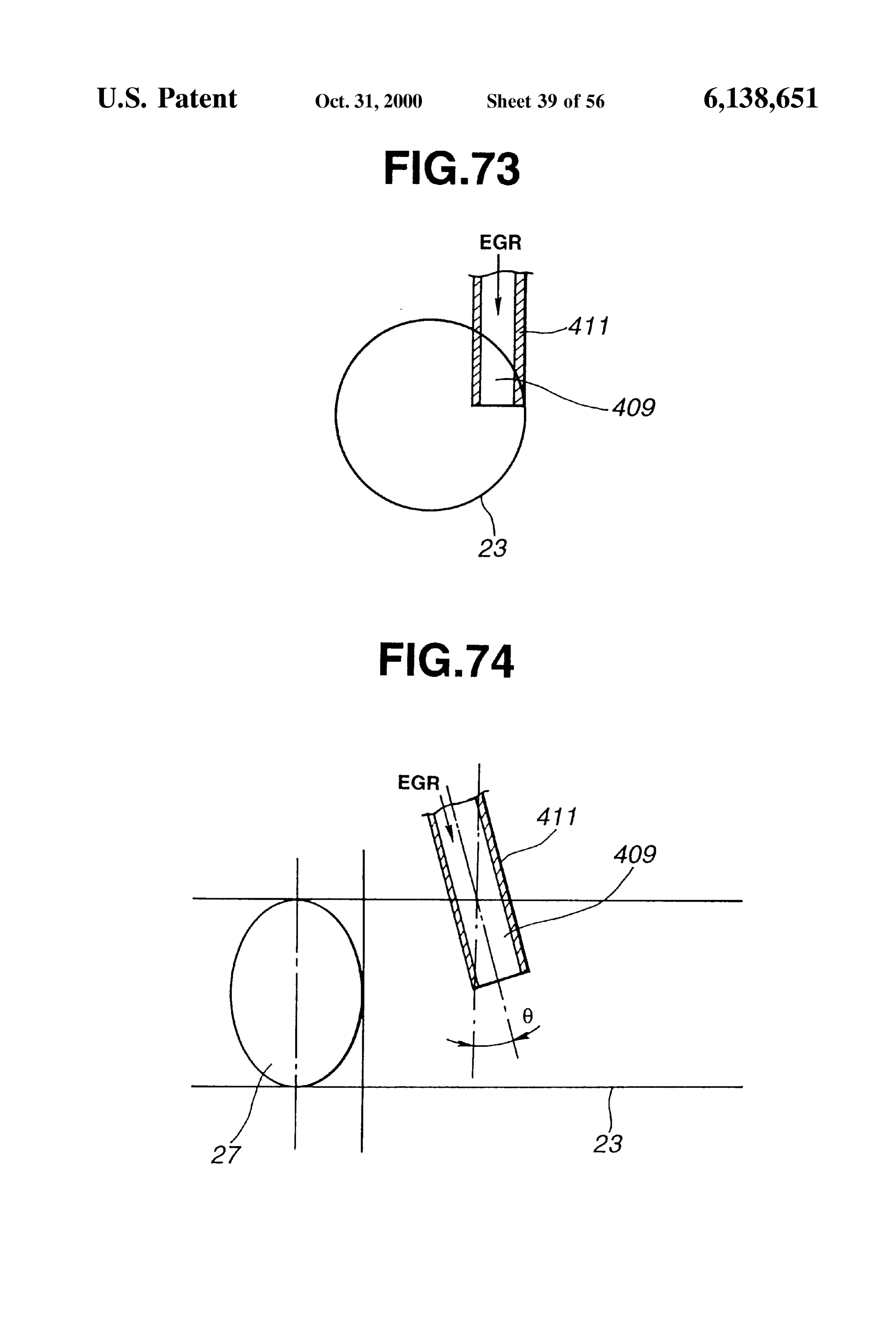
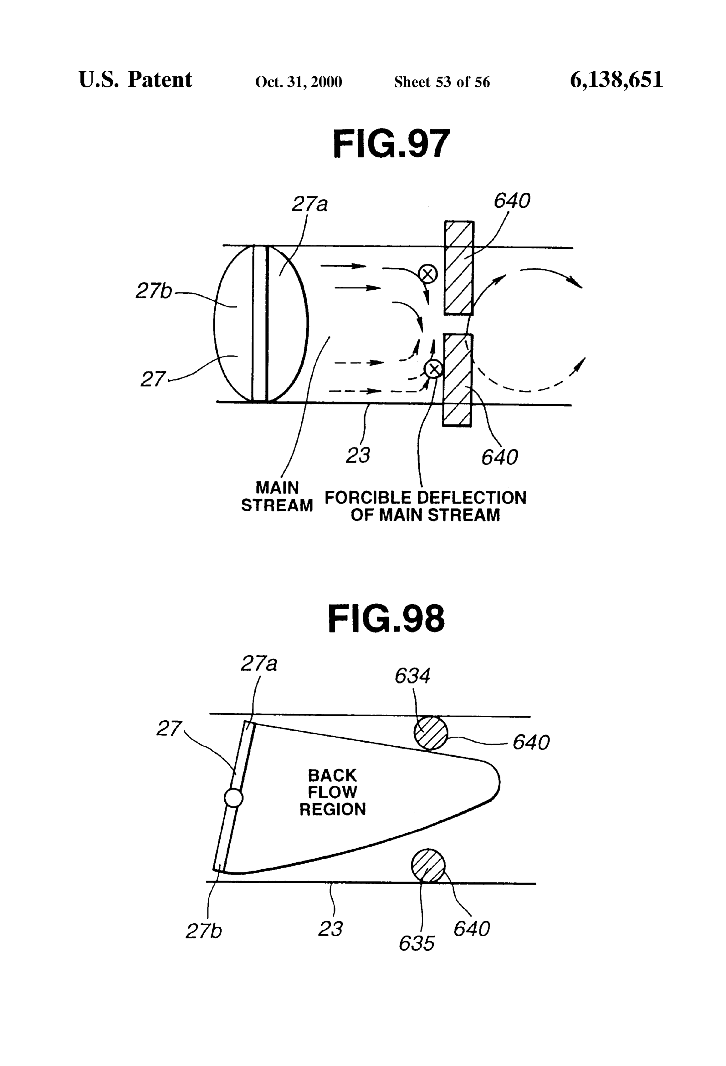
upstream EGR introduction opening according to a twenty FIG. 97 is a schematic horizontal longitudinal sectional Second embodiment. View showing EGR introduction openings according to a FIG. 74 is a schematic horizontal longitudinal sectional thirty-third embodiment.
View showing the upstream EGR introduction opening of FIG. 98 is a schematic vertical longitudinal sectional view
showing the EGR introduction openings of FIG. 97.
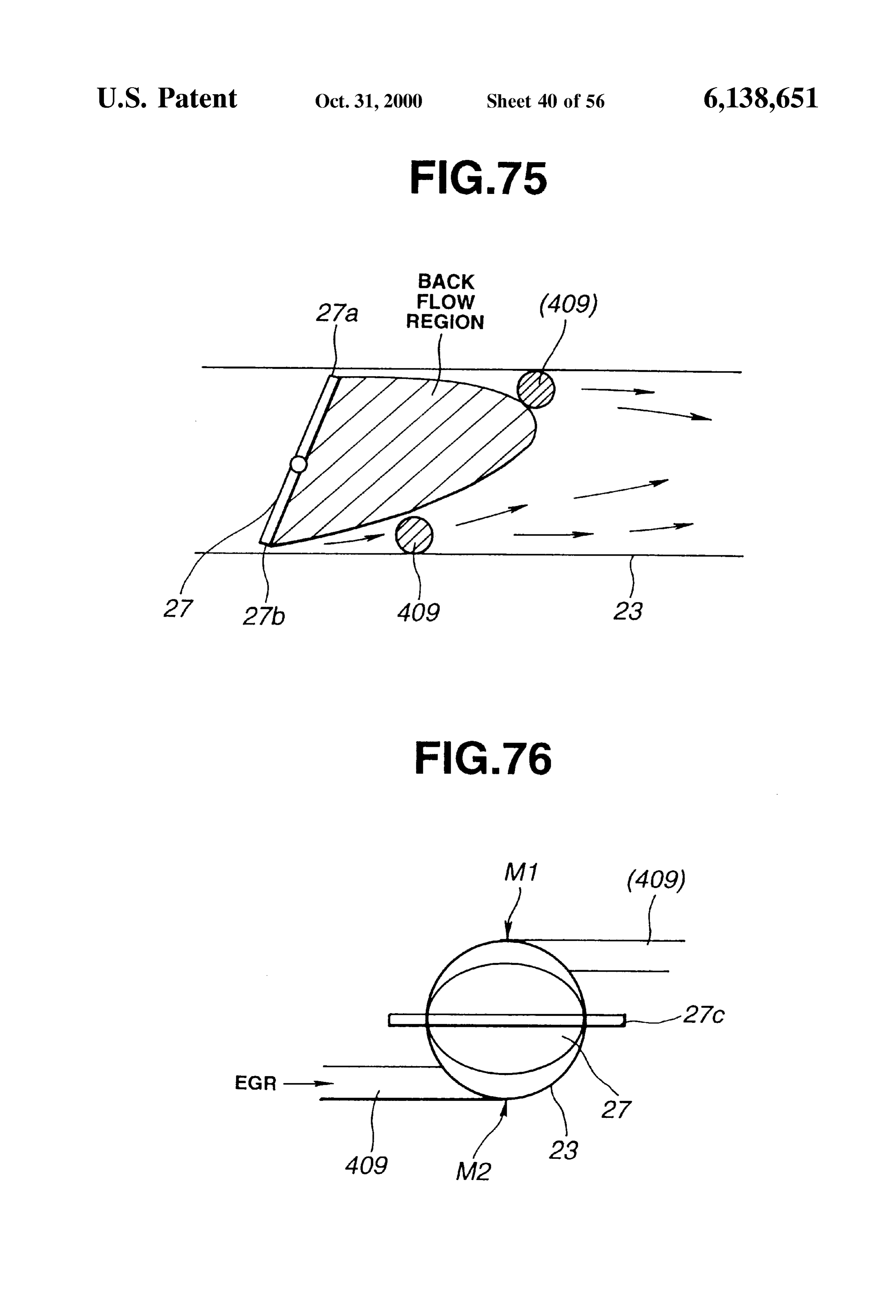
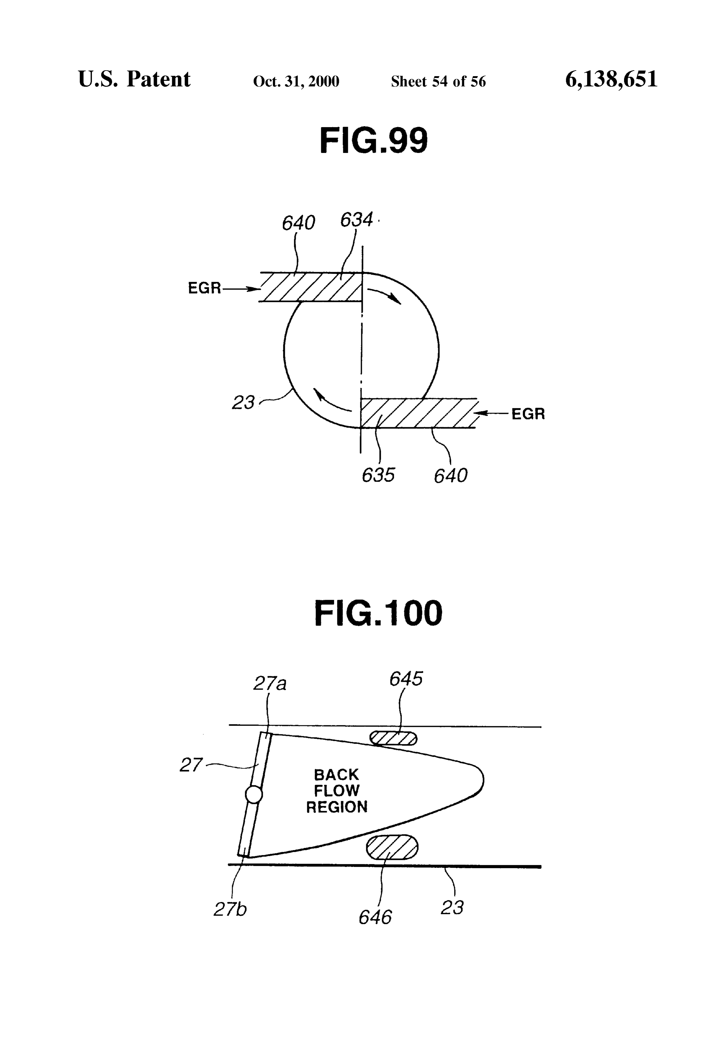
FIG. 75 is a schematic vertical longitudinal sectional view FIG. 99 is a schematic cross sectional view showing the showing an upstream EGR introduction opening according EGR introduction openings of FIG. 97. to a twenty-third embodiment. 25
FIG.
FIG. 76 is a schematic cross sectional view showing the View showing 100 is a schematic vertical longitudinal sectional upstream EGR introduction opening of FIG. 75. EGR introduction openings according to a thirty-fourth embodiment.
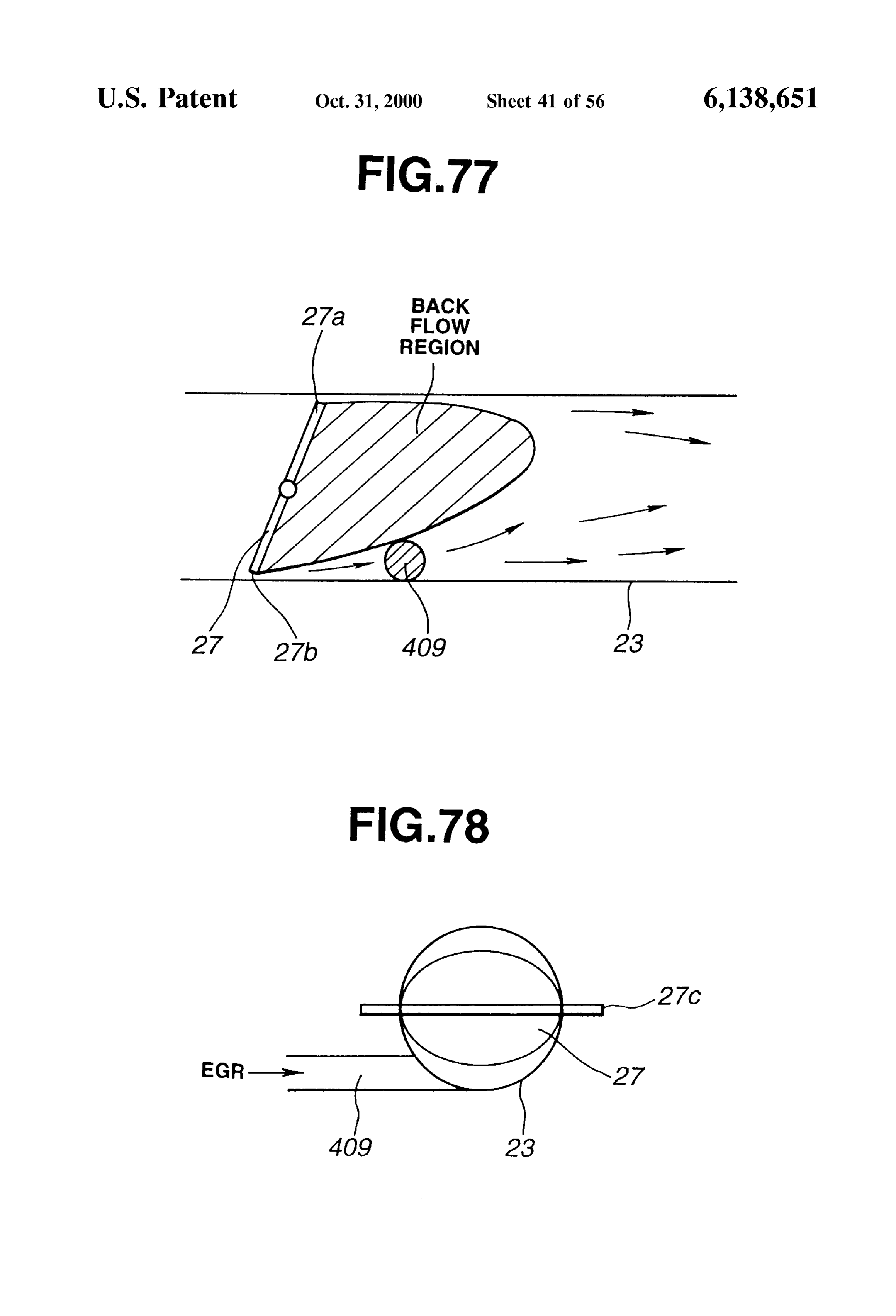
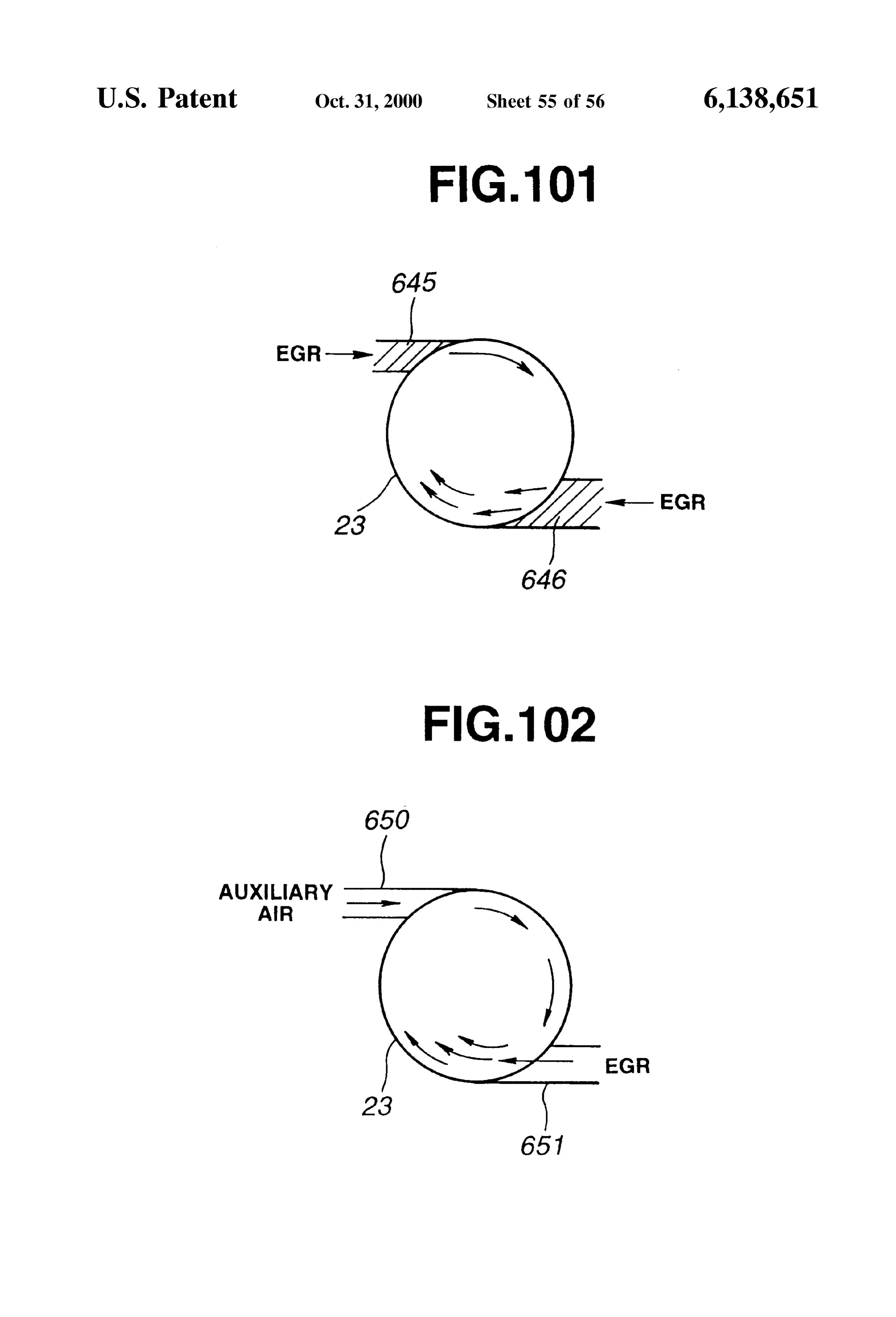
FIG. 77 is a schematic vertical longitudinal sectional view FIG. 101 is a schematic cross sectional view showing the showing an upstream EGR introduction opening according EGR introduction openings of FIG. 100. to a twenty-fourth embodiment.
FIG.
FIG. 78 is a schematic cross sectional view showing the EGR introduction102 is a schematic cross sectional view showing upstream EGR introduction opening of FIG. 77. opening and auxiliary air introduction opening according to a thirty-fifth embodiment.
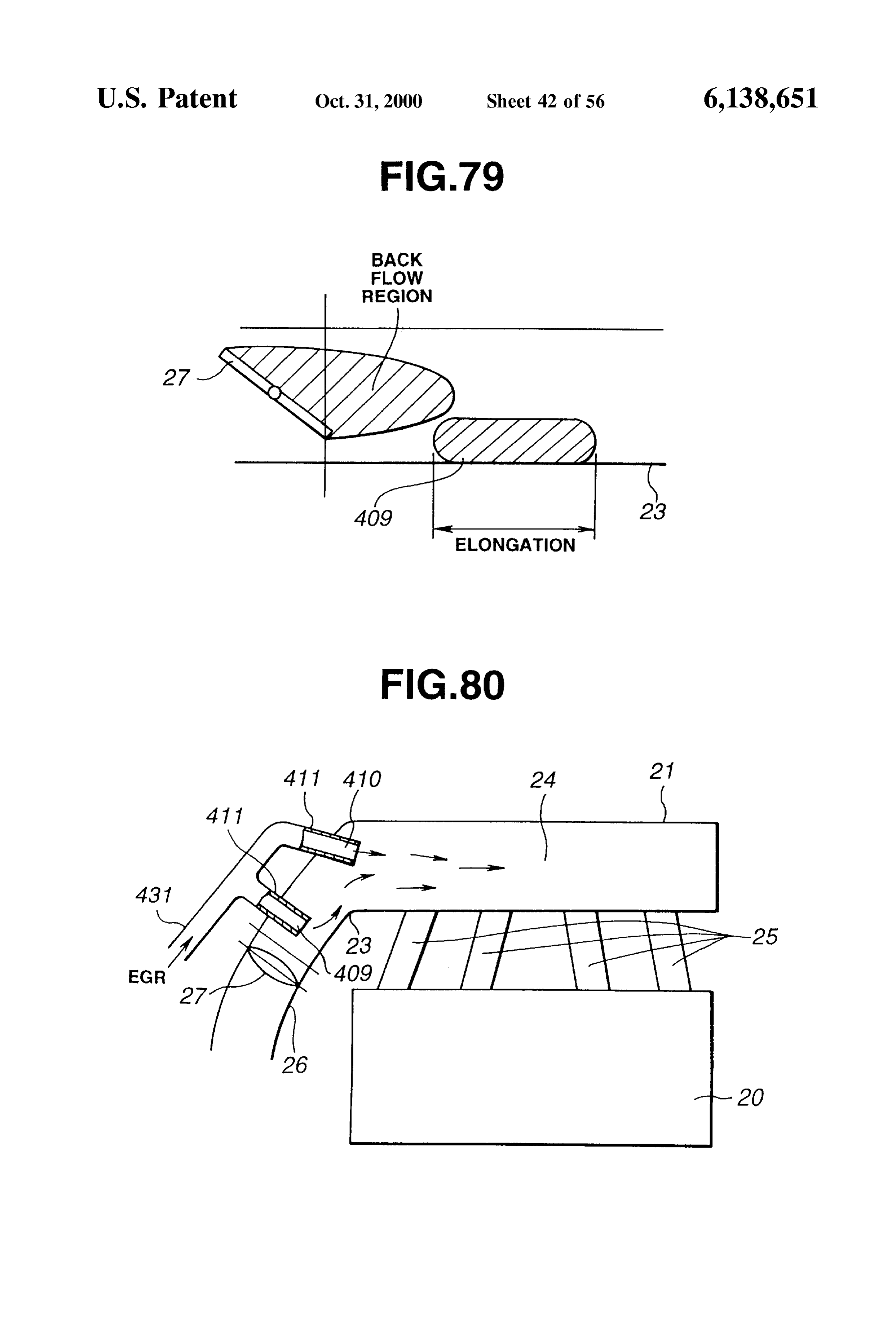
FIG. 79 is a schematic vertical longitudinal sectional view FIG. 103 is a graph for illustrating a thirty-sixth embodi showing an upstream EGR introduction opening according 35 ment.
to a twenty-fifth embodiment.
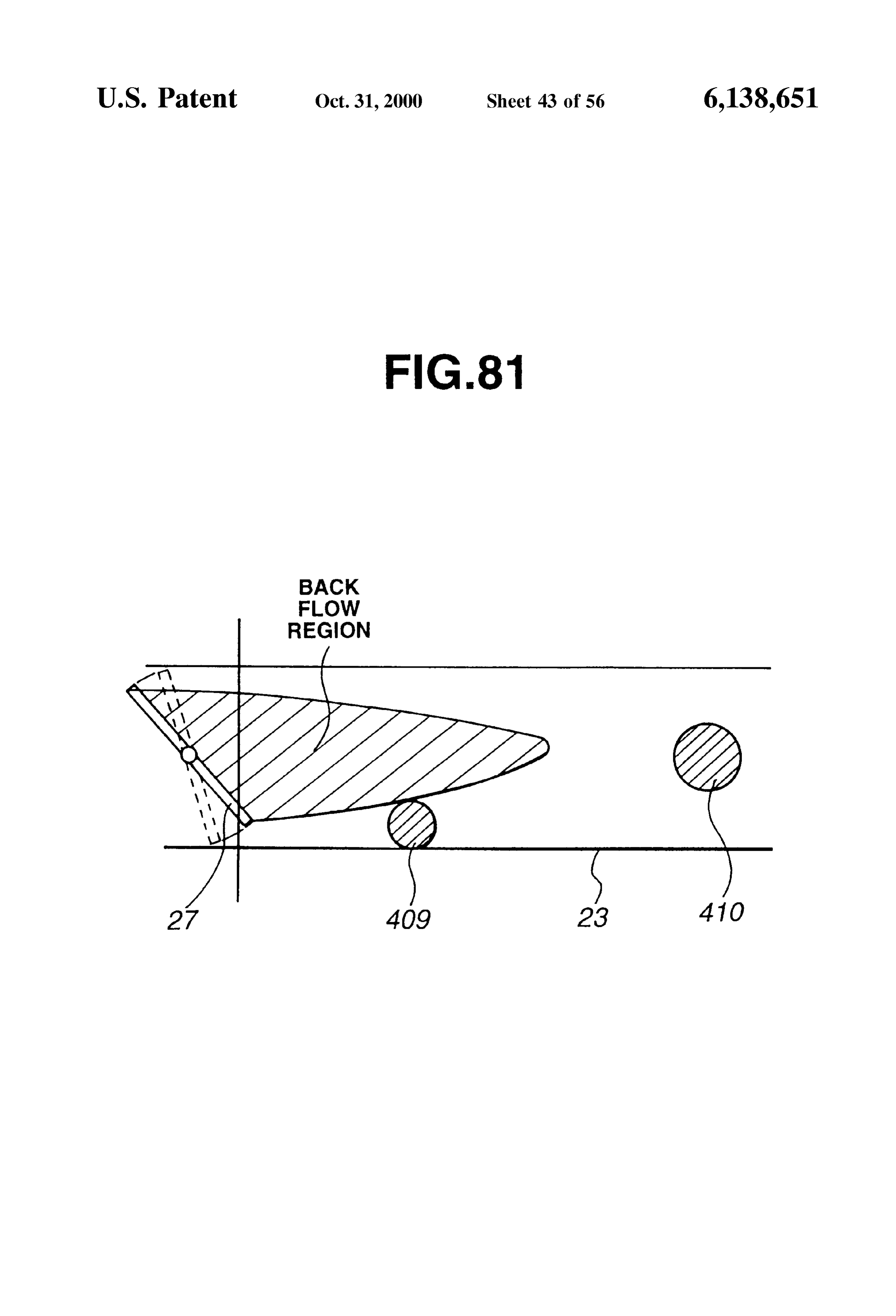
FIG. 80 is a schematic view showing an engine system EGR FIG. 104 is a schematic vertical sectional view showing according to a twenty-Sixth embodiment. introduction openings according to a thirty-Seventh embodiment.
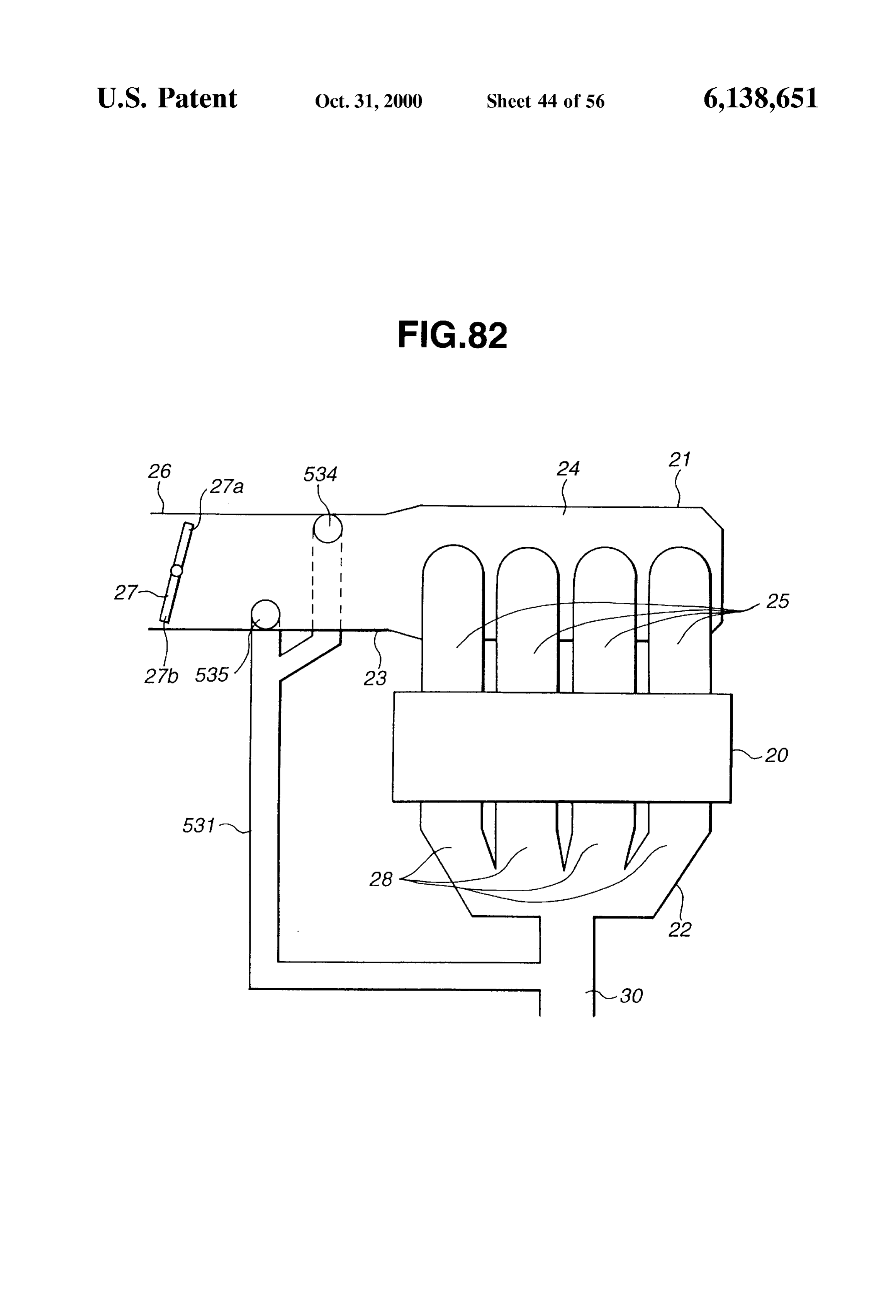
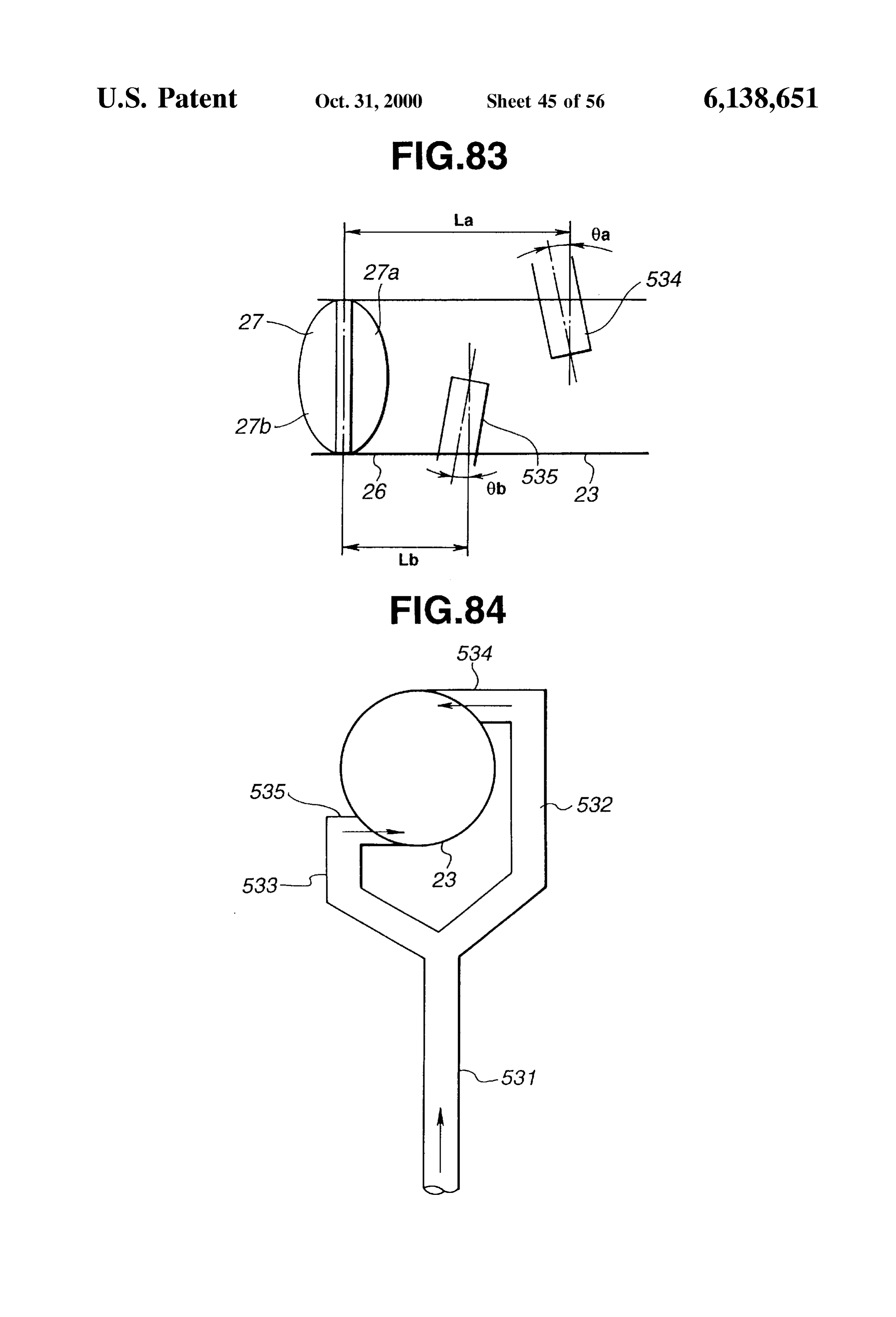
FIG. 81 is a schematic vertical longitudinal sectional view showing EGR introduction openings according to a twenty 40 DETAILED DESCRIPTION OF THE Seventh embodiment. INVENTION FIG. 82 is a Schematic view showing an engine System according to a twenty-eighth embodiment. 1st Embodiment FIG. 83 is a schematic horizontal longitudinal sectional FIGS. 1-3 show an engine System according to a first View showing EGR introduction openings of the engine 45 embodiment of the present invention.
system of FIG. 82. The engine System shown in FIG. 1 comprises an engine FIG. 84 is a schematic cross sectional view showing the 20, an intake System, an exhaust System, and an EGR System EGR introduction openings of FIG. 83. for returning part of the exhaust gas as EGR gas from the FIG. 85 is a schematic horizontal longitudinal sectional 50 exhaust System to the intake System.
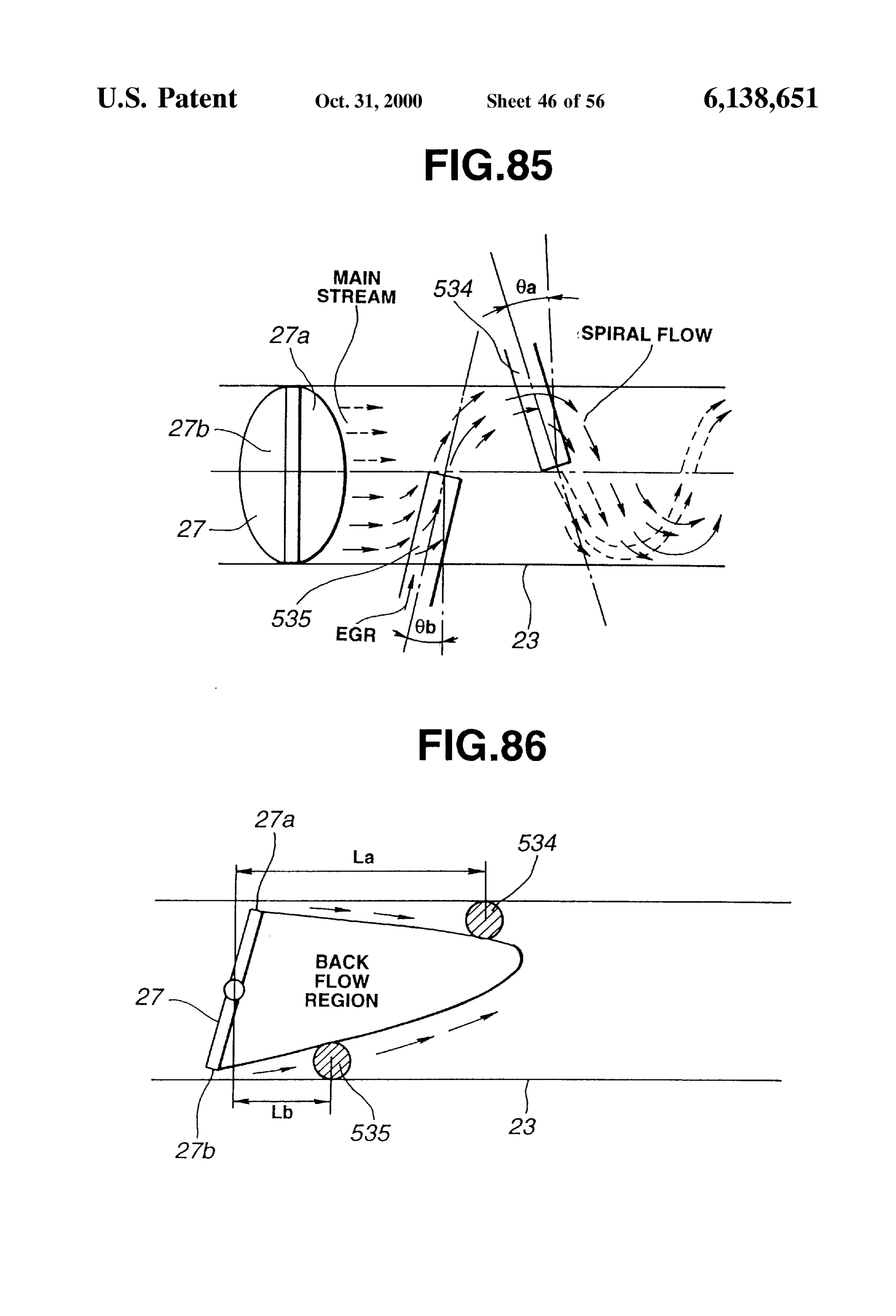
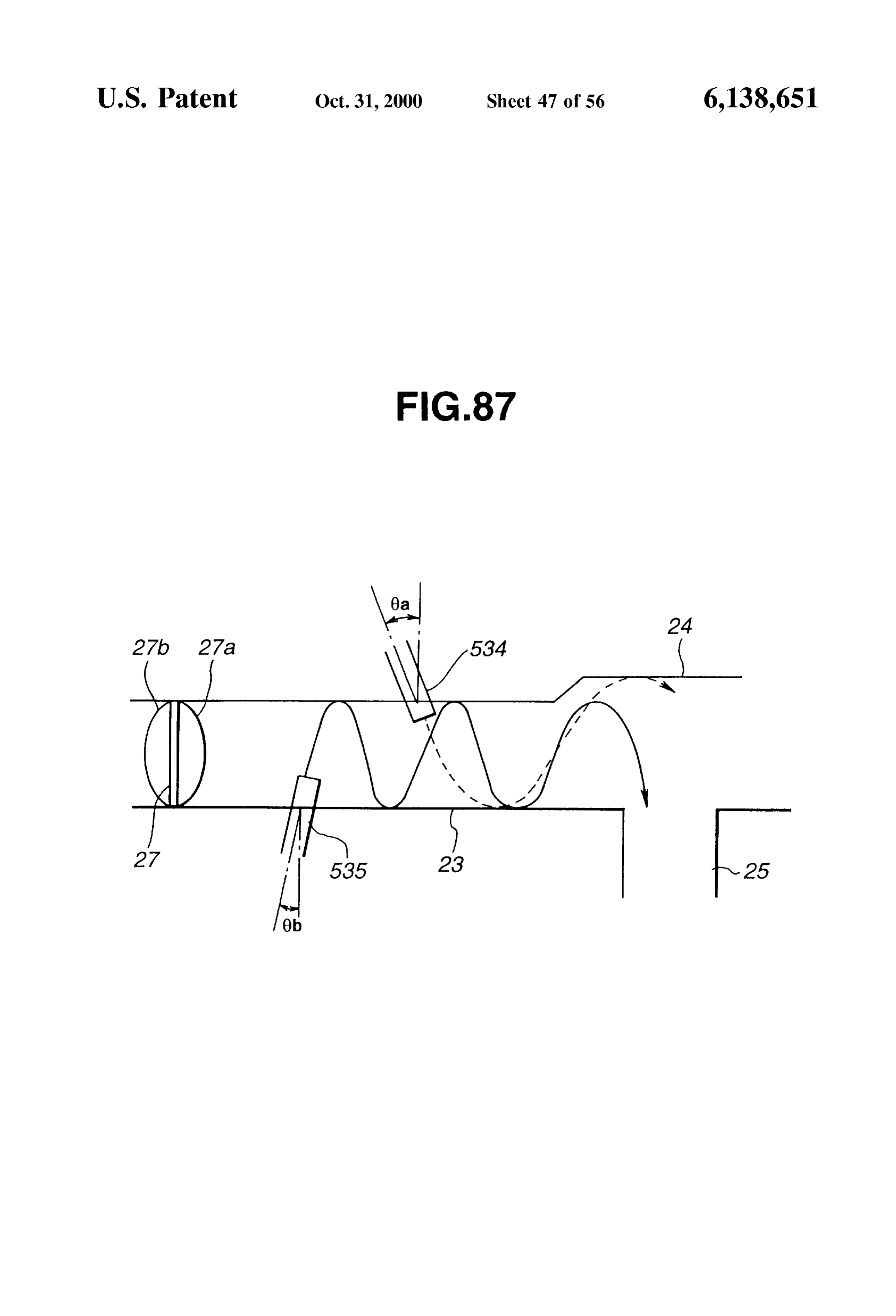
view showing EGR streams produced by the EGR introduc The intake System comprises a piping (or pipe arrange tion opening of FIG. 83. ment or pipe System) for distributing intake air to cylinders FIG. 86 is a schematic vertical longitudinal sectional view of the engine 20. The intake piping of this example includes for showing the positions of the EGR introduction openings an intake manifold 21 and a throttle body (throttle chamber) of FIG. 83. 55 26 for defining an intake passage System for distributing the FIG. 87 is a schematic horizontal longitudinal sectional intake air to the engine cylinders. The exhaust System View showing EGR introduction openings according to a comprises an exhaust manifold 22 for carrying exhaust gas twenty-ninth embodiment. away from the cylinders of the engine 20. FIG. 88 is a schematic horizontal longitudinal sectional The intake manifold 21 of this example includes an inlet View for showing a bend in an intake System according to a 60 pipe Section 23, a collector Section 24 of a predetermined thirtieth embodiment. Volume extending from the inlet pipe Section 23, and a Set FIG. 89 is a schematic horizontal longitudinal sectional of branches 25 extending from the collector section 24 to the View showing EGR introduction openings according to the cylinders of the engine 20, respectively. thirtieth embodiment. The throttle body 26 is connected with the intake mani FIG. 90 is a schematic vertical longitudinal sectional view 65 fold 21 on the upstream side of the inlet pipe section 23. The showing a bend in an intake System according to a thirty-first throttle body 26 and the inlet section 23 define an intake air embodiment. passage for introducing the intake air to the collector Section
Page 61
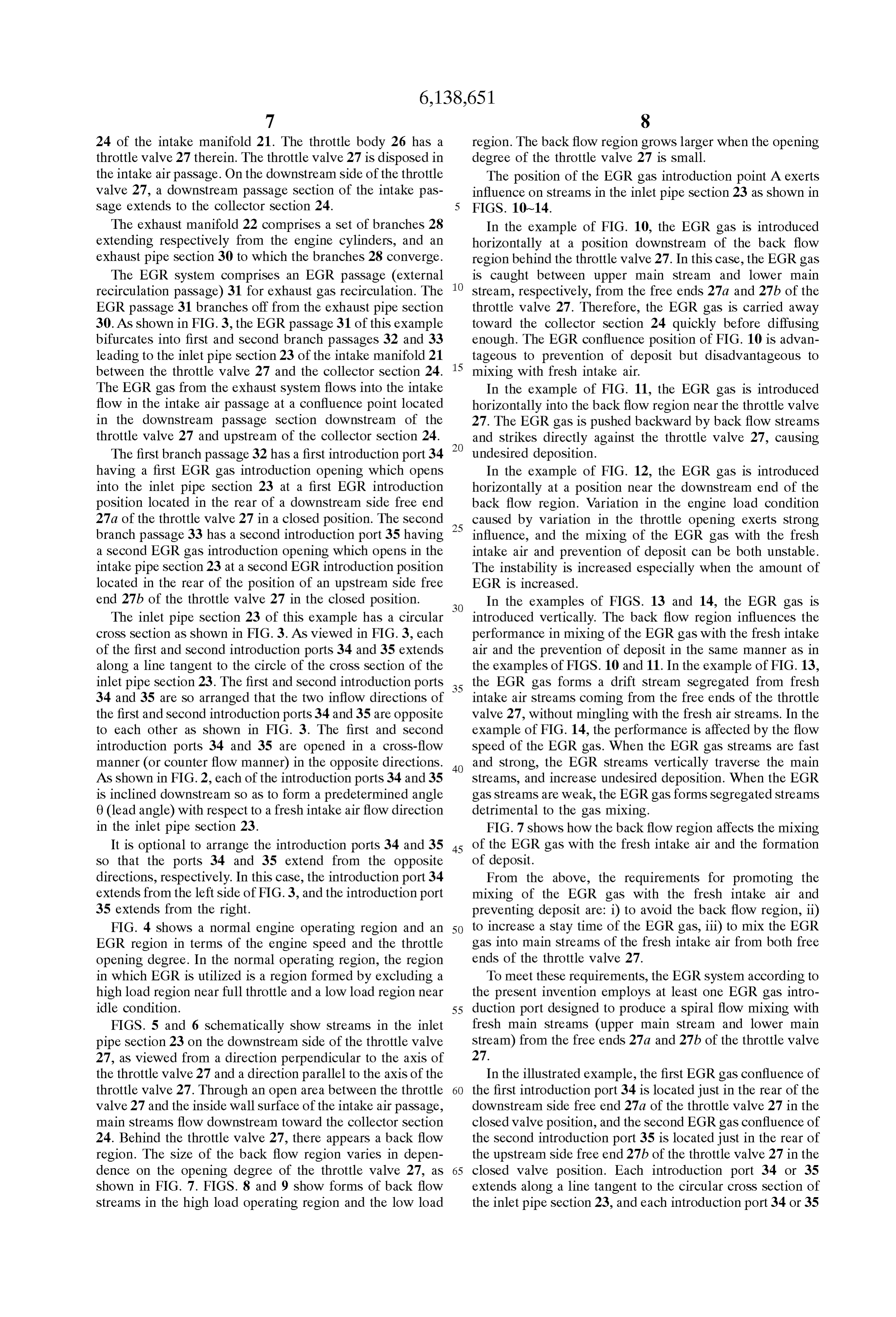
24 of the intake manifold 21. The throttle body 26 has a region. The back flow region grows larger when the opening throttle valve 27 therein. The throttle valve 27 is disposed in degree of the throttle valve 27 is small. the intake air passage. On the downstream Side of the throttle The position of the EGR gas introduction point A exerts Valve 27, a downstream passage Section of the intake pas influence on Streams in the inlet pipe Section 23 as shown in Sage extends to the collector Section 24. FIGS. 10-14.
The exhaust manifold 22 comprises a set of branches 28 In the example of FIG. 10, the EGR gas is introduced extending respectively from the engine cylinders, and an horizontally at a position downstream of the back flow exhaust pipe section 30 to which the branches 28 converge. region behind the throttle valve 27. In this case, the EGR gas The EGR System comprises an EGR passage (external is caught between upper main Stream and lower main recirculation passage) 31 for exhaust gas recirculation. The stream, respectively, from the free ends 27a and 27b of the EGR passage 31 branches off from the exhaust pipe Section throttle valve 27. Therefore, the EGR gas is carried away 30. As shown in FIG. 3, the EGR passage 31 of this example toward the collector section 24 quickly before diffusing bifurcates into first and Second branch passages 32 and 33 enough. The EGR confluence position of FIG. 10 is advan leading to the inlet pipe section 23 of the intake manifold 21 tageous to prevention of deposit but disadvantageous to between the throttle valve 27 and the collector section 24. 15 mixing with fresh intake air.
The EGR gas from the exhaust system flows into the intake In the example of FIG. 11, the EGR gas is introduced flow in the intake air passage at a confluence point located horizontally into the back flow region near the throttle valve in the downstream passage Section downstream of the 27. The EGR gas is pushed backward by back flow streams throttle valve 27 and upstream of the collector section 24. and Strikes directly against the throttle valve 27, causing The first branch passage 32 has a first introduction port 34 undesired deposition.
having a first EGR gas introduction opening which opens In the example of FIG. 12, the EGR gas is introduced into the inlet pipe section 23 at a first EGR introduction horizontally at a position near the downstream end of the position located in the rear of a downstream Side free end back flow region. Variation in the engine load condition 27a of the throttle valve 27 in a closed position. The second 25 caused by variation in the throttle opening exerts Strong branch passage 33 has a Second introduction port 35 having influence, and the mixing of the EGR gas with the fresh a Second EGR gas introduction opening which opens in the intake air and prevention of deposit can be both unstable. intake pipe Section 23 at a Second EGR introduction position The instability is increased especially when the amount of located in the rear of the position of an upstream Side free EGR is increased.
end 27b of the throttle valve 27 in the closed position. In the examples of FIGS. 13 and 14, the EGR gas is The inlet pipe Section 23 of this example has a circular introduced vertically. The back flow region influences the cross section as shown in FIG. 3. As viewed in FIG. 3, each performance in mixing of the EGR gas with the fresh intake of the first and second introduction ports 34 and 35 extends air and the prevention of deposit in the same manner as in along a line tangent to the circle of the croSS Section of the the examples of FIGS. 10 and 11. In the example of FIG. 13, inlet pipe Section 23. The first and Second introduction ports 35 the EGR gas forms a drift Stream Segregated from fresh 34 and 35 are so arranged that the two inflow directions of intake air Streams coming from the free ends of the throttle the first and second introduction ports 34 and 35 are opposite valve 27, without mingling with the fresh air streams. In the to each other as shown in FIG. 3. The first and second example of FIG. 14, the performance is affected by the flow introduction ports 34 and 35 are opened in a cross-flow speed of the EGR gas. When the EGR gas streams are fast manner (or counter flow manner) in the opposite directions. 40 and Strong, the EGR Streams vertically traverse the main As shown in FIG.2, each of the introduction ports 34 and 35 streams, and increase undesired deposition. When the EGR is inclined downstream So as to form a predetermined angle gas Streams are weak, the EGR gas forms Segregated Streams 0 (lead angle) with respect to a fresh intake air flow direction detrimental to the gas mixing.
in the inlet pipe Section 23. FIG. 7 shows how the back flow region affects the mixing It is optional to arrange the introduction ports 34 and 35 45 of the EGR gas with the fresh intake air and the formation so that the ports 34 and 35 extend from the opposite of deposit.
directions, respectively. In this case, the introduction port 34 From the above, the requirements for promoting the extends from the left side of FIG. 3, and the introduction port mixing of the EGR gas with the fresh intake air and 35 extends from the right. preventing deposit are: i) to avoid the back flow region, ii) FIG. 4 shows a normal engine operating region and an 50 to increase a stay time of the EGR gas, iii) to mix the EGR EGR region in terms of the engine Speed and the throttle gas into main Streams of the fresh intake air from both free opening degree. In the normal operating region, the region ends of the throttle valve 27.
in which EGR is utilized is a region formed by excluding a To meet these requirements, the EGR System according to high load region near full throttle and a low load region near the present invention employs at least one EGR gas intro idle condition. 55 duction port designed to produce a spiral flow mixing with FIGS. 5 and 6 schematically show streams in the inlet fresh main Streams (upper main Stream and lower main pipe section 23 on the downstream side of the throttle valve stream) from the free ends 27a and 27b of the throttle valve 27, as viewed from a direction perpendicular to the axis of 27.
the throttle valve 27 and a direction parallel to the axis of the In the illustrated example, the first EGR gas confluence of throttle valve 27. Through an open area between the throttle 60 the first introduction port 34 is located just in the rear of the Valve 27 and the inside wall Surface of the intake air passage, downstream side free end 27a of the throttle valve 27 in the main Streams flow downstream toward the collector Section closed valve position, and the Second EGR gas confluence of 24. Behind the throttle valve 27, there appears a back flow the second introduction port 35 is located just in the rear of region. The size of the back flow region varies in depen the upstream side free end 27b of the throttle valve 27 in the dence on the opening degree of the throttle valve 27, as 65 closed valve position. Each introduction port 34 or 35 shown in FIG. 7. FIGS. 8 and 9 show forms of back flow extends along a line tangent to the circular croSS Section of Streams in the high load operating region and the low load the inlet pipe section 23, and each introduction port 34 or 35
Page 62
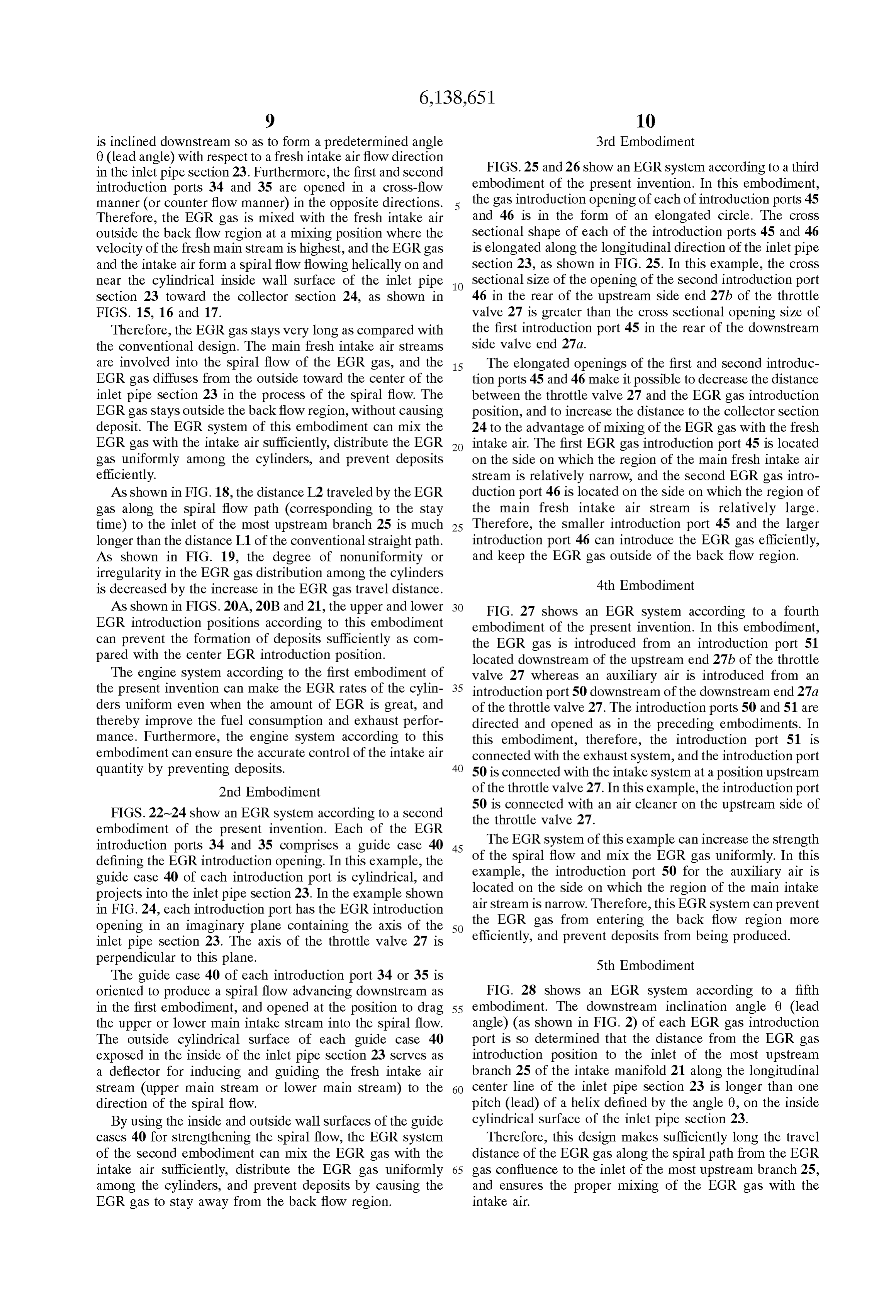
is inclined downstream So as to form a predetermined angle 3rd Embodiment 0 (lead angle) with respect to a fresh intake air flow direction FIGS. 25 and 26 show an EGR system according to a third in the inlet pipe Section 23. Furthermore, the first and Second introduction ports 34 and 35 are opened in a cross-flow embodiment of the present invention. In this embodiment, manner (or counter flow manner) in the opposite directions. the gas introduction opening of each of introduction ports 45 Therefore, the EGR gas is mixed with the fresh intake air and 46 is in the form of an elongated circle. The croSS outside the back flow region at a mixing position where the sectional shape of each of the introduction ports 45 and 46 Velocity of the fresh main Stream is highest, and the EGR gas is elongated along the longitudinal direction of the inlet pipe and the intake air form a spiral flow flowing helically on and section 23, as shown in FIG. 25. In this example, the cross near the cylindrical inside wall Surface of the inlet pipe 1O Sectional Size of the opening of the Second introduction port Section 23 toward the collector Section 24, as shown in 46 in the rear of the upstream side end 27b of the throttle FIGS. 15, 16 and 17. Valve 27 is greater than the croSS Sectional opening Size of Therefore, the EGR gas stays very long as compared with the first introduction port 45 in the rear of the downstream the conventional design. The main fresh intake air Streams side valve end 27a.
are involved into the spiral flow of the EGR gas, and the 15 The elongated openings of the first and Second introduc EGR gas diffuses from the outside toward the center of the tion ports 45 and 46 make it possible to decrease the distance inlet pipe section 23 in the process of the spiral flow. The between the throttle valve 27 and the EGR gas introduction EGR gas stays outside the back flow region, without causing position, and to increase the distance to the collector Section deposit. The EGR system of this embodiment can mix the 24 to the advantage of mixing of the EGR gas with the fresh EGR gas with the intake air sufficiently, distribute the EGR intake air. The first EGR gas introduction port 45 is located gas uniformly among the cylinders, and prevent deposits on the Side on which the region of the main fresh intake air efficiently. Stream is relatively narrow, and the Second EGR gas intro As shown in FIG. 18, the distance L2 traveled by the EGR duction port 46 is located on the Side on which the region of gas along the spiral flow path (corresponding to the Stay the main fresh intake air Stream is relatively large. time) to the inlet of the most upstream branch 25 is much 25 Therefore, the smaller introduction port 45 and the larger longer than the distance L1 of the conventional Straight path. introduction port 46 can introduce the EGR gas efficiently, As shown in FIG. 19, the degree of nonuniformity or and keep the EGR gas outside of the back flow region. irregularity in the EGR gas distribution among the cylinders is decreased by the increase in the EGR gas travel distance. 4th Embodiment As shown in FIGS. 20A, 20B and 21, the upper and lower FIG. 27 shows an EGR system according to a fourth EGR introduction positions according to this embodiment embodiment of the present invention. In this embodiment, can prevent the formation of deposits Sufficiently as com the EGR gas is introduced from an introduction port 51 pared with the center EGR introduction position. located downstream of the upstream end 27b of the throttle The engine System according to the first embodiment of valve 27 whereas an auxiliary air is introduced from an the present invention can make the EGR rates of the cylin 35 introduction port 50 downstream of the downstream end 27a derS uniform even when the amount of EGR is great, and of the throttle valve 27. The introduction ports 50 and 51 are thereby improve the fuel consumption and exhaust perfor directed and opened as in the preceding embodiments. In mance. Furthermore, the engine System according to this this embodiment, therefore, the introduction port 51 is embodiment can ensure the accurate control of the intake air connected with the exhaust System, and the introduction port quantity by preventing deposits. 40 50 is connected with the intake System at a position upstream 2nd Embodiment of the throttle valve 27. In this example, the introduction port FIGS. 22-24 show an EGR system according to a second the 50 is connected with an air cleaner on the upstream side of throttle valve 27.
embodiment of the present invention. Each of the EGR The EGR System of this example can increase the Strength introduction ports 34 and 35 comprises a guide case 40 45 defining the EGR introduction opening. In this example, the of the spiral flow and mix the EGR gas uniformly. In this guide case 40 of each introduction port is cylindrical, and example, the introduction port 50 for the auxiliary air is projects into the inlet pipe Section 23. In the example shown located on the Side on which the region of the main intake in FIG. 24, each introduction port has the EGR introduction the air Stream is narrow. Therefore, this EGR System can prevent opening in an imaginary plane containing the axis of the 50 EGR gas from entering the back flow region more inlet pipe section 23. The axis of the throttle valve 27 is efficiently, and prevent deposits from being produced. perpendicular to this plane. 5th Embodiment The guide case 40 of each introduction port 34 or 35 is oriented to produce a spiral flow advancing downstream as FIG. 28 shows an EGR system according to a fifth in the first embodiment, and opened at the position to drag 55 embodiment. The downstream inclination angle 0 (lead the upper or lower main intake Stream into the Spiral flow. angle) (as shown in FIG. 2) of each EGR gas introduction The outside cylindrical Surface of each guide case 40 port is So determined that the distance from the EGR gas exposed in the inside of the inlet pipe Section 23 Serves as introduction position to the inlet of the most upstream a deflector for inducing and guiding the fresh intake air branch 25 of the intake manifold 21 along the longitudinal Stream (upper main stream or lower main stream) to the 60 center line of the inlet pipe Section 23 is longer than one direction of the spiral flow. pitch (lead) of a helix defined by the angle 0, on the inside By using the inside and outside wall Surfaces of the guide cylindrical Surface of the inlet pipe Section 23. cases 40 for strengthening the spiral flow, the EGR system Therefore, this design makes Sufficiently long the travel of the second embodiment can mix the EGR gas with the distance of the EGR gas along the spiral path from the EGR intake air sufficiently, distribute the EGR gas uniformly 65 gas confluence to the inlet of the most upstream branch 25, among the cylinders, and prevent deposits by causing the and ensures the proper mixing of the EGR gas with the EGR gas to Stay away from the back flow region. intake air.
Page 63
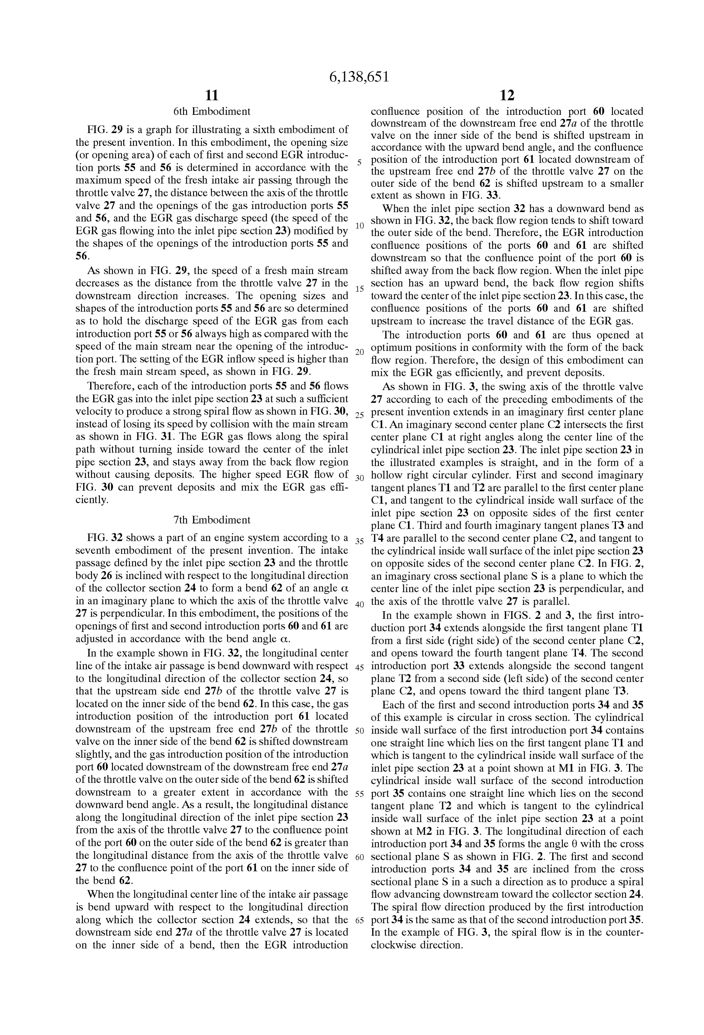
6th Embodiment confluence position of the introduction port 60 located downstream of the downstream free end 27a of the throttle
FIG. 29 is a graph for illustrating a sixth embodiment of valve on the inner side of the bend is shifted upstream in the present invention. In this embodiment, the opening Size accordance with the upward bend angle, and the confluence (or opening area) of each of first and Second EGR introduc position of the introduction port 61 located downstream of tion ports 55 and 56 is determined in accordance with the the upstream free end 27b of the throttle valve 27 on the maximum speed of the fresh intake air passing through the outer side of the bend 62 is shifted upstream to a smaller throttle valve 27, the distance between the axis of the throttle extent as shown in FIG. 33.
valve 27 and the openings of the gas introduction ports 55 When the inlet pipe section 32 has a downward bend as and 56, and the EGR gas discharge speed (the Speed of the shown in FIG. 32, the back flow region tends to shift toward EGR gas flowing into the inlet pipe section 23) modified by the outer side of the bend. Therefore, the EGR introduction the shapes of the openings of the introduction ports 55 and confluence positions of the ports 60 and 61 are shifted 56. downstream so that the confluence point of the port 60 is As shown in FIG. 29, the speed of a fresh main stream shifted away from the back flow region. When the inlet pipe decreases as the distance from the throttle valve 27 in the 15 Section has an upward bend, the back flow region shifts downstream direction increases. The opening Sizes and toward the center of the inlet pipe Section23. In this case, the shapes of the introduction ports 55 and 56 are so determined confluence positions of the ports 60 and 61 are shifted as to hold the discharge Speed of the EGR gas from each upstream to increase the travel distance of the EGR gas. introduction port 55 or 56 always high as compared with the The introduction ports 60 and 61 are thus opened at Speed of the main Stream near the opening of the introduc optimum positions in conformity with the form of the back tion port. The setting of the EGR inflow speed is higher than flow region. Therefore, the design of this embodiment can the fresh main stream speed, as shown in FIG. 29. mix the EGR gas efficiently, and prevent deposits. Therefore, each of the introduction ports 55 and 56 flows As shown in FIG. 3, the Swing axis of the throttle valve the EGR gas into the inlet pipe Section 23 at Such a Sufficient 27 according to each of the preceding embodiments of the velocity to produce a strong spiral flow as shown in FIG.30, 25 present invention extends in an imaginary first center plane instead of losing its Speed by collision with the main Stream C1. An imaginary Second center plane C2 intersects the first as shown in FIG. 31. The EGR gas flows along the spiral center plane C1 at right angles along the center line of the path without turning inside toward the center of the inlet cylindrical inlet pipe Section 23. The inlet pipe Section 23 in pipe Section 23, and stays away from the back flow region the illustrated examples is Straight, and in the form of a without causing deposits. The higher speed EGR flow of hollow right circular cylinder. First and Second imaginary FIG. 30 can prevent deposits and mix the EGR gas effi tangent planes T1 and T2 are parallel to the first center plane ciently. C1, and tangent to the cylindrical inside wall Surface of the 7th Embodiment inlet pipe Section 23 on opposite sides of the first center plane C1. Third and fourth imaginary tangent planes T3 and
FIG. 32 shows a part of an engine System according to a 35 T4 are parallel to the Second center plane C2, and tangent to seventh embodiment of the present invention. The intake the cylindrical inside wall surface of the inlet pipe section 23 passage defined by the inlet pipe Section 23 and the throttle on opposite Sides of the Second center plane C2. In FIG. 2, body 26 is inclined with respect to the longitudinal direction an imaginary croSS Sectional plane S is a plane to which the of the collector section 24 to form a bend 62 of an angle C. center line of the inlet pipe Section 23 is perpendicular, and in an imaginary plane to which the axis of the throttle valve 40 the axis of the throttle valve 27 is parallel. 27 is perpendicular. In this embodiment, the positions of the In the example shown in FIGS. 2 and 3, the first intro openings of first and Second introduction ports 60 and 61 are duction port 34 extends alongside the first tangent plane T1 adjusted in accordance with the bend angle C. from a first side (right Side) of the Second center plane C2, In the example shown in FIG. 32, the longitudinal center and opens toward the fourth tangent plane T4. The Second line of the intake air passage is bend downward with respect 45 introduction port 33 extends alongside the Second tangent to the longitudinal direction of the collector Section 24, So plane T2 from a second side (left Side) of the Second center that the upstream side end 27b of the throttle valve 27 is plane C2, and opens toward the third tangent plane T3. located on the inner Side of the bend 62. In this case, the gas Each of the first and second introduction ports 34 and 35 introduction position of the introduction port 61 located of this example is circular in croSS Section. The cylindrical downstream of the upstream free end 27b of the throttle 50 inside wall surface of the first introduction port 34 contains valve on the inner side of the bend 62 is shifted downstream one Straight line which lies on the first tangent plane T1 and Slightly, and the gas introduction position of the introduction which is tangent to the cylindrical inside wall Surface of the port 60 located downstream of the downstream free end 27a inlet pipe section 23 at a point shown at M1 in FIG. 3. The of the throttle valve on the outer side of the bend 62 is shifted cylindrical inside wall Surface of the Second introduction downstream to a greater extent in accordance with the 55 port 35 contains one Straight line which lies on the Second downward bend angle. As a result, the longitudinal distance tangent plane T2 and which is tangent to the cylindrical along the longitudinal direction of the inlet pipe Section 23 inside wall Surface of the inlet pipe Section 23 at a point from the axis of the throttle valve 27 to the confluence point shown at M2 in FIG. 3. The longitudinal direction of each of the port 60 on the outer side of the bend 62 is greater than introduction port 34 and 35 forms the angle 0 with the cross the longitudinal distance from the axis of the throttle valve 60 sectional plane S as shown in FIG. 2. The first and second 27 to the confluence point of the port 61 on the inner side of introduction ports 34 and 35 are inclined from the cross the bend 62. Sectional plane S in a Such a direction as to produce a spiral When the longitudinal center line of the intake air passage flow advancing downstream toward the collector Section 24. is bend upward with respect to the longitudinal direction The spiral flow direction produced by the first introduction along which the collector Section 24 extends, So that the 65 port 34 is the same as that of the second introduction port 35. downstream side end 27a of the throttle valve 27 is located In the example of FIG. 3, the spiral flow is in the counter on the inner side of a bend, then the EGR introduction clockwise direction.
Page 64
8th Embodiment intake air, and Sufficiently reduces the degree of nonunifor FIGS. 34 and 35 show an engine system according to an mity or irregularity in the EGR gas distribution among the eighth embodiment of the present invention. The intake and cylinders in the same manner as shown in FIG. 19. exhaust Systems for an internal combustion engine 20 shown contributes greatlyEGR
The tangential gas introduction shown in FIG. 39B in FIG. 34 are substantially identical to the systems shown as compared to the toradial the reduction of the deposit formation, introduction shown in FIG. 39A.
in FIG. 1.
In the radial arrangement of FIG. 39A, the EGR gas is
The EGR System comprises an EGR passage (external injected radially inwardly and readily brought into the recirculation passage) 231 for exhaust gas recirculation. The central back flow region through a minimum distance. By EGR passage 231 branches off from the exhaust pipe section contrast, the tangential introduction of FIG. 39B forces the 30. As shown in FIG. 35, the EGR passage 31 of this EGR gas to flow circumferentially around the central back example extends, without bifurcation (as distinct from the flow region, and the inside cylindrical Surface of the inlet EGR passage 31 of FIG. 1), to the inlet pipe section 23 of pipe Section 23 guides the circumferential Stream around the the intake manifold 21 between the throttle valve 27 and the central back flow region. The tangential EGR introduction at collector section 24. The EGR gas from the exhaust system 15 any circumferential position Significantly reduces the flows into the intake flow in the intake air passage at a amount of the deposit formation on the throttle valve 27 as confluence point located in the rear of the throttle valve 27 shown in FIG. 40.
in the downstream passage Section downstream of the The engine System according to the eighth embodiment of throttle valve 27 and upstream of the collector section 24. the present invention can make the EGR rates of the cylin The EGR passage 231 has a single EGR introduction port derS uniform even when the amount of EGR is great, and 234 having an EGR gas introduction opening which opens thereby improve the fuel consumption and exhaust perfor into the inlet pipe Section 23 at a single EGR introduction mance. Furthermore, the engine System according to the point. The EGR introduction port 234 opens from a tangen eighth embodiment can ensure the accurate control of the tial direction of a Section of the inlet pipe Section 23. In this intake air quantity by preventing deposits. embodiment, no limitation is imposed on the circumferential 25 In the eighth embodiment, it is easy to orient the EGR position of the opening of the EGR introduction port 234 introduction port 234 so that the EGR introduction port 234 along the circumferential direction of the inlet pipe Section opens downwards along the vertical direction. The tangen 23. The opening of the EGR introduction port 234 may be tial EGR introduction port 234 directed downwards can located in the rear of one bearing point for Swingably prevent accumulation of water in the EGR passage 231 by supporting the throttle valve 27 as shown in FIG. 36. condensation and aggregation of moisture in the EGR gas To meet the before-mentioned three requirements, i.e. i) to after Stoppage of the engine.
avoid the back flow region, ii) to increase a stay time of the 9th Embodiment EGR gas, iii) to mix the EGR gas into main streams of the fresh intake air from the free Swing ends of the throttle valve FIGS. 41 and 42 show an EGR system according to a 27, the EGR system according to the eighth embodiment 35 ninth embodiment of the present invention. employs the Single EGR gas introduction port 234 directed The EGR System comprises an EGR passage (external to introduce the EGR gas concentratedly along Such a recirculation passage) 231 having a single EGR introduction tangential direction as to produce a circumferential Stream port 234 opening into the inlet pipe Section 23 at a single flowing circumferentially on and along the inside cylindrical EGR introduction point as in the eighth embodiment. The Surface of the inlet pipe Section 23 around a central back 40 EGR introduction port 234 opens from the tangential direc flow region in the inlet pipe section 23, as shown in FIG. 37. tion of the circular croSS Section of the inlet pipe Section 23. The EGR gas stream thus introduced into the inlet pipe In the ninth embodiment, the EGR introduction port 234 Section 23 is pushed downstream by the fresh (upper and opens into the inlet pipe Section 23 at the Single EGR lower) main Streams flowing from the free Swing ends 27a introduction point located in the rear of the position of the and 27b of the throttle valve 27. Therefore, the EGR gas 45 upstream side free Swing end 27b of the throttle valve 27 in Stream produces a spiral flow flowing helically around the the closed position. Thus, the Single EGR introduction point central Zone, on and along the inside cylindrical Surface of is located in the region where the main flow region spreads the inlet pipe Section 23 toward the collector Section 24, as widest.
shown in FIG. 36, so that the EGR gas mixes with the fresh As shown in FIG. 41 as well as FIG. 6, the lower fresh intake air effectively. 50 main Stream coming through the gap between the upstream The spiral path prolongs the stay time of the EGR gas. The Swing end 27b of the throttle valve 27 and the inside wall of EGR gas diffuses from the circumferential annular region the intake passage tends to Spread deeper in the inward radial gradually into the central region in the process of the Spiral direction, So that the back flow region tends to recede flow advancing downstream. The EGR System according to upward as viewed in FIGS. 6 and 41. The selection of the the eighth embodiment can also mix the EGR gas with the 55 circumferential position of the Single EGR introduction fresh intake air sufficiently, and distribute the EGR gas point in the midst of this lower main Stream makes it uniformly among the cylinders with no or little Segregation. possible to shift the axial position of the single EGR The tangential introduction of the EGR gas reduces the introduction point closer to the throttle valve 27 without deposit formation on the throttle valve 27 by minimizing an increasing the amount of deposit on the throttle valve 27. amount of the EGR gas flowing directly into the central back 60 This shift of the EGR introduction point along the axial or flow region. longitudinal direction of the intake air passage upstream As shown in FIG.38, the distance L2 traveled by the EGR toward the throttle valve 27 increases the stay time and gas along the spiral flow path (corresponding to the Stay travel distance of the EGR gas. Moreover, the involvement time) to the inlet of the most upstream branch 25 is much of the fresh main stream closely behind the throttle valve 27 longer than the distance L1 of the conventional Straight path. 65 acts to Strengthen the spiral flow in the inlet pipe Section 23. The remarkable prolongation of the traveled distance of the The Single tangential EGR injection at the circumferential EGR gas helps the mixing of the EGR gas with the fresh position in the middle of the Strong main Stream according
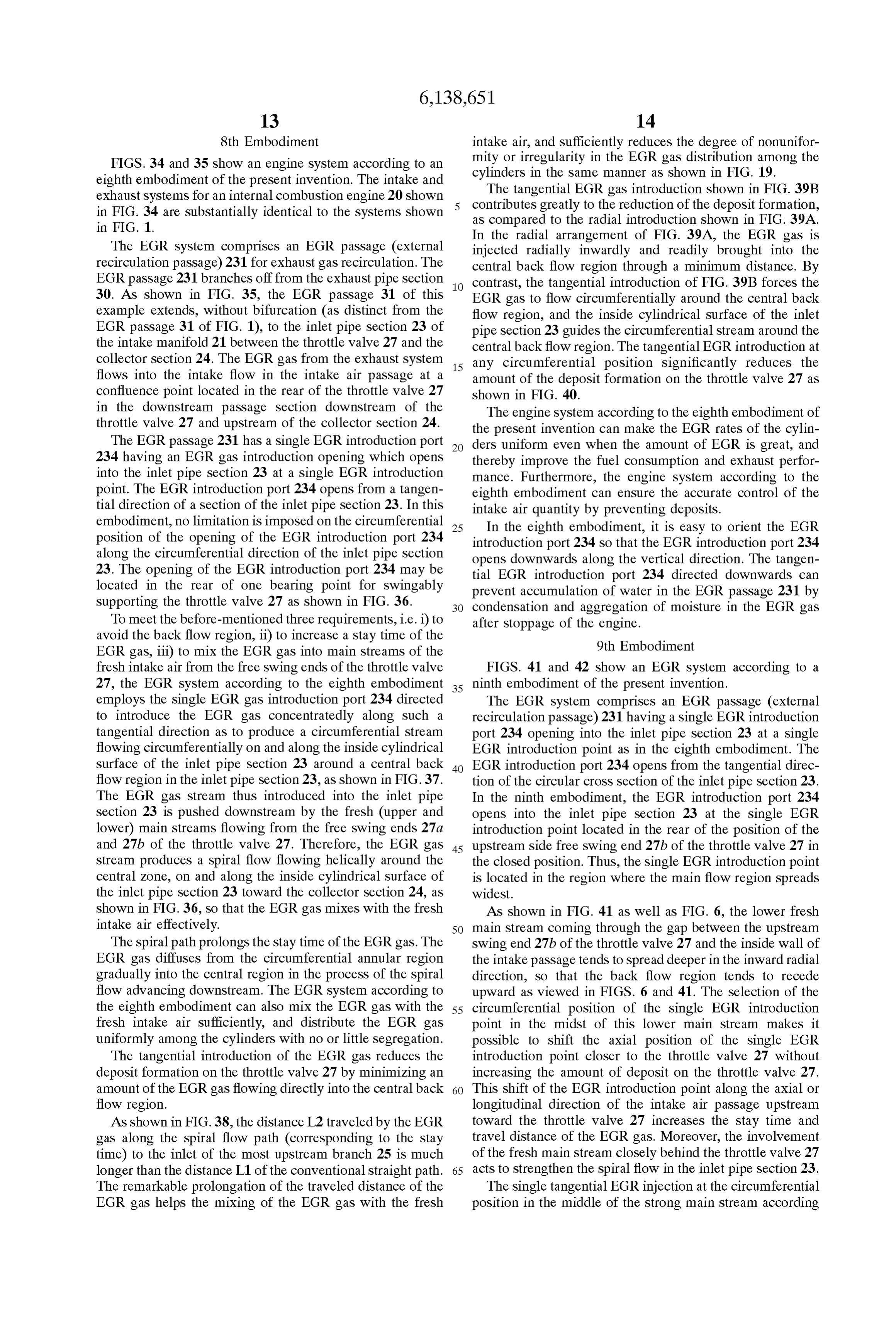
Page 65
to the ninth embodiment is effective in mixing the EGR gas 11th Embodiment with the fresh intake air for uniform EGR distribution, and FIGS. 45 and 46 show an EGR system according to an preventing passage of the EGR gas through the fresh main
Stream into the central back flow region. eleventh embodiment. A Single tangential EGR introduction port 234 comprises a guide case (or guide pipe)240 defining
FIG. 42 shows four circumferential positions M1-M4. In the EGR introduction opening. The guide case 240 in the this example, the Swing axis of the throttle valve 27 extends example shown in FIGS. 45 and 46 is cylindrical and in the imaginary first center plane C1 (as explained with projects into the inlet pipe Section 23. The guide case 240 reference to FIG. 3), and the imaginary Second center line passes through a hole formed in the inlet pipe Section 23, and C2 intersects the first center plane C1 at right angles along terminates at the open end located near an imaginary center the longitudinal center line of the intake air passage. The plane containing the longitudinal center line of the inlet pipe downstream Swing end 27a of the throttle valve 27 Swings Section 23.
on the downstream side of the axis of the throttle valve 27 and on the first side of the first center pane C1 (that is the The guide case 240 protects the EGR stream from being upper side as viewed in FIG. 42). The upstream Swing end slowed down by collision of the fresh intake air, and guides 27b of the throttle valve 27 Swings on the upstream side of 15 the fresh main Stream in a direction to promote the Spiral flow. The guide case 240 facilitates the mixing of the EGR the axis of the throttle valve 27 and on the second side of the first center pane C1 (that is the lower side as viewed in FIG. gas with the fresh intake air, and prevents the EGR gas Stream from being bent radially inwards into the central back 42). The first (or upper) circumferential position M1 is flow region by the impingement of the intake air. located just in the rear of the position of downstream Swing end 27a of the fully closed throttle valve 27 on the first 12th Embodiment (upper Side) of the first center plane C1. The Second (or lower) circumferential position M2 is located just in the rear FIG. 47 shows an EGR system according to a twelfth of the position of the upstream Swing end 27b of the fully embodiment. In this embodiment, the EGR introduction closed throttle valve 27 on the second (lower side) of the first 25 opening of a single tangential EGR introduction port 234 is center plane C1. The first and Second circumferential posi elongated in croSS Section along the fresh intake air flow tions M1 and M2 are diametrically opposite to each other on direction or the longitudinal (or axial) direction of the inlet both sides of the first center plane C1, and lie on the second pipe section 23. The cross section of the EGR port 234 is center plane C2. The third and fourth circumferential posi elliptical, and the EGR port 234 is thin in the radial tions M3 and M4 are diametrically opposite on both sides of dimension along the radial direction of the inlet pipe Section the Second center plane C2 and located on the first center 23. The EGR port 234 having the elongated section accord plane C1. The Swing axis of the throttle valve 27 extends in ing to the twelfth embodiment makes it possible to shift the parallel to the diameter between the third and fourth cir position of the EGR introduction opening upstream toward cumferential positions M3 and M4. In the example of FIG. the throttle valve 27 in a narrow main stream region. 42, the EGR introduction point is located at the second (or 35 lower) circumferential position M2 located downstream of 13th Embodiment the upstream Swing end 27b of the throttle valve 27. FIG. 48 shows an EGR system according to a thirteenth 10th Embodiment embodiment. In this embodiment, the intake air passage is inclined with respect to the longitudinal direction of the
FIGS. 43 and 44 show an EGR system according to a 40 collector Section 24 of the intake manifold 21 in an imagi tenth embodiment. In the tenth embodiment, a Single tan nary plane containing the Swing axis of the throttle valve 27. gential introduction port 234 is inclined downstream So as to In this example, the intake passage is defined by the throttle form an angle 0 with respect to an imaginary croSS Sectional body 26 and the inlet pipe section 23 of the intake manifold plane S to which the fresh intake air flow direction is 21, and a bend is formed between the inlet pipe section 23 perpendicular, in the same inclination direction as the EGR 45 and the collector Section 24. In the imaginary plane con ports 34 and 35 shown in FIG. 2. The EGR port 234 extends taining the Swing axis of the throttle valve 27, the intake from a base portion to an open end opening into the inlet passage extends along a first imaginary Straight line perpen pipe section 23. The open end of the EGR port 234 is dicular to the Swing axis of the throttle valve 27, and the remoter than the base portion from an imaginary croSS collector Section 24 extends along a Second imaginary Sectional plane containing the Swing axis of the throttle 50 Straight line interSecting the first Straight angle. valve 27. In the intake System having Such a bend, the back flow With this inclined EGR port 234 of the tenth embodiment, region tends to grow larger on the inner Side of the bend, and the EGR gas enters the main Stream Smoothly from an Smaller on the outer side of the bend as shown in FIG. 48. oblique direction with no component flowing against the Therefore, a single EGR introduction port 234 according to main stream. Therefore, the inclined EGR port 234 accord 55 the thirteenth embodiment is opened into the inlet pipe ing to the tenth embodiment can prevent the discharge Speed section 23 at an EGR introduction point located on the outer of the EGR gas from being decreased too much by collision side of the bend. The position of the EGR introduction point between the fresh main stream and the EGR stream, and is adjusted along the longitudinal direction of the inlet pipe Strengthen the Spiral flow. Section 23 in accordance with the angle of the bend. In the example of FIGS. 34 and 35, the EGR introduction 60 At the circumferential position of the EGR introduction opening of the inclined port 234 is situated at the Second point on the outer side of the bend, it is possible to shift the circumferential position M2, as in the ninth embodiment. EGR introduction point of the EGR port 234 toward the The inclined Single tangential EGR injection at the circum throttle valve 27 along the longitudinal (or axial) direction of ferential position M2 is effective in mixing the EGR gas with the inlet pipe section 23. Thus, the thirteenth embodiment the fresh intake air for uniform EGR distribution, and 65 can increase the longitudinal distance from the EGR intro advantageous in preventing passage of the EGR gas through duction point to the most upstream branch 25 of the intake the fresh main Stream into the central back flow region. manifold 21 to prolong the spiral path for the mixture of the
Page 66
EGR gas with the intake air without increasing the amount 27 for controlling the quantity of intake air Supplied to an of deposit on the throttle valve 27. engine 20. AS in the preceding embodiments, the throttle In the example shown in FIG. 48, the longitudinal (or valve 27 is swingable on a Swing axis 27c, and the throttle axial) position of the EGR introduction opening of the EGR valve 27 has a downstream side Swing end (or free end) 27a port 234 is located between the downstream end of the back which Swings to the downstream side (i.e. the right Side as flow region formed on the outer side of the bend, and the viewed in FIG. 51 toward the engine) of the Swing axis 27c downstream end of the back flow region formed on the inner and an upstream side Swing end (or free end) 27b which side of the bend when the throttle valve 27 is fully closed. Swings to the upstream side (or the left side in FIG. 51) of the Swing axis 27c.
14th Embodiment In the fifteenth embodiment, the EGR system comprises FIGS. 49 and 50 show an EGR system according to a an EGR introduction pipe 332 closed at a forward end (or fourteenth embodiment. A deflector 263 is formed on the downstream end). The EGR introduction pipe 332 is con upstream side of an EGR introduction port 234 to guide the nected with an EGR passage 331 extending from the exhaust main intake air stream along the inflow direction of the EGR 15 pipe 30. Alternatively, the EGR introduction pipe 332 may gas discharged from the EGR port 234. In the example be integral with the EGR passage 331. The EGR introduc shown in FIGS. 49 and 50, the deflector is in the form of a tion pipe 332 is inserted through a hole 334 formed in the deflecting rib 263 integrally formed in the inside wall inlet pipe Section 23, into the inlet pipe Section 23. In this example, the EGR introduction pipe 332 is a round pipe
Surface of the inlet pipe Section 23 by casting, and the EGR circular introduction port 234 comprises a guide pipe 240 as in the in croSS Section.
eleventh embodiment shown in FIGS. 45 and 46. The In this example, the EGR introduction pipe 332 extends deflecting rib 263 extends closely along the guide pipe 240 radially into the inlet pipe Section 23 along a diameter of a generally in the circumferential direction of the inlet pipe circular croSS Section of the inlet pipe Section 23 from the section 23. In the illustrated example, the deflecting rib 263 second (or lower) circumferential position M2 in the rear of extends circumferentially beyond the guide pipe 240 as 25 the upstream Swing end 27b of the throttle valve 27 to the shown in FIG. 50. Therefore, the deflecting rib 263 includes first (or upper) circumferential position M1 in the rear of the a first Section extending alongside the guide pipe 240 and a downstream Swing end 27a. The hole 334 is located at the Second Section projecting beyond the guide pipe 240 and Second (or lower) circumferential position M2 downstream protecting the EGR Stream discharged from the guide pipe of the upstream Swing end 27b of the throttle valve 27, and 240. the EGR introduction pipe 332 extends in the inlet pipe The deflecting rib 263 deflects the main intake air stream Section 23 toward the first (or upper) circumferential posi to the tangential inflow direction of the EGR gas, and tion M1 downstream of the downstream Swing end 27a. The thereby reinforces the spiral flow to facilitate the mixing of closed forward end of the EGR introduction pipe 332 closely the EGR gas with the fresh intake air and to reduce the EGR confronts the inside cylindrical Surface of the inlet pipe nonuniformity among the cylinders even at high EGR rates. 35 section 23 at the first circumferential position M1. Moreover, the deflecting rib 263 alters the shape of the back As shown in FIG. 53, the EGR introduction pipe 332 is flow region So that the back flow region becomes Smaller in formed with a first EGR introduction opening 333a opening size near the EGR introduction opening of the EGR port along a tangential direction of a circular croSS Section of the 234, and helps reduce the deposit formation by preventing inlet pipe section 23 near the forward end of the EGR the intervention of the inflow EGR gas stream into the back 40 introduction pipe 332 in the inlet pipe Section 23, and a flow region. Second EGR introduction opening 333b opening along a When the inlet pipe section 23 has no bend, the fresh tangential direction of the circular croSS Section of the inlet intake Stream grows wider and the back flow region recedes pipe section 23 near the hole 334 of the inlet pipe section 23 radially inwardly at the circumferential position M2 in the at the second (or lower) circumferential position M2. The rear of the upstream free end 27b of the throttle valve 27. 45 first and second EGR introduction openings 333a and 333b Therefore, the circumferential position M2 in the rear of the open in opposite tangential directions at the diametrically upstream free end 27b of the throttle valve 27 is advanta opposite circumferential positions M1 and M2 which are geous in general. In Some cases, however, there is need for Separated from each other at an angular distance of 180 locating the open end of the EGR port 234 at or near the around the longitudinal center line of the inlet pipe Section circumferential position M1 just in the rear of the down 50 23. The discharge directions of the first and second EGR stream free end 27a of the throttle valve 27 because of Some introduction opening 333a and 333b are parallel but directed limitation on the layout of the EGR passage 231, or because in the opposite directions in the croSS flow manner, So that the circumferential position in the rear of the upstream free the inflow EGR streams from the first and second openings end 27b necessitates an undesired arrangement in which the 333a and 33b tend to produce a circumferential flow which, EGR port 234 is opened upwards so as to form an undesired 55 in the example of FIG. 53, rotates in the clockwise direction Sump for collecting water. In Such cases, the deflecting rib around the longitudinal center line of the inlet pipe Section 263 is effective for surmounting the disadvantage of the 23. In this example, the EGR introduction pipe 332 is circumferential position in the rear of the downstream free circular in croSS Section.
end 27a, and for offering the same effects in the uniform As shown in FIGS. 54 and 55, the inflow EGR gas streams EGR distribution and deposit prevention. 60 discharged from the openings 333a and 333b are pushed
15th Embodiment downstream by the upper and lower fresh main Streams and produce a spiral flow along the inside cylindrical Surface of
FIGS. 51, 52 and 53 show an engine system according to the inlet pipe Section 23.
a fifteenth embodiment. The intake and exhaust Systems FIG. 57 illustrates influence on the inter-cylinder EGR shown in FIG. 51 are substantially identical to the systems 65 distribution and deposit formation, of a distance L of an shown in FIG. 1 and FIG. 34. As in the preceding EGR introduction point from the position of the throttle embodiments, a throttle body 26 has therein a throttle valve valve 27 as shown in FIG. 56. When the distance L is short,
Page 67
the EGR gas is readily injected into the back flow region As shown in FIG. 60, the distance Lb from the position of behind the throttle valve 27. The injection of the EGR gas the throttle shaft 27c to the position of the second EGR into the back flow region promotes the mixing with the fresh introduction opening 333b behind the upstream throttle end intake air, but increases the amount of undesired deposit 27b is smaller than the distance La of the position of the first formation. An increase in the distance L is advantageous for EGR introduction opening 333a from the position of the prevention of deposit formation. However, the degree of throttle shaft 27c. Therefore, as shown in FIG. 61, the irregularity of the cylinder to cylinder EGR distribution is longitudinal distance from the second EGR opening 333b to increased as the distance L increases. The relationship the advantage most upstream intake manifold branch 25 is increased to between the deposit formation and EGR nonuniformity the for the uniform EGR gas concentration in the manifold collector section 24. The EGR opening 333b closer requires a tradeoff therebetween as shown in FIG. 57. The to tangential EGR introduction according to the fifteenth sidetheofthrottle valve 27 is located on the second (or lower) embodiment can meet the two conflicting requirements, the of the first center shaft the throttle plane 27c (that is, the second or lower side
C1) on which the upstream Swing deposit reduction and EGR uniformization as shown in FIG. end 27b of the throttle valve 27 Swings toward the upstream 58, by producing the Spiral flow around the central region. side. The EGR opening 233a remoter from the throttle shaft The EGR introduction pipe 332 formed with the first and 15 27c is on the first (or upper) side of the throttle shaft 27c. second EGR introduction openings 333a and 333b facili This arrangement is advantageous to the deposit reduction tates the formation of the EGR introduction openings, and by prevention of interference with the back flow region thereby reduces the required amount of work (man-hours) shown in FIG. 60.
and manufacturing cost. 17th Embodiment In the example of FIGS. 52 and 53, the EGR introduction FIGS. 62 and 63 show an EGR system according to a pipe 332 extends into the inlet pipe section 23 from the Seventeenth embodiment. In this embodiment, an EGR second circumferential position M2 in the rear of the introduction pipe upstream Swing end 27b to the first circumferential position shape of a letter J332 for EGR introduction is curved in the M1 in the rear of the downstream Swing end 27a. However, tion pipe 332 enters into thein inlet as shown FIG. 62. The EGR introduc pipe section 23 from a an opposite arrangement is optional in which the EGR tangential direction tangential to a circular
croSS Section of introduction pipe 332 is inserted into the inlet pipe Section the inlet pipe Section 23, and extends circumferentially 23 from the first circumferential position M1 in the rear of along the inside cylindrical Surface of the inlet pipe Section the downstream Swing end 27a toward the Second circum 23.
ferential position M2 behind the upstream Swing end 27b. The EGR introduction pipe 332 of FIG. 62 has a forward In the example of FIGS. 51-53, the opening directions of pipe end which opens in a tangential direction and defines a the first and second EGR introduction openings 333a and first EGR introduction opening 333a. The EGR introduction 333b are not inclined with respect to an imaginary croSS pipe 332 is formed with a second EGR introduction opening Sectional plane of the inlet pipe Section 23, and both open 233b opening in a tangential direction. The first and second ings 333a and 333b open in the opposite tangential direc 35 EGR introduction openings 233a and 233b open in parallel tions extending in the imaginary croSS Sectional plane. but opposite tangential directions (in the cross flow manner) at diagonally opposite circumferential positions.
16th Embodiment In the example of FIGS. 62 and 63, the second EGR opening 333b is formed in a cylindrical circumferential wall
FIGS. 59, 60 and 61 show an EGR system according to a of the EGR introduction pipe 332 at the second (lower) sixteenth embodiment. 40 circumferential position M2 in the rear of the upstream The EGR system according to the 16th embodiment throttle end 27b. The first EGR opening 333a defined by the comprises an EGR introduction pipe 332 which is inserted forward end of the EGR introduction pipe 332 is located at into the inlet pipe section 23 through a hole 334 of the inlet the first (upper) circumferential position M1 in the rear of pipe Section 23, closed at a forward end (or downstream end) the downstream throttle end 27a. The EGR introduction pipe and formed with first and Second EGR introduction openings 45 332 has a Straight Segment extending in one tangential 333a and 333b opening in the opposite tangential directions direction through a hole formed in the inlet pipe Section 23 at the radially spaced, diagonally opposite circumferential and a Semicircular Segment having the first and Second EGR positions M1 and M2 as in the fifteenth embodiment. openings 333a and 33b at both ends.
According to the 16th embodiment, the EGR introduction The thus-arranged EGR introduction openings 333a and pipe 332 is inclined downstream So as to Space the first and 50 333b inject the EGR gas so as to form a circumferential flow second EGR introduction openings 333a and 333b apart in around the central back flow region in the counterclockwise the longitudinal or axial direction of the inlet pipe Section 23 direction as viewed in FIG. 62, and the thus-injected EGR as well as in the radial direction in order to enhance the gas and the fresh main Streams around the back flow region improvement of the EGR characteristic by the spiral flow. produce a spiral flow advancing downward. As shown in FIG. 59, the EGR introduction pipe 332 is 55 When the throttle valve 27 is fully open, the flow velocity inclined with respect to a croSS Sectional plane of the inlet is higher in the central region and lower in the annular pipe Section 23 So as to form an angle (p. The EGR intro circumferential region near the inside cylindrical wall Sur duction pipe 332 extends obliquely in the inlet pipe Section face of the intake air passage, as shown in FIG. 64. The 23 along an inclined Straight line from the Second (or lower) curved EGR introduction pipe 332 of FIGS. 62 and 63 circumferential position M2 in the rear of the upstream 60 extends in the lower Speed circumferential region. The Swing end 27b of the throttle valve 27 toward the first thus-arranged curved EGR introduction pipe 332 functions circumferential position M1 in the rear of the downstream to reduce the flow resistance of the intake air and to improve Swing end 27a. Therefore, the first EGR introduction open the output torque in a high load engine operation. ing 333a at the first (upper) circumferential position M1 is 18th Embodiment located downstream of the second EGR opening 333b at the 65
Second (lower) circumferential position M2 along the lon FIGS. 65 and 66 shows an EGR system according to an gitudinal direction of the inlet pipe Section 23. eighteenth embodiment. An EGR introduction pipe 332 for
Page 68
EGR gas introduction is curved and extends along the 20th Embodiment circumferential direction as in the 17th embodiment.
However, the EGR introduction pipe 332 shown in FIG. 65 according FIGS. 69 and 70 shows an EGR introduction pipe 332 extends circumferentially only through about 90. The EGR pipe to a twentieth embodiment. The EGR introduction introduction pipe 332 has a Straight Segment extending 332 is formed in a streamline shape to reduce the tangentially through a hole formed in the inlet pipe Section resistanceshape to the fluid flow in the intake passage. The croSS 23 and an arc Segment extending circumferentially along the sectional gated along the of the EGR introduction pipe 332 is elon longitudinal direction of the intake passage, inside cylinder wall surface of the inlet pipe section 23. The as shown in FIG. 69. The cross sectional shape of the EGR EGR introduction pipe 332 has an open forward pipe end defining a first EGR introduction opening 333a and a second 1O introduction pipe 332 is tapered and sharpened toward each EGR introduction opening 333b formed at a connecting of upstream and downstream ends.
position between the Straight Segment and the arc Segment. In the other respects, the EGR introduction pipe 332 The angular distance between the first and second EGR shown in FIGS. 69 and 70 is substantially identical to the openings 333a and 333b is about 90 around the center line EGR introduction pipe 332 shown in FIGS. 51, 52 and 53. of the inlet pipe section 23. 15 It is optional to employ an EGR introduction pipe 332 In the example of FIGS. 65 and 66, the first EGR having a streamlined croSS Section in any of the 15th through 19th embodiments.
introduction opening 333a defined by the open end of the
EGR introduction pipe 332 is located substantially on the 21st Embodiment first (or horizontal) center plane C1 containing the axis of the throttle valve and the longitudinal center line of the intake FIGS. 71 and 72 show an EGR system according to a passage. The second EGR introduction opening 333b is twenty-first embodiment.
located at the Second (lower) circumferential position down In this embodiment, an EGR passage 431 bifurcates into stream of the position of the upstream Swing end 27b of the a first branch passage having a first EGR introduction port throttle valve 27. The second EGR introduction opening 409 and a second branch passage having a second EGR 333b opens in a rightward tangential direction as viewed in 25 introduction port 410. The first EGR introduction port 409 FIG. 65 whereas the first EGR introduction opening 333a opens tangentially into the inlet pipe Section 23 at an opens in an upward tangential direction as viewed in FIG. upstream EGR introduction point downstream of the throttle 65. In the example of FIGS. 65 and 66, the opening area of valve 27 and upstream of the manifold collector section 24. the first EGR introduction opening 333a at the circumfer The second EGR introduction port 410 opens toward the ential position downstream of one shaft end of the throttle center of the collector Section 24 at a downstream EGR valve shaft 27.c is smaller than the opening area of the introduction point downstream of the upstream EGR intro second EGR introduction opening 333b. The smaller EGR duction point. In this example, the downstream EGR intro introduction opening 333a increases the injection speed of duction port 410 opens toward a central region of a upstream the EGR gas discharged in the tangential direction and end portion of the collector Section 24 along a direction to thereby reduces the amount of EGR gas injected into the 35 produce an EGR stream toward the downstream end of the central back flow region. The shortened EGR introduction collector Section 24.
pipe 332 of FIGS. 65 and 66 is advantageous to the flow The tangentially extending first (upstream) EGR intro resistance in the intake passage. duction port 409 produces a spiral flow in the same manner
as in the preceding embodiments to improve the homoge neous mixing and the deposit reduction. This spiral flow
FIGS. 67 and 68 show an EGR introduction pipe 332 for promotes the diffusion of the EGR gas introduced from the EGR introduction according to a nineteenth embodiment. second EGR introduction port 410.
The EGR introduction pipe 332 of the 19th embodiment is The EGR gas introduced from the first EGR port 409 inserted diametrically into the inlet pipe Section 23 and 45 tends to flow into the branches 25 in the upstream part and formed with first and second EGR introduction openings the EGR gas introduced from the second (downstream) EGR 333a and 333b like the EGR introduction pipe 332 shown in port 410 tends to flow into the branches 25 in the down FIGS. 51-55 according to the 15th embodiment. According stream part. The separation of the first and second EGR to the 19th embodiment, each of the first and second EGR introduction points along the longitudinal direction of the introduction openings 333a and 333b opens in a direction 50 intake air passage helps reduce the nonuniformity in the inclined downstream So as to form an angle 0 with respect EGR distribution among the cylinders. The uniform EGR to a croSS Sectional plane of the inlet pipe Section 23 as distribution is advantageous to the Stability of the engine, the shown in FIG. 68. fuel economy and emission control. According to the 19th embodiment, the EGR introduction The downstream EGR introduction port 410 remote from pipe 332 has the first and second EGR introduction openings 55 the throttle valve 27 is exempt from the influence of the back 333a and 333b opened in the EGR introduction pipe 332 flow region and hence advantageous to the deposit reduc obliquely So as to facilitate a spiral flow. This arrangement tion.
can reduce the deposit formation by reducing the possibility of back ward flow of the EGR gas toward the throttle valve 22nd Embodiment 27 and promote the mixing of the EGR gas with the fresh 60 FIGS. 73 and 74 show an EGR system according to a intake airby increasing the Spiral flow and enabling the shift twenty-second embodiment. The EGR system of this of the EGR introduction point upstream toward the throttle embodiment has upstream and downstream EGR introduc valve 27. tion ports 409 and 410 as in the 21st embodiment. The In the Same manner, it is optional to incline the opening upstream EGR introduction port 409 according to the 22nd direction of at least one EGR introduction opening in each 65 embodiment has a guide pipe 411 projecting into the inlet of the 15th through 18th embodiments to achieve the same pipe section 23. In the example shown in FIGS. 73 and 74, effect. the guide pipe 411 is inclined downstream So as to form an
Page 69
angle 0 with a croSS Sectional plane of the inlet pipe Section has upstream and downstream EGR introduction ports 409 23 as shown in FIG. 74. and 410 as in the 21st through 26th embodiments. In the 27th 23rd Embodiment embodiment, as shown in FIG. 81, the opening area of the upstream EGR introduction port 409 disposed closely
FIGS. 75 and 76 show an EGR system according to a behind the throttle valve 27 is smaller than the opening area twenty-third embodiment. The EGR system of this embodi of the downstream EGR introduction port 410. The upstream ment has upstream and downstream EGR introduction ports EGR introduction port 409 having the smaller EGR intro 409 and 410 as in the 21st and 22nd embodiments. The duction opening functions to reduce the deposit formation upstream EGR introduction port 409 according to the 23rd on the throttle valve 27.
embodiment is opened at one of the diagonally opposite 28th Embodiment circumferential positions M1 and M2 on the Second imagi nary center plane C2 to which the shaft 27c of the throttle FIGS. 82-84 show an engine system according to a valve 27 is perpendicular. twenty-eighth embodiment. The intake and exhaust Systems 24th Embodiment are Substantially identical to the Systems of the preceding 15 embodiments. The EGR system shown in FIG. 82 has an
FIGS. 77 and 78 show an EGR system according to a EGR passage 531 bifurcates into first and second branch twenty-fourth embodiment. The EGR system of this passages 532 and 533 as shown in FIG. 84. The first and embodiment has upstream and downstream EGR introduc second branch passages 532 and 533 have, respectively, first tion ports 409 and 410 as in the 21st, 22nd and 23rd and second EGR introduction ports 534 and 535 which embodiments. The upstream EGR introduction port 409 extend in parallel but opposite tangential directions and open according to the 24th embodiment is opened at the Second into the inlet pipe Section 23 at diametrically opposite (lower) circumferential position M2 downstream of the circumferential positions in the same rotational direction position of the upstream Swing end 27b of the fully closed (the counterclockwise direction as viewed in FIG. 84) throttle valve 27. around the longitudinal center line of the inlet pipe Section 25th Embodiment 25 23. The EGR introduction opening of the first EGR port 534
FIG. 79 shows show an EGR system according to a isdownstream located downstream of the circumferential position of the Swing end 27a of the throttle valve 27, and the twenty-fifth embodiment. The EGR system of this embodi EGR introduction ment has upstream and downstream EGR introduction ports located downstreamopening of the of the second EGR port 535 is circumferential position of the 409 and 410 as in the 21st through 24th embodiments. As upstream Swing end 27b. Each of the first and second EGR shown in FIG. 79, the upstream EGR introduction port 409 ports 534 and 535 is inclined downstream of the 25th embodiment has an EGR introduction opening predetermined angle (lead angle) with a so as to form a cross Sectional which is elongated along the longitudinal direction of the plane of the inlet pipe Section 23.
intake passage. The EGR introduction opening defined by In the 28th embodiment, the longitudinal (or axial) dis the open end of the upstream EGR introduction port 409 is 35 tance Lb from the position of the Swing axis of the throttle located at a circumferential position downstream of one valve 27
Swing end of the throttle valve 27. The elongated EGR the secondto EGR the position of the EGR introduction opening of port 535 in the rear of the upstream Swing introduction opening reduces the undesired influence of the end 27b of the throttle valve 27 is smaller than the longi back flow region and enables the reduction of the distance tudinal from the throttle valve 27 to the EGR introduction point. 40 axis of the throttle valve La27from (or axial) distance the position of the Swing to the position of the EGR 26th Embodiment introduction opening of the first EGR port 534 in the rear of FIG. 80 shows an EGR system according to a twenty the downstream Swing end 27a of the throttle valve 27, sixth embodiment. The EGR system of this embodiment has along the longitudinal (or axial) direction of the inlet pipe upstream and downstream EGR introduction ports 409 and 45 Section 23, as shown in FIG. 83.
410 as in the 21st through 25th embodiments. In the 26th The first and second EGR port 534 and 535 produce a embodiment, as shown in FIG. 80, both the upstream and spiral flow as shown in FIG. 85. The reduction of the downstream EGR introduction ports 409 and 410 have a distance Lb on the same Side as the upstream Swing end 27b guide pipe 411. In the example of FIG. 80, the guide pipe is effective for uniform EGR distribution, and possible 411 of the upstream port 409 projects in the inlet pipe section without increasing the interference with the back flow region 23, to an upstream EGR introduction point near the Second 50 as shown in FIG. 86 specifically when there is no bend (vertical) center plane C2. The guide pipe 411 of the between the inlet pipe section 23 and the manifold collector downstream port 410 extends approximately in a longitudi Section 24.
nal direction of the manifold collector section 24 toward the 29th Embodiment downstream end of the collector Section 24, and projects into 55 the downstream end portion of the inlet pipe Section 23, to FIG. 87 shows an EGR system according to a twenty a downstream EGR introduction point located near the ninth embodiment. The EGR system of FIG. 87 has first and central region of the upstream end portion of the collector second EGR introduction ports 534 and 535 similar to the section 24. In the example of FIG. 80, the guide pipe 411 of first and Second EGR introduction ports according to the the downstream port 410 opens at the downstream EGR 60 28th embodiment. Unlike the 28th embodiment, the down introduction point closer to, and slightly upstream of, the Stream inclination angels (or lead angles) of the first and upstream end of the collector Section 24, and facilitates the second EGR introduction ports 534 and 535 according to the flow of the EGR gas from the downstream port 410 into the 29th embodiment are not equal. The downstream inclination branches 25 in the upstream part. angle (or lead angle) 0b of the second EGR port 535 located 27th Embodiment downstream of the upstream Swing end 27b of the throttle 65 valve 27 is smaller than the downstream inclination angle 0a
FIG. 81 shows an EGR system according to a twenty of the first EGR port 535 downstream of the downstream seventh embodiment. The EGR system of this embodiment Swing end 27a of the throttle valve 27.
Page 70
Therefore, the second EGR port 535 can produce a spiral Swing axis of the throttle valve 27 is perpendicular. In such flow having a smaller pitch (so that the spiral flow advances an intake System, a strong fresh main Stream flows from the through a shorter distance along the longitudinal or axial inner side of the bend toward the outer side of the bend, so direction of the intake passage, per revolution of the spiral) that the back flow region grows larger on the outer Side of and thereby increase the travel distance of the EGR gas the bend and becomes Smaller on the inner side of the bend along the Spiral path for uniform EGR distribution among as shown in FIG. 91.
the cylinders. After the travel through an angular distance of In the example shown in FIG. 91, therefore, the throttle about 180 along the inside cylindrical Surface of the inlet valve 27 is so arranged that the downstream Swing end 27a pipe section 23, part of the spiral flow from the EGR port is located on the Outer Side and the upstream Swing end 27b 535 may traverse the back flow region. However, this partial is located on the inner side of the bend, instead of the traverse of the Spiral flow is not So disadvantage to the opposite arrangement shown in FIG. 90 for comparison. deposit reduction because the travel half around the central Therefore, the Strong main Stream from the upstream Swing Zone can bring a considerable progreSS in mixing the EGR end 27b on the inner side flows toward the outer side of the gas with the fresh intake air, and prevent direct influx of bend, and thereby decreases the back flow region on the thick EGR gas into the back flow region. 15 inner side behind the upstream Swing end 27b. On the inner In the example shown in FIG. 87, the first and second side of the bend where the back flow region is reduced, the EGR ports 534 and 535 are differentiated in both the position of the EGR introduction opening of the Second downstream inclination angle 0 and the longitudinal dis EGR port 535 behind the upstream Swing end 27a of the tance L from the Swing axis of the throttle valve 27. throttle valve 27 is shifted largely upstream toward the throttle valve 27 to decrease the longitudinal distance L from 30th Embodiment the throttle valve 27 to the EGR introduction point and to FIG. 89 shows an EGR system according to a thirtieth increase the travel distance of the EGR gas. In the compara embodiment. In this embodiment, there is a bend between tive example shown in FIG. 90, by contrast, it is difficult to the intake passage and the manifold collector Section 24. AS 25 shift the position of the EGR opening of the EGR port 535 shown in FIG. 89, the longitudinal direction of the manifold behind the upstream Swing end 27b of the throttle valve 27, collector Section 24 is inclined with respect to the longitu upstream toward the throttle valve 27 without increasing the dinal direction of the intake passage defined by the manifold of the upstream the deposit because back flow region grows larger in the rear
Swing end 27b.
inlet pipe Section 23 and the throttle body 26 in an imaginary plane containing the Swing axis of the throttle valve 27. In 32nd Embodiment Such an intake System, the main Stream is Stronger on the outer Side than on the inner Side of the bend, and hence the FIGS. 92-96 show an engine system according to a back flow region becomes larger on the inner Side and thirty-Second embodiment. The engine System shown in Smaller on the outer side, as shown in FIG. 88. FIG. 92 is substantially identical to the engine system shown In the example shown in FIG. 89, therefore, the EGR 35 in FIG. 1 except for the inclination angles of the EGR introduction opening of the first EGR introduction port 534 introduction ports. An EGR passage 631 bifurcates into a downstream of the downstream Swing end 27a of the throttle first branch passage 632 having a first EGR introduction port valve 27 is located on and toward the inner side of the bend, 634 and a second branch passages 633 having a second EGR and the EGR introduction opening of the second EGR introduction port 635. Each of the first and second EGR introduction port 535 downstream of the upstream Swing 40 introduction ports 634 and 635 has an EGR introduction end 27b of the throttle valve 27 is located on and toward the opening formed at the port end, and the first and Second EGR outer Side of the bend, by contrast to the opposite arrange introduction ports 634 and 635 are arranged, as shown in ment shown in FIG. 88 for comparison. In the example FIG. 94, in the same manner as FIG. 3. However, as shown shown in FIG. 89, the position of the first EGR opening of in FIG. 93 (by contrast to FIG. 2), each of first and second the first EGR port 534 remains unchanged on the inner side 45 EGR introduction ports 634 and 635 is not inclined, but where the back flow region is more influential. On the outer extends in an imaginary Sectional plane to which the lon side of the bend where the back flow region is small, the gitudinal center line of the inlet pipe Section 23 is perpen position of the EGR introduction opening of the Second dicular.
EGR port 535 behind the upstream Swing end 27b of the The EGR gas introduced into the inlet pipe section 23 throttle valve 27 is shifted largely upstream toward the 50 from each of the non-inclined EGR introduction ports 634 throttle valve 27 to increase the travel distance of the EGR and 635 has only a Velocity component along the tangential gas. In the comparative example shown in FIG. 88, by direction tangent to the circular croSS Section of the inlet pipe contrast, it is difficult to shift the position of the EGR section 23. However, in the inlet pipe section 23, the EGR opening of the EGR port 534' behind the downstream Swing gas is pushed downstream by the fresh main Stream (and end 27a of the throttle valve 27, upstream toward the throttle 55 thereby provided with a Velocity component along the Valve 27 without increasing the deposit because the back downstream direction of the fresh main stream). As a result, flow region is dominant in the rear of the downstream Swing the EGR gas discharged from each EGR introduction port end 27a as shown in FIG. 86. 634 or 635 produces a spiral flow as shown in FIGS. 95 and
31st Embodiment 60 The first and Second, non-inclined, tangential EGR intro
FIG.91 shows an EGR system according to a thirty-first duction ports 634 and 635 can improve the EGR distribution embodiment. In this embodiment, there is a bend between and reduce deposit formation. Moreover, the non-inclined the intake passage and the manifold collector Section 24, and design facilitates manufacturing operations Such as machin the longitudinal direction of the manifold collector Section ing operation and assemblage. The non-inclined ports 634 24 is inclined with respect to the longitudinal direction of the 65 and 635 can be formed only by processing along the intake passage defined by the manifold inlet pipe Section 23 longitudinal or axial direction of the inlet pipe Section 23 and and the throttle body 26 in an imaginary plane to which the the normal direction perpendicular to the longitudinal direc
Page 71
tion of the inlet pipe Section 23. The non-inclined ports can As shown in FIG. 103, the speed of a fresh main stream be formed by a two-axis (or two dimensional) machine, for decreases as the distance from the throttle valve 27 in the example. downstream direction increases. The opening Sizes and 33rd Embodiment shapes of the first and Second EGR introduction ports are So determined as to hold the discharge Speed of the EGR gas
FIGS. 97-99 show an EGR system according to a thirty from each introduction port always Sufficiently higher than third embodiment. The EGR system of this embodiment the Speed of the main Stream near the opening of the comprises first and Second non-inclined EGR introduction introduction port. The setting of the EGR inflow speed is ports 634 and 635 as in the 32nd embodiment. Each of the 1O 103. higher than the fresh main Stream Speed, as shown in FIG. first and second non-inclined EGR ports 634 and 635 comprises a guide case 640 projecting into the inlet pipe Therefore, each of the introduction ports discharges the Section 23 and defining the EGR introduction opening as in EGR gas into the inlet pipe Section 23 at Such a Sufficient the second embodiment shown in FIGS. 22-24. velocity to produce a strong spiral flow as shown in FIG. 30, instead of losing its Speed by collision with the main Stream 34th Embodiment 15 as shown in FIG. 31. The EGR gas flows along the spiral
FIGS. 100 and 101 show an EGR system according to a path without turning inside toward the central region of the thirty-fourth embodiment. The EGR system of this embodi inlet pipe Section 23, and Stays away from the back flow ment comprises first and Second non-inclined EGR intro region can without causing deposits. The higher Speed EGR flow prevent deposits and mix the EGR gas efficiently.
duction ports 645 and 646 as in the 32nd and 33rd embodiments, and the croSS Sectional shape of each non 37th Embodiment inclined EGR introduction port 645 or 646 is elongated along the longitudinal direction of the inlet pipe Section 23 FIG. 104 shows a part of an engine System according to as in the third embodiment shown in FIGS. 25 and 26. In the a thirty-seventh embodiment of the present invention. The example shown in FIGS. 100 and 101, the opening size of 25 EGR system of this embodiment comprises first and second the EGR introduction opening formed at the end of the non-inclined tangential gas introduction ports 660 and 661 second EGR introduction port 646 in the rear of the as in the 32nd through 36th embodiments. The intake upstream Swing end 27b of the throttle valve 27 is greater passage defined by the inlet pipe Section 23 and the throttle than the opening Size of the EGR introduction opening of the body 26 is inclined with respect to the longitudinal direction first EGR introduction port 645 in the rear of the down of the collector section 24 to form a bend 62 of an angle C. stream Swing end 27a of the throttle valve 27, as in the in an imaginary plane to which the axis of the throttle valve example of FIGS. 25 and 26. 27 is perpendicular, as in the example shown in FIG. 32. In the 37th embodiment, the positions of the EGR introduction 35th Embodiment openings of the first and second non-inclined tangential FIG. 102 shows a combination of EGR system and intake 35 EGR introduction ports 660 and 661 are adjusted in accor System according to a thirty-fifth embodiment. The System dance with the bend angle C. Substantially in the same shown in FIG. 102 comprises first and second non-inclined manner as the seventh embodiment shown in FIG. 32. tangential gas introduction ports 650 and 651 as in the 32nd endIn27b the example shown in FIG. 104, the upstream Swing of the throttle valve 27 is located on the inner side through 34th embodiments. In the 35th embodiment, moreover, the EGR gas is introduced from the Second 40 of the bend 62, and the longitudinal distance of the EGR introduction port 651 having the EGR introduction opening introduction opening of the Second non-inclined EGR intro duction port 661 from the Swing axis of the throttle valve is located just in the rear of the upstream Swing end 27b of the Smaller throttle valve 27 whereas an auxiliary air is introduced from than that of the first non-inclined EGR introduction the first introduction port 650 having a gas introduction port 660.
opening located just in the rear of the downstream Swing end 45 FIGS. 1-33 and the explanations of the first through 27a of the throttle valve 27, as in the fourth embodiment Seventh embodiments remain Substantially unchanged from shown in FIG. 27. The non-inclined EGR introduction port the original U.S. application Ser. No. 09/076,489, now 651 is connected with the exhaust system, while the non abandoned. An original claim 43 of this CIP Application is inclined auxiliary air introduction port 650 is connected with identical to the original claim 1 of the parent application Ser. an upstream portion of the intake System located near an air 50 No. 09/076,489, now abandoned.
cleaner on the upstream side of the throttle valve 27. The EGR introduction port according to the first through 36th Embodiment
Seventh embodiments is inclined with respect to a croSS
Sectional plane of the intake passage. However, it is possible
FIG. 103 is a graph for illustrating a thirty-sixth embodi to employ at least one non-inclined EGR introduction port ment. The EGR system of this embodiment comprises first 55 (or opening) as in Some other embodiments, (specifically in and Second non-inclined tangential gas introduction ports as the thirty-second through thirty-seventh embodiments in the 32nd through 35th embodiments. In this embodiment, shown in FIGS. 92-104). Moreover, the EGR system may the first and Second ports are EGR introduction ports, and be arranged to include only one EGR introduction port (or the opening size (or opening area) of each of first and Second opening) as specifically disclosed in the eighth through non-inclined tangential EGR introduction ports is deter 60 fourteenth embodiments of FIGS. 34-50. What is claimed is:
mined in accordance with the maximum speed of the fresh intake air passing through the throttle Valve 27, the distance 1. An exhaust gas recirculation System for an engine, between the axis of the throttle valve 27 and the opening of comprising:
the gas introduction port, and the EGR gas discharge Speed an exhaust System for carrying exhaust gas away from the (the speed of the EGR gas flowing into the inlet pipe Section 65 engine;
23) modified by the shape of the opening of the introduction an intake System comprising a pipe arrangement for port, as in the Sixth embodiment. distributing intake air to cylinders of the engine, the
Page 72
pipe arrangement comprising a collector Section, a 7. The engine System as claimed in claim 4 wherein the plurality of branches leading from the collector Section, EGR introduction opening opens in the EGR introducing respectively, to the cylinders of the engine, and an direction which is tangential to the curved inside wall intake passage Section for introducing the intake air Surface of the downstream intake passage Section. into the collector Section, the intake System further 8. The engine system as claimed in claim 7 wherein the comprising a throttle valve disposed in the intake curved inside wall Surface of the downstream passage Sec passage Section at an intermediate position dividing the tion is a cylindrical inside surface and the EGR introduction intake passage Section into an upstream intake passage opening opens in the EGR introducing direction tangential SubSection on an upstream Side of the throttle valve and to the cylindrical inside Surface of the downstream intake a downstream intake passage SubSection extending 1O passage Section; and wherein the downstream intake passage from the throttle valve to the collector section; and Section has a circular croSS Section, and the EGR introduc an EGR System for returning part of the exhaust gas as tion opening opens along the EGR introducing direction EGR gas from the exhaust System into the downstream tangential to the circular croSS Section of the downstream passage SubSection of the intake System, the EGR intake passage Section.
System comprising an EGR gas introduction port hav 15 9. The engine system as claimed in claim 7 wherein the ing an EGR gas introduction opening for directing an EGR introducing direction is parallel to an imaginary croSS inflow EGR gas Stream into the downstream passage Sectional plane of the downstream intake passage Section. 10. The engine system as claimed in claim 7 wherein an
SubSection, the EGR gas introduction opening being opening area of the EGR introduction opening is determined located downstream of a first free end of the throttle
Valve in a closed position, the EGR gas introduction Stream passingwith in accordance a maximum speed of a fresh intake air through the throttle valve, a distance from a port extending along a tangential direction tangential to Swing axis of the a curved inside wall Surface of the downstream passage opening and a speedthrottle valve to the EGR introduction of an EGR gas inflow Stream modified
SubSection. by an opening shape of the EGR introduction opening. 2. The exhaust gas recirculation System as claimed in 11. The engine system as claimed in claim 7 wherein the claim 1 wherein an inflow direction of the EGR gas intro 25 EGR introducing direction is an inclined direction which is duction port is inclined downstream So as to form a prede inclined with respect to an imaginary croSS Sectional plane termined angle with respect to a direction of a fresh intake of the downstream intake passage Section and which is air Stream in the downstream passage SubSection.
3. The exhaust gas recirculation System as claimed in intermediate between a non-inclined direction parallel to the imaginary croSS Sectional plane of the downstream intake claim 1 wherein an inflow direction of the EGR gas intro passage Section and a downstream longitudinal direction of duction port extends in an imaginary croSS Sectional plane of the downstream intake passage Section. the downstream passage SubSection. 12. The engine System as claimed in claim 11 wherein the 4. An engine System comprising: EGR introducing direction is a direction tangent to an an engine; imaginary helix around the longitudinal center line of the an exhaust System for carrying exhaust gas away from the 35 downstream intake passage Section, an inclination angle engine; between the EGR introducing direction and the imaginary an intake System for Supplying intake air to the engine, the croSS Sectional plane of the downstream intake passage intake System comprising a throttle valve disposed in Section is equal to a lead angle of the helix, and a lead of the an intake passage which comprises an upstream intake helix is Smaller than a distance between the EGR introduc passage Section on an upstream Side of the throttle 40 tion point and an inlet of any of the branches of the intake Valve and a downstream intake passage Section on a pipe System.
downstream side of the throttle valve; and 13. The engine system as claimed in claim 7 wherein the an EGR System for returning part of the exhaust gas as EGR System comprises an EGR introduction port extending EGR gas from the exhaust System into the downstream in the EGR introducing direction, and having an open end intake passage Section of the intake System, the EGR 45 defining the EGR introduction opening. System comprising an EGR introduction opening which 14. The engine system as claimed in claim 13 wherein the opens into the downstream intake passage Section in a EGR introduction port comprises a guide case projecting predetermined EGR introducing direction to direct an along the EGR introducing direction into the downstream inflow EGR gas Stream circumferentially along a intake passage Section, and defining the open end of the curved inside wall Surface of the downstream passage 50 EGR introduction port.
Section around a central region of the downstream 15. The engine system as claimed in claim 7 wherein the intake passage Section. EGR System comprises an EGR introduction pipe defining 5. The engine System as claimed in claim 4 wherein the the EGR introduction opening for introducing the EGR gas EGR introduction opening faces in the EGR introducing into the downstream intake passage Section, the EGR intro direction which extends through a circumferential annular 55 duction pipe projects into the downstream intake passage region Surrounding the central region in the downstream Section through a hole formed in a circumferential wall of intake passage Section without interSecting the central region the downstream intake passage Section, and the EGR intro which is a region in which a back flow region extends behind duction pipe comprises a base side pipe Section formed with the throttle valve when the throttle valve is fully closed, and the EGR introducing opening and a tip side pipe Section the EGR introduction opening is located, longitudinally 60 which defines a tip end of the EGR introduction pipe and along a longitudinal direction of the intake passage, between which is formed with another EGR introduction opening. the throttle valve and a downstream end of the back flow 16. The engine system as claimed in claim 15 wherein the region formed on the downstream side of the throttle valve EGR introduction opening of the tip side pipe Section is when the throttle valve is fully closed. opened in the tip end of the EGR introduction pipe, and the 6. The engine System as claimed in claim 4 wherein the 65 EGR introduction pipe extends circumferentially in the EGR introduction opening is elongated along a longitudinal downstream intake passage Section along the curved inside direction of the downstream intake passage Section. wall Surface of the downstream intake passage Section.
Page 73
17. The engine system as claimed in claim 15 wherein at is greater than a croSS Sectional area of the first EGR least one of the EGR introduction openings is opened in an introduction opening.
inclined direction tangential to an imaginary circular helix 25. The engine System as claimed in claim 23 wherein a around a longitudinal center line of the downstream intake distance of the second EGR opening from the throttle valve passage Section to produce a spiral flow advancing down is smaller than a distance of the first EGR opening from the Stream in the downstream passage Section. throttle valve.
18. The engine system as claimed in claim 15 wherein the 26. The engine System as claimed in claim 23 wherein EGR introduction pipe has a Streamlined outside contour to each of the first and Second EGR introducing directions is reduce a resistance to a fluid flow in the downstream intake inclined toward a downstream Side to produce a spiral flow passage Section. advancing downstream in the downstream passage Section, 19. The engine system as claimed in claim 15 wherein the and an inclination angle formed between the Second EGR EGR introduction openings formed in the base side pipe introducing direction and a croSS Sectional plane of the Section and tip side pipe Section of the EGR introduction downstream passage Section is Smaller than an inclination pipe are located at diametrically opposite positions around a angle formed between the first EGR introducing direction longitudinal center line of the downstream intake passage 15 and a croSS Sectional plane of the downstream passage Section, and directed in parallel but opposite directions. Section.
20. The engine system as claimed in claim 19 wherein the 27. The engine system as claimed in claim 23 wherein the EGR introduction opening formed in the tip side pipe EGR system comprises an EGR introduction pipe which is Section is opened to a first EGR introduction point located formed with the first and second EGR introduction openings behind a downstream Swing end of the throttle valve which and which extends, inside the downstream passage Section, Swings toward a downstream Side of a Swing axis of the between a position of the first EGR introduction opening and throttle valve, and the EGR introduction opening formed in a position of the Second EGR introduction opening. the base Side pipe Section is opened to a Second EGR 28. The engine system as claimed in claim 27 wherein the introduction point located behind an upstream Swing end of EGR introduction pipe projects into the downstream intake the throttle valve which Swings toward an upstream Side of 25 passage Section through a hole formed in a circumferential the Swing axis of the throttle Valve; and wherein a longitu wall of the downstream intake passage Section and extends, dinal distance of the EGR introduction opening formed in inside the downstream intake passage Section, in one of a the base Side pipe Section from the Swing axis of the throttle diametrical direction of the downstream intake passage Valve along a longitudinal center line of the downstream Section, a circumferential direction around a longitudinal intake passage Section is Smaller than a longitudinal distance center line of the downstream intake passage Section, and an of the EGR introduction opening formed in the tip Side pipe oblique direction Such that a projecting end of the EGR Section from the Swing axis of the throttle Valve along the introduction pipe is located downstream of the hole formed longitudinal center line of the downstream intake passage in the circumferential wall of the downstream intake passage Section. Section.
21. The engine system as claimed in claim 19 wherein the 35 29. The engine system as claimed in claim 7 wherein the tip end of the EGR introduction pipe is closed, and the EGR engine comprises a plurality of cylinders, the intake System introduction opening of the tip side pipe Section is formed in comprises an intake pipe System for distributing intake air to a circumferential pipe wall of the tip side pipe Section. the cylinders of the engine, the intake pipe System comprises 22. The engine System as claimed in claim 7 wherein Said a collector Section connected with a downstream end of the EGR introduction opening is a first EGR introduction 40 intake passage, a passage defining Section defining the opening, said EGR introducing direction of the first EGR intake passage for conveying the intake air to the collector introduction opening is a first EGR introducing direction, Section, and a plurality of branches leading from the collec and the EGR system further comprises a second EGR tor Section, respectively, to the cylinders of the engine, the introduction opening which opens into the downstream downstream intake passage Section of the intake passage intake passage Section in a Second predetermined EGR 45 extends from the throttle valve to the collector section, and introducing direction to direct an inflow EGR gas Stream the EGR System comprises an EGR passage for conveying circumferentially along the curved inside wall Surface of the the EGR gas from the exhaust system to the EGR introduc downstream passage Section around the central region of the tion opening.
downstream intake passage Section. 30. The engine system as claimed in claim 29 wherein the 23. The engine System as claimed in claim 22 wherein the 50 EGR introduction opening is located at a first circumferen first EGR introduction opening is aimed at a first EGR tial position lying at a middle of a fresh main Stream flowing introduction point lying behind the first Swing end of the through a gap of a first Swing end of the throttle valve and throttle valve which Swings toward a downstream side of a the curved inside wall Surface of the downstream passage Swing axis of the throttle valve, the second EGR introduc Section; wherein the EGR introduction opening is opened to tion opening is aimed at a Second EGR introduction point 55 an EGR introduction point lying on an imaginary normal lying behind the second Swing end of the throttle valve Straight line which intersects an imaginary longitudinal which Swings toward an upstream Side of the Swing axis of center line of the downstream passage Section and which is the throttle valve, the first and second EGR introduction perpendicular to an imaginary parallel Straight line points are located at diametrically opposite positions around extending, in parallel to a Swing axis of the throttle valve, in a longitudinal center line of the downstream passage Section, 60 an imaginary first center Surface that is a ruled Surface and the first and Second EGR introduction openings are generated by translational motion of the Swing axis of the directed in an equal rotational direction around the longitu throttle valve along the longitudinal center line of the dinal center line So that the first and Second EGR introducing downstream passage Section; and wherein the EGR System directions are Substantially parallel but opposite to each comprises an EGR introduction port defining the EGR other. 65 introduction opening which is opened in one of a tip Side end 24. The engine System as claimed in claim 23 wherein a of the EGR introduction port and a circumferential wall of croSS Sectional area of the Second EGR introduction opening the EGR introduction port.
Page 74
31. The engine system as claimed in claim 29 wherein a 36. The engine system as claimed in claim 35 wherein the longitudinal center line of the downstream intake passage EGR introduction opening is an upstream EGR introduction Section is Straight, the EGR System comprises a first EGR opening which is opened to an upstream EGR introduction introduction port lying between an imaginary first center point located behind an upstream Swing end of the throttle plane containing both a Swing axis of the throttle valve and valve, the EGR system further comprises a downstream the longitudinal center line of the downstream intake pas EGR introduction opening which is positioned on an outer Sage Section, and a first imaginary tangent plane which is side of the bend and which is opened to a downstream EGR parallel to the first center plane and tangent to the inside wall introduction point located behind a downstream Swing end Surface of the downstream intake passage Section which is a of the throttle valve, and a distance of the upstream EGR cylindrical Surface, and the first EGR introduction port opening from the Swing axis of the throttle Valve along the longitudinal direction of the downstream intake passage extends along the first tangent plane and having an open end Section is Smaller than a distance of the downstream EGR defining the EGR introduction opening facing to a first EGR introduction opening from the Swing axis of the throttle introduction point lying on an imaginary Second center plane Valve along the longitudinal direction of the downstream interSecting the first center plane at right angles along the intake passage SubSection.
center line of the downstream intake passage Section. 15 37. The engine system as claimed in claim 29 wherein 32. The engine system as claimed in claim 31 wherein the Said EGR introduction opening is an upstream EGR intro EGR System further comprises a Second gas introduction duction opening, the EGR System further comprises a down port for directing an inflow gas Stream into the downstream Stream EGR introduction opening which opens toward a intake passage Section of the intake System, the first and central region of the collector Section. Second introduction ports being located on opposite sides of 38. The engine system as claimed in claim 37 wherein the the first imaginary center plane, the first and Second intro EGR System comprises an upstream EGR introduction port duction ports being located, respectively, on first and Second extending in the EGR introducing direction and having an Sides of the Second imaginary center plane, the first intro end formed with the upstream EGR introduction opening, duction port extending from the first Side of the Second and a downstream EGR introduction port extending in a center plane and opening toward the Second Side of the 25 direction to direct the EGR gas from an upstream end of the Second center plane, the Second introduction port extending collector Section toward a downstream end of the collector from the Second Side of the Second center plane and opening section and having an end formed with the downstream EGR toward the first Side of the Second center plane. opening which is opened to the upstream end of the collector 33. The engine system as claimed in claim 29 wherein a Section.
longitudinal direction of the downstream intake passage 39. The engine system as claimed in claim 37 wherein a Section and a longitudinal direction of the collector Section croSS Sectional area of the upstream EGR introduction interSect each other in a predetermined imaginary plane So opening is greater than a croSS Sectional area of the down as to form a bend between the downstream intake passage Stream EGR introduction opening.
Section and the collector Section, the predetermined imagi 40. The engine system as claimed in claim 29 wherein the nary plane contains a Swing axis of the throttle Valve, and the 35 EGR introduction opening is opened to an EGR introduction EGR introduction opening is positioned on an outer Side of point located behind a first Swing end of the throttle valve. the bend. 41. The engine system as claimed in claim 40 wherein the 34. The engine system as claimed in claim 33 wherein the first Swing end of the throttle Valve is an upstream Swing end EGR introduction opening is an upstream EGR introduction of the throttle Valve which Swings toward an upstream Side opening which is opened to an upstream EGR introduction 40 of a Swing axis of the throttle valve. point located behind an upstream Swing end of the throttle 42. The engine System as claimed in claim 41 wherein the valve, the EGR system further comprises a downstream EGR System further comprises an auxiliary air introduction EGR introduction opening which is positioned on an inner opening for introducing an auxiliary intake air into the side of the bend and which is opened to a downstream EGR downstream intake passage Section, the auxiliary air intro introduction point located behind a downstream Swing end 45 duction opening opens to an auxiliary air introduction point of the throttle valve, and a distance of the upstream EGR lying in the downstream passage Section, and auxiliary air opening from the Swing axis of the throttle Valve along the introduction point is located behind a Second Swing end of longitudinal direction of the downstream intake passage the throttle valve which Swings toward a downstream side of Section is Smaller than a distance of the downstream EGR the Swing axis of the throttle valve. introduction opening from the Swing axis of the throttle 50 43. The engine system as claimed in claim 40 wherein the Valve along the longitudinal direction of the downstream first Swing end of the throttle valve is a downstream Swing intake passage SubSection. end of the throttle valve which Swings toward a downstream 35. The engine system as claimed in claim 29 wherein a side of a Swing axis of the throttle valve. longitudinal direction of the downstream intake passage 44. The engine system as claimed in claim 43 wherein the Section and a longitudinal direction of the collector Section 55 downstream passage Section comprises a deflecting rib interSect each other in a predetermined imaginary plane So which projects from the curved inside wall surface of the as to form a bend between the downstream intake passage downstream passage Section, and which extends between the Section and the collector Section, the predetermined imagi downstream Swing end of the throttle valve and the EGR nary plane is perpendicular to a Swing axis of the throttle introduction opening.
Valve, and the EGR introduction opening is positioned on an 60 inner side of the bend.
Provenance
- Collection
- Cited prior art
- Original PDF
- patentimages.storage.googleapis.com →
- Filed
- 1999-01-12
- Pages
- 74
- Method
- pdftotext (the PDF's own text layer) + pdftoppm 300dpi page scans
- Source
- Google Patents bibliographic record
- Granted
- 2000-10-31
- Inventors
- Kouji Mori; Kodai Yoshizawa; Satoshi Takeyama; Junichi Kawashima; Yutaka Matayoshi; Nissan Motor Co Ltd
- Transcribed from
- patentimages.storage.googleapis.com →