patent · US5660154
Crankangle dedicated sequential induction for multi-cylinder engines
26 August 1997
Page 1 — bibliographic record
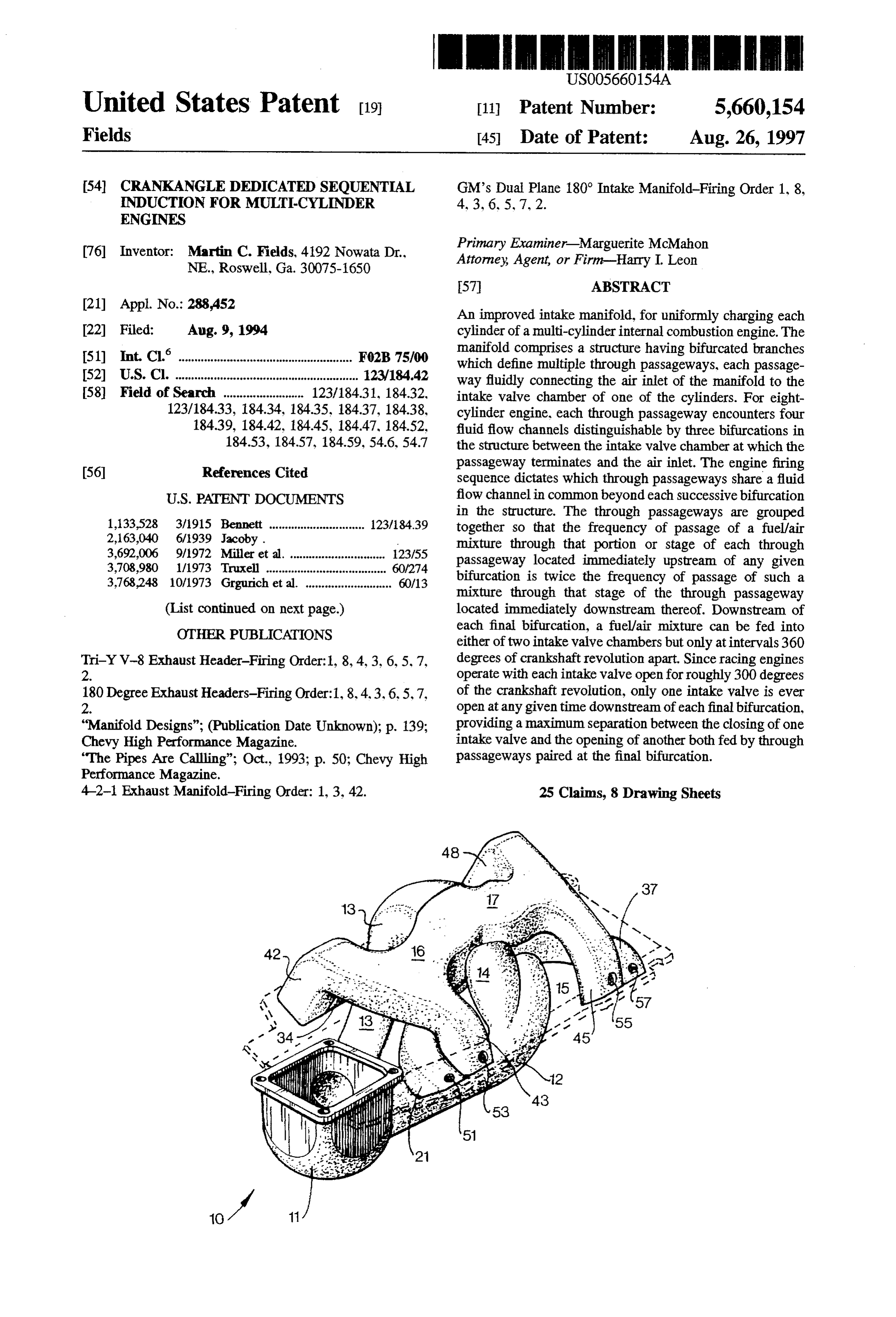
United States Patent 19 11 Patent Number: 5,660,154 Fields 45 Date of Patent: Aug. 26, 1997 54 CRANKANGLE DEDICATED SEQUENTIAL GM's Dual Plane 180° Intake Manifold-Firing Order 1, 8, NDUCTION FOR MULTI-CYLNDER 4, 3, 6, 5, 7, 2.
ENGINES
76 Inventor: Martin C. Fields, 41.92 Nowata Dr. Primary Examiner Marguerite McMahon NE. Roswell, Ga. 30075-1650 Attorney, Agent, or Firm-Harry I. Leon
(21) Appl. No.: 288,452 An improved intake manifold, for uniformly charging each 22 Filed: Aug. 9, 1994 cylinder of a multi-cylinder internal combustion engine. The (51) int. Cl. ... F02B 7500 manifold comprises a structure having bifurcated branches which define multiple through passageways, each passage 52) U.S. Cl. ............................................. 123/184.42 way fluidly connecting the air inlet of the manifold to the 58) Field of Search ......... ... 123/18431, 18432, intake valve chamber of one of the cylinders. For eight 123/184.33, 184.34, 184.35, 18437, 18438, cylinder engine, each through passageway encounters four 18439, 184.42, 18445, 184.47, 184.52, fluid flow channels distinguishable by three bifurcations in 184.53, 18457, 184.59, 54.6, 54.7 the structure between the intake valve chamber at which the (56 References Cited passageway terminates and the air inlet. The engine firing sequence dictates which through passageways share a fluid
in the structure. The through passageways are grouped 1,133,528 3/1915 Bennett ............................. 123/84.39 together so that the frequency of passage of a fuel/air 2,163,040 6/1939 Jacoby. mixture through that portion or stage of each through 3,692,006 9/1972 Miller et al. .............................. 123/55 passageway located immediately upstream of any given 3,708,980 1/1973 Truxell ................ ... 60/274 3,768,248 10/1973 Grgurich et al. ........................... 60/13 bifurcation is twice the frequency of passage of such a mixture through that stage of the through passageway
(List continued on next page.) located immediately downstream thereof. Downstream of OTHER PUBLICATIONS each final bifurcation, a fuel/air mixture can be fed into either of two intake valve chambers but only at intervals 360
Tri-YV-8 Exhaust Header-Firing Order:1, 8, 4, 3, 6, 5, 7, degrees of crankshaft revolution apart. Since racing engines 2. operate with each intake valve open for roughly 300 degrees 180 Degree Exhaust Headers-Firing Order:1, 8, 4.3, 6,5,7, of the crankshaft revolution, only one intake valve is ever 2. open at any given time downstream of each final bifurcation, "Manifold Designs"; (Publication Date Unknown); p. 139; providing a maximum separation between the closing of one Chevy High Performance Magazine. intake valve and the opening of another both fed by through "The Pipes Are Calling"; Oct., 1993; p. 50; Chevy High passageways paired at the final bifurcation. Performance Magazine.
4-2-1 Exhaust Manifold-Firing Order: 1, 3, 42. 25 Claims, 8 Drawing Sheets
Page 2
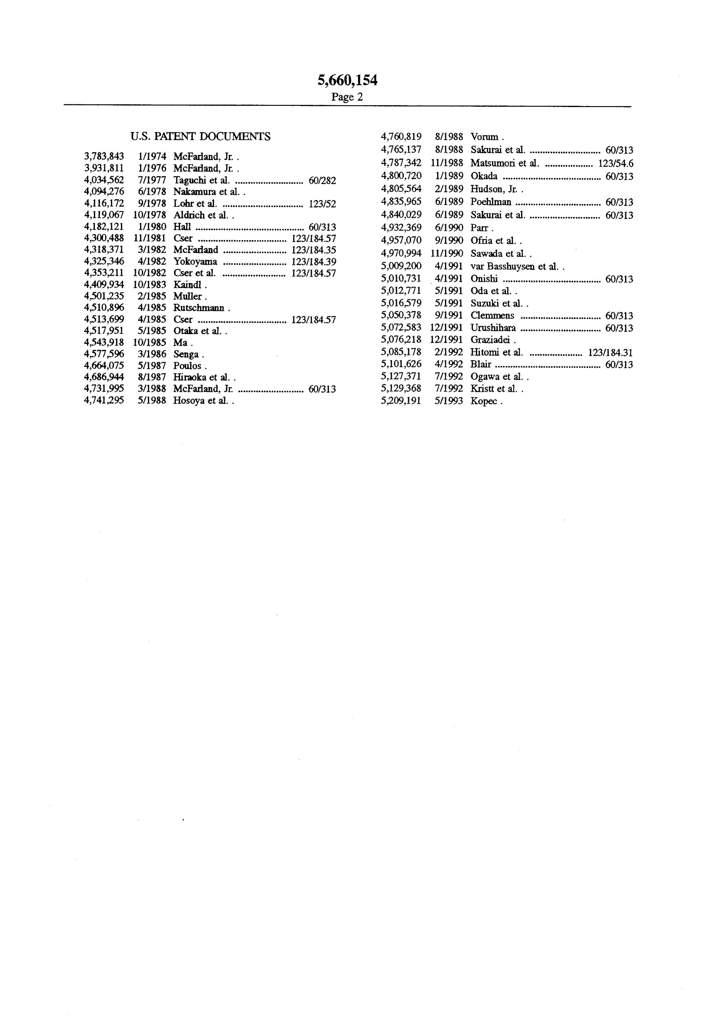
4,765,137 8/1988 Sakurai et al. ............................ 60/313 3,783,843 1/1974 McFarland, Jr. . 4,787,342 11/1988 Matsumori et all 123/54.6 3,931,811 1/1976 McFarland, Jr. . 4800,720 1/1989 Okada 60/33 4,034,562 7/1977 Taguchi et al. ........................... 60/282 www.s 7 aw 1 V1 Wasaws1.s sees see ess ovoo are are so so a sae sesses sps 4,094,276 6/1978 Nakamura et al. . 4,805,564 2/1989 Hudson, Jr. .
4,116,172 9/1978 Lohr et al. ................................ 123/52 4,835,965 6/1989 Poehlman .................................. 60/33 4,119,067 10/1978 Aldrich et al.. 4,840,029 6/1989 Sakurai et al. ............................ 60/33 4,182,121 1/1980 Hall ........................................... 60/313 4,932,369 6/1990 Parr.
4,300,488 11/1981 ... 123/84.57 4,957,070 9/1990 Ofria et al..
4,318,371 3/1982 ... 123/84.35 4,970,994 11/1990 Sawada et al..
4,325,346 4/1982 ... 23/84.39 5,009,200 4/1991 var Basshuysen et al. . 4,353,211 10/1982 O - .... .. . . .. . 123/84.57
4,409,934 10/1983 5010,731 4/1991 Onishi ....................................... 60/313 4.501,235 2/1985 5,012,771 5/1991. Oda et al. .
4510,896 4/1985 5,016,579 5/1991 Suzuki et al..
- 5,050,378 9/1991 Clemmens ................................ 60/313 : E. 5. it." easoe as a sease 123/184.57 5,072,583 12/1991 Urushihara ................................ 60/313 4,543,918 10/1985 Ma. 5,076,218 12/1991 Graziadei.
4,577,596 3/1986 Senga. 5,085,178 2/1992 Hitomi et al. ..................... 123/18431 4,664,075 5/1987 Poulos. 5,101,626 4/1992 Blair.......................................... 60/313 4,686,944 8/1987 Hiraoka et al.. 5,127,371 7/1992 Ogawa et al. .
4,731,995 3/1988 McFarland, Jr. .......................... 60/313 5,129,368 7/1992 Krist et al. .
4,741.295 5/1988 Hosoya et al.. 5,209,191 5/1993 Kopec.
Page 3
Drawing sheet — no readable text.
Page 4
Drawing sheet — no readable text.
Page 5
Drawing sheet — no readable text.
Page 6
Drawing sheet — no readable text.
Page 7
Drawing sheet — no readable text.
Page 8
Drawing sheet — no readable text.
Page 9
-- - - - - - - - - - - - - - - - - - - - - - - - - - - - - - - - -
/ o / 6 2 | | 5 , ( 3 Y. ? 4 Y \ 1 '. \ N N
Page 10
ra -- m - s Y Ya - N. / N 1 / - N
Y -- \ || Y \ N Y -- -- - - - -- - m ar- w - - - -- - - - -- - - - -- - --
Page 11
CRANKANGLE DEDICATED SEQUENTIAL Similarly, until now, improved manifolds for six cylinder NDUCTION FOR MULTICYLNDER engines have still allowed two or more cylinders to be open ENGINES simultaneously to the intake side of the engine, in a con
BACKGROUND OF THE INVENTION
figuration in which the cylinders are fluidly connected to a passageway which they share in common and which is so
The present invention relates to an improvement in the located immediately upstream relative to the individual intake manifold structure for any two- or four-stroke internal cylinders. Prior art improvements in manifolds for six cyl combustion engine having an even number of cylinders inder engines have been directed towards increasing the above four. Among the engines on which this manifold length of the interval separating the flow of charges to structure can be mounted are typical V-8 engines, each such 10 cylinders which are fluidly interconnected in groups of engine having two banks of cylinders, one disposed on the threes rather than in the optimum groups of twos. left and one on the right. An intake manifold for distributing The state-of-the-art with respect to various manifolds for charges of fuel and air or of air alone among the respective six cylinder engines can be appreciated by comparing the cylinders is interposed between the left and right cylinder exact number of degrees of crankshaft revolution during banks. 15 which two or more cylinders are open, hereinafter referred Engine performance can be enhanced by using a manifold to as the "simultaneously-open valves interval.” For a given in which the resistance to fluid flow therewithin is mini engine, this interval is determined by subtracting the number mized and in which the inertia of the intake air is utilized to of degrees of crankshaft revolution during which charge advantage. Resistance to fluid flow varies with the cross 20 passes through the first passageway which two or more sectional flow area and length of each passageway within the cylinders share in common located upstream of their indi manifold connecting the air inlet thereof to an individual vidual fluid flow channels, this number of degrees being cylinder of the engine. Fluid flow resistance is also depen hereinafter referred to as the "first common upstream section dent upon any changes in cross-sectional area along the pulse interval", from the total number of degrees of crank passageway. The inertia of the intake air gives rise to flow 25 shaft revolution during which any one cylinder remains pulses caused by pressure waves bouncing off of just-closed open, hereinafter referred to as the "open valve duration". In air intake valves. In good manifold design, the flow pulses a typical racing engine, the "open valve duration” is roughly are minimized and even used to help pressurize the flow 300 degrees.
entering yet-to-be-charged cylinders as they are being fed Manifolds six-cylinder engines in which one flow channel sequentially in the firing order. 30 at the air inlet branches into six runners, each runner being In addition, the need for a manifold capable of providing fluidly connected to one of the cylinders, have a “first a uniform distribution of fluid flow to all engine cylinders common upstream section pulse interval" of 120 degrees. has long been recognized. Uneven filling of cylinders with The "simultaneously-open valves interval" for two intake their respective charges of fuel and air or of air alone results valves with such a manifold is then 180 degrees of crank in each cylinder not doing the same of work. An attempt 35 shaft revolution. During this 180 degree interval, three solving this problem is found in U.S. Pat. No. 2,163,040, intake valves will be open simultaneously 60 degrees, the where, as early as 1939, Jacoby provided a manifold for a valves being in varying states of travel. four cylinder engine. Alternately, more advanced manifolds for six-cylinder Aldrich and Sawruk, in U.S. Pat. No. 4,119,067, which engines according to the prior art have one flow channel at issued in 1978, improved upon Jacoby's combination by the air inlet branching into two transfer sections. each centrally locating the carburetor on a four cylinder engine section feeding a bank of the engine and branching into three between its second and third cylinders. runners, each runner being fluidly connected to one of the Vorum, in U.S. Pat. No. 4.760,819, which issued in 1988, cylinders. Such manifolds have a "first common upstream disclosed a manifold on which the carburetor is symmetri section pulse interval” or pulse interval of each bank of 240 cally positioned with respect to the cylinders of a four 45 degrees. With such a manifold, the "simultaneously-open cylinder engine. Vorum also realized that an intake manifold valves interval” is reduced to 60 degrees (still substantially can be divided into sets of primary and secondary runners greater than 0 degrees), during which two intake valves are for use on such an engine. open simultaneously, of each crankshaft revolution. Oda et al., in U.S. Pat. No. 5.012,771, issued in 1991, In general, for engines having six or more cylinders, the realized the advantages of having a manifold for a four 50 prior art has failed to solve those problems which are caused stroke engine wherein the manifold has-two groups of by having two or more cylinders open simultaneously in a discrete intake passages connected to two groups of cylin manifold configuration in which these cylinders are fed by ders which in each and the same-group are not intended to a flow passageway they share in common located immedi be fired one after another, respectively. ately upstream of those flow channels serving the individual With respect to pioneering work outside of the patent 55 cylinders, respectively.
literature, Edlebrock, beginning in 1938, sought to minimize SUMMARY OF THE INVENTION the effects of the same portion of the manifold simulta neously feeding charges to two cylinders of a V-8 engine. The primary object of this invention is to provide an However, Edelbrock's manifolds, including his dual layer improved manifold for an internal combustion engine hav models, allow for a substantial amount of interference to ing greater than four cylinders in which the manifold can occur between charges fed into even those pairs of cylinders evenly distribute charges of air/fuel mixture or of air alone most separated from each other in the firing sequence. In his to the cylinders as well as take advantage of the pulsed combinations, these pairs of cylinders are fluidly connected nature of the flow of these charges. in such a way that a charge must be fed every 180 degrees A further object of this invention is to provide an of crankshaft revolution through a passageway shared in 65 improved manifold which evenly separates, by a certain common by the cylinders and located immediately upstream number of degrees of crankshaft revolution, each charge as of the flow channel serving each cylinder individually. the charge is being fed into each cylinder of an internal
Page 12
combustion engine from any charges previously fed, or The air inlet section of the improved manifold for an which might be subsequently fed, into those cylinders clos eight-cylinder engine takes in a charge of fuel/air or of air est to said cylinder in the firing sequence of the engine. alone every 90 degrees of crankshaft revolution while a A still further object of this invention is to provide an charge flows through each dual transfer section every 180 improved manifold-having means for isolating, in varying degrees. Flow through any one of the four distribution degrees, charges as they are moving through passageways sections does not occur again until the engine has advanced feeding into the individual cylinders of the engine, the half-way (360 degrees) through its firing order. Hence, for a degree of isolation increasing with the proximity of the typical engine in which any one intake valve is open for but cylinders to each other in the firing sequence of the engine, 300 degrees of crankshaft revolution, only one of the two so that charges fed into those cylinders which are fired 10 intake valves which can be fed by a given distribution immediately one after the other are most isolated from each section is being serviced at any given time. other.
Two preferred embodiments include a first manifold hav
A still further object of this invention is to provide a ing a multi-layered structure defining the distribution sec manifold having much better flow characteristics due to tions and a second manifold having dual branches formed at charge separation which not only results in the virtual each of several Ys, the branches forming a structure dis elimination of interference between incoming flow and 15 posed pressure waves created in the manifold when previously bisectssymmetrically the structure about a vertical plane which generally of Ys longitudinally. In both of these filled intake valves close but also allows such a pressure embodiments, both the air inlet section and the dual transfer wave to build at the right instant to help initiate flow into an sections are virtually the same. intake valve that is about to open rather than to hamper its 20 Improved manifolds according to the present invention flow.
An additional object of the present invention is to provide utilizing the multi-layered structure can be used on any an improved manifold having fluid flow channels with large V-12 engines.four-stroke, conventional
The
V engine, including V-6, V-8 and alternate embodiment, on the other hand, enough cross-sectional areas to accommodate increased requires, for eight-cylinder engines, the following dedicated cylinder charging through the utilization of lower than usual 25 firing order:
without these flow velocities being too low for efficient 1-6-5-2-3-8-7-4.
cylinder filling at low engine speeds. For V-8 engines having a conventional crankshaft Another additional object is to provide an improved configuration, the improved manifold having the multi manifold which can be used to broaden the rpm range of layered structure comprises three layers. The lower and useable torque for an engine while flattening its torque middle layers thereof comprise two distribution sections, curve, the manifold being tuned to achieve multiple indi each section discharging through two branches or intakeport vidual torque boosts. extensions. Each of the two intake port extensions supplied In accordance with the present invention, there is pro by each of these layers feeds charges of fuel/air or of air vided an improved manifold for engines having more-than alone to a cylinder located in a different bank of the engine four cylinders, the manifold having progressively branching 35 than the other intake port extension supply by the same sections which define multiple through passageways, each layer. The upper layer, by contrast, defines four intake port passageway fluidly connecting the air inlet of the manifold extensions, two of these extensions feeding one engine bank to the intake valve chamber of one of the cylinders. With this and two the other bank.
manifold, charges are fed through one of a plurality of For example, an improved manifold having a multi shared flow channels, to either of two cylinders fluidly layered structure suitable for use with a V-8, four-stroke connected thereto, each shared flow channel being disposed engine, such as that utilized by Chevrolet, has an upper layer at one of the points of branching located furthest defining four intake port extends which feed cylinders 3,5 downstream, the charges flowing through the shared flow and 8. The middle layer has extensions supplying cylinders channel to the individual cylinders being separated by 360 4 and 7; and the lower layer cylinders 1 and 6. With this degrees of crankshaft revolution for a four-stroke engine and 45 three-layer delivery system, no distribution section has to 180 degrees for a two-stroke engine. share an inlet flow to two cylinders simultaneously. For Moreover, each successive branching along each of the example, immediately after cylinder 1 is fed from the lower through passageways adds another degree of freedom in the layer, the next firing cylinder, cylinder 8, is fed from the top design of a manifold. For improved manifold, according to layer. Moreover, the pressure pulse from the closing of the present invention, these degrees of freedom can be 50 intake valve 1 immediately enters the lower layer distribu utilized to enhance the engine efficiency over a wide range tion section where the pressure pulse aids in initiating flow of engine speeds. Each additional degree of freedom can be from the same distribution section into cylinder 6. - translated into another separate torque peak, created by The improved manifold having a multi-layered structure resonance phenomena, each torque peak being a function of is further characterized by having each of the through the revolutions per minute (rpm) of the engine. The 55 passageways linking one of the intake valves to the improved manifold according to the present invention pro carburetor, or the like, being approximately the same in vides three degrees of freedom for-the six-cylinder engine, length as any one of the other through passageways. four degrees of freedomfor the eight-cylinder engine and for In an alternate embodiment for a V-8 engine comprising the twelve-cylinder engine and five degrees of freedom for dual branches formed at each of seven Ys, the branches the sixteen-cylinder engine. forming a structure disposed symmetrically about a vertical For a typical eight-cylinder engine, the manifold com plane bisecting the structure longitudinally, each transfer prises an air inlet section, a transfer section, a distribution section has a common fluid flow channel dedicated to section and an air intake port extension section. The air inlet through passageways linking the airinlet of this manifold to section branches into two transfer sections, each transfer cylinders within one particular bank of the engine. section itself branches into two distribution sections, and 65 Preferably, the symmetrically disposed flow paths for the each of the distribution sections branches into two individual through passageways of this embodiment are designed to air intake port extensions. have sweeping, gradual turns in direction.
Page 13
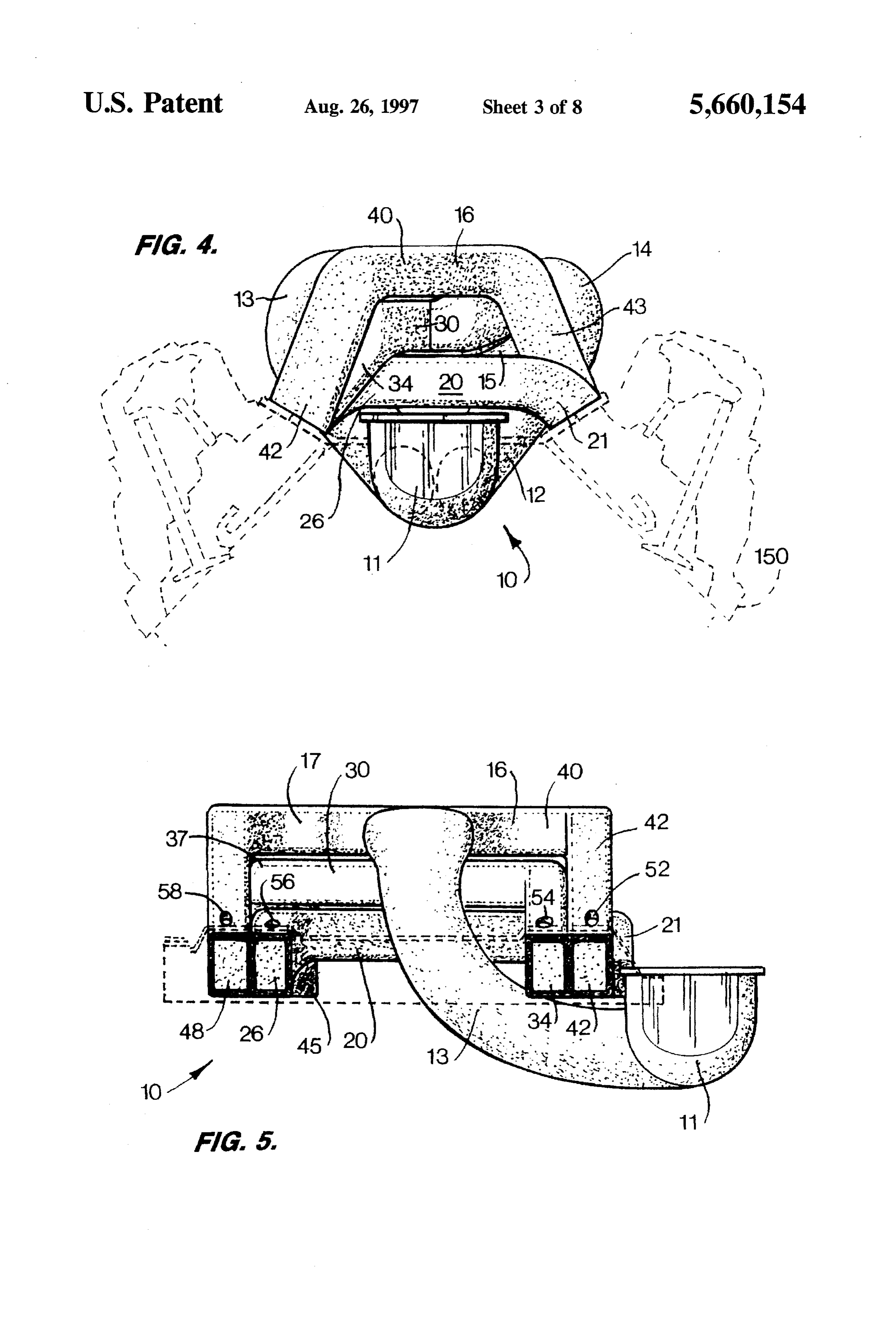
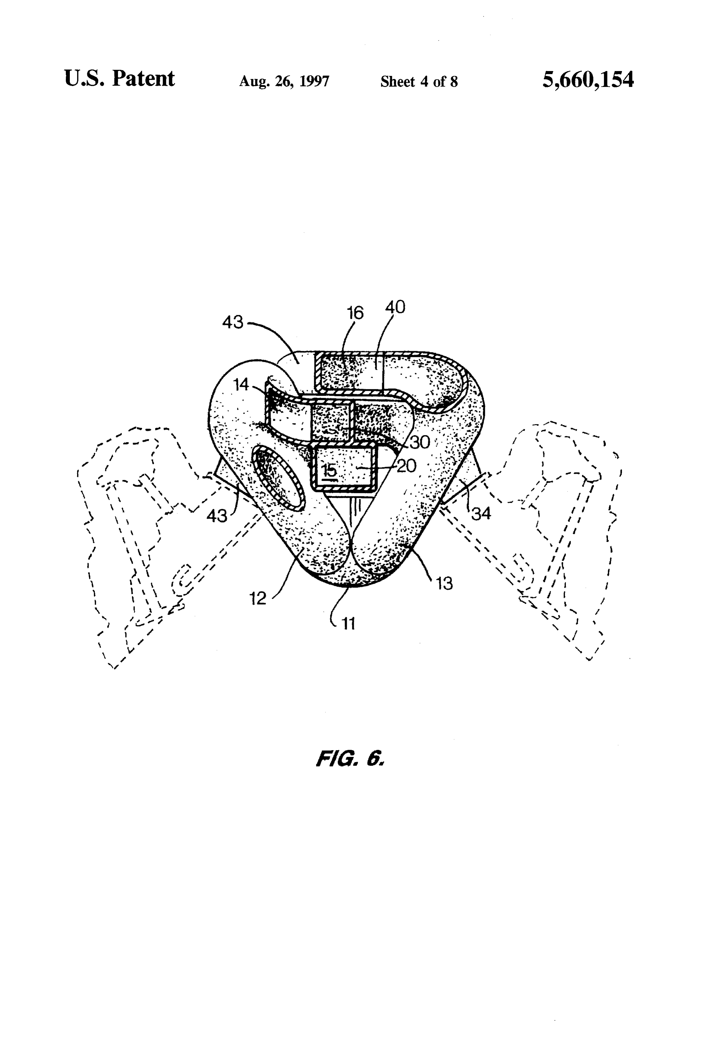
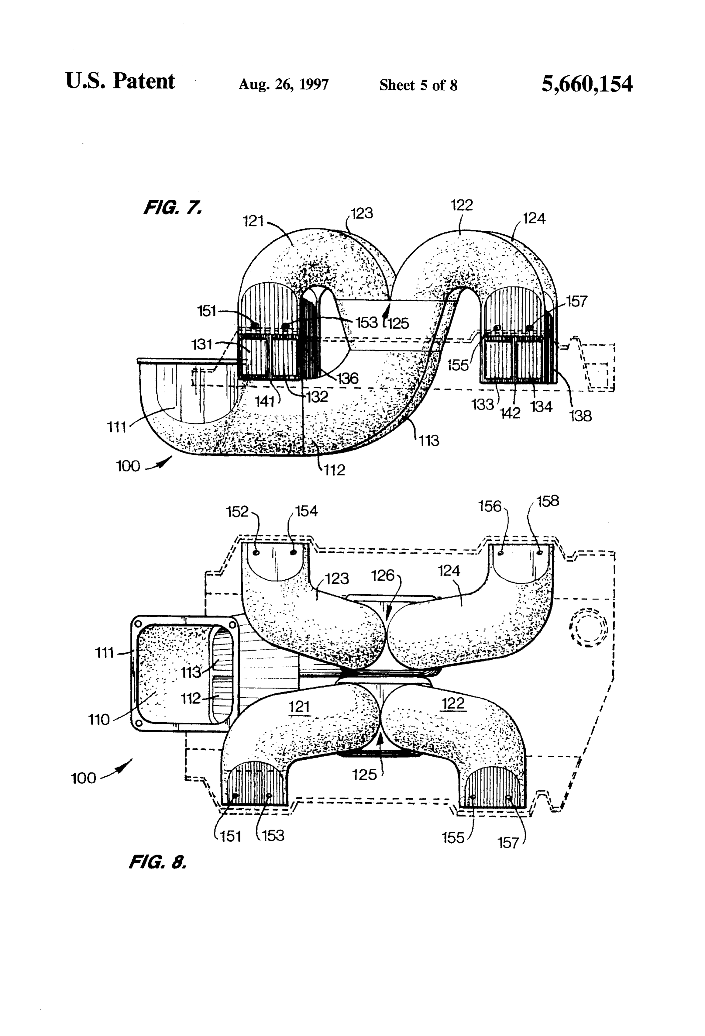
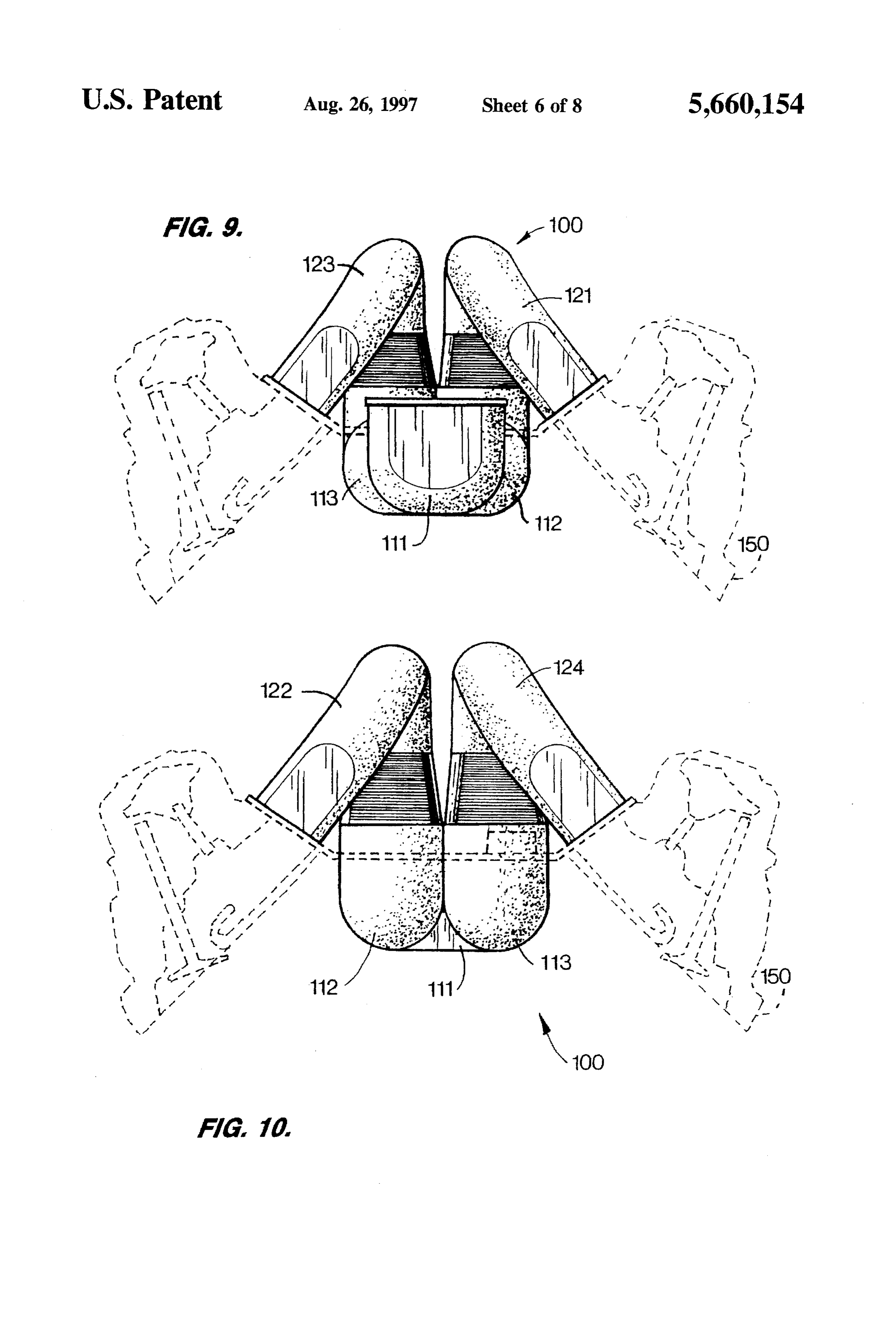
Preferred embodiments of the improved manifold suitable FIG. 9 is a front end view of the manifold according to for six-cylinder engines comprise an air inlet section which FIG. 7, the mounting flange used to connect the manifold to branches into three transfer sections, each of the transfer the engine and the engine cylinder heads being shown in sections branching into two intake port extensions. For an in dashed lines;
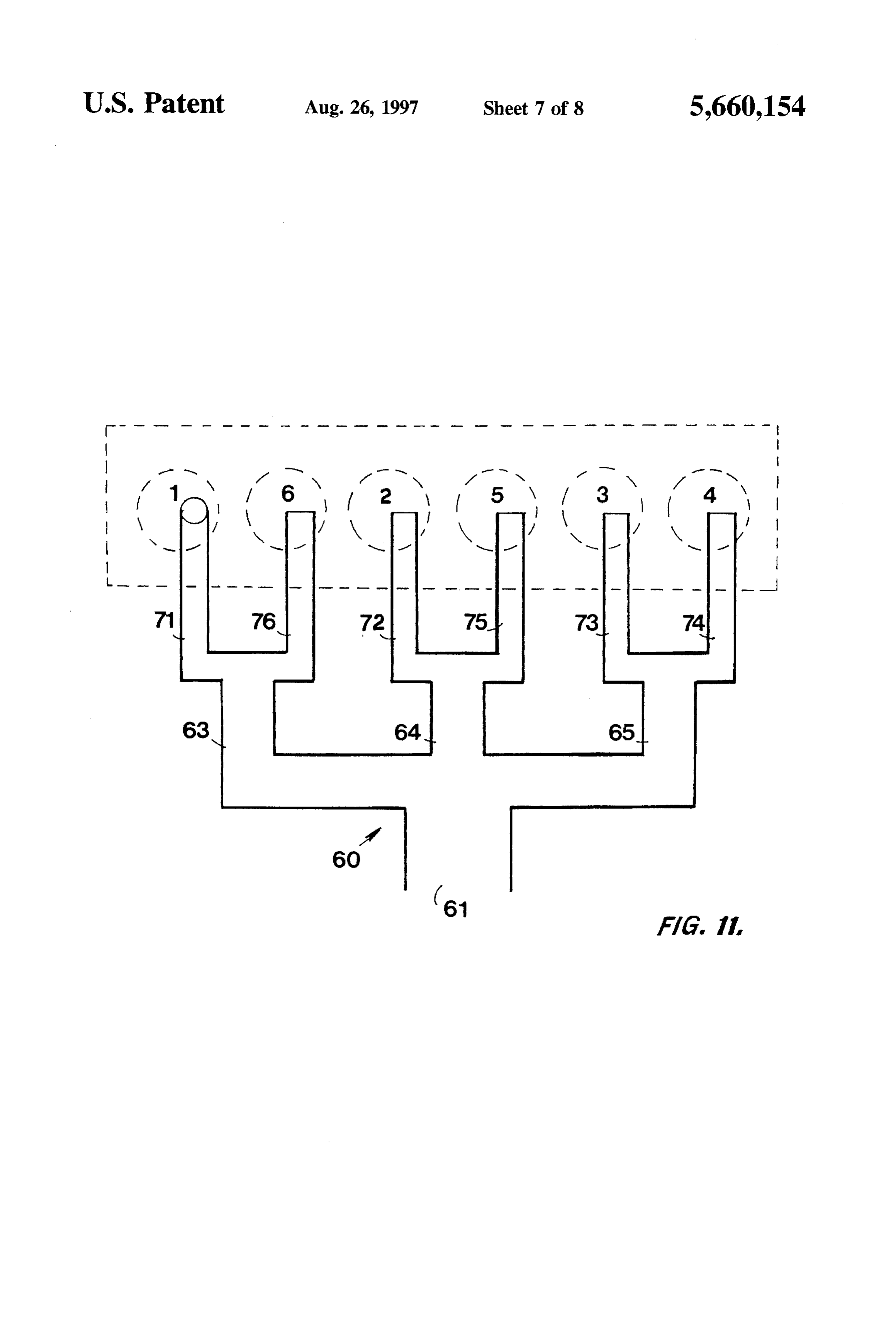
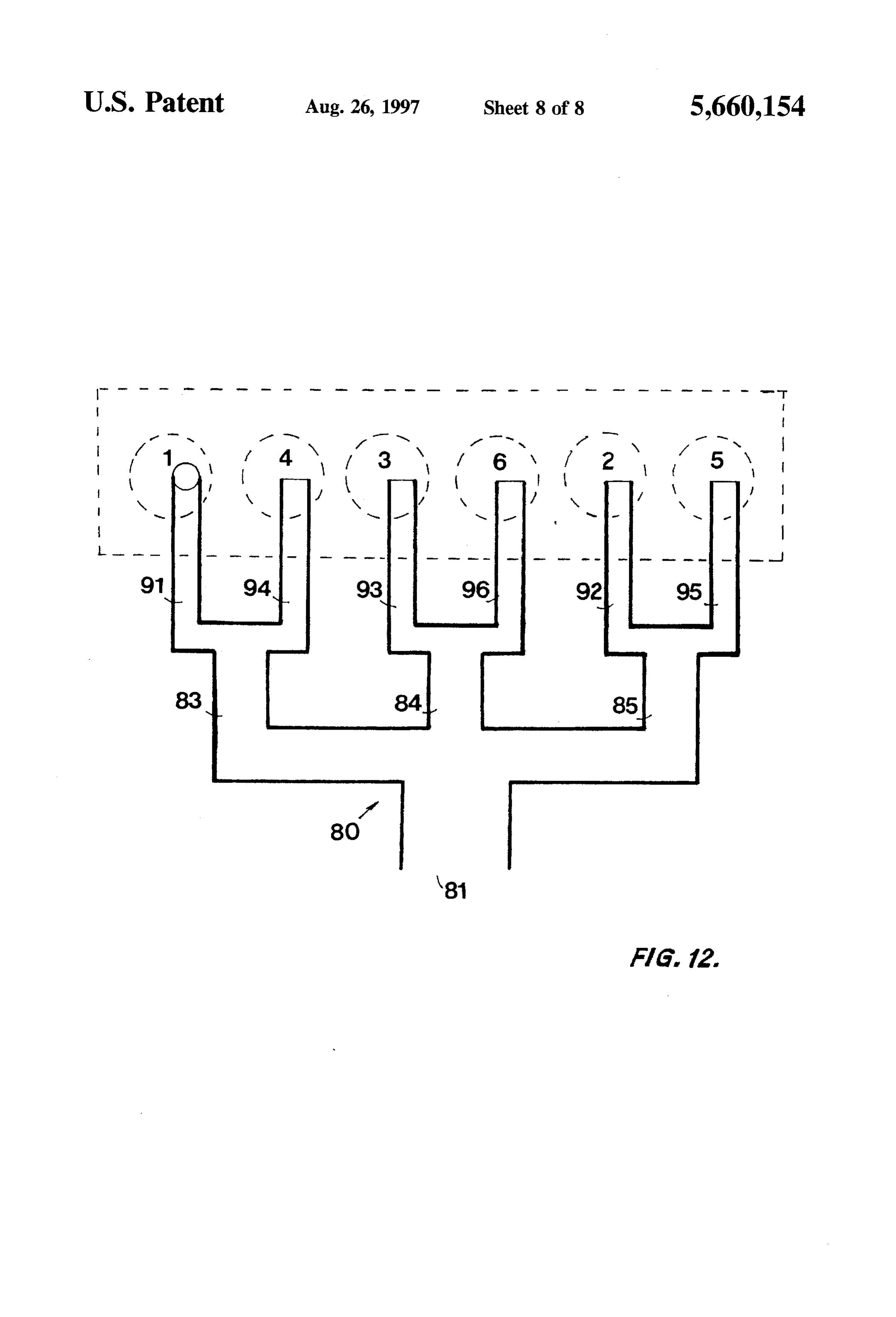
line engine having a firing order of 1-5-3-6-2-4, the three FIG. 10 is arear end view of the manifold according FIG. transfer sections are grouped to supply charges to cylinders 7, the mounting flange used to connect the manifold to the and 6; 2 and 5; and 3 and 4, respectively, thereby giving a engine and the engine cylinder heads being shown in dashed maximum time interval between charges passing through the lines; and same transfer section. Similarly, for a V-6 engine such as a
Chevrolet which has a firing order of 1-6-5-4-3-2, the three O FIGS. 11 and 12 are schematics of alternate embodiments transfer sections are grouped to supply charges to cylinders of the manifold according to the present invention, the 1 and 4; 3 and 6; and 2 and 5, respectively, again giving a embodiments being useful on an inline six-cylinder engine separation corresponding to 360 degrees crankshaft revolu and on a V-6 engine such as the Chevrolet, respectively. tion before the next cylinder is again fed by the same distribution section. DETALED DESCRIPTION OF THE . While embodiments have been disclosed for use with V-8 15 PREFERRED EMBODIMENTS and six-cylinder engines, the same design philosophy can be equally well applied to any engine having an even number The present invention will be described more in detail of cylinders. That is, sequential discharges from the mani with reference to the accompanying drawings. Correspond fold to its respective intake valves do not simultaneously ing reference characters indicate corresponding parts traverse the same distribution section but rather are sepa 20 throughout the several views of the drawings. rated from each other by a time interval corresponding to The drawings illustrate four embodiments/of the manifold 360 degrees of crankshaft revolution for a four-stroke according to the present invention. The first of these engine, or 180 degrees for a two-stroke engine, before the embodiments, which includes a tri-layered structure, is next cylinder is again fed through the same distribution indicated generally by the reference numeral 10. section. That is, the design of the manifold is such that 25 As illustrated in FIGS. 1-6, the manifold 10 can be sequential discharges from the manifold to its respective intake valves occur in the same distribution section but are mounted using a mounting flange, an example of which is as far removed from each other in degrees of crankshaft shown in dashed lines on a typical V-8 block such as the revolution as is possible. Furthermore, the pressure pulse small block Chevrolet engine. The small block Chevrolet created on an intake valve closing is sent to the immediately engine is used for illustrative purposes only and slight upstream distribution section at an instant when the pressure modifications of the manifold 10 will allow it to be used on pulse can be most helpful. By a timely increase in the local other V-8 engines. The manifold 10 is mounted in the center pressure differential, the pressure pulse initiates flow from of the V so that the distance which fluid must travel from the the same distribution section to the intake port extension of air inlet of the engine to each of the cylinders is approxi the next cylinder in the charging sequence. 35 mately the same for all of them.
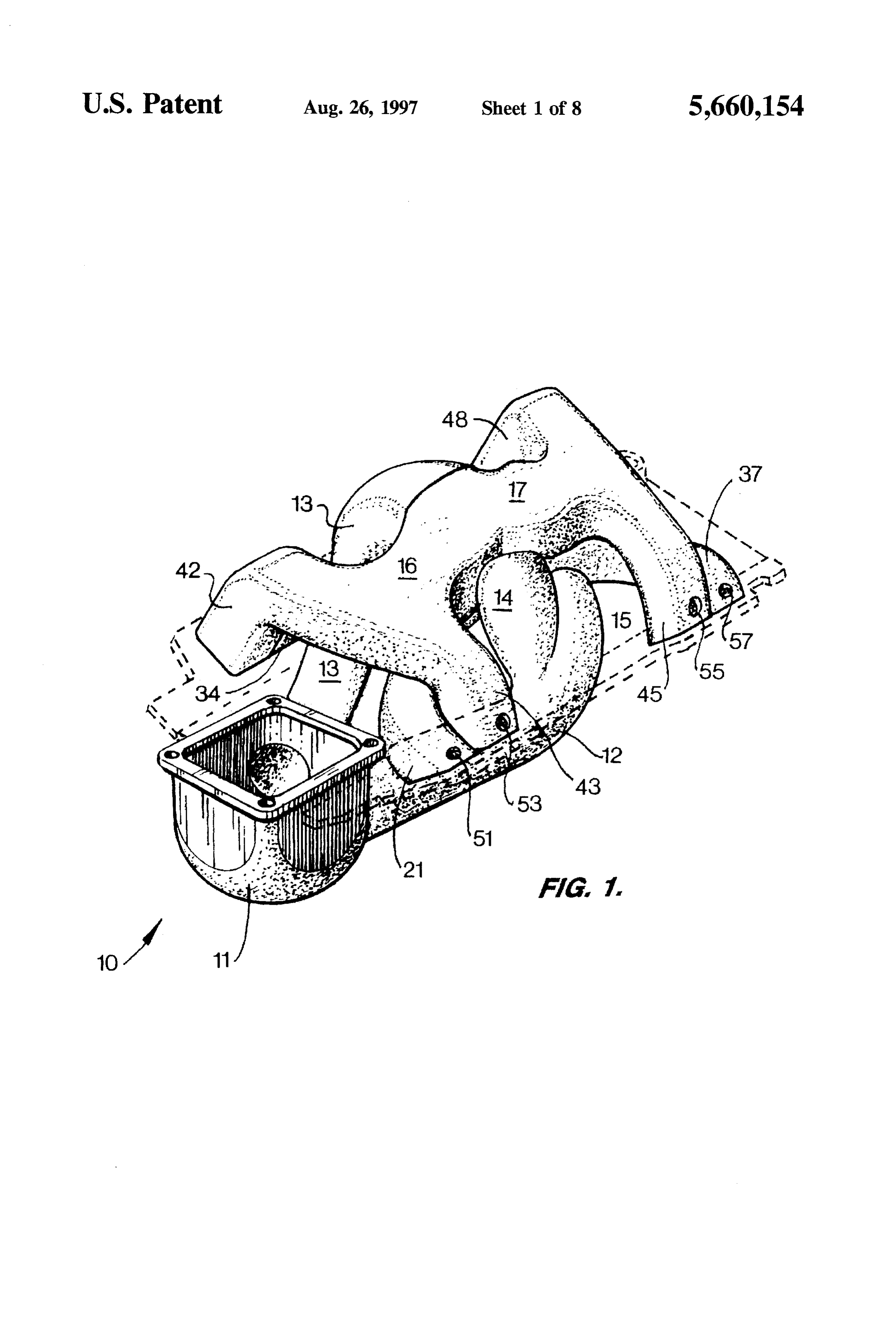
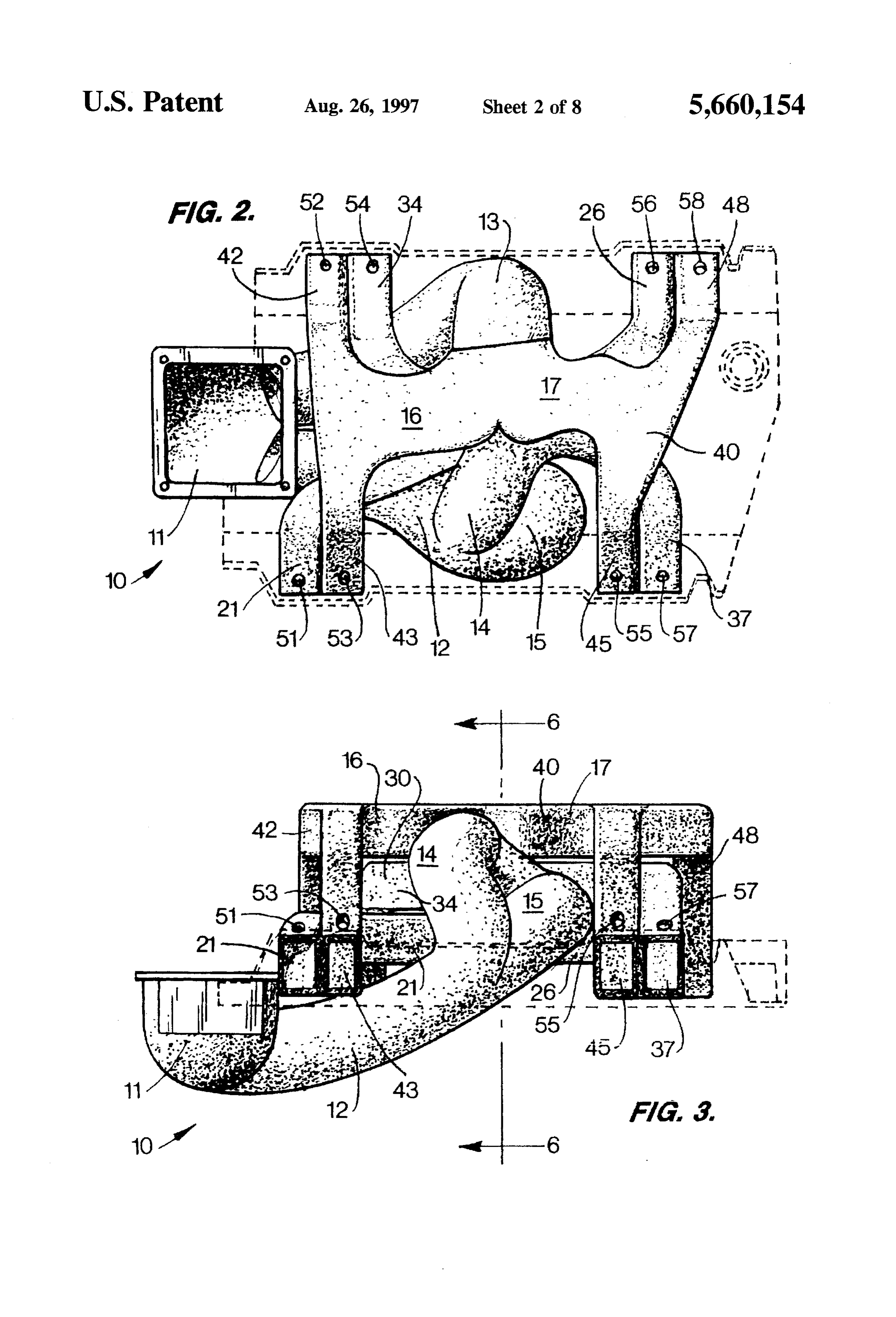
BRIEF DESCRIPTION OF THE DRAWINGS The manifold 10 has the following major components: an air intake section 11, transfer sections 12, 13, distribution
FIG. 1 is a perspective view of one embodiment of the sections 14, 15, 16, 17, and intake port extensions 21,26,34, intake manifold according to the present invention, the 37, 42, 43, 45.48. Air intake section 11 is fluidly connected mounting flange used to connect the manifold to the engine to transfer sections 12, 13 which in turn are fluidly con being shown in dashed lines; nected to distribution sections 14 and 15; 16 and 17, FIG. 2 is a top plan view of the intake manifold according respectively. Distribution sections 14, 15, 16, 17 are them to FIG. 1, the mounting flange used to connect the manifold selves fluidly connected to intake port extensions 34 and 37; to the engine being shown in dashed lines; 21 and 26; 42 and 43; 45 and 48, respectively. The intake FIG. 3 is a right side elevational view of the intake 45 valve chambers of the engine are fluidly connected to the manifold according to FIG. 1, the mounting flange used to distribution sections by the intake port extensions 21, 26 connect the manifold to the engine being shown in dashed protruding from the lower layer 20 of the tri-layered lines; structure, extensions 34, 37 protruding from its middle layer FIG. 4 is a front end view of the intake manifold accord 30 and extensions 42, 43, 45, 48 protruding from its upper ing to FIG. 1, the mounting flange-used to connect the 50 layer 40.
manifold to the engine and the engine cylinder heads being The manifold 10 also includes provisions for the instal shown in dashed lines; lation of fuel injectors which can be located in mounting FIG. S is a left side elevational view of the intake holes 51, 52, 53, 54, 55,56, 57 and 58. manifold according to FIG. 1, the mounting flange used to connect the manifold to the engine being shown in dashed 55 EXAMPLE 1. lines; In a typical application, manifold 10 is utilized on a Small FIG. 6 is a cross-sectional view Of the manifold taken block Chevrolet V-8 engine. The Chevrolet V-8 engine is along line 6-6 of FIG. 3, the mounting flange used to arranged in two banks of cylinders, right and left, looking connect the manifold to the engine and the engine cylinder from the front of the vehicle. The cylinders of this engine heads being shown in dashed lines; number from the front with the front right cylinder being FIG. 7 is a side elevational view of an alternate embodi cylinder 1, the front left 2, the second-from-the-front right 3, ment of the intake manifold according to the present the second-from-the-front left 4, the third-from-the-front invention, the mounting fange used to connect the manifold right 5, the third-from-the-front left 6, the fourth-from-the to the engine being shown in dashed lines; front right 7, and the fourth-from-the-front left 8. The FIG. 8 is a top plan view of the manifold according to 65 ignition firing order for this V-8 engine is 1-8-4-3-6-5-7-2. FIG.7. the mounting flange used to connect the manifold to and the cylinders are fired in sequence at intervals which are the engine being shown in dashed lines; 90 degrees of crankshaft revolution apart.
Page 14
With this engine, the manifold 10 is arranged so that the is spatially separated from extension 37, which has justfed distribution section 15 located in the lower layer 20 supplies cylinder 7, by four distinguishable fluid flow channels cylinders land 6 through air intake port extensions 21 and defined by transfer sections 12 and 13 and by distribution 26, respectively. Distribution sections located in the middle sections 14 and 16.
layer 30 supplies cylinders 4 and 7 through air intake port The next cylinder to fire again is cylinder 1 restarting the extensions 34 and 37, respectively. Distribution sections 16, firing sequence. Cylinder 1 is fed through distribution sec 17 in the upper layer 40 supply cylinders 2 and 3; 5 and 8, tion 15 in the lower layer 20 by extension 21 which is respectively, through airintake port extensions 42 and 43; 45 spatially separated from extension 42 by four distinguish and 48, respectively. able fluid flow channels defined by transfer sections 12 and As indicated by the firing order, ignition of cylinder 6 is 10 13 and by distribution sections 15 and 16. separated from the ignition of cylinder 1 but an interval For each of the cylinders-cylinders 8, 4, 3, 6, 5, 7, 2, 1, corresponding to 360 degrees of crankshaft revolution. the manifold 10 provides good separation between the intake Similarly, cylinders 8 and 5, cylinders 4 and 7, cylinders 3 flow for each individual cylinder and the pressure pulse and 2 are ignited at time intervals which are separated by created by the cloying of the intake valve of cylinder 1, 8, 360 degrees of crankshaft revolution. Therefore, the sharing 15 4, 3, 5, 6, 7, 2, 1, respectively. of the same distribution section 15, 17, 14, 16 by pairs of An alternate embodiment of the improved manifold is cylinders 1 and 6, 8 and 5, 4 and 7,3 and 2, respectively, has shown no adverse effect on the opening of the intake valve of either referencein numeral
FIGS. 7-10 and is indicated generally by the 100. The manifold 100, as illustrated in cylinder in each of these pairs.
20 the drawings, is designed for use with an eight-cylinder
Moreover, after the intake valve for cylinder 1 opens, engine wherein the cylinders are arranged in two banks of cylinder 8, the next cylinder to receive intake flow, is fed four cylinders each arranged in a V pattern commonly called through the distribution section 17 in the upper layer 40 by a V-8 engine, but with the Crankshaft being dedicated to a air intake port extension 48. Extension 48 is spatially firing order which works with the manifold 100: specifically, separated from extension 21, which has justfed cylinder 1, by four distinguishable fluid flow channels defined by trans 25 a firing
For an
eight-cylinder engine, the manifold 100 can be fer sections 12 and 13 and by distribution sections 15 and 17. characterized generally as comprising seven Ys and has the Hence, manifold 10 provides good separation between the following major components: an air inlet section 111; trans intake flow for cylinder 8 and the pressure pulse created by: fer sections 112, 113; distribution sections 121, 122, 123, the closing of the intake valve of cylinder 1. 30 124; air intake port extensions 131, 132,133,134, 135,136, Similarly, cylinder 4, the next cylinder to receive intake 137,138. The airinlet section 111 is fluidly connected to the flow after cylinder 8, is fed through the distribution section transfer sections 112 and 113 through a Y. The transfer 14 in the middle layer 30 by air intake port extension 34. section 112
Extension is spatially separated from extension 48, Which 121 and 122isthrough fluidly connected to the distribution sections has just fed cylinder 8, by four distinguishable fluid flow 35 is fluidly connected toathe Y 125, and the transfer section 113 distribution sections 123 and 124 channels defined by transfer sections 12 and 13 and by through a Y 126. The peripheries of transverse cross distribution sections 14 and 17.
sections of fluid flow channels formed by the distribution
Likewise, cylinder 3, the next cylinder to receive intake sections 121, 122, 123, 124 are generally circular in shape. flow after cylinder 4, is fed through the distribution section Each distribution section 121, 122,123,124 is split into two 16 in the upper layer 40 by air intake port extension 43. intake port extensions by flow dividers. As shown in FIG.7, Extension is spatially separated from extension 34, which distribution sections 121 and 122 are split into extensions; has just fed cylinder 4, by four distinguishable fluid flow 131; 132; 133,134, respectively, by flow dividers 141,142, channels defined by transfer sections 12 and 13 and by respectively. Each of the intake port extensions also has a distribution sections 14 and 16. port 151, 152, 153, 154, 155, 156, 157, 158, for mounting After cylinder 3, cylinder 6, the next cylinder to receive 45 fuel injectors (not shown) when they are utilized in the intake flow, is fed through the distribution section 15 in the engine.
lower layer 20 by air intake port extension 26. Extension 26 EXAMPLE 2 is spatially separated from extension 43, which has just cylinder 3, by four distinguishable fluid flow channels The manifold 100 performs for four-stroke, V-8 engine as defined by transfer sections 12 and 13 and by distribution 50 follows: A pulse of air or of fuel/air mixture for engine sections 15 and 16. charge enters the air inlet section 111 at opening 110 every Next after cylinder 6, cylinder 5 receives intake flow fed 90 degrees of crankshaft revolution. Downstream of the through the distribution section 17 in the upper layer 40 by section 111, the pulse is diverted into one of two transfer air intake port extension 45. Extension 45 is spatially sections 112. 113, each of these transfer sections receiving separated from extension 26, which has justfed cylinder 6, 55 such a pulse each 180 degrees of crankshaft revolution. by four distinguishable fluid flow channels defined by trans Further downstream, the distribution sections 121, 122, 123, fersections 12 and 13 and by distribution sections 15 and 17. 124 each receive such a pulse of air every 360 degrees of Immediately following cylinder 5, cylinder 7 is the next crankshaft revolution, and the air intake port extensions 131, cylinder to receive intake flow; and it is fed through the 132,133,134, 135,136, 137, 138 each receive such a pulse distribution section 14 in the middle layer 30 by air intake every 720 degrees of crankshaft revolution. port extension 37. Extension 37 is spatially separated from Further alternate embodiments are shown schematically extension 45, which has just fed cylinder 5, by four distin in FIGS. 11 and 12 and are indicated generally by the guishable fluid flow channels defined by transfer sections 12 reference numerals 60 and 80, respectively. The manifold 60 and 13 and by distribution sections 14 and 17. is designed for use with an inline six-cylinder engine After cylinder 7, cylinder 2, the next cylinder to receive 65 wherein the cylinders number from 1 to 6 from the front of intake flow, is fed through the distribution section 16 in the the engine and have a firing order of 1-5-3-6-2-4. The upper layer 40 by air intake port extension 42. Extension 42 manifold 80, on the other hand, is designed for use a
Page 15
six-cylinder engine wherein the cylinders are arranged, in a degrees the crankshaft rotates from the beginning of the V pattern, in two banks of three cylinders each, the engine firing order to the end of the firing order, and being commonly called a V-6 engine and having a firing wherein the manifold is constructed and arranged such order of 1-6-5-4-3-2. that,
EXAMPLE 3 each distribution section of said plurality of distribution sections receives a pulse every time the crankshaft
The manifold 60 performs as follows: Apulse of air or of rotates a number of degrees that is approximately fuel/air mixture for engine charge enters the air inlet section equal to the number of degrees the crankshaft rotates at opening 61 every 12.0 degrees of crankshaft revolution. O from the beginning of the firing order to halfway Downstream of the opening 61, the pulse is diverted into one through the firing order, and of three distribution sections 63. 64, 65, each of these all of the pulses within each individual distribution distribution sections receiving such a pulse every 360 section of said plurality of distribution sections are degrees of crankshaft revolution. Further downstream, air separated by a number of degrees that is approxi intake port extensions 71, 72,73, 74, 75, 76 each receive 15 mately equal to the number of degrees the crankshaft Such a pulse every 720 degrees of crankshaft revolution. rotates from the beginning of the firing order to These intake port extensions correspond to cylinders i. 2, 3, halfway through the firing order. 4, 5, 6, respectively. 2. The manifold of claim 1, wherein the manifold is constructed and arranged so that said air inlet section
EXAMPLE 4 receives a pulse every time the crankshaft rotates a certain
The manifold 80 performs as follows: Apulse of air or of section are degrees number of and all of the pulses within said air inlet separated by approximately the same number of fuel/air mixture enters the air inlet section at opening 81 degrees of crankshaft revolution. every 120 degrees of crankshaft revolution. Downstream of 3. The manifold of claim 2, the opening 81, the pulse is diverted into one of three distribution sections 83, 84, 85, each of these distribution 25 wherein the manifold further includes a plurality of trans sections receiving such a pulse every 360 degrees of crank fer sections fluidly connected between said air inlet shaft revolution. Further downstream. air intake port exten section and said plurality of distribution sections, sions 91, 92,93, 94.95, 96 each receive such a pulse every wherein the manifold is constructed and arranged so that 720 degrees of crankshaft revolution. These intake port two distribution sections of said plurality of distribu extensions correspond to cylinders 1, 2, 3, 4, 5, 6, respec 30 tion sections are fluidly connected to and extend tively. from each transfer section of said plurality of transfer It is also understood that whereas the invention has been sections such that each transfer section of said plu fully described in detail with reference to four preferred rality of transfer sections branches solely into two embodiments, nevertheless various other embodiments and distribution sections of said plurality of distribution variants are possible which are in the spirit and scope of the 35 sections, and present of invention, and such embodiments and variants are each transfer section of said plurality of transfer sec intended to be covered by the following claims. tions receives a pulse every time said crankshaft It is claimed: rotates a number of degrees that is approximately 1. A manifold for a multi-cylinder internal combustion equal to the number of degrees the crankshaft rotates engine, wherein the internal combustion engine includes a from the beginning of the firing order to one quarter crankshaft and defines a firing order, the manifold compris of the way through the firing order, and ing: all of the pulses within each individual transfer section an air inlet section; of said plurality of transfer sections are separated by a plurality of port extensions in an even quantity above a number of degrees that is approximately equal to four; and 45 the number of degrees the crankshaft rotates from the beginning of the firing order to one quarter of the a plurality of distribution sections in a quantity equal to way through the firing order. one-half the number of port extensions of said plurality 4. The manifold of claim3, wherein two transfer sections of port extension, of said plurality of transfer sections are fluidly connected to wherein said air inlet section, each distribution section of 50 and extend from said air inlet section such that said air inlet said plurality of distribution sections, and each port section branches solely into two transfer sections of said extension of said plurality of port extensions define plurality of transfer sections.
through passageways for conveying flow to the 5. The manifold of claim cylinders, wherein three distribution sections of said plurality of wherein each distribution section of said plurality of 55 distribution sections are fluidly connected to and extend distribution sections branches solely into two port from said airinlet section such that said airinlet section extensions of said plurality of port extensions, branches solely into three distribution sections of said wherein each distribution section of said plurality of plurality of distribution sections, and distribution sections is fluidly connected to said airinlet wherein the manifold is constructed and arranged so that section; and said air inlet section receives a pulse every time the wherein each port extension of said plurality of port crankshaft rotates a number of degrees that is extensions is constructed and arranged to individually approximately equal to the number of degrees the communicate with and provide flow to an individual crankshaft rotates from the beginning of the firing cylinder of the plurality of cylinders such that each port order to one sixth of the way through the firing order, extension of said plurality of port extensions receives a 65 and pulse every time the crankshaft rotates a number of all of the pulses within said air inlet section are sepa degrees that is approximately equal to the number of rated by a number of degrees that is approximately
Page 16
equal to the number of degrees the crankshaft rotates wherein all of the pulses within each individual transfer from the beginning of the firing order to one sixth of section of said plurality of transfer sections are sepa the way through the firing order. rated by a number of degrees that is approximately 6. In combination: equal to the number of degrees said crankshaft rotates an internal combustion engine 5 from the beginning of the firing order to one quarter of wherein said internal combustion engine includes a crank the way through the firing order. shaft and a plurality of cylinders, wherein said plurality 8. The combination of claim 7, of cylinders includes an even number of cylinders wherein two transfer sections of said plurality of transfer greater than four, and sections are fluidly connected to and extend from said wherein said internal combustion engine defines a firing 10 air inlet section, order; and wherein said air inlet section receives a pulse every time an intake manifold including, said crankshaft rotates a number of degrees that is an air inlet section, approximately equal to the number of degrees said a plurality of distribution sections in a quantity equal to 5 crankshaft rotates from the beginning of the firing order one-half the number of cylinders, wherein distribu to one eighth of the way through the firing order, and tion sections of said plurality of distribution sections wherein all of the pulses within each individual transfer are fluidly connected to said air inlet section, and section of said plurality of transfer sections are sepa a plurality of port extensions in a quantity equal to the rated by a number of degrees that is approximately number of cylinders, 20 equal to the number of degrees said crankshaft rotates wherein each distribution section of said plurality of from the beginning of the firing order to one eighth of distribution sections branches into two port exten the way through the firing order. sions of said plurality of port extensions, 9. The combination of claim 8, wherein said air inlet section, each distribution section wherein said internal combustion engine is an eight of said plurality of distribution sections, and each 25 cylinder four-stroke internal combustion engine, port extension of said plurality of port extensions wherein each port extension of said plurality of port define through passageways for conveying flow to extensions receives a pulse approximately every 720 said plurality of cylinders, degrees of crankshaft revolution and all pulses within wherein each port extension of said plurality of port each individual port extension of said plurality of port extensions communicates with and provides flow to 30 extensions are separated by approximately 720 degrees an individual cylinder of said plurality of cylinders of crankshaft revolution, such that each port extension of said plurality of port wherein each distribution section of said plurality of extensions receives a pulse every time said crank distribution sections receives a pulse approximately shaft rotates a number of degrees that is approxi every 360 degrees of crankshaft revolution and all mately equal to the number of degrees said crank 35 shaft rotates from the beginning of said firing order pulses within each individual distribution of said plu to the end of said firing order, and rality of distribution sections are separated by approxi wherein said manifold is constructed and arranged and mately 360 degrees of crankshaft revolution, cooperates with said engine such that wherein each transfer section of said plurality of transfer each distribution section of said plurality of distri sections receives a pulse approximately every 180 bution sections receives a pulse every time said degrees of crankshaft revolution and all pulses within crankshaft rotates a number of degrees that is each individual transfer section of said plurality of approximately equal to the number of degrees said transfer sections are separated by approximately 180 crankshaft rotates from the beginning of said firing degrees of crankshaft revolution, and order to halfway through said firing order, and 45 wherein said air inlet section receives a pulse approxi all of the pulses within each individual distribution mately every 90 degrees of crankshaft revolution and section of said plurality of distribution sections are all pulses within said air inlet section are separated by separated by a number of degrees that is approxi approximately 90 degrees of crankshaft revolution. mately equal to the number of degrees said crank 10. The combination of claim 6, shaft rotates from the beginning of said firing 50 wherein three distribution sections of said plurality of order to halfway through the firing order. distribution sections are fluidly connected to and extend 7. The combination of claim 6, from said airinlet section such that said air inlet section wherein said manifold further includes a plurality of branches into three distribution sections of said plural transfer sections fluidly connected between said air ity of distribution sections, and inlet section and said plurality of distribution sections, 55 wherein said air inlet section receives a pulse every time wherein two distribution sections of said plurality of said crankshaft rotates a number of degrees that is distribution sections are fluidly connected to and extend approximately equal to the number of degrees said from each transfer section of said plurality of transfer crankshaft rotates from the beginning of the firing order sections such that each transfer section of said plurality to one sixth of the way through the firing order, and of transfer sections branches into two distribution sec wherein all of the pulses within said air inlet section are tions of said plurality of distribution sections, separated by a number of degrees that is approximately wherein each transfer section of said plurality of transfer equal to the number of degrees said crankshaft rotates sections receives a pulse every time said crankshaft from the beginning of the firing order to one sixth of the rotates a number of degrees that is approximately equal way through the firing order. to the number of degrees said crankshaft rotates from 65 11. The combination of claim 6, the beginning of the firing order to one quarter of the wherein said air inlet section receives a pulse every time way through the firing order, and said crankshaft rotates a certain number of degrees and
Page 17
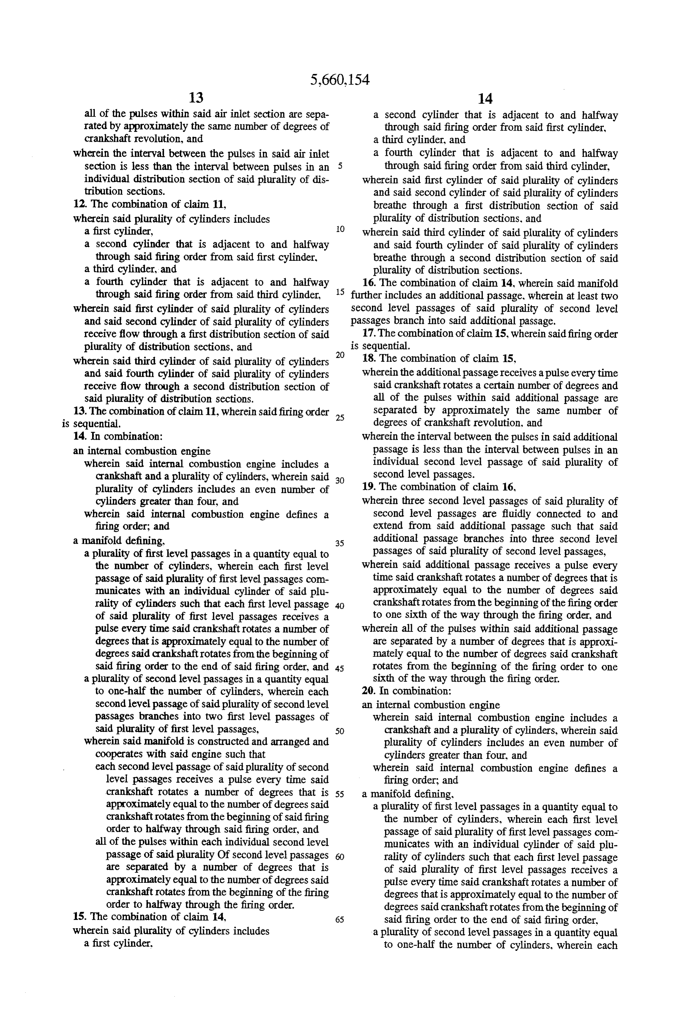
all of the pulses within said air inlet section are sepa a second cylinder that is adjacent to and halfway rated by approximately the same number of degrees of through said firing order from said first cylinder, crankshaft revolution, and a third cylinder, and wherein the interval between the pulses in said air inlet a fourth cylinder that is adjacent to and halfway section is less than the interval between pulses in an through said firing order from said third cylinder, individual distribution section of said plurality of dis wherein said first cylinder of said plurality of cylinders tribution sections. and said second cylinder of said plurality of cylinders 12. The combination of claim 11, breathe through a first distribution section of said wherein said plurality of cylinders includes plurality of distribution sections, and a first cylinder, O wherein said third cylinder of said plurality of cylinders a second cylinder that is adjacent to and halfway and said fourth cylinder of said plurality of cylinders through said firing order from said first cylinder, breathe through a second distribution section of said a third cylinder, and plurality of distribution sections. a fourth cylinder that is adjacent to and halfway 16. The combination of claim 14, wherein said manifold through said firing order from said third cylinder, 15 further includes an additional passage, wherein at least two wherein said first cylinder of said plurality of cylinders second level passages of said plurality of second level and said second cylinder of said plurality of cylinders passages branch into said additional passage. receive flow through a first distribution section of said 17. The combination of claim 15, wherein said firing order plurality of distribution sections, and 20 is sequential.
wherein said third cylinder of said plurality of cylinders 18. The combination of claim 15, and said fourth cylinder of said plurality of cylinders wherein the additional passage receives a pulse every time receive flow through a second distribution section of said crankshaft rotates a certain number of degrees and said plurality of distribution sections. all of the pulses within said additional passage are 13. The combination of claim 11, wherein said firing order 25 separated by approximately the same number of is sequential. degrees of crankshaft revolution, and 14. In combination: wherein the interval between the pulses in said additional an internal combustion engine passage is less than the interval between pulses in an wherein said internal combustion engine includes a individual second level passage of said plurality of crankshaft and a plurality of cylinders, wherein said 30 second level passages.
plurality of cylinders includes an even number of 19. The combination of claim 16, cylinders greater than four, and wherein three second level passages of said plurality of wherein said internal combustion engine defines a second level passages are fluidly connected to and firing order; and extend from said additional passage such that said a manifold defining. 35 additional passage branches into three second level a plurality of first level passages in a quantity equal to passages of said plurality of second level passages, the number of cylinders, wherein each first level wherein said additional passage receives a pulse every passage of said plurality of first level passages com time said crankshaft rotates a number of degrees that is municates with an individual cylinder of said plu approximately equal to the number of degrees said rality of cylinders such that each first level passage crankshaft rotates from the beginning of the firing order of said plurality of first level passages receives a to one sixth of the way through the firing order, and pulse every time said crankshaft rotates a number of wherein all of the pulses within said additional passage degrees that is approximately equal to the number of are separated by a number of degrees that is approxi degrees said crankshaft rotates from the beginning of mately equal to the number of degrees said crankshaft said firing order to the end of said firing order, and 45 rotates from the beginning of the firing order to one a plurality of second level passages in a quantity equal sixth of the way through the firing order. to one-half the number of cylinders, wherein each 20. In combination:
second level passage of said plurality of second level an internal combustion engine passages branches into two first level passages of wherein said internal combustion engine includes a said plurality of first level passages, 50 crankshaft and a plurality of cylinders, wherein said wherein said manifold is constructed and arranged and plurality of cylinders includes an even number of cooperates with said engine such that cylinders greater than four, and each second level passage of said plurality of second wherein said internal combustion engine defines a level passages receives a pulse every time said firing order; and crankshaft rotates a number of degrees that is 55 a manifold defining, approximately equal to the number of degrees said a plurality of first level passages in a quantity equal to crankshaft rotates from the beginning of said firing the number of cylinders, wherein each first level order to halfway through said firing order, and passage of said plurality of first level passages com all of the pulses within each individual second level municates with an individual cylinder of said plu passage of said plurality Of second level passages rality of cylinders such that each first level passage are separated by a number of degrees that is of said plurality of first level passages receives a approximately equal to the number of degrees said pulse every time said crankshaft rotates a number of crankshaft rotates from the beginning of the firing degrees that is approximately equal to the number of order to halfway through the firing order. degrees said crankshaft rotates from the beginning of 15. The combination of claim 14, 65 said firing order to the end of said firing order, wherein said plurality of cylinders includes a plurality of second level passages in a quantity equal a first cylinder. to one-half the number of cylinders, wherein each
Page 18
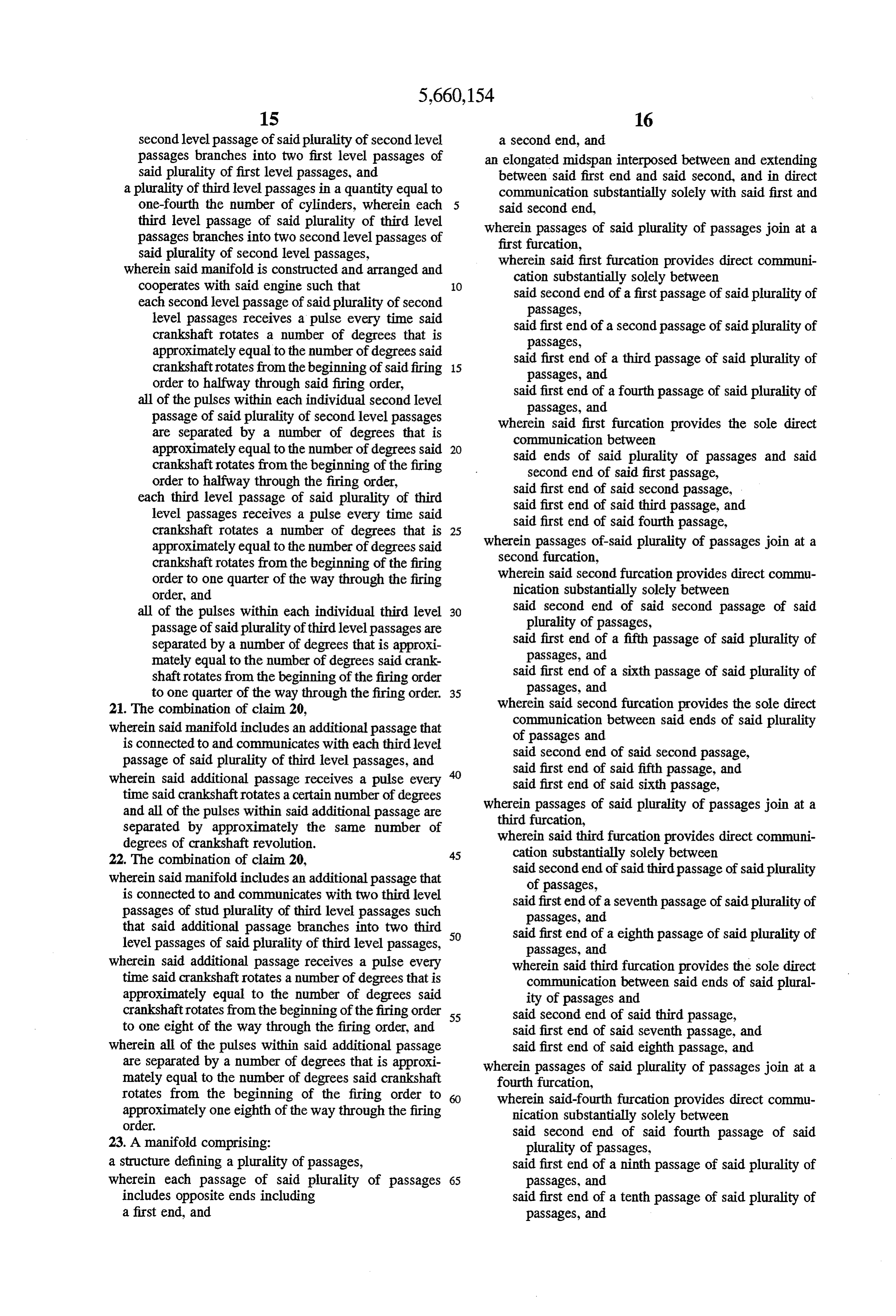
second level passage of said plurality of second level a second end, and passages branches into two first level passages of an elongated midspan interposed between and extending said plurality of first level passages, and between said first end and said second, and in direct a plurality of third level passages in a quantity equal to communication substantially solely with said first and one-fourth the number of cylinders, wherein each said second end, third level passage of said plurality of third level wherein passages of said plurality of passages join at a passages branches into two second level passages of first furcation, said plurality of second level passages, wherein said first furcation provides direct communi wherein said manifold is constructed and arranged and cation substantially solely between cooperates with said engine such that 10 said second end of a first passage of said plurality of each second level passage of said plurality of second passages, level passages receives a pulse every time said said first end of a second passage of said plurality of crankshaft rotates a number of degrees that is passages, approximately equal to the number of degrees said said first end of a third passage of said plurality of crankshaft rotates from the beginning of said firing 15 passages, and order to halfway through said firing order, said first end of a fourth passage of said plurality of all of the pulses within each individual second level passages, and passage of said plurality of second level passages wherein said first furcation provides the sole direct are separated by a number of degrees that is communication between approximately equal to the number of degrees said 20 said ends of said plurality of passages and said crankshaft rotates from the beginning of the firing second end of said first passage, order to halfway through the firing order, said first end of said second passage, each third level passage of said plurality of third said first end of said third passage, and level passages receives a pulse every time said said first end of said fourth passage, crankshaft rotates a number of degrees that is 25 wherein passages of said plurality of passages join at a approximately equal to the number of degrees said crankshaft rotates from the beginning of the firing second furcation, order to one quarter of the way through the firing wherein said second furcation provides direct commu order, and nication substantially solely between all of the pulses within each individual third level 30 said second end of said second passage of said passage of said plurality of third level passages are plurality of passages, separated by a number of degrees that is approxi said first end of a fifth passage of said plurality of mately equal to the number of degrees said crank passages, and shaft rotates from the beginning of the firing order said first end of a sixth passage of said plurality of to one quarter of the way through the firing order. 35 passages, and 21. The combination of claim 20, wherein said second furcation provides the sole direct wherein said manifold includes an additional passage that communication between said ends of said plurality is connected to and communicates with each third level of passages and passage of said plurality of third level passages, and said second end of said second passage, wherein said additional passage receives a pulse every said first end of said fifth passage, and said first end of said sixth passage, time said crankshaft rotates a certain number of degrees wherein passages of said plurality of passages join at a and all of the pulses within said additional passage are third furcation, separated by approximately the same number of wherein said third furcation provides direct communi degrees of crankshaft revolution. 45 cation substantially solely between 22. The combination of claim 20, said second end of said third passage of said plurality wherein said manifold includes an additional passage that of passages, is connected to and communicates with two third level passages of stud plurality of third level passages such said first end of a seventh passage of said plurality of passages, and that said additional passage branches into two third 50 said first end of a eighth passage of said plurality of level passages of said plurality of third level passages, passages, and wherein said additional passage receives a pulse every wherein said third furcation provides the sole direct time said crankshaft rotates a number of degrees that is communication between said ends of said plural approximately equal to the number of degrees said ity of passages and crankshaft rotates from the beginning of the firing order 55 said second end of said third passage, to one eight of the way through the firing order, and said first end of said seventh passage, and wherein all of the pulses within said additional passage said first end of said eighth passage, and are separated by a number of degrees that is approxi wherein passages of said plurality of passages join at a mately equal to the number of degrees said crankshaft fourth furcation, rotates from the beginning of the firing order to wherein said-fourth furcation provides direct commu approximately one eighth of the way through the firing nication substantially solely between order.
23. A manifold comprising: said second end of said fourth passage of said plurality of passages, a structure defining a plurality of passages, said first end of a ninth passage of said plurality of wherein each passage of said plurality of passages 65 passages, and includes opposite ends including said first end of a tenth passage of said plurality of a first end, and passages, and
Page 19
wherein said fourth furcation provides the sole direct level passage of said plurality of second level passages communication between said ends of said plurality branches into two first level passages of said plurality of passages and of first level passages, said second end of said fourth passage. wherein said manifold is constructed and arranged such said first end of said ninth passage, and 5 that said first end of said tenth passage. each second level passage of said plurality of second 24. A manifold for a multi-cylinder internal combustion level passages receives a pulse every time the crank engine having a crankshaft and an even number of cylinders shaft rotates a number of degrees that is approxi greater than four, and defining a firing order, the manifold mately equal to the number of degrees the crankshaft defining: 10 rotates from the beginning of the firing order to a plurality of first level passages in a quantity equal to the halfway through the firing order, and number of cylinders, wherein each first level passage of all of the pulses within each individual second level said plurality of first level passages is for communi passage of said plurality of second level passages are cating with an individual cylinder of the plurality of separated by a number of degrees that is approxi cylinders such that each first level passage of said 15 mately equal to the number of degrees the crankshaft plurality of first level passages receives a pulse every rotates from the beginning of the firing order to time the crankshaft rotates a number of degrees that is halfway through the firing order. approximately equal to the number of degrees the 25. The manifold of claim24, wherein each of said second crankshaft rotates from the beginning of the firing order level passages of said plurality of second level passages are to the end of the firing order, and '' interconnected.
a plurality of second level passages in a quantity equal to one-half the number of cylinders, wherein each second ck :: *k k :
Provenance
- Collection
- Cited prior art
- Original PDF
- patentimages.storage.googleapis.com →
- Filed
- 1994-08-09
- Pages
- 19
- Method
- pdftotext (the PDF's own text layer) + pdftoppm 300dpi page scans
- Source
- Google Patents bibliographic record
- Granted
- 1997-08-26
- Inventors
- Martin C. Fields
- Transcribed from
- patentimages.storage.googleapis.com →