patent · US5209191
Air intake manifold for an internal combustion engine
11 May 1993
Page 1 — bibliographic record
United States Patent (19. 11 Patent Number: 5,209,191 Kopec (45) Date of Patent: May 11, 1993 54 AIR INTAKE MANIFOLD FOR AN 5,014,654 5/1991 ashibashi ...................... 123/52 MC
NTERNAL COMBUSTON ENGINE
FOREIGN PATENT DOCUMENTS
75) Inventor: Eduard Kopec, Bietigheim-Bissingen, 251159 1/1988 European Pat. Off. . Fed. Rep. of Germany 2.822409 6/1984 Fed. Rep. of Germany . (73) Assignee: Filterwerk Mann & Hummel GmbH, 0075531 6/1980 Japan ............................. 123/52 MB Ludwigsburg, Fed. Rep. of Germany 2-37104 2/1990 Japan.
(21) Appl. No.: 800,361 Primary Examiner-David A. Okonsky 22 Filed: Dec. 3, 1991 Attorney, Agent, or Firm-Foley & Lardner 30 Foreign Application Priority Data 57 ABSTRAC Dec. 3, 1990 (DE) Fed. Rep. of Germany ....... 40.38509 An air intake manifold for an internal combustion en 51) Int. Cl. ............................................. FO2M 35/10 gine including a mounting flange through which a plu 52 U.S. C. ............................... 123/52 MC; 123/572 rality of intake ducts open. Blow-by gases from the 58) Field of Search .............. 123/572, 52 M., 52 MV, crankcase of the engine are introduced into the intake 123/52 MB, 52 MC ducts through channels or passageways communicating with the ducts adjacent a face of the mounting flange (56) References Cited which is fastened to the cylinder head of the engine.
blow-by gases are introduced into the channels or pas 3,505,983 4/1970 Hartel ............................ 123/52 MB sageways. The invention provides a simple design for 4,262,639 4/1981 Motosugi et al. . ... 123/52 MB feeding blow-by gases into the air intake manifold and 4,715,329 12/1987 Yasuda et al. ...................... 23/572 for assuring uniform filling of the individual intake 4,811,697 3/1989 Kurahashi..... ... 123/572 4,862,860 9/1989 Shinohara ........................... 123/572 ducts with blow-by gases which lubricate the intake 4,947,812 8/1990 Inoue et al. ......................... 123/572 valves due to their slight oil content. 4,958,613 9/1990 Hiraoka et al. ..................... 123/572 4,981,115 1/1991 Okasako et al. .............. 123/52 MV 6 Claims, 4 Drawing Sheets
Page 2
Drawing sheet — no readable text.
Page 3
Drawing sheet — no readable text.
Page 4
Drawing sheet — no readable text.
Page 5
Drawing sheet — no readable text.
Page 6
gases, uniformly to the individual intake ducts of the
AIR INTAKE MANIFOLD FOR AN INTERNAL engine.
COMBUSTION ENGINE It is also an object of the invention to provide an air intake manifold which can be manufactured in a simple
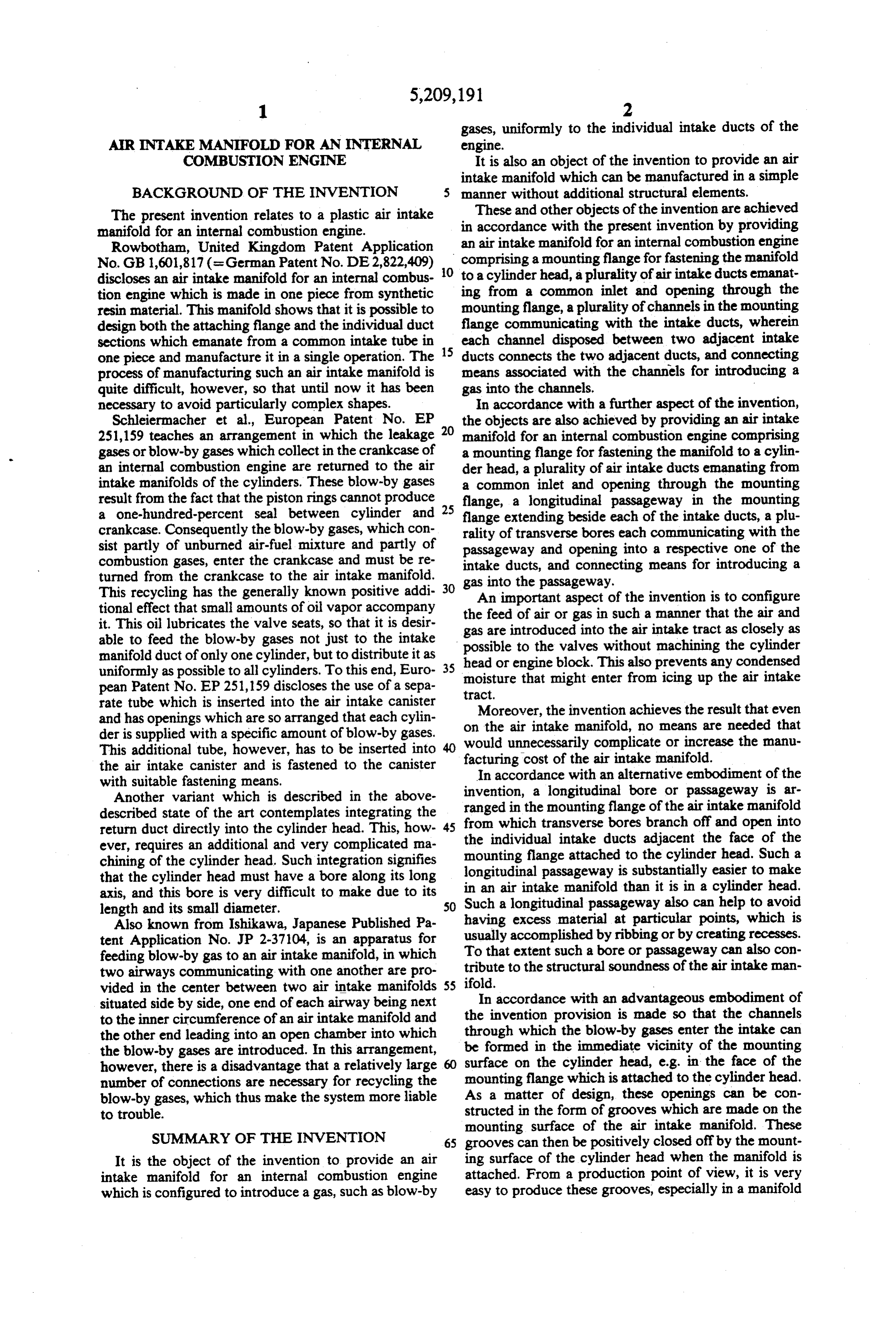
BACKGROUND OF THE INVENTION 5 manner without additional structural elements. The present invention relates to a plastic air intake in These and other objects of the invention are achieved accordance with the present invention by providing manifold for an internal combustion engine.
Rowbotham, United Kingdom Patent Application an air intake manifold for an internal combustion engine No. GB 1,601,817 (= German Patent No. DE 2,822,409) O comprising a mounting flange for fastening the manifold discloses an air intake manifold for an internal combus to a cylinder head, a plurality of air intake ducts emanat tion engine which is made in one piece from synthetic ing from a common inlet and opening through the resin material. This manifold shows that it is possible to mounting flange, a plurality of channels in the mounting design both the attaching flange and the individual duct flange communicating with the intake ducts, wherein sections which emanate from a common intake tube in each channel disposed between two adjacent intake one piece and manufacture it in a single operation. The 15 ducts connects the two adjacent ducts, and connecting process of manufacturing such an air intake manifold is means associated with the channels for introducing a quite difficult, however, so that until now it has been gas into the channels.
necessary to avoid particularly complex shapes. In accordance with a further aspect of the invention, Schleiermacher et al., European Patent No. EP 20 the objects are also achieved by providing an air intake 251,159 teaches an arrangement in which the leakage manifold for an internal combustion engine comprising gases or blow-by gases which collect in the crankcase of a mounting flange for fastening the manifold to a cylin an internal combustion engine are returned to the air der head, a plurality of air intake ducts emanating from intake manifolds of the cylinders. These blow-by gases a common inlet and opening through the mounting result from the fact that the piston rings cannot produce flange, a longitudinal passageway in the mounting a one-hundred-percent seal between cylinder and 25 flange extending beside each of the intake ducts, a plu crankcase. Consequently the blow-by gases, which con rality of transverse bores each communicating with the sist partly of unburned air-fuel mixture and partly of passageway and opening into a respective one of the combustion gases, enter the crankcase and must be re intake ducts, and connecting means for introducing a turned from the crankcase to the air intake manifold.
This recycling has the generally known positive addi 30 gasAnintoimportantthe passageway.
tional effect that small amounts of oil vapor accompany the feed of air oraspect gas in of the invention is to configure such a manner that the air and it. This oil lubricates the valve seats, so that it is desir gas are introduced into the air intake tract as closely as able to feed the blow-by gases not just to the intake possible to the valves without machining the cylinder manifold duct of only one cylinder, but to distribute it as head or engine block. This also prevents uniformly as possible to all cylinders. To this end, Euro moisture that might enter from icing upany
the condensed air intake pean Patent No. EP251,159 discloses the use of a sepa tract.
rate tube which is inserted into the air intake canister and has openings which are so arranged that each cylin onMoreover, the invention achieves the result that even the air intake manifold, no means are needed that der is supplied with a specific amount of blow-by gases. would unnecessarily complicate or increase the manu This additional tube, however, has to be inserted into facturing cost of the air intake manifold. the air intake canister and is fastened to the canister with suitable fastening means. In accordance with an alternative embodiment of the Another variant which is described in the above invention, a longitudinal bore or passageway is ar described state of the art contemplates integrating the from ranged in the mounting flange of the air intake manifold return duct directly into the cylinder head. This, how 45 which transverse bores branch off and open into ever, requires an additional and very complicated ma the individual intake ducts adjacent the face of the chining of the cylinder head. Such integration signifies mounting flange attached to the cylinder head. Such a that the cylinder head must have a bore along its long longitudinal passageway is substantially easier to make axis, and this bore is very difficult to make due to its in an air intake manifold than it is in a cylinder head. length and its small diameter. 50 Such a longitudinal passageway also can help to avoid Also known from Ishikawa, Japanese Published Pa usually having excess material at particular points, which is tent Application No. JP 2-37104, is an apparatus for accomplished by ribbing or by creating recesses. feeding blow-by gas to an air intake manifold, in which tribute toextent
To that such a bore or passageway can also con the structural soundness of the air intake man two airways communicating with one another are pro vided in the center between two air intake manifolds 55 ifold.
situated side by side, one end of each airway being next In accordance with an advantageous embodiment of to the inner circumference of an air intake manifold and the invention provision is made so that the channels the other end leading into an open chamber into which through which the blow-by gases enter the intake can the blow-by gases are introduced. In this arrangement, be formed in the immediate vicinity of the mounting however, there is a disadvantage that a relatively large surface on the cylinder head, e.g. in the face of the number of connections are necessary for recycling the mounting flange which is attached to the cylinder head. blow-by gases, which thus make the system more liable As a matter of design, these openings can be con to trouble. structed in the form of grooves which are made on the mounting surface of the air intake manifold. These
SUMMARY OF THE INVENTION 65 grooves can then be positively closed off by the mount It is the object of the invention to provide an air ing surface of the cylinder head when the manifold is intake manifold for an internal combustion engine attached. From a production point of view, it is very which is configured to introduce a gas, such as blow-by easy to produce these grooves, especially in a manifold
Page 7
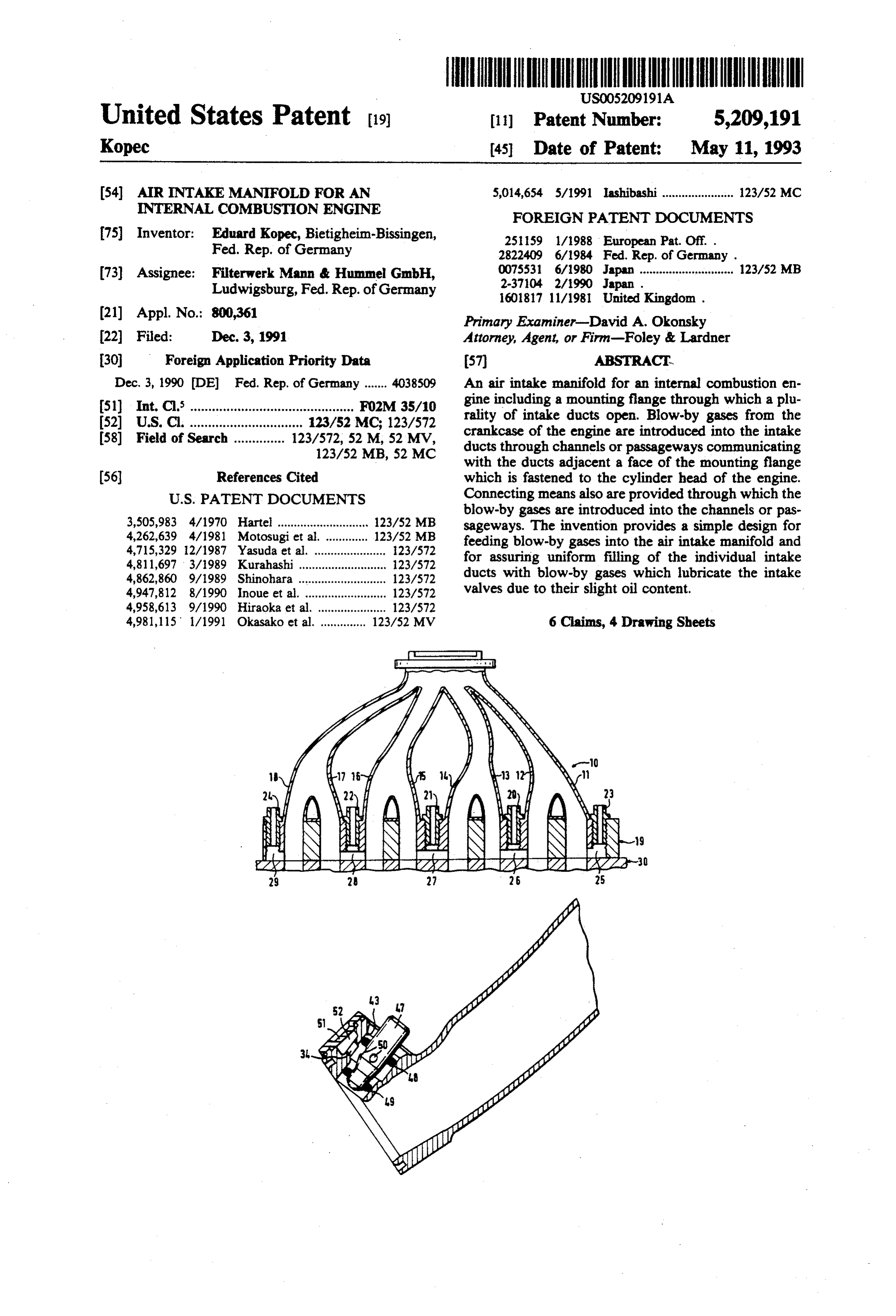
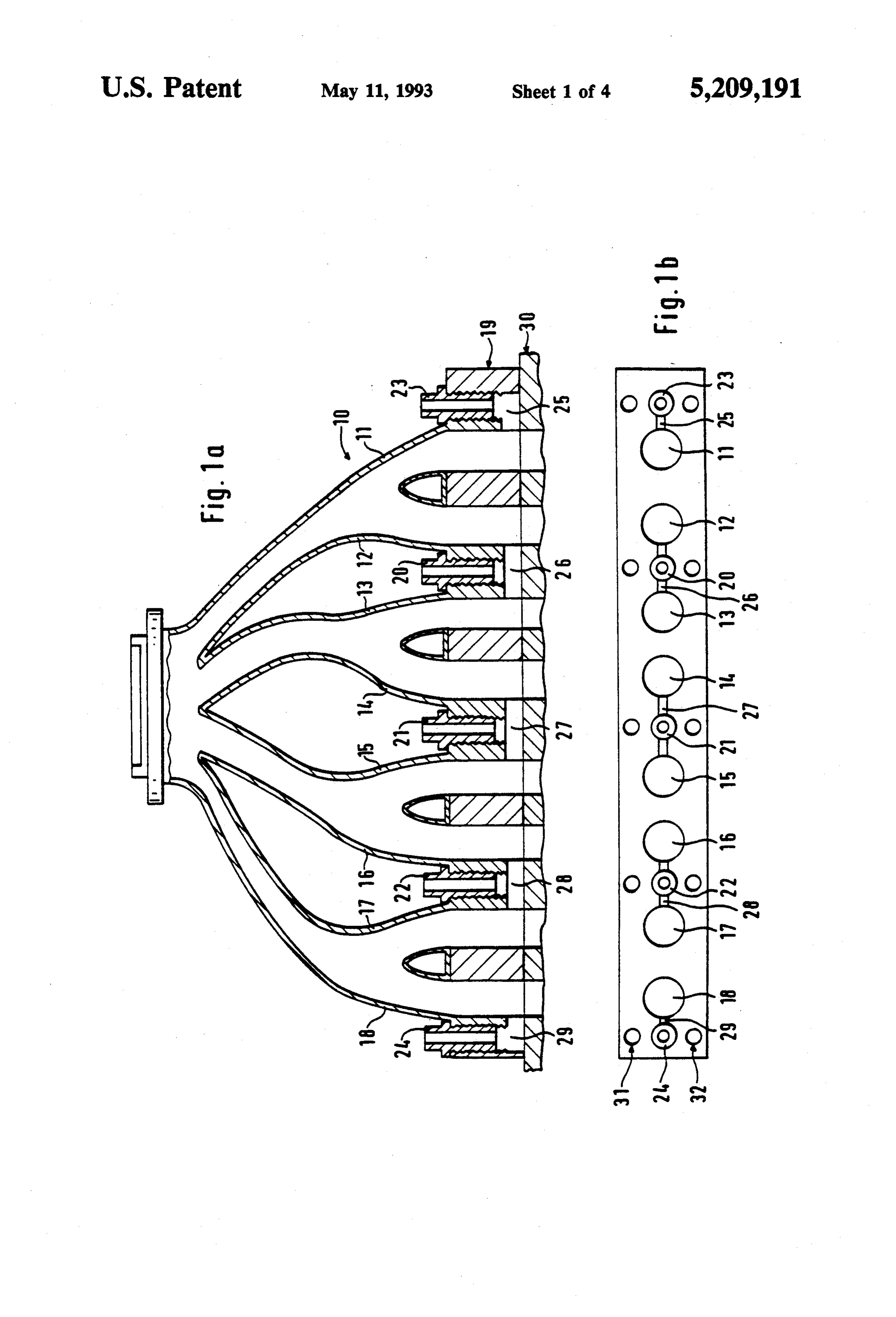
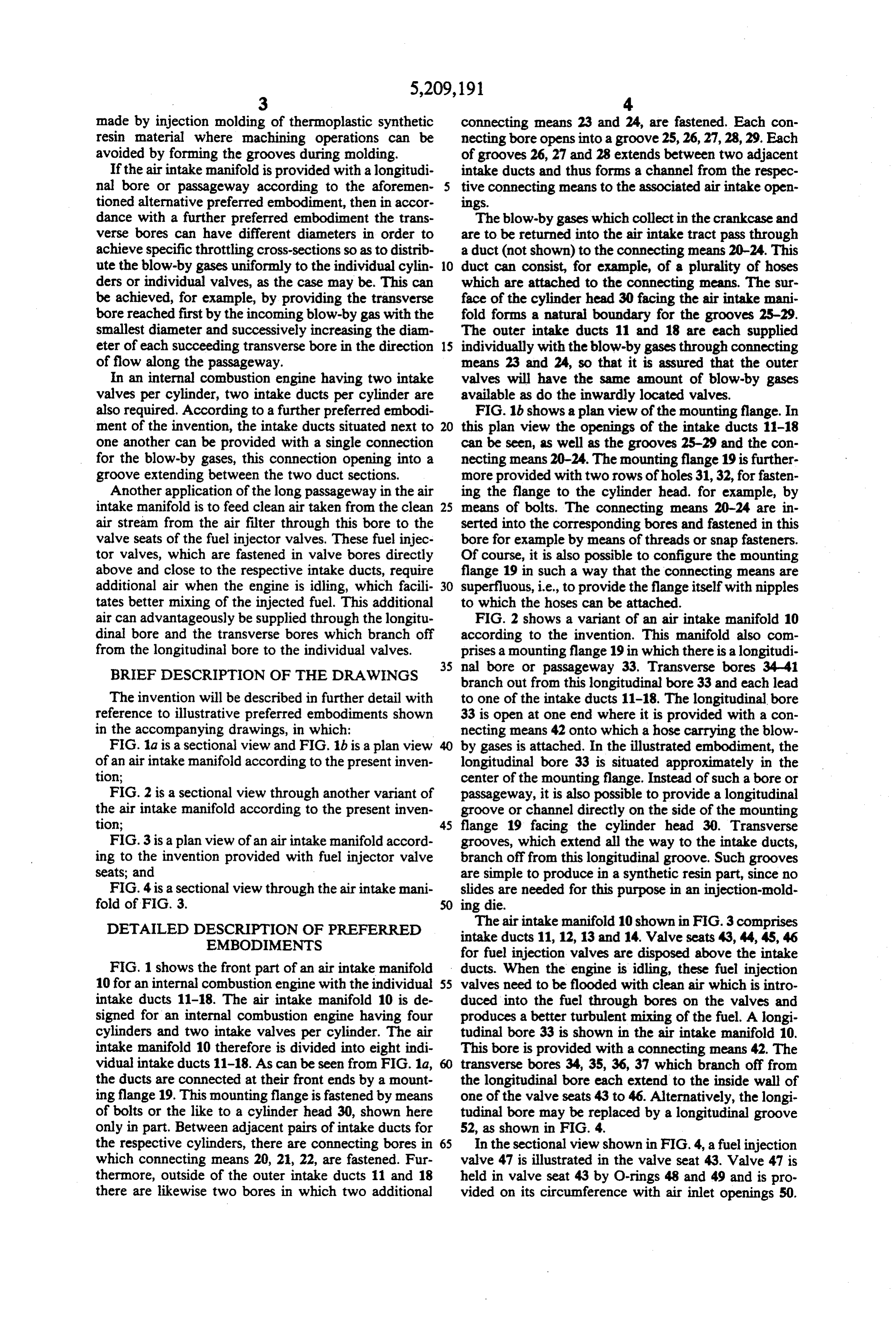
made by injection molding of thermoplastic synthetic connecting means 23 and 24, are fastened. Each con resin material where machining operations can be necting bore opens into a groove 25, 26, 27, 28, 29. Each avoided by forming the grooves during molding. of grooves 26, 27 and 28 extends between two adjacent If the air intake manifold is provided with a longitudi intake ducts and thus forms a channel from the respec nal bore or passageway according to the aforemen tive connecting means to the associated air intake open tioned alternative preferred embodiment, then in accor lings.
dance with a further preferred embodiment the trans The blow-by gases which collect in the crankcase and verse bores can have different diameters in order to are to be returned into the air intake tract pass through achieve specific throttling cross-sections so as to distrib a duct (not shown) to the connecting means 20-24. This ute the blow-by gases uniformly to the individual cylin 10 duct can consist, for example, of a plurality of hoses ders or individual valves, as the case may be. This can which are attached to the connecting means. The sur be achieved, for example, by providing the transverse face of the cylinder head 30 facing the air intake mani bore reached first by the incoming blow-by gas with the fold forms a natural boundary for the grooves 25-29. smallest diameter and successively increasing the diam The outer intake ducts 11 and 18 are each supplied eter of each succeeding transverse bore in the direction 15 individually with the blow-by gases through connecting of flow along the passageway. means 23 and 24, so that it is assured that the outer In an internal combustion engine having two intake valves will have the same amount of blow-by gases valves per cylinder, two intake ducts per cylinder are available as do the inwardly located valves. also required. According to a further preferred embodi FIG.1b shows a plan view of the mounting flange. In ment of the invention, the intake ducts situated next to 20 this plan view the openings of the intake ducts 11-18 one another can be provided with a single connection can be seen, as well as the grooves 25-29 and the con for the blow-by gases, this connection opening into a necting means 20-24. The mounting flange 19 is further groove extending between the two duct sections. more provided with two rows of holes 31, 32, for fasten Another application of the long passageway in the air ing the flange to the cylinder head. for example, by intake manifold is to feed clean air taken from the clean 25 means of bolts. The connecting means 20-24 are in air stream from the air filter through this bore to the serted into the corresponding bores and fastened in this valve seats of the fuel injector valves. These fuel injec bore for example by means of threads or snap fasteners. tor valves, which are fastened in valve bores directly Of course, it is also possible to configure the mounting above and close to the respective intake ducts, require flange 19 in such a way that the connecting means are additional air when the engine is idling, which facili 30 superfluous, i.e., to provide the flange itself with nipples tates better mixing of the injected fuel. This additional to which the hoses can be attached. air can advantageously be supplied through the longitu FIG. 2 shows a variant of an air intake manifold 10 dinal bore and the transverse bores which branch off according to the invention. This manifold also com from the longitudinal bore to the individual valves. prises a mounting flange 19 in which there is alongitudi 35 nal bore or passageway 33. Transverse bores 34-41
BRIEF DESCRIPTION OF THE DRAWINGS
branch out from this longitudinal bore 33 and each lead
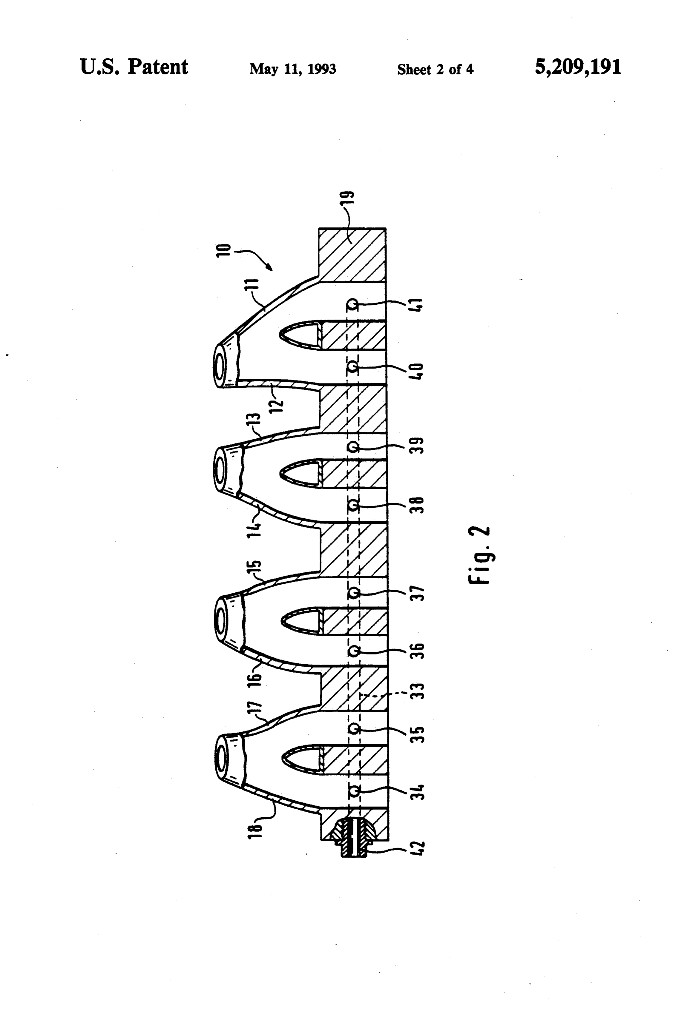
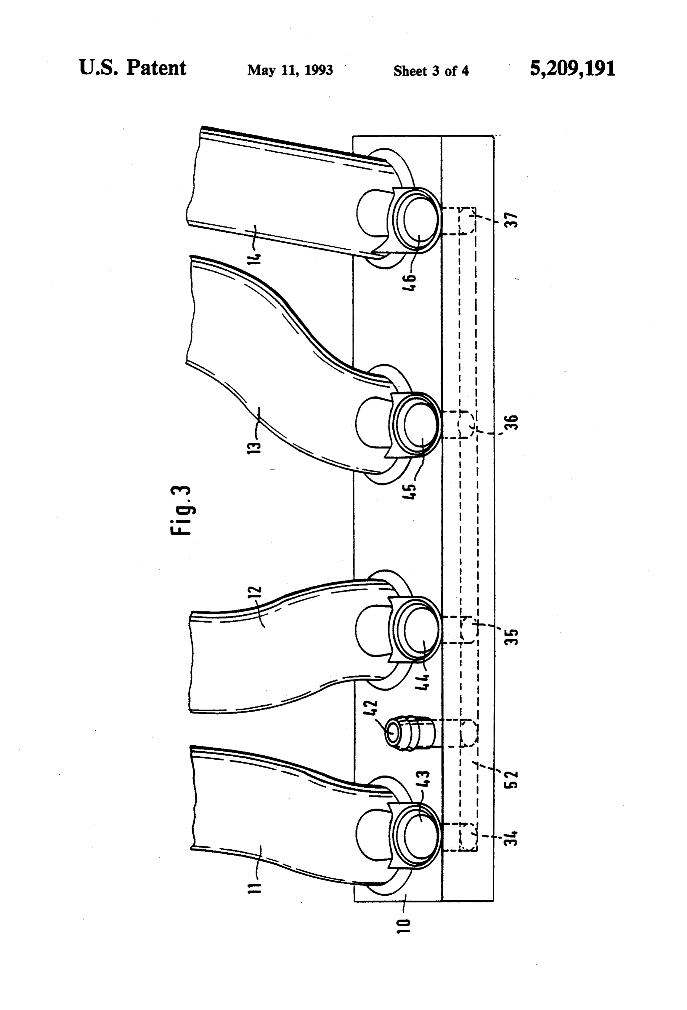
The invention will be described in further detail with to one of the intake ducts 11-18. The longitudinal bore reference to illustrative preferred embodiments shown 33 is open at one end where it is provided with a con in the accompanying drawings, in which: necting means 42 onto which a hose carrying the blow FIG. 1a is a sectional view and FIG. 1b is a plan view 40 by gases is attached. In the illustrated embodiment, the of an air intake manifold according to the present inven longitudinal bore 33 is situated approximately in the tion; center of the mounting flange. Instead of such a bore or FIG. 2 is a sectional view through another variant of passageway, it is also possible to provide a longitudinal the air intake manifold according to the present inven groove or channel directly on the side of the mounting tion; 45 flange 19 facing the cylinder head 30. Transverse FIG. 3 is a plan view of an air intake manifold accord grooves, which extend all the way to the intake ducts, ing to the invention provided with fuel injector valve branch off from this longitudinal groove. Such grooves seats; and are simple to produce in a synthetic resin part, since no FIG. 4 is a sectional view through the air intake mani slides are needed for this purpose in an injection-mold fold of FIG. 3. ing die.
DETALED DESCRIPTION OF PREFERRED The air intake manifold 10 shown in FIG. 3 comprises EMBODIMENTS intake ducts 11, 12, 13 and 14. Valve seats 43, 44, 4S, 46 for fuel injection valves are disposed above the intake
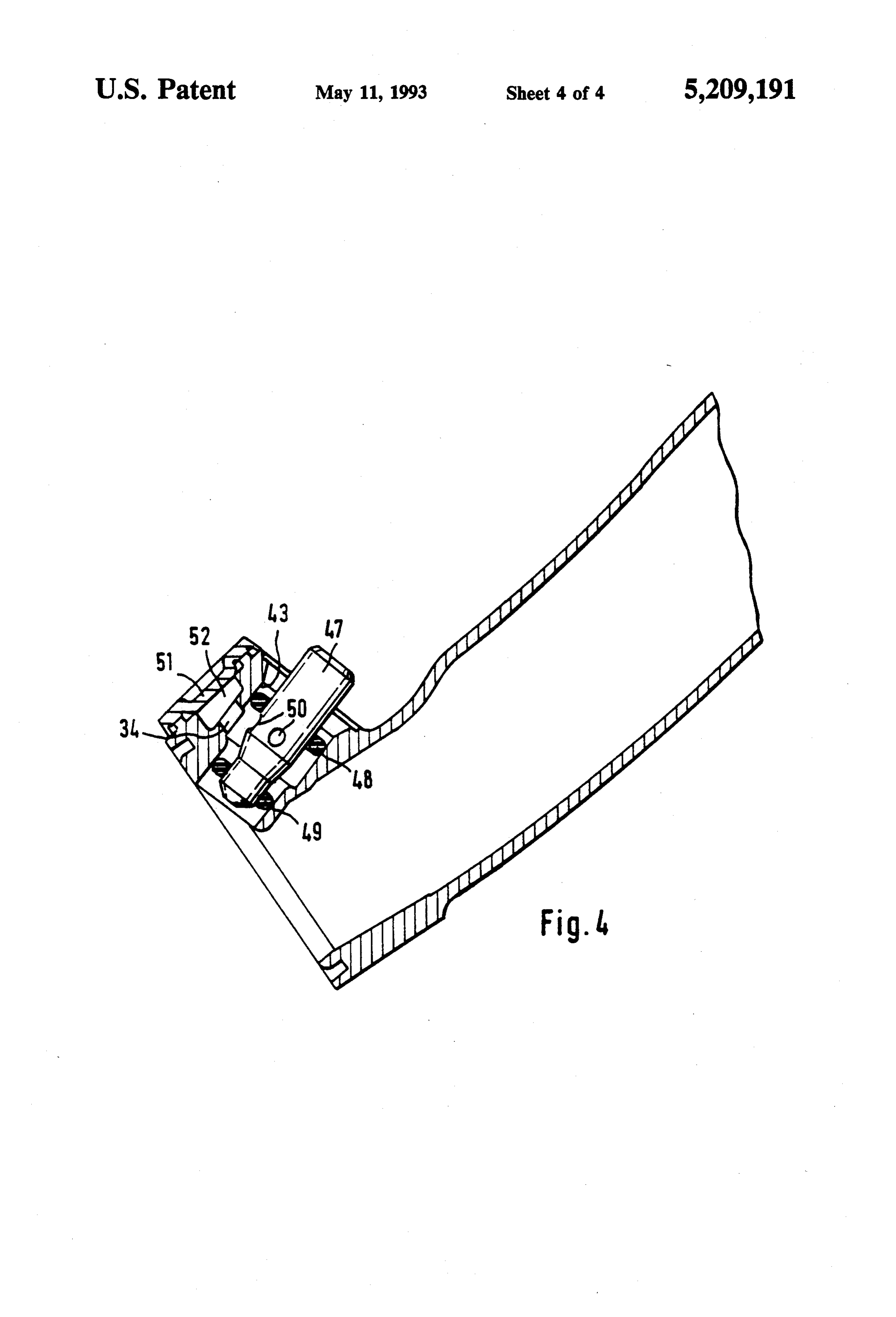
FIG. 1 shows the front part of an air intake manifold ducts. When the engine is idling, these fuel injection 10 for an internal combustion engine with the individual 55 valves need to be flooded with clean air which is intro intake ducts 11-18. The air intake manifold 10 is de duced into the fuel through bores on the valves and signed for an internal combustion engine having four produces a better turbulent mixing of the fuel. A longi cylinders and two intake valves per cylinder. The air tudinal bore 33 is shown in the air intake manifold 10. intake manifold 10 therefore is divided into eight indi This bore is provided with a connecting means 42. The vidual intake ducts 11-18. As can be seen from FIG. 1a, transverse bores 34, 35, 36, 37 which branch off from the ducts are connected at their front ends by a mount the longitudinal bore each extend to the inside wall of ing flange 19. This mounting flange is fastened by means one of the valve seats 43 to 46. Alternatively, the longi of bolts or the like to a cylinder head 30, shown here tudinal bore may be replaced by a longitudinal groove only in part. Between adjacent pairs of intake ducts for 52, as shown in FIG. 4.
the respective cylinders, there are connecting bores in 65 In the sectional view shown in FIG.4, a fuel injection which connecting means 20, 21, 22, are fastened. Fur valve 47 is illustrated in the valve seat 43. Valve 47 is thermore, outside of the outer intake ducts 11 and 18 held in valve seat 43 by O-rings 48 and 49 and is pro there are likewise two bores in which two additional vided on its circumference with air inlet openings 50.
Page 8
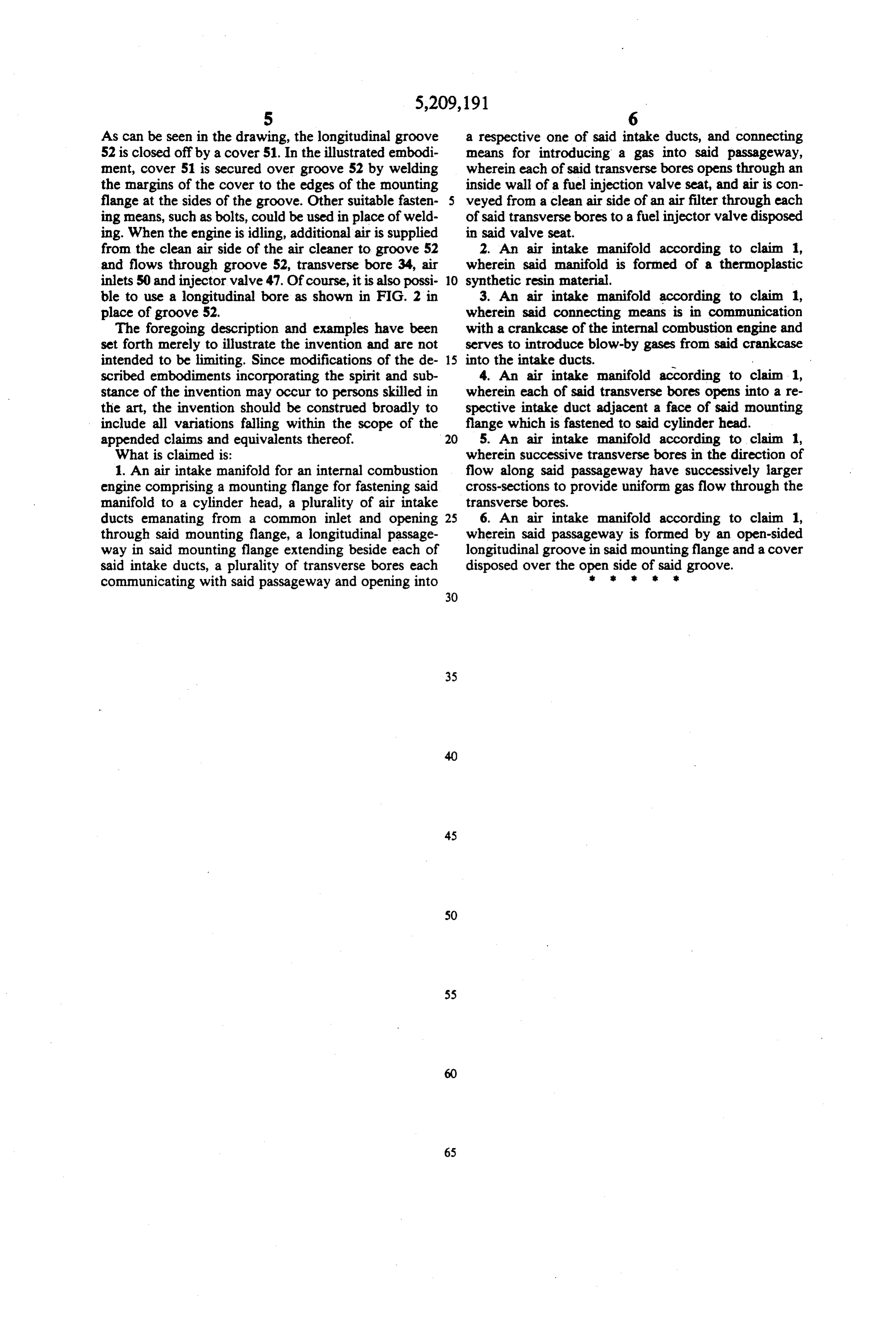
As can be seen in the drawing, the longitudinal groove a respective one of said intake ducts, and connecting 52 is closed off by a cover 51. In the illustrated embodi means for introducing a gas into said passageway, ment, cover 51 is secured over groove 52 by welding wherein each of said transverse bores opens through an the margins of the cover to the edges of the mounting inside wall of a fuel injection valve seat, and air is con flange at the sides of the groove. Other suitable fasten 5 veyed from a clean air side of an air filter through each ing means, such as bolts, could be used in place of weld of said transverse bores to a fuel injector valve disposed ing. When the engine is idling, additional air is supplied in said valve seat.
from the clean air side of the air cleaner to groove 52 2. An air intake manifold according to claim 1, and flows through groove 52, transverse bore 34, air wherein said manifold is formed of a thermoplastic inlets 50 and injector valve 47. Of course, it is also possi O synthetic resin material.
ble to use a longitudinal bore as shown in FIG. 2 in 3. An air intake manifold according to claim 1, place of groove 52. wherein said connecting means is in communication The foregoing description and examples have been with a crankcase of the internal combustion engine and set forth merely to illustrate the invention and are not serves to introduce blow-by gases from said crankcase intended to be limiting. Since modifications of the de 15 into the intake ducts. 1. scribed embodiments incorporating the spirit and sub 4. An air intake manifold according to claim 1, stance of the invention may occur to persons skilled in wherein each of said transverse bores opens into a re the art, the invention should be construed broadly to spective intake duct adjacent a face of said mounting include all variations falling within the scope of the flange which is fastened to said cylinder head. appended claims and equivalents thereof. 20 5. An air intake manifold according to claim 1, What is claimed is: wherein successive transverse bores in the direction of 1. An air intake manifold for an internal combustion flow along said passageway have successively larger engine comprising a mounting flange for fastening said cross-sections to provide uniform gas flow through the manifold to a cylinder head, a plurality of air intake transverse bores.
ducts emanating from a common inlet and opening 25 6. An air intake manifold according to claim 1, through said mounting flange, a longitudinal passage wherein said passageway is formed by an open-sided way in said mounting flange extending beside each of longitudinal groove in said mounting flange and a cover said intake ducts, a plurality of transverse bores each disposed over the open side of said groove. communicating with said passageway and opening into
Provenance
- Collection
- Cited prior art
- Original PDF
- patentimages.storage.googleapis.com →
- Filed
- 1991-12-03
- Pages
- 8
- Method
- pdftotext (the PDF's own text layer) + pdftoppm 300dpi page scans
- Source
- Google Patents bibliographic record
- Granted
- 1993-05-11
- Inventors
- Eduard Kopec; Filterwerk Mann and Hummel GmbH
- Transcribed from
- patentimages.storage.googleapis.com →