patent · US5515822
Intake system
14 May 1996
Page 1 — bibliographic record
United States Patent (19) 11 Patent Number: 5,515,822
Kobayashi et al. (45) Date of Patent: May 14, 1996 54 INTAKE SYSTEM 5,127,370 7/1992 Suzuki et al. ........................... 123,432 75 Inventors: Manabu Kobayashi, Akira FOREIGN PATENT DOCUMENTS Yamaguchi, both of Iwata, Japan 0223373 5/1987 European Pat. Off. .......... 123/84.31 4014291 11/1991 Germany ............ ... 123/184.35 73) Assignee: Yamaha Hatsudoki Kabushiki Kaisha, 60-222523 11/1985 Japan ...... ... 123/184.42 Iwata, Japan 3-9024 1/1991 Japan ...... ... 123,184.31 4-164121 6/1992 Japan ................................ 123/18431 (21) Appl. No. 245,968 Primary Examiner-David A. Okonsky
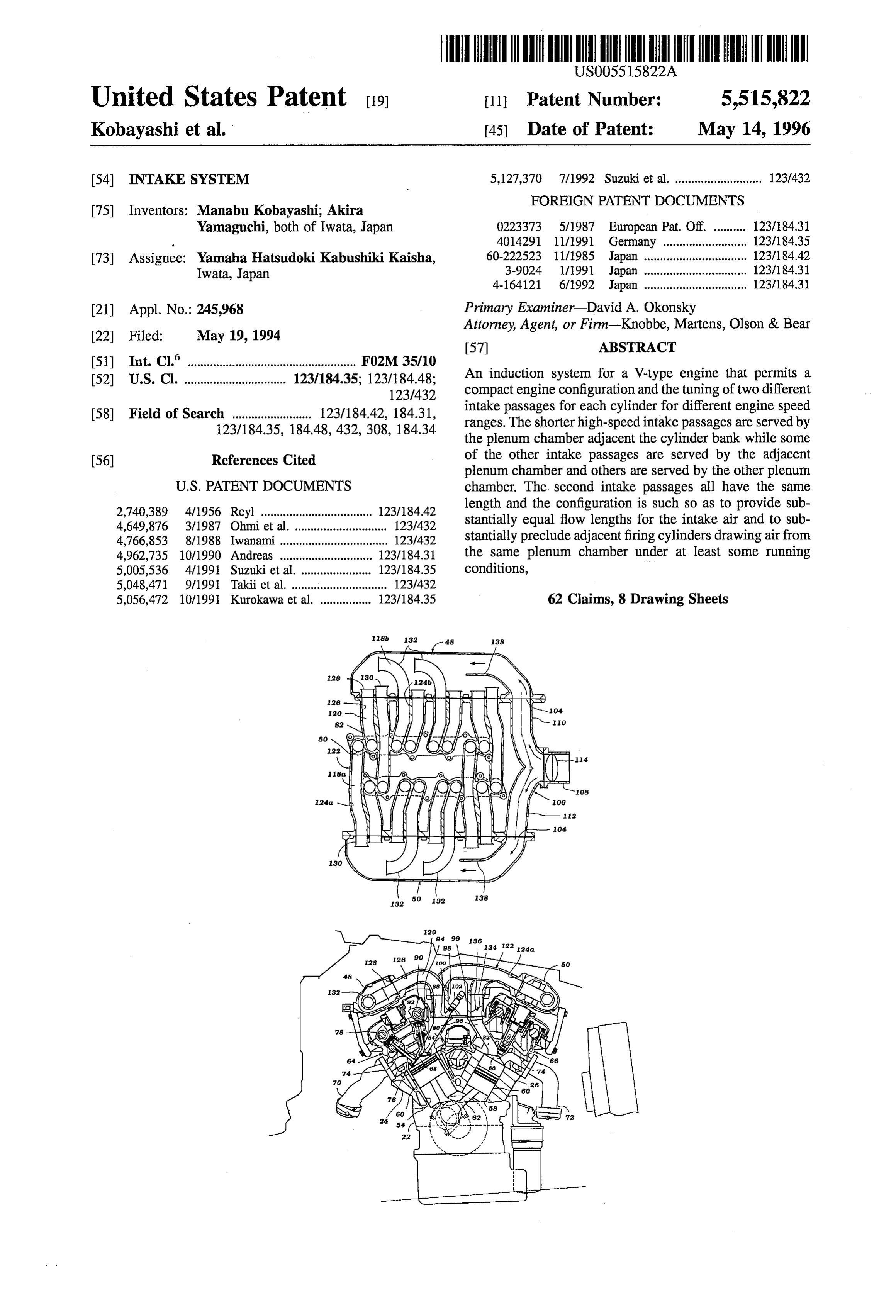
19, 1994 Attorney, Agent, or Firm-Knobbe, Martens, Olson & Bear y 9, 57) ABSTRACT (51) Int. Cl." ...................................... F02M 35/10 (52) U.S. Cl. ................................ 123/18435, 123/18448. An induction system for a V-type engine that permits a 1231433 compact engine configuration and the tuning of two different 58) Field of Search 123/18442, 184.31 intake passages for each cylinder for different engine speed ranges. The shorter high-speed intake passages are served by 123/184.35, 18448, 432, 308, 184.34 the plenum chamber adjacent the cylinder bank while some (56) References Cited of the other intake passages are served by the adjacent plenum chamber and others are served by the other plenum
2,740,389 4/1956 Reyl ...... 123/184.42 length and the configuration is such so as to provide sub 4649876 3/1987 Olimetal.". E, stantially equal flow lengths for the intake air and to sub 4766,853 8/1988 Iwanami. 123,432 stantially preclude adjacent firing cylinders drawing air from 4,962,735 10/1990 Andreas ............................. 123/18431 the same plenum chamber under at least Some running 5,005,536 4/1991 Suzuki et al... 123/18435 conditions, 5,048,471 9/1991 Taki et al. .............................. 123,432 5,056,472 10/1991 Kurokawa et al. ................ 123/18435 62 Claims, 8 Drawing Sheets
Page 2
Drawing sheet — no readable text.
Page 3
Drawing sheet — no readable text.
Page 4
Drawing sheet — no readable text.
Page 5
Drawing sheet — no readable text.
Page 6
Drawing sheet — no readable text.
Page 7
Drawing sheet — no readable text.
Page 8
Drawing sheet — no readable text.
Page 9
Drawing sheet — no readable text.
Page 10
INTAKE SYSTEM Such an arrangement is facilitated when each cylinder has both of its intake passages served by a different plenum
BACKGROUND OF THE INVENTION chamber. However, when one plenum chamber may serve both intake passages of the same cylinder, then it is more
This invention relates to an intake system and more difficult to ensure that no two cylinders will draw succes particularly to an improved induction system for an internal sively from the same plenum chamber. combustion engine. It is, therefore, a still further object of this invention to As is well known, the induction system of an internal provide an improved induction system for an internal com combustion engine is extremely important in determining bustion engine having a pair of plenum chambers that serve the performance of the engine. Since in many applications, 10 a multitude of cylinders and wherein the charge is not drawn particularly for use in motor vehicles, the engine is required from one plenum chamber on successive firings of the to run over widely varying speed and load ranges, it has been engine under at least certain running conditions. proposed to provide an induction system wherein each As will be noted from the aforenoted United States Letters cylinder of the engine is served by a pair of intake passages Patents, the system can be simplified if there is a single each of which is tuned for a different running condition of 5 atmospheric air inlet that serves both plenum chambers. This the engine. Such an arrangement is shown in U.S. Pat. No. eliminates the necessity for separate air cleaner, silencer 4,649,876, entitled "Intake Means of Internal Combustion assemblies for each plenum chamber and also permits the Engine,” issued Mar. 17, 1987 in the names of Masatoshi use of a single main throttle valve positioned in the common Ohmi, et al., which patent is assigned to the assignee hereof. air inlet. However, this generally requires the inlets to the That induction system is particularly designed for use with 20 respective plenum chambers to be located at one end of the V-type engines and includes a pair of plenum chambers each engine so as to reduce height and avoid additional complex disposed in proximity to one of the cylinder banks. The two ity of the intake plumbing. However, when the air is intake passages for each cylinder are served respectively by introduced into the plenum chamber at one of its ends, then one of the plenum chambers so as to provide a short different air flow lengths occur between the inlet and the high-speed intake passage from the adjacent plenum cham 25 various cylinders served by them. This can cause some ber and a longer low-speed intake passage from the plenum cylinder to cylinder variation.
chamber associated with the opposite cylinder bank. This It is, therefore, a still further object of this invention to arrangement provides extremely good engine performance.
provide an improved induction system for a plenum cham
However, the arrangement used therein requires a number ber that serves a multiple number of cylinders and which has of intake passages that extend across the valley between the 30 its inlet at one end but which minimizes the difference of the cylinder banks to the opposite plenum chambers. This adds flow lengths between the inlet and the individual cylinders significantly to the external plumbing of the engine. In served thereby.
addition, this type of induction system generally increases The problem of maintaining a low hoodline has already the height requirements of the engine, not always a desirable been mentioned in conjunction with induction systems of result. 35 this type. By positioning the plenum chambers over the
It is, therefore, a principal object of this invention to cylinder heads of the engine, the height of the induction provide an improved induction system for an engine that system is increased. Where the engine is positioned trans permits tuning of the cylinder to two different speed ranges versely in the engine compartment, a common practice with while at the same time maintaining a minimum amount of 40 certain types of vehicles such as front engine, front wheel external plumbing and a low height. drive or rear engine, rear wheel drive vehicles, the desire of The amount of external conduitry required can be sim providing a sloping hood can be complicated by this type of plified if not all cylinders of each cylinder bank are served induction system.
by the plenum chambers of both cylinder banks. However, It is, therefore, a still further object of this invention to if one plenum chamber serves both intake passages for the 45 provide an induction system of this type which maintains a cylinder of the associated cylinder bank, it is somewhat low engine profile and permits a low sloping hood. more difficult to provide the different flow lengths to provide the different tuning. SUMMARY OF THE INVENTION It is, therefore, a further object of this invention to provide an improved induction system for an engine having cylinder 50 A first feature of this invention is adapted to be embodied banks which reduces the number of external conduits but in an induction system for an internal combustion engine which permits independent tuning of two intake passages for having a pair of angularly disposed cylinder banks each each cylinder. having at least two cylinders. First and second plenum If both intake passages of a given cylinder are served by chambers are provide each of which is juxtaposed to a an adjacent plenum chamber or, for that matter, by a plenum 55 respective one of the cylinder banks. A first series of intake chamber disposed on the opposite side of the engine, then a passages each extend from one of the cylinders to the situation may arise wherein the intake pulses from one adjacent plenum chamber. A second series of intake pas cylinder adversely effect those of other cylinders. In U.S. sages extend from a first number of the cylinders to the Pat. No. 4,809,647, entitled “Intake System for Multi adjacent plenum chamber and a third series of intake pas Cylindered Engine,' issued Mar. 7, 1989 in the name of 60 sages extend from the remaining of the cylinders to the Iwao Matsumoto, et al., assigned to the assignee hereof, non-adjacent plenum chamber.
there is disclosed an arrangement wherein the cylinders of Another feature of the invention is also adapted to be the engine fire in an order so that no two cylinders will draw embodied in an induction system for an internal combustion from the same plenum chamber on successive firings. This engine and in which the engine has a plurality of aligned improves the performance of the engine because it ensures 65 cylinders. A plenum chamber having an atmospheric inlet at that adequate air will be available in each plenum chamber one end thereof is provided and a plurality of intake passages to serve the cylinders. extend from the cylinders into the plenum chamber and open
Page 11
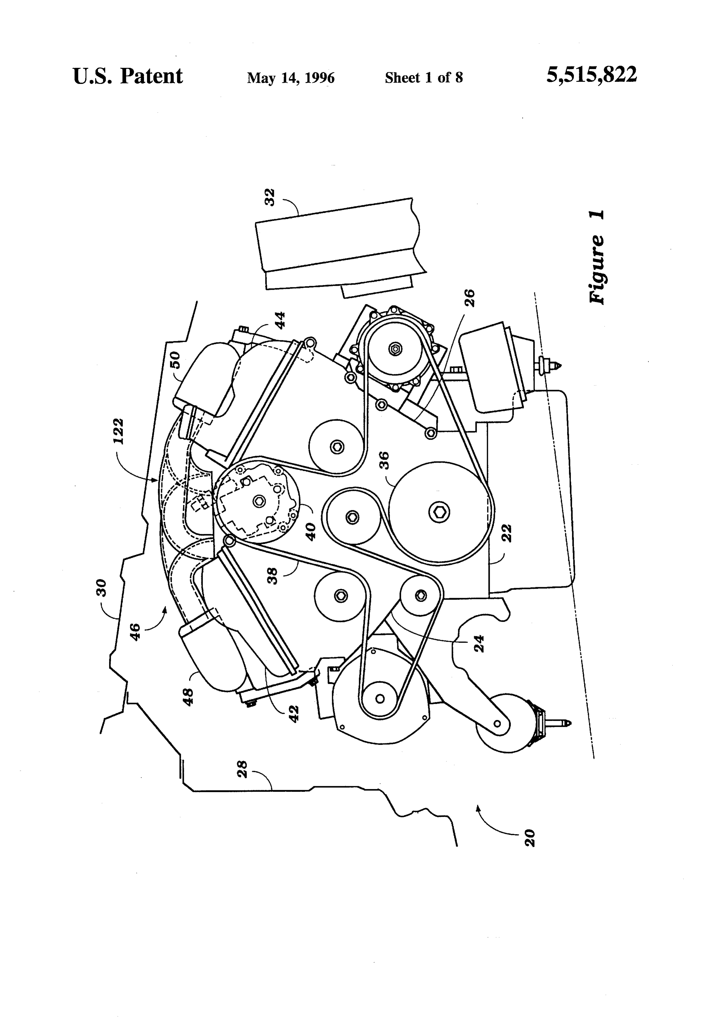
therein at positions spaced along the length of the plenum radiator 32, situated adjacent the engine 20, is located at the chamber. Means form an internal duct in the plenum cham forward end of the vehicle in which the engine is situated. ber from the atmospheric air inlet to a point in the plenum Within the engine block 22, the engine journals a crankshaft chamber substantially at the center of the intake passages. on which a flywheel 34 (FIG. 2) and a drive pulley 36 (FIG. A further feature of the invention is adapted to be embod 1) are keyed. One or more belts 38 extend around the drive ied in an induction system for a V-type engine having a pair pulley 36 and around a plurality of engine pulleys, one of which being a fuel pump pulley 40, described in more detail of cylinder banks that are disposed at a V angle to each other.
The cylinder banks each have cam covers associated there below. mounted
A pair of angled cam covers 42, 44 are sealingly on a top surface of each cylinder bank 24, 26. The with with the upper surfaces of the cam covers lying at acute cam covers 42, 44 generally lie perpendicular to outwardly angles to a horizontal plane perpendicular to a vertical plane diverging lines
through each cylinder bank 24, 26. Because bisecting the cylinder banks. A pair of plenum chambers of this arrangement, if the engine 20 is oriented so that each each extend along the upper surface of a respective one of cylinder bank 24, 26 makes a 30-degree angle with a central the cam covers and have lower surfaces that extend sub bisecting vertical plane, each cam cover 42, 44 makes stantially parallel to the upper surfaces of the cam covers for approximately a 30-degree angle with a horizontal plane. maintaining a low profile of the engine. Intake passages 15 With reference to FIGS. 1-3, the present internal com extend from the cylinders into the plenum chambers for bustion engine 20 incorporates an improved air intake delivering a charge to the cylinders. induction system 46 mounted atop the engine. The induction system 46 generally comprises a pair of plenum chambers
BRIEF DESCRIPTION OF THE DRAWINGS 48,50 juxtaposed above each cylinder bank 24, 26, respec
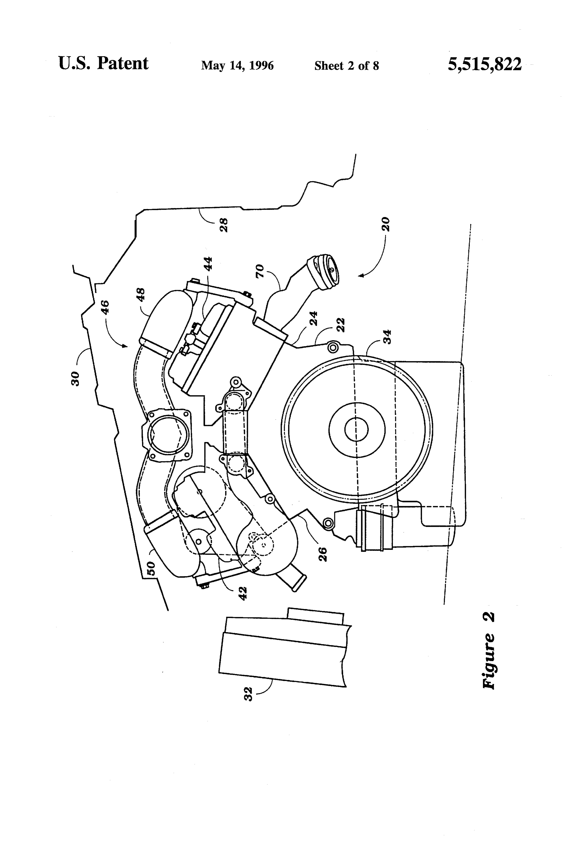
FIG. 1 is a front elevational view of an internal combus tively, and a plurality of intake passages, as will be described tion engine constructed in accordance with an embodiment below. The induction system 46 generally functions to of the present invention; provide a correct airflow to the combustion chambers within FIG. 2 is a rear elevational view of the internal combus the eight cylinders of the engine. The improved design of the tion engine of FIG. 1; 25 induction system 46 allows the associated intake conduit plumbing to be reduced in profile, and thus allows the entire
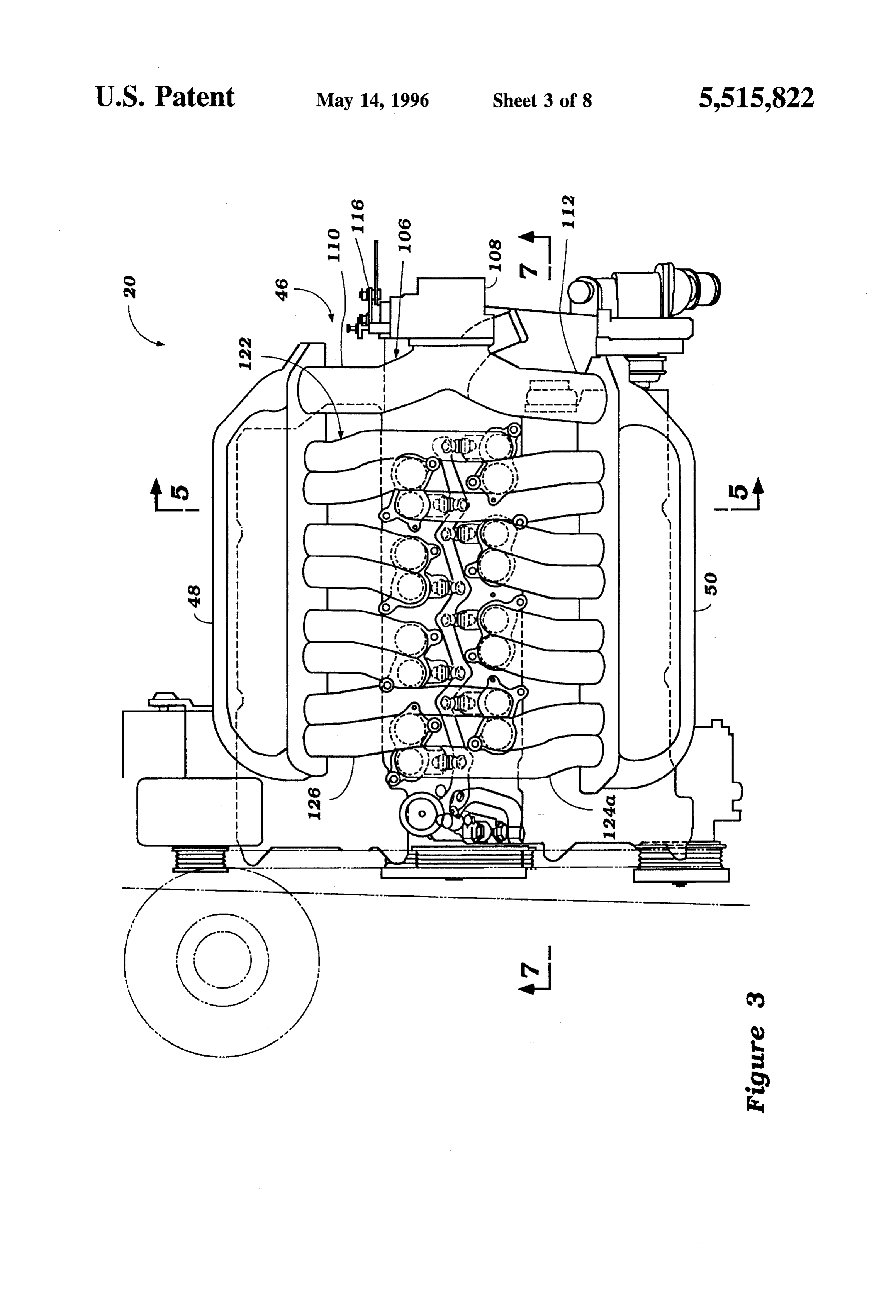
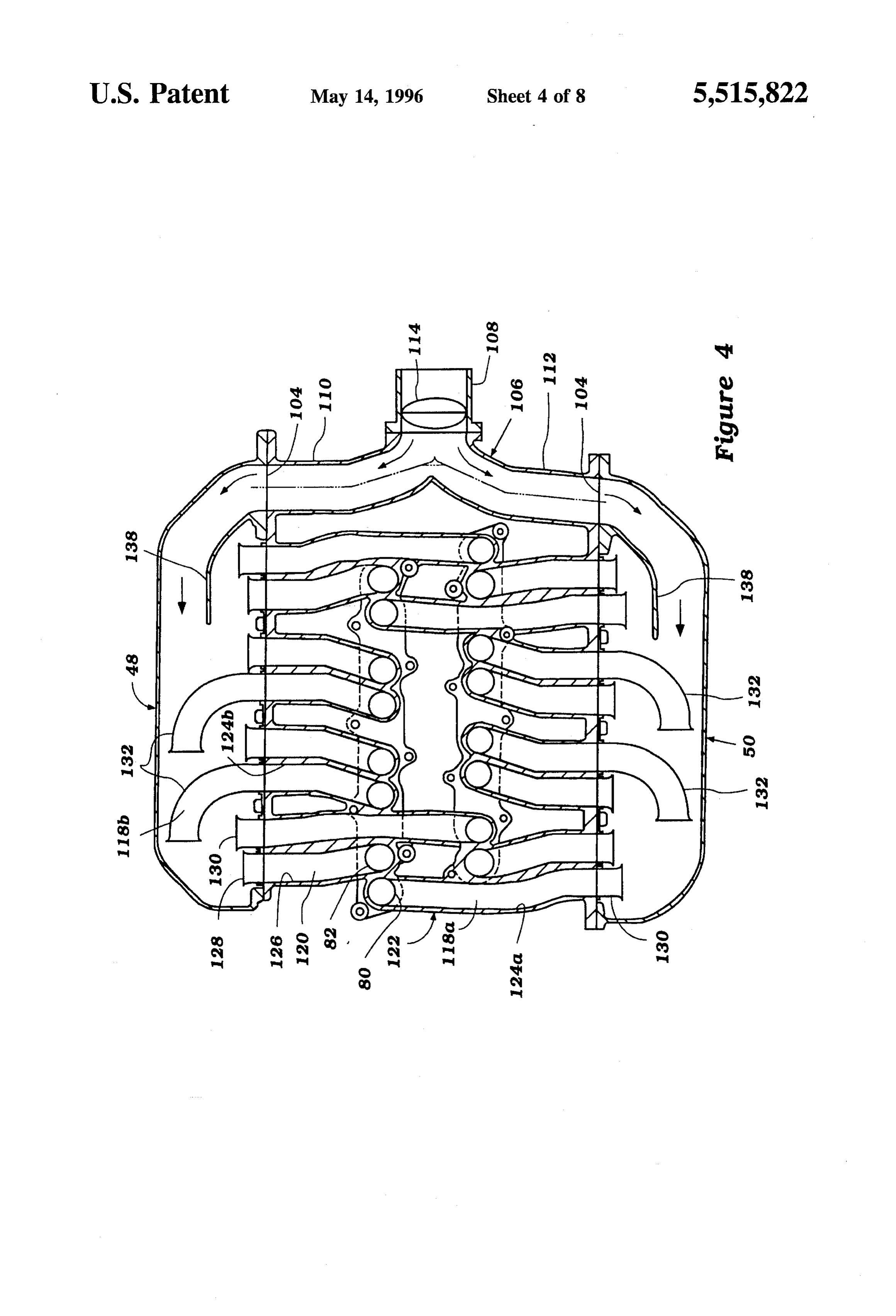
FIG. 3 is a top plan view of the internal combustion engine 20 to maintain a low profile underneath the hood 30. engine showing a preferred air intake induction system; Specifically, the plenum chambers 48, 50 are arranged so FIG. 4 is a cross-sectional view of the air intake induction that their lower surfaceslie generally juxtaposed and parallel system taken generally along the center lines of a plurality 30 to the upper surface of each respective cam cover 42, 44. of intake conduits; Furthermore, the vertical height of each plenum chamber 48, FIG. 5 is an elevational view of the internal combustion 50 is reduced, as compared with prior designs, due to the engine of FIG. 1 with portions shown in section, taken elimination of stacked sub-chambers within.
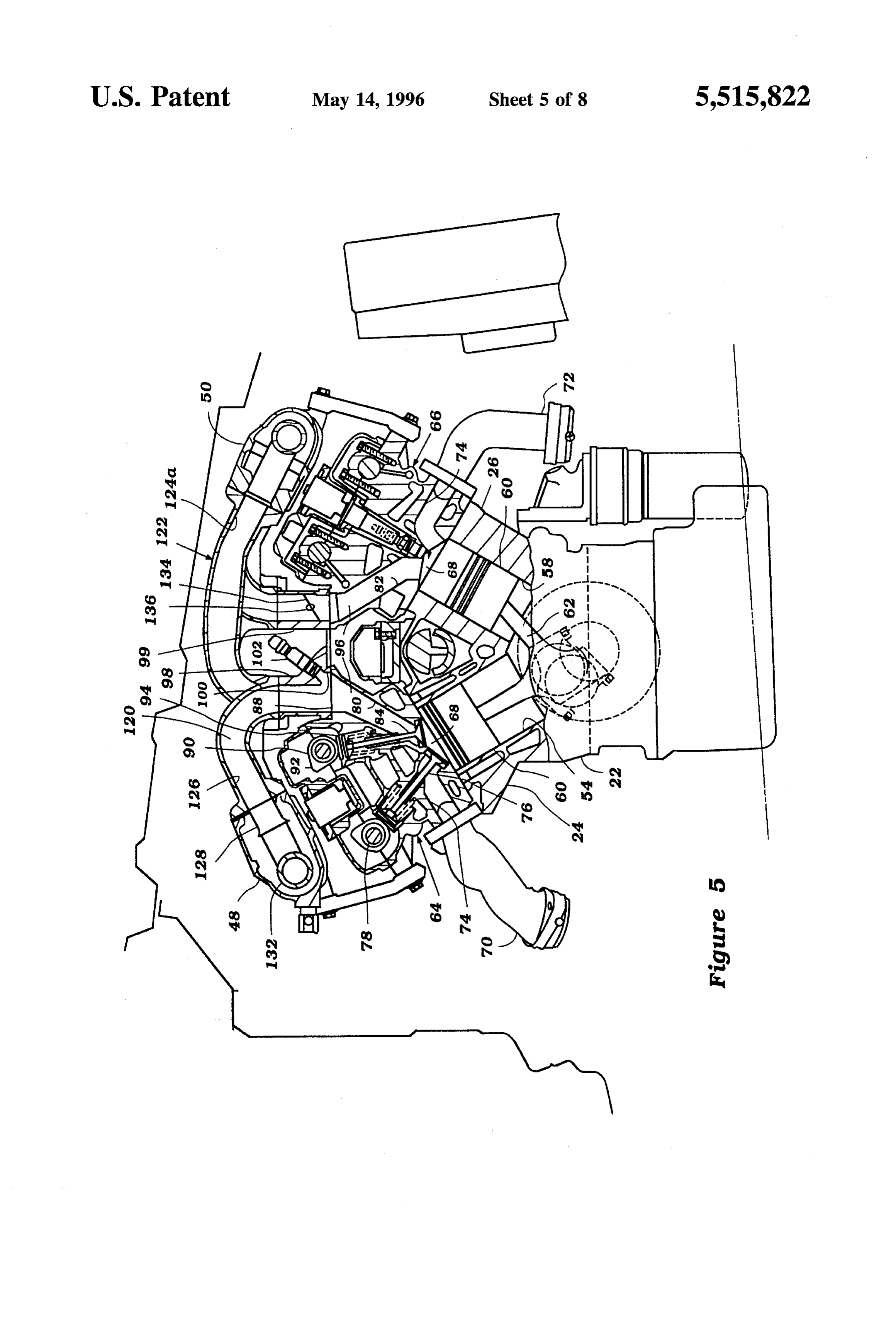
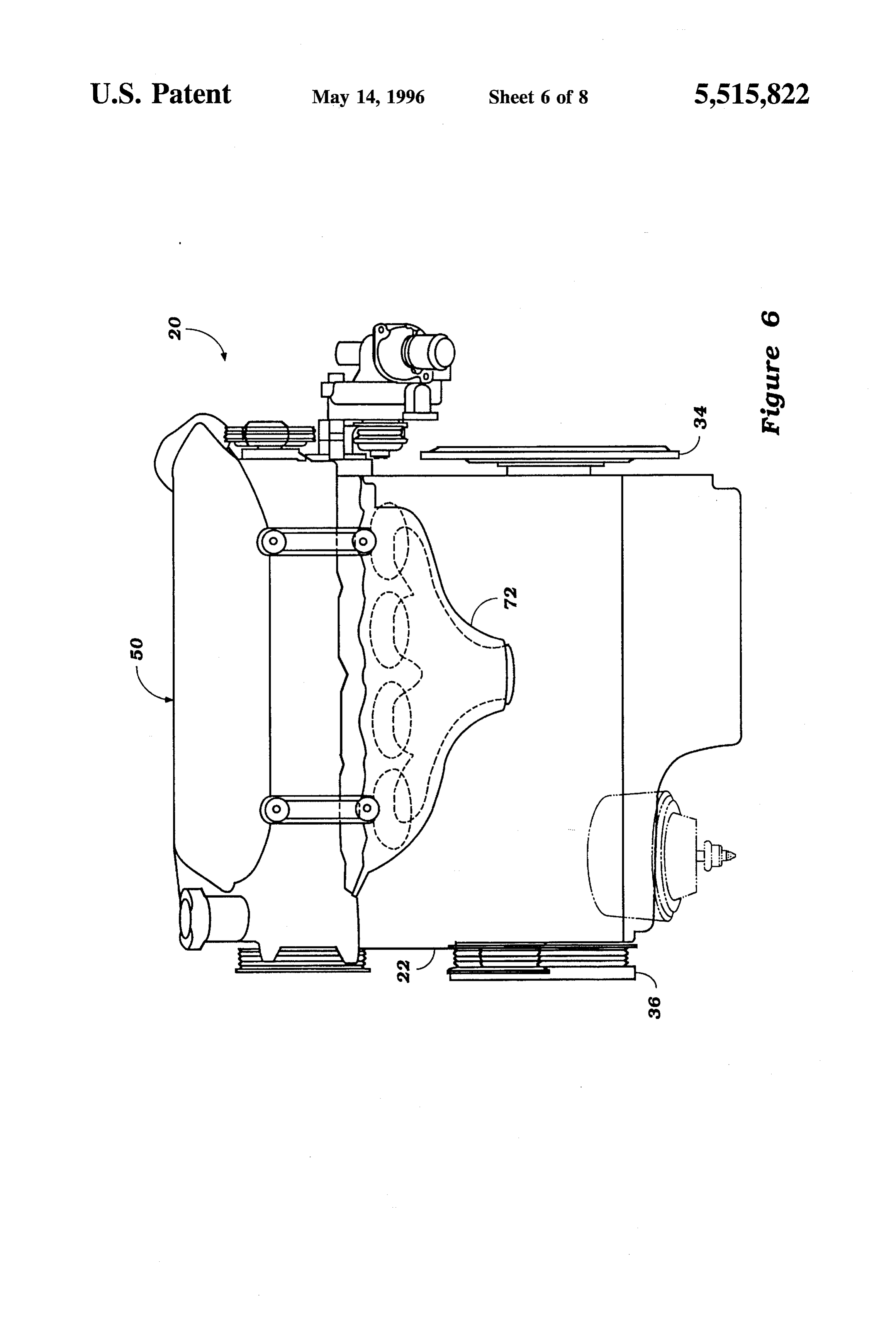
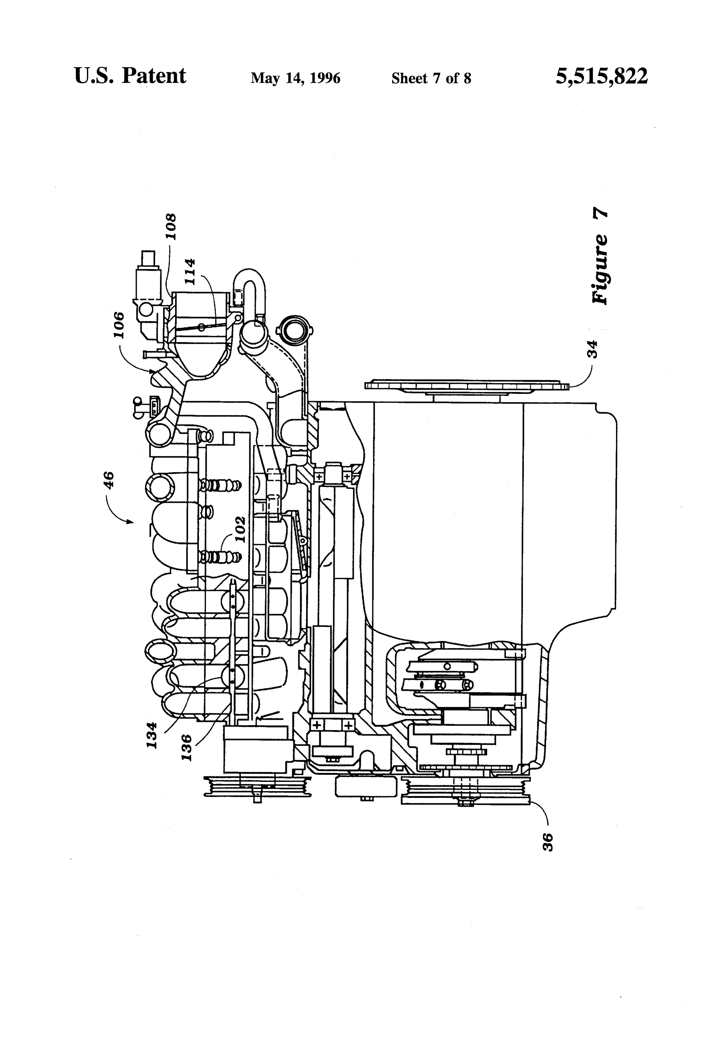
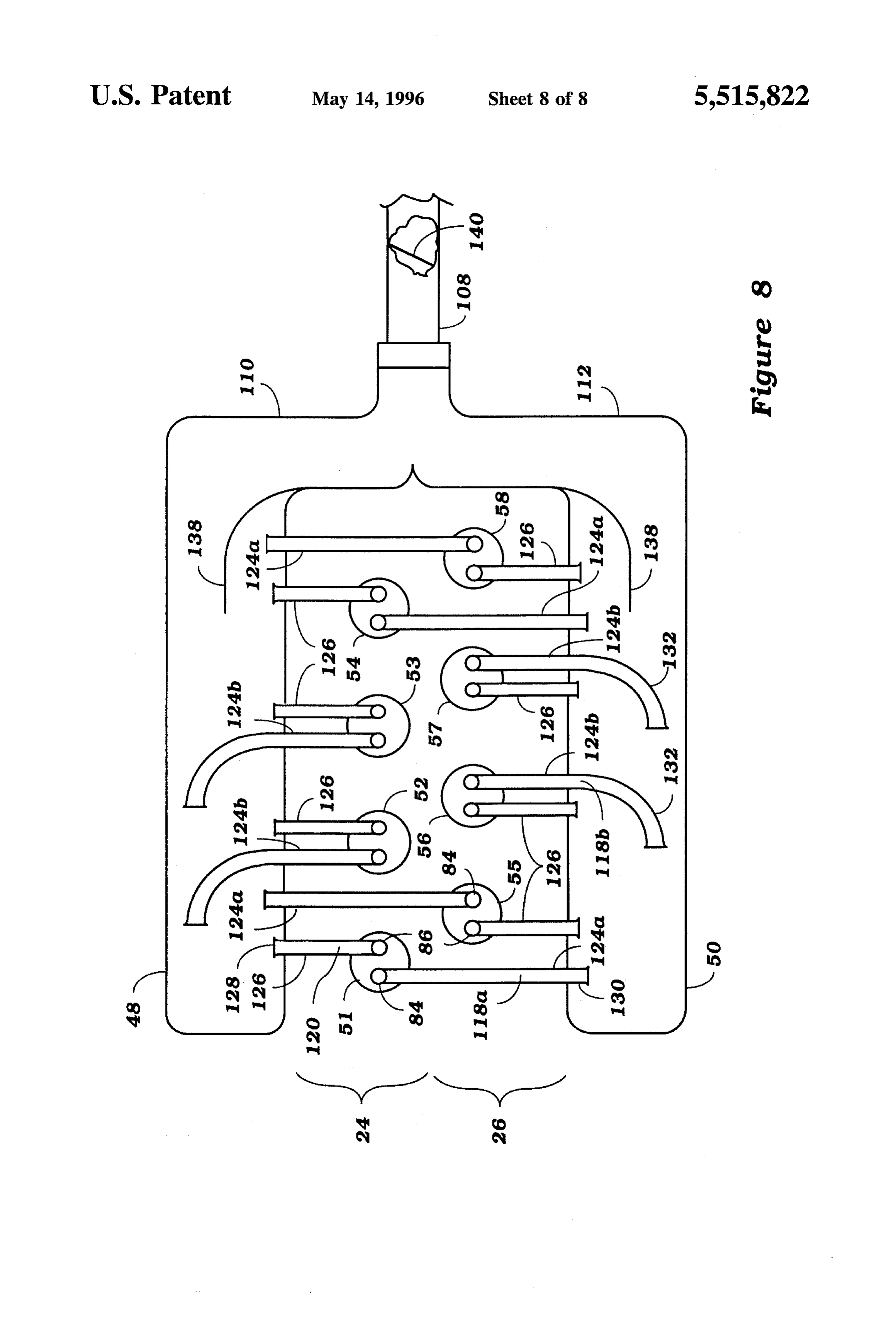
generally along line 5-5 of FIG. 3; Prior to a detailed description of the induction system 46, FIG. 6 is a side elevational view of the internal combus 35 an overview of the relevant internal components of the tion engine of FIG. 1; engine 20 is appropriate. With specific reference to FIGS. 5 FIG. 7 is a side elevational view of the internal combus and 8, the cylinder bank 24 is provided with four cylinder tion engine of FIG. 1 with portions shown in section, taken bores, as has been noted, which are shown as circles in FIG. generally along line 7-7 of FIG. 3; and 8 and are identified by the respective numerals 51-54. In a FIG. 8 is a schematic plan view of the air intake induction like manner, the cylinder bank 26 is also formed with four system of the present invention. cylinderbores, which are shown as circles and identified by the reference numerals 55-58 in FIG. 8. Pistons 60 are
DESCRIPTION OF THE PREFERRED reciprocally supported in each of the cylinder bores 51-58 EMBODIMENTS and are connected to a crankshaft in a known manner, as by means including connecting rods 62.
In the drawings the reference numeral 20 indicates gen A cylinder head, indicated generally by the reference erally an internal combustion engine constructed in accor numeral 64, is affixed in a known manner to the cylinder dance with an embodiment of the present invention. The bank 24. Similarly, a cylinder head 66 is affixed to the engine 20 is of the V-type and includes a cylinder block 22 cylinder bank 26. Each cylinder head 64 and 66 has a recess having angularly inclined banks 24 and 26. In the illustrated 50 cavity 68 formed therein for each of the cylinderbores. The embodiment, the engine 20 is of the V8-type, and each cavity 68, piston 60, and cylinder bores 51-58 form the cylinder bank 24, 26 defines four cylinder bores, as will be combustion chambers of the engine, and the reference described. The cylinder bores of the bank 24 are disposed at numeral 68 will be, at times, referred to as the combustion an angle to those of the bank 26, and in the illustrated chambers.
embodiment, this angle is 60 degrees. It is to be understood, 55 The combustion chambers 68 are generally hemispherical however, that the invention and certain facets of it are useful in shape, and each chamber is provided with a pair of with engines of other configurations and engines in which exhaust passages formed in the respective cylinder head 64 the angle between the banks is other than 60 degrees. The or 66, which extend from the chambers 68 and which are invention, however, has particular utility in conjunction with adapted to cooperate with respective exhaust manifolds 70 V-type engines, and particularly those in which a very 60 and 72. These exhaust passages are identified by the refer narrow or relatively shallow cylinder bank angle is ence numeral 74, as shown in FIG. 5. Exhaust valves 76 are employed. reciprocally supported in each of the cylinder heads 64, 66 FIG. 1 and FIG. 2, which are front and rear views of the and control the communication of the cylinder head exhaust engine 20, respectively, illustrate the 60-degree divergence passages 74 with the combustion chambers 68. The exhaust of the cylinder banks 24, 26. The engine 20 is shown 65 valves 76 associated with each cylinder bore 51-58 are mounted transversely within an engine compartment, gen operated in unison in a suitable manner, as by means of an erally shown at 28, and under a sloped engine hood 30. A overhead-mounted camshaft 78. While the number may
Page 12
vary, there are typically two exhaust valves 76 per cylinder, ally by the reference numeral 120, and including the cylinder with the communication ports into the cylinder being located head intake passage 82. The primary and secondary intake to the exterior side of the hemispherical combustion cham passages 118 and 120 are tuned, respectively, to provide ber 68. good induction efficiency for low speed and mid-range On the opposite sides of the hemispherical combustion running and high speed running, respectively, as described chamber 68 from the exhaust valves 76, each recess 68 of in the aforenoted commonly assigned patents. The short each cylinder head 64 and 66 is provided with a pair of secondary intake passages 120, as will be described, extend intake passages 80 and 82. As seen schematically in FIG. 8, from each of the cylinder 51 through 58 to the adjacent with the exhaust ports removed, the passages 80 terminate at plenum chamber 48 or 50.
an intake valve 84, while the passages 82 terminate at an 10 The longer primary intake passageways 18 are arranged intake valve 86. The portion of the passages 80, 82 that in a pair of series some of which extend from each cylinder extend through the respective cylinder heads 64 and 66 are 51 through 58 to the plenum chamber 48 or 50 disposed substantially identical in construction, and they each termi above the other cylinder bank, these primary intake pas nate in a generally horizontally extending surface 88 of the sageways of this series being identified by the suffix 'a.' cylinder heads. 15 Another series of primary intake passages extend from the The intake valves 84, 86 are, like the exhaust valves 76, cylinders 51 through 58 to the plenum chamber adjacent the operated by means of respective overhead-mounted cam cylinder bank and these primary intake passages are indi shafts 90, each supported for rotation in the respective cated by the suffix "b.” By alternating which plenum cham cylinder heads 64 or 66 in a known manner. The intake 20 ber serves the primary intake passage of the respective camshafts 90 have lobes 92 that cooperate with thimble cylinder it will be possible to choose a desired firing order, tappets 94 so as to operate the valves 84, 86 in a known have no two adjacent firing cylinders draw from the same manner. Coil compression springs are provided underneath plenum chamber under low and mid-range running condi the thimble tappets 94 for urging the valves 84, 86 toward tions, and maintain longer lengths for the primary intake their closed positions. The intake and exhaust camshafts 90 25 passages 118 than the secondary intake passages 120 while and 78 are driven from the crankshaft of the engine through still maintaining a relatively uncomplicated induction sys any suitable drive mechanism, preferably one of the type tem.
shown in the co-pending application of Manabu Kobayashi In addition to the cylinder head intake passages 80 and 82, and Yasuo Okamoto, entitled "Camshaft Operating System,' the primary and secondary intake passages 118 and 120 are attorney docket number YAMAH2.520A, and assigned to formed by passages formed in the throttle bodies 98 and the assignee hereof, the disclosure of which is incorporated 30 respective runners formed in an intake manifold, indicated herein by reference. generally by the reference numeral 122 which is affixed to As was described in prior U.S. Pat. No. 4,649,876 entitled the throttle bodies 98, 99 and the remainder of the engine in "Intake Means of Internal Combustion Engine,” assigned to a known manner. The primary intake head manifold runners the present assignee, the cylinder head intake passages 80, 35 are indicated by the reference numeral 124 while the sec 82 are separated from each other by a boundary wall that ondary runners are indicated by the reference numeral 126. extends from the valve seats and for a portion of the length The secondary manifold runners 126, as have been noted, of the passages. However, this wall terminates short of the are served by the plenum chamber 48 or 50 adjacent the cylinder head face 88 so as to provide an open area, respective cylinder bank 24 and 26 and relatively short generally indicated at 96, of limited length through which 40 trumpets 128 are formed in the plenum chambers 48 and 50 the passages 80 and 82 may communicate with each other. and communicate with these manifold secondary runners Just above the horizontal head surface 88, a pair of fuel 126 to complete the secondary intake passages 120. throttle bodies 98, 99 are mounted, in which a plurality of As can be seen in FIG. 8, the primary cylinder head intake recesses 100 are formed. A fuel injection nozzle 102 is passages 80 of the cylinders 51 and 54 of the cylinder bank mounted in a downward direction in each recess 100 for 45 24, and of the cylinders 55 and 58 of the cylinder bank 26, discharging fuel. Because of the central placement and are served by the plenum chambers 50 and 48, respectively, downstream pointing direction, the nozzles 102 provide a of the opposite cylinder banks 26 and 24, respectively. To good fuel distribution balance between the intake passages this end, the intake manifold 122 is provided with long 80 and 82. primary runners 124a that extend across the valley between Now with reference to FIGS. 3-5, the plenum chambers 50 the cylinder banks 24 and 26 and which enter the respective 48,50 have facing inlet openings 104 at their upstream ends, plenum chambers 48 or 50 through relatively short trumpets which receive atmospheric air from an intake device, indi 130 which trumpets are slightly longer than the secondary cated generally by the reference numeral 106, and which has trumpets 128. It should be noted that the cylinders served by a generally Y-shape in top plan. The intake device 106 has the plenum chamber of the opposite bank are the end a common throat portion 108 from which branches 110 and 55 cylinders of each cylinder bank 24 and 26 due to the firing 112 extend to the respective plenum chambers 48, 50. A order, as will hereinafter be noted. manually operated throttle valve 114 is supported in the Thus, the first series of primary intake passages 118a are throat 108 and is connected by a suitable linkage 116 to an comprised of the cylinder head intake passages 80, the short operator control for controlling the air flow into the induc passage through the throttle bodies 98, 99, the manifold tion system 46. A suitable air cleaner (not shown) is typically 60 runners 124, and the trumpet sections 130. The length of positioned upstream of the throat 108 for filtering the intake these intake passages is, as noted, substantially longer than air and for achieving such silencing as may be desired. that of the secondary intake passages 120 for the reasons As an important feature of the invention, each cylinder aforenoted.
51-58 is served by a primary, relatively long intake passage, The center cylinders 52 and 53 of the cylinder bank 24 indicated generally by the reference number 118 and which 65 and the center cylinders 56 and 57 of the cylinder bank 26 includes the cylinder head intake passage 80 and a second, are served by the adjacent plenum chambers 48 and 50, relatively short secondary intake passage, indicated gener respectively. To this end, the intake manifold 120 is provided
Page 13
with a second series of primary runners 124b which extend The total length of all the primary passages 118a, b, to the adjacent plenum chambers and therein cooperate with whether relatively straight or curvilinear, are approximately relatively long tubular sections 132 which are formed inte equal, resulting in a similar air flow therethrough. As a grally with, or as separate pieces connected to, the respective result, a relatively long air flow path is provided, which plenum chambers 48 and 50. These sections 132 are curved gives the opportunity to ensure laminar flow through the so as to provide an increase in their length and are termi induction system so that the passages consisting of the nated at inlet ends that face away from the inlet openings plenum chambers, the primary runners 124, the throttle body 104 at the opposite end of the respective plenum chamber 48 98, 99 passages, and cylinder head intake passages 80 may and 50. This permits the length of the second series of be tuned so as to give good torque characteristics at low and primary intake passages 118b to be equal to the length of the 10 mid-range running. At higher speeds, the throttle valves 134 first series of primary intake passages 118a so as to permit will open, and the secondary passages 120 can allow air equal tuning lengths. therethrough into the combustion chambers 68. The pas The flow through the secondary intake passages 120 to the sages consisting of the plenum chambers, the secondary respective cylinders 51 through 58 is controlled by butterfly runners 126, the throttle body 98, 99 passages, and the type throttle valves 134 journalled on throttle valve shafts 15 cylinder head intake passages 82 are kept very short to 136 within the throttle bodies 98, 99. Preferably these permit tuning for maximum power output at high speeds. throttle valves 134 are disposed above the recesses 100 into To reduce the adverse effects of successively drawing air which the fuel injectors 102 discharge. The common mount from one of the two plenum chambers 48, 50, the firing order ing of the throttle valves 134 in this manner ensures the of the cylinders is such that none of the primary passages valves associated with each plenum chamber 48 and 50 will 20 118a,b draw air successively from a single plenum chamber. be operated in unison. The beneficial spatial arrangement of the runners 124, 126 At one end of the engine 20, the throttle valve shaft 136 is such that it is impossible to avoid pulling air from associated with each plenum chamber is extended and successive firing of cylinders from one of the two plenum connected by means of a linkage system to a vacuum motor. chambers at higher speeds when the throttle valves 134 are The vacuum motor senses induction system vacuum down 25 opened. However, to reduce any adverse performance stream of the throttle valves 134. The construction and effects, at high speeds the firing order is such that there is a operation of the vacuum motor is such that the throttle minimum of two instances where cylinders firing succes valves 134 will be held in their closed position until induc sively within each eight-cylinder cycle draw air from the tion system pressure increases (manifold vacuum same plenum chamber. One preferred firing order is given by decreases), so as to indicate that the engine has approached 30 the sequence of cylinder firings 51-55-54-52-56-53-57-58. its maximum power output, or power demand condition. At In this sequence, as can be verified from the schematic this point, the valves 134 will be opened and air allowed to drawing of FIG. 8, none of the cylinders firing successively flow through the secondary intake passages 120. The short draws air through the primary passages 118a,b from the length of the secondary intake passages 120 offers a very same plenum chamber. However, cylinders 54 and 52 fire low resistance to airflow suitable for the high power demand 35 successively and, at high speeds, will draw air successively condition of the engine running at high speeds. from plenum chamber 48 through their respective secondary One important aspect of the present invention is the passages 120. Likewise, cylinders 57 and 58 fire succes reduction in the external conduit plumbing above the engine sively and will draw air from the plenum chamber 50 20. Intake air is provided to the cylinders from the plenum through their respective secondary passages 120. This situ chambers 48 or 50 in a manner which enhances performance 40 ation, in which two out of the eight successive cylinder of the cylinders by substantially avoiding intake pulses firings draw air from the same plenum chamber through the drawn from the same plenum chamber successively. secondary conduits at high speeds, is a relatively minor loss Specific reference is now made to FIGS. 4 and 8, wherein in engine power output and is substantially mitigated by the the longitudinal shape of each of the intake passages 118, benefits realized by the savings in engine volume from the 120 is shown in cross section. It should be noted that the 45 reduced external plumbing.
cross-section of FIG. 4 is taken along an approximate The present induction system 46 further incorporates an centerline of each of the runners 124, 126, or along two improved airflow arrangement in which the difference in air planes extending through each plenum chamber 48, 50, and flow lengths between the common inlet throat 108 and each forming an angle of approximately 120° with each other. of the intake passages 118, 120 is reduced. More particu Cylinders 51, 54, 55, and 58 each have a relatively straight 50 larly, as seen in FIG. 4, each plenum chamber 48, 50 primary passages 118a extending from the cylinder head incorporates a baffle 138 extending generally from the inlet intake passage 80 to the opposite plenum chamber, as well openings 104 into the central portion of the chambers. The as a relatively straight and short secondary passage 120 baffles 138 generally lie parallel to the external surface shape extending from the cylinder head intake passage 82 to the of the plenum chambers 48, 50, and thus initially extend adjacent plenum chamber. Cylinders 52,53,56, and 57, on 55 transverse and gradually curve to terminate in a longitudinal the other hand, have curvilinear primary passages 118b direction. The airflow thus enters through the throat 108 and connected between the cylinder intake passage 80 and the branches 110, 112 into the respective plenum chambers 48, adjacent plenum chamber and relatively straight secondary 50 to be channeled into the approximate center of the passages 120 connecting intake passages 82 with the adja plenum chambers for subsequent exhaust through one of the cent plenum chamber. The curvilinear shape of the middle 60 trumpets 128, 130, 132 leading to the intake passages 118, cylinder primary passages 118b allows the conduits to 120.This arrangement thus reduces the differences between terminate within the adjacent plenum chamber without add the air flow lengths serving the passages 118, 120, and thus ing substantial external plumbing to the induction system reduces cylinder-to-cylinder variation. 46. Approximately half of the length of each of the curvi In addition to having a common throttle valve 114 that linear primary passages 118b lies within the plenum cham 65 controls the flow of intake air to the plenum chambers 48, bers with the conduits opening up toward the end of the 50, the induction system 46 is also provided with a single chamber opposite the inlet opening 104. flow sensor 140 (FIG. 8), which may be of the vane type and
Page 14
which senses the air flow into the induction system. This ing plenum chamber for each cylinder. Additionally, as has sensor 140 is connected through a suitable control system been noted, the plenum chambers are mounted substantially for controlling the amount of fuel flow delivered to the fuel parallel to the upper surfaces of the cam covers, so that the injection nozzles 102. The specific construction for control profile of the engine is still further reduced, as seen in FIGS. ling the fuel flow may be of any known type but preferably 5 1 and 2. The present internal combustion engine thus enjoys includes the serpentine fuel rail 130, shown in FIG. 3, and the benefits of the improved induction system described and aforementioned fuel pump pulley 40 and associated fuel can be constructed in a substantially smaller volume to allow pump. hoodlines to be lowered, providing further flexibility to the The operation of the induction system 46 will now be auto body designer.
described. During low speed running, the manually operated 10 Although an embodiment of the invention has been illus common throttle valve 114 will be actuated under the trated and described, various changes and modifications may operator's control and will be opened only to a small degree. be made, without departing from the spirit and scope of the There will be a relatively high induction system vacuum invention, as defined by the appended claims. exerted on the vacuum motors, so as to hold the throttle valves 134 in their closed positions. Hence, substantially all 5 We claim:
1. An induction system for an internal combustion engine the induction air for the engine will be supplied through the having a pair of angularly disposed cylinder banks each inlet device 106 to the plenum chambers 48 and 50, and having at least two cylinders for a total of N cylinders, first specifically to their outlets leading to the constantly open and second plenum chambers each juxtaposed to a respec primary passages 118a,b. The air is transferred from the tive one of said cylinder banks, a first series of first intake plenum chambers 48, 50 through the relatively long intake 20 passages, each of said first intake passages extending from passages 118 to the combustion chambers 68. Hence, as has each of said cylinders to the juxtaposed plenum chamber, a already been noted, a relatively long airpath is provided that will ensure laminar flow. However, the air will flow through second series of second intake passages of a number less a relatively small cross-sectional area of the total induction than the number of cylinders, each of said second intake system area serving each cylinder bore 51-58 so that the passages extending from a first number n of said cylinders induction will be at a high velocity. This will ensure a rapid 25 to the juxtaposed plenum chamber, and a third series of third intake passages, each of said third intake passages extending rate of flame propagation in the chambers, which ensures from the remainder (N-n) of said cylinders to the nonjux that there will be good combustion. taposed plenum chamber.
As the load on the engine increases and the manually operated throttle valve 114 is progressively opened, there 30 the2.second
The induction system as set forth in claim 1, wherein and third intake passages each have the same will be a point when the intake passages 118a, b cannot length.
supply the full charge requirements of the combustion 3. The induction system as set forth in claim 2, wherein chamber 68. This occurs at a point before that at which the the length of the first intake passages is different from the throttle valves 134 are opened. At this point, induction charge may flow through the communicating area 96 to enter 35 lengths4. The of the second and third intake passages.
induction system as set forth in claim 3, wherein the chamber 68 through both the cylinder head intake the first intake passages are shorter than the second and third passages 80 and 82 and past both intake valves 84 and 86. intake passages.
As has been previously noted, this communication provides 5. The induction system as set forth in claim 4, wherein significantly improved mid-range performance, since it eliminates or substantially reduces the dip that would oth 40 into second the intake passages extend for a substantial length the juxtaposed plenum chamber.
erwise occur in the torque curve of the engine at this point. 6. The induction system as set forth in claim 2, wherein As the load continues to increase and the throttle valve the second intake passages extend for a substantial length 114 is progressively opened, the induction system vacuum into the juxtaposed plenum chamber. will eventually reach a point where the vacuum motor no 7. The induction system as set forth in claim 6, further longer holds the control valves 134 in their closed position, 45 including an atmospheric air inlet at one end of each of said and these valves will open. Thus, the effective area of the plenum chambers.
induction system serving each cylinder bore 51-58 will 8. The induction system as set forth in claim 7, wherein Substantially increase, and a very good maximum output can the ends of the second intake passages face away from the be achieved. Furthermore, as has been noted, the intake atmospheric air inlets of the juxtaposed plenum chambers. passages 120 are relatively short and will offer low flow 50 9. The induction system as set forth in claim 8, wherein resistance and may be tuned so as to achieve the desired flow the atmospheric air inlets of the plenum chambers are at the under this running condition. same end of the engine and are served by a common It should be readily apparent that the described construc atmospheric air intake device in which a single throttle valve tion permits good induction efficiency and cylinder charging is positioned.
under all running conditions. In addition, the use of the two 55 10. The induction system as set forth in claim 7, wherein plenum chambers 48 and 50 provide a large volume, which conduit means extend from the atmospheric air inlets of the ensures good distribution and reduces induction system plenum chambers to a point disposed substantially centrally noise. By employing the two spaced-apart boxes, it is of the length of the respective plenum chamber. possible to obtain a relatively low hoodline, as indicated in 11. The induction system as set forth in claim 10, wherein FIGS. 1 and 2. Furthermore, the configuration permits the 60 the ends of the second intake passages face away from the use of separately tuned induction passages for each cylinder atmospheric air inlets of the juxtaposed plenum chambers. in a compact area. The volume of the associated external 12. The induction system as set forth in claim 11, wherein plumbing of the induction system is further reduced by the the atmospheric air inlets of the plenum chambers are at the provision of the curvilinear runners 124b extending within same end of the engine and are served by a common the plenum chambers 48, 50. This arrangement provides an 65 atmospheric air intake device in which a single throttle valve equally long air flow path to each cylinder 51-58 without is positioned.
requiring that the primary passages 118 extend to the oppos 13. The induction system as set forth in claim 1, wherein
Page 15
the cylinders of the engine fire in an order such that each 28. The induction system as set forth in claim 27, wherein plenum chamber does not serve a successively firing cylin the second intake passages extend for a substantial length der through the second and third series of intake passages. into the juxtaposed plenum chamber. 14. The induction system as set forth in claim 13, wherein 29. The induction system as set forth in claim 28, further the second and third intake passages each have the same including an atmospheric air inlet at one end of each of said length. plenum chambers.
15. The induction system as set forth in claim 14, wherein 30. The induction system as set forth in claim29, wherein the length of the first intake passages is different from the the ends of the second intake passages face away from the lengths of the second and third intake passages. atmospheric air inlets of the juxtaposed plenum chambers. 16. The induction system as set forth in claim 15, wherein 10 the31. The induction system as set forth in claim30, wherein atmospheric air inlets of the plenum chambers are at the the first intake passages are shorter than the second and third same end of the engine and are served by a common intake passages. atmospheric air intake device in which a single throttle valve 17. The induction system as set forth in claim.16, wherein is positioned.
the second intake passages extend for a substantial length 32. The induction system as set forth in claim31, wherein into the juxtaposed plenum chambers. 5 conduit means extend from the atmospheric air inlets of the 18. The induction system as set forth in claim 17, further plenum chambers to a point disposed substantially centrally including an atmospheric air inlet at one end of each of said of the length of the respective plenum chamber. plenum chambers. 33. The induction system as set forth in claim 1, wherein 19. The induction system as set forth in claim 18, wherein each cylinder bank has at least four cylinders (N28). the ends of the second series of intake passages face away 20 34. The induction system as set forth in claim 33, wherein from the atmospheric air inlets of the adjacent plenum the cylinder banks are disposed at a V angle to each other. chamber. 35. The induction system as set forth in claim34, wherein 20. The induction system as set forth in claim 19, wherein each cylinder has two intake valves, one of said intake the atmospheric air inlets of the plenum chambers are at the valves being served by a one of the first intake passages and same end of the engine and are served by a common 25 the other of the intake valves being served by one of either atmospheric air intake device in which a single throttle valve the second or the third intake passages. is positioned. 36. The induction system as set forth in claim35, wherein 21. The induction system as set forth in claim 20, wherein the second and third intake passages each have the same conduit means extend from the atmospheric air inlets of the length.
plenum chambers to a point disposed substantially centrally 30 37. The induction system as set forth in claim36, wherein of the length of the respective plenum chamber. the length of the first intake passages is different from the 22. The induction system as set forth in claim 21, wherein lengths of the second and third intake passages. the cylinder banks are disposed at a V angle and each 38. The induction system as set forth in claim 37, wherein cylinder bank is covered by a cam cover having an upper the first intake passages are shorter than the second and third surface that extends generally at an acute angle to a hori 35 intake passages.
Zontal plane perpendicular to a vertical plan passing through 39. The induction system as set forth in claim35, wherein the center of the V and wherein the plenum chambers have the cylinders of the engine fire in an order such that each lower surfaces that extend substantially parallel to the upper plenum chamber does not serve a successively firing cylin surface of the adjacent cam cover for maintaining a low der through the second and third series of intake passages. overall height for said engine. 40 40. The induction system as set forth in claim39, wherein 23. The induction system as set forth in claim 13, wherein the second and third intake passages each have the same the cylinder banks are disposed at a V angle and each length.
cylinder bank is covered by a cam cover having an upper 41. The induction system as set forth in claim 40, wherein Surface that extends generally at an acute angle to a hori the length of the first intake passages is different from the Zontal plane perpendicular to a vertical plan passing through 45 lengths of the second and third intake passages. the center of the V and wherein the plenum chambers have 42. The induction system as set forth in claim 41, wherein lower surfaces that extend substantially parallel to the upper the first intake passages are shorter than the second and third surface of the adjacent cam cover for maintaining a low intake passages.
overall height for said engine. 43. The induction system as set forthin claim 42, wherein 24. The induction system as set forth in claim 1, wherein 50 the second intake passages extend for a substantial length the cylinder banks are disposed at a V angle and each into the juxtaposed plenum chamber. cylinder bank is covered by a cam cover having an upper 44. An induction system for an internal combustion surface that extends generally at an acute angle to a hori engine having a plurality of cylinders aligned in a bank, a Zontal plane perpendicular to a vertical plan passing through plenum chamber having an atmospheric air inlet at one end the center of the V and wherein the plenum chambers have 55 thereof, a plurality of inlet passages extending from said lower surfaces that extend substantially parallel to the upper cylinders into said plenum chamber and opening therein at surface of the adjacent cam cover for maintaining a low positions spaced along its length, and means forming an overall height for said engine. internal duct in said plenum chamber extending from said 25. The induction system as set forth in claim 24, wherein atmospheric air inlet to a point in said plenum chamber the second and third intake passages each have the same 60 Substantially at the center of the openings on said inlet length. passages in said plenum chamber.
26. The induction system as set forth in claim 25, wherein 45. The induction system as set forth in claim 44, wherein the length of the first intake passages is different from the the inlet passages each terminate at aside wall of the plenum lengths of the second and third intake passages. chamber.
27. The induction system as set forth in claim 26, wherein 65 46. The induction system as set forth in claim 45, further the first intake passages are shorter than the second and third including a further series of inlet passage opening into said intake passages. plenum chamber.
Page 16
47. The induction system as set forth in claim 46, wherein device has a single throttle valve for controlling the air flow certain of the further series of inlet passages extend from the to each of said plenum chambers.
same cylinders as the first mentioned plurality of inlet 55. The induction system for a V-type engine as set forth passages. in claim 51, wherein each cylinder of the engine has a first 48. The induction system as set forth in claim 7, wherein intake passage extending from the cylinder to the adjacent the certain of said further series of inlet passages extend for plenum chamber and a second intake passage, said second a substantial length into the plenum chamber. intake passages of certain of said cylinders extending to the 49. The induction system as set forth in claim 48, wherein adjacent plenum chamber and the remaining of said second the certain of the further series of inlet passages face away inlet passages extending to the plenum chamber adjacent the from the end of the internal duct. 10 other cylinder bank.
50. The induction system as set forth in claim 49, wherein 56. The induction system for a V-type engine as set forth the remaining of the further series of inlet passages serve in claim 55, wherein the second series of intake passages all cylinders of another bank of cylinders of the engine and have the same length.
57. The induction system for a V-type engine as set forth terminate in the side wall of the plenum chamber.
51. An induction system for a V-type engine having a pair 15 is greater56,than in claim wherein the length of the second intake passages the length of the first intake passages.
of cylinder banks disposed at a V angle to each other, said 58. The induction system for a V-type engine as set forth cylinder banks each having a cam cover associated therewith in claim 57, further including an atmospheric air inlet at one with the upper surfaces of said cam covers lying at acute end of each of said plenum chambers. angles to a horizontal plane perpendicular to a vertical plane 59. The induction system for a V-type engine as set forth bisecting the V angle between said cylinder banks, a pair of 20 in claim 58, wherein the plenum chamber atmospheric air plenum chambers each extending along the upper surface of inlets are at the same end of the engine and are served by a a respective one of said cam covers and having a lower common atmospheric air induction device. surface extending substantially parallel to and along sub 60. The induction system for a V-type engine as set forth stantially the entire width of the upper surface of said cam in claim 59, wherein the common atmospheric air induction covers for maintaining a low profile for said engine, and 25 device has a single throttle valve for controlling the air flow intake passages extending from said cylinders into said to each of said plenum chambers.
plenum chambers for charging said cylinders. 61. An induction system for a V-type engine as set forth 52. The induction system for a V-type engine as set forth in claim 51, wherein the upper surfaces of the plenum in claim 51, further including an atmospheric air inlet at one chambers also extend substantially parallel to the upper end of each of said plenum chambers. 30 surface of the cam covers.
53. The induction system for a V-type engine as set forth 62. An induction system for a V-type engine as set forth in claim 52, wherein the plenum chamber atmospheric air in claim 51, further including means formed at the outer inlets are at the same end of the engine and are served by a sides of the cylinder banks for providing support for the common atmospheric air induction device. outer ends of the respective plenum chambers. 54. The induction system for a V-type engine as set forth 35 in claim 53, wherein the common atmospheric air induction ck : k k :
Provenance
- Collection
- Cited prior art
- Original PDF
- patentimages.storage.googleapis.com →
- Filed
- 1994-05-19
- Pages
- 16
- Method
- pdftotext (the PDF's own text layer) + pdftoppm 300dpi page scans
- Source
- Google Patents bibliographic record
- Granted
- 1996-05-14
- Inventors
- Manabu Kobayashi; Akira Yamaguchi; Yamaha Motor Co Ltd
- Transcribed from
- patentimages.storage.googleapis.com →