patent · US4892593
Solar trap
9 January 1990
Page 1 — bibliographic record
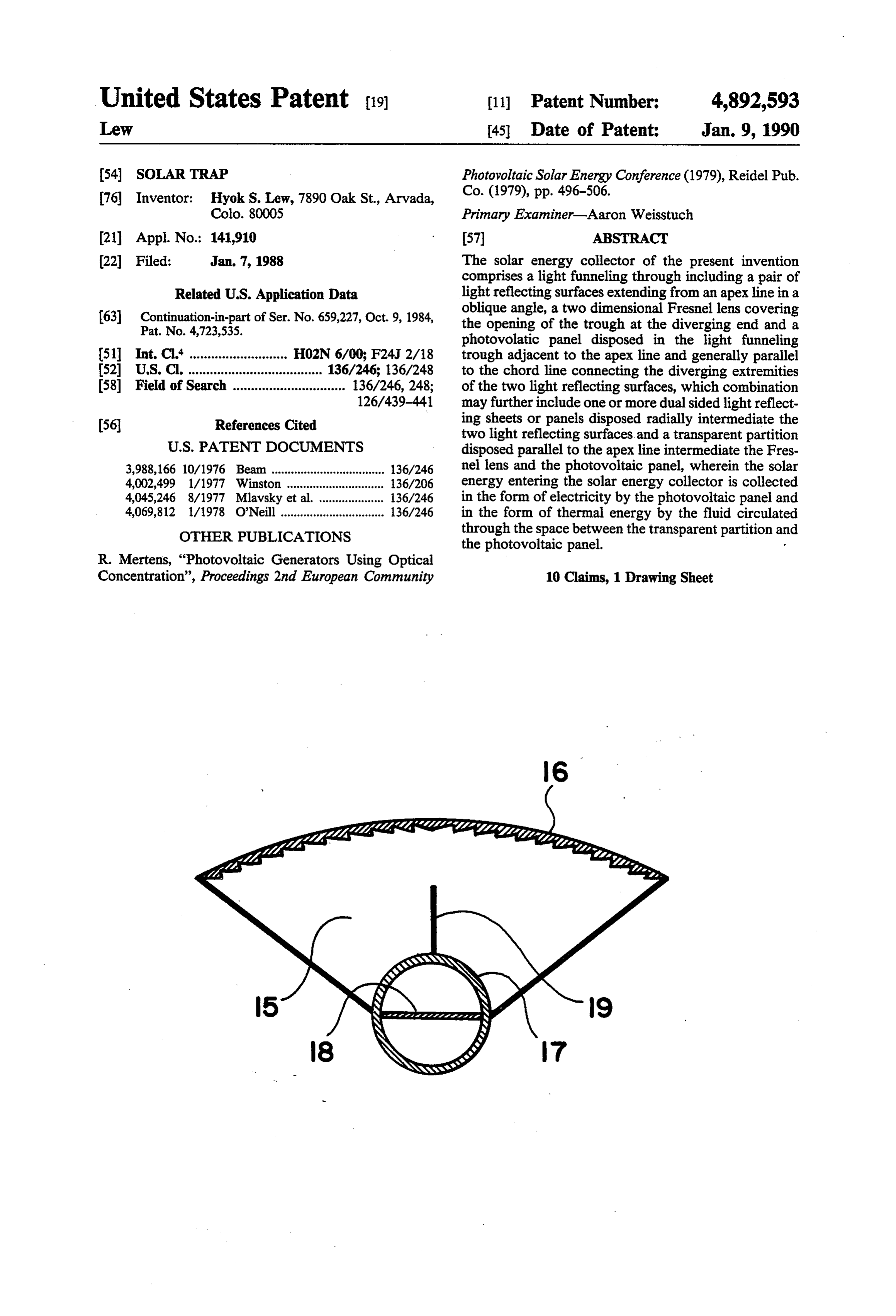
United States Patent (19) 11 Patent Number: 4,892,593 Lew 45 Date of Patent: Jan. 9, 1990 (54) SOLAR TRAP Photovoltaic Solar Energy Conference (1979), Reidel Pub. 76) Inventor: Hyok S. Lew, 7890 Oak St., Arvada, Co. (1979), pp. 496-506.
Colo. 80005 Primary Examiner-Aaron Weisstuch (21) Appl. No.: 141,910 (57) ABSTRACT (22 Filed: Jan. 7, 1988 The solar energy collector of the present invention comprises a light funneling through including a pair of
Related U.S. Application Data light reflecting surfaces extending from an apex line in a 63 Continuation-in-part of Ser. No. 659,227, Oct. 9, 1984, oblique angle, a two dimensional Fresnel lens covering Pat. No. 4,723,535. the opening of the trough at the diverging end and a photovolatic panel disposed in the light funneling 51 int. C. ............. ... H02N 6/00; F24J 2/18 trough adjacent to the apex line and generally parallel 52 U.S. Cl. ..................................... 136/246; 136/248 to the chord line connecting the diverging extremities 58 Field of Search ............................... 136/246, 248; of the two light reflecting surfaces, which combination 126/439-441 may further include one or more dual sided light reflect (56) References Cited ing sheets or panels disposed radially intermediate the two light reflecting surfaces and a transparent partition
3,988,166 10/1976 Beam ................................... 136/246 nel lens and the photovoltaic panel, wherein the solar 4,002,499 1/1977 Winston .............................. 36/206 energy entering the solar energy collector is collected 4,045,246 8/1977 Mlavsky et al. .................... 136/246 in the form of electricity by the photovoltaic panel and 4,069,812 1/1978 O'Neill ................................ 136/246 in the form of thermal energy by the fluid circulated OTHER PUBLICATIONS through the space between the transparent partition an the photovoltaic panel.
R. Mertens, “Photovoltaic Generators. Using Optical
Concentration', Proceedings 2nd European Community 10 Claims, 1 Drawing Sheet
Page 2
Drawing sheet — no readable text.
Page 3
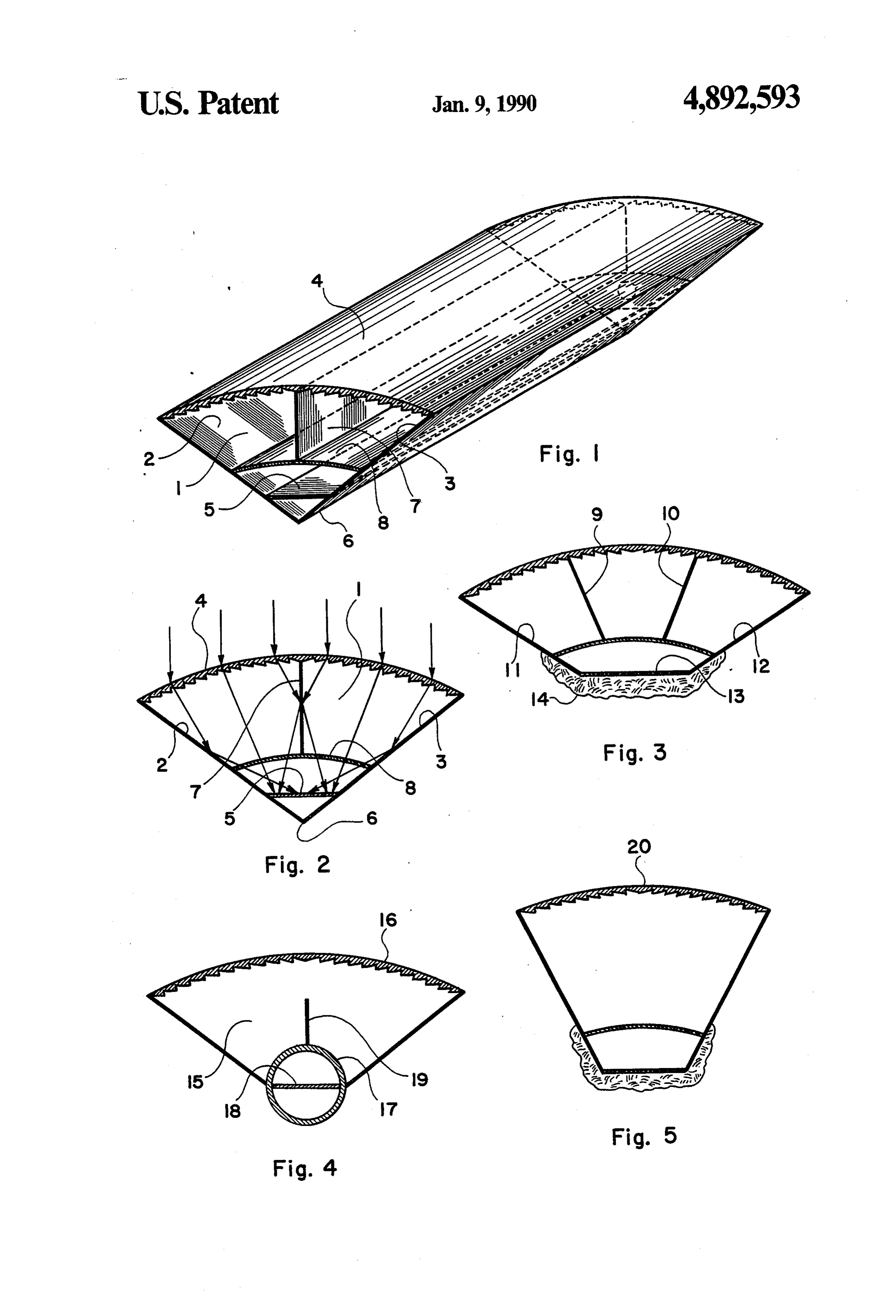
FIG. 1 illustrates a perspective view of an embodi
SOLAR TRAP ment of the solar energy collector constructed in accor dance with the principles of the present invention.
BACKGROUND OF THE INVENTION FIG. 2 illustrates a cross section of the embodiment This patent application is a continuation-in-part appli 5 shown in FIG. 1.
FIG. 3 illustrates a cross section of another embodi cation of patent application Ser. No. 06/659,227 entitled ment of the solar energy collector of the present inven “Solar Trap" filed on Oct. 9, 1984, now U.S. Pat. No. tion.
4,723,535 issued Feb. 19, 1988. FIG. 4 illustrates a cross section of a further embodi As described in the aforementioned parent applica 10 ment tion, the light funneling trough covered with a two tion. of the solar energy collector of the present inven dimensional Fresnel lens provides one of the most eco FIG. 5 illustrates a cross section of yet another em nomic and practical methods for concentrating solar bodiment of the solar energy collector of the present energy in the art of solar energy collectors. In most invention.
solar thermal energy applications, the required temper 15 ature is beyond the temperature of the solar thermal DESCRIPTION OF THE ILLUSTRATED energy collected by flat collectors and consequently, a EMBODIMENTS concentrating solar energy collector is required. The In FIG. 1 there is illustrated a perspective view of an parent application of this patent application has pro embodiment of the solar trap constructed in accordance vided a highly economic and practical concentrating 20 with the principles of the present invention, that com solar energy collector employing a light funneling prises a light funneling trough i including a pair of light trough covered with a two dimensional Fresnel lens, reflecting surfaces 2 and 3 arranged into a trough and a which satisfies the requirement of high temperature in two dimensional Fresnel lens 4 covering the opening of solar thermal energy collection. The cost of photovol the trough at the diverging end, and a photovoltaic taic panels is very high, which high cost is the obstacle 25 panel 5 facing the opening of the light funneling trough to the widespread use of solar voltaic energy collectors. 1, which is disposed within the light funneling trough 1 One way to reducing the cost of solar voltaic energy in a parallel relationship with respect to the apex line 6 collectors is to employ a sunlight concentrating device of the light funneling trough 1. The solar energy collec that drastically reduces the required surface area of the tor further includes a dual-sided light reflecting sheet or photovoltaic cells. 30 panel 7 disposed radially intermediate the two light reflecting surfaces 2 and 3, and a transparent partition 8
BRIEF SUMMARY OF THE INVENTION disposed intermediate the two dimensional Fresnel lens The primary object of the present invention is to 4 and the photovoltaic panel 5, which partition divides provide a solar energy collector that directs the sunlight 35 the interior space of the solar collector into two com in a concentrated state onto the photovoltaic panel. partments in a generally leak-proof arrangement. Another object is to provide a concentrating solar In FIG. 2 there is illustrated a cross section of the energy collector collecting the solar energy in the form alongtrap solar shown in FIG. 1, which cross section is taken a plane perpendicular to the apex line 6 of the of electricity as well a in the form of heat.
A further object is to provide a solar energy collector light funneling trough 1. The sunlight entering the light comprising a light funneling trough covered with a two funneling trough 1 is refracted by the two dimensional Fresnel lens 4 into directions approximately converging dimensional Fresnel lens and a photovoltaic panel fac towards ing the Fresnel lens disposed adjacent and parallel to the apex the photovaltaic panel 5 disposed adjacent to line 6 of the light funneling trough 1, which the apex of the light funneling trough. sunlight so refracted is funneled towards the photovol Yet another object is to provide a solar energy collec taic panel 5 by the two light reflecting surfaces 2 and 3 tor comprising the photovoltaic panel disposed in the 45 as well as by the dual-sided light reflecting sheet 7 until light funneling trough with a two dimensional Fresnel lens cover, which further includes one or more dual all of the sunlight entering the solar energy collector sided light reflecting partitions radially disposed inter irradiatesirradiating the photovoltaic panel 5. The concentrated mediate the two light reflecting surfaces constituting 50 sunlight electrical energy photovoltaic panel 5 is converted to by the photovoltaic panel 5 and to the light funneling trough. thermal energy that heats the heat transfer fluid circu Yet a further object is to provide a solar energy col lated through the space intermediate lector comprising the photovoltaic panel disposed in the partition 8 and the photovoltaic panelthe transparent light funneling trough with a two dimensional Fresnel transfer fluid is heated by the greenhouse effect heat 5, which lens cover, which further includes a transparent parti 55 vided by the transparent partition 8 as well as bypro the tion disposed intermediate the Fresnel lens and the pho photovoltaic panel 5 heated by the sunlight. The solar tovoltaic panel, wherein fluid circulated through the energy collector of the present invention shown in space intermediate the transparent partition and photo FIGS. 1 and 2 provides the following advantages over voltaic panel collects thermal energy from sunlight, other existing arts of solar energy collecting technol while the photovoltaic panel collects electrical energy 60 ogy: Firstly, the light funneling trough of the present from sunlight. invention does not require any high degree of accuracy These and other objects of the present invention will and precision in the geometry and construction thereof. become cler as the description thereof progresses. As a consequence, it provides a highly economic and BRIEF DESCRIPTION OF THE FIGURES lightweight solar concentrator collecting the solar en 65 ergy at the concentrated level. Secondly, the solar trap
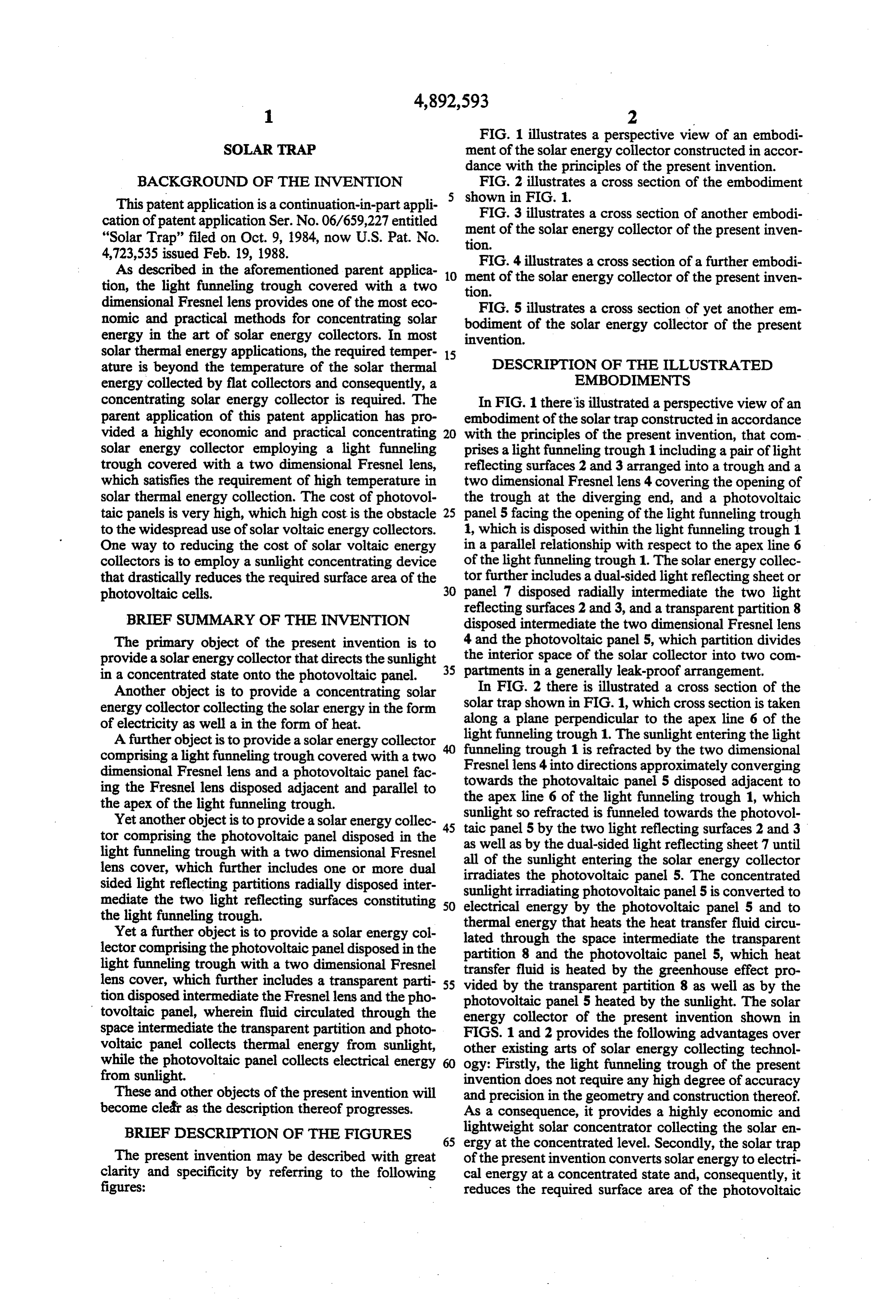
The present invention may be described with great of the present invention converts solar energy to electri clarity and specificity by referring to the following cal energy at a concentrated state and, consequently, it figures: reduces the required surface area of the photovoltaic
Page 4
panel, which drastically lowers the cost of the electric The embodiments of the invention, in which an exclu ity obtained from the solar energy. Thirdly, the solar sive property or privilege is claimed, are defined as trap of the present invention collects thermal energy follows:
from the sunlight at a significantly elevated temperature 1. A solar energy collecting apparatus comprising in and consequently, it greatly improves the versatility of 5 combination:
the solar thermal energy applications. Lastly, the solar (a) a light funneling trough including two flat light trap of the present invention provides electricity as well reflecting surfaces disposed in a face-to-face ar as heat, which dual function provides low initial capital rangement having an oblique angle therebetween; cost, high user convenience and improved operating (b) a two dimensional Fresnel lens covering the open efficiency of the solar collector. The solar trap of the 10 ing of the light funneling trough at the diverging present invention is a perfect solar energy collector for extremity thereof;
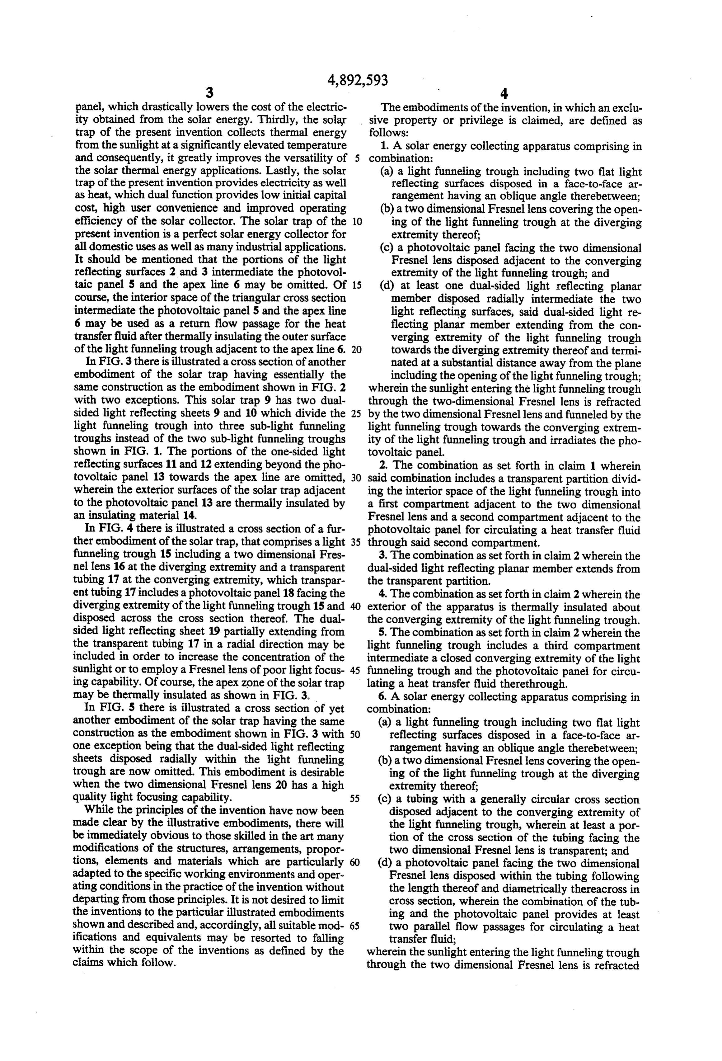
all domestic uses as well as many industrial applications. (c) a photovoltaic panel facing the two dimensional It should be mentioned that the portions of the light Fresnel lens disposed adjacent to the converging reflecting surfaces 2 and 3 intermediate the photovol extremity of the light funneling trough; and taic panel 5 and the apex line 6 may be omitted. Of 15 (d) at least one dual-sided light reflecting planar course, the interior space of the triangular cross section member disposed radially intermediate the two intermediate the photovoltaic panel 5 and the apex line light reflecting surfaces, said dual-sided light re 6 may be used as a return flow passage for the heat flecting planar member extending from the con transfer fluid after thermally insulating the outer surface verging extremity of the light funneling trough of the light funneling trough adjacent to the apex line 6. 20 towards the diverging extremity thereof and termi In FIG. 3 there is illustrated a cross section of another nated at a substantial distance away from the plane embodiment of the solar trap having essentially the including the opening of the light funneling trough; same construction as the embodiment shown in FIG. 2 wherein the sunlight entering the light funneling trough with two exceptions. This solar trap 9 has two dual through the two-dimensional Fresnel lens is refracted sided light reflecting sheets 9 and 10 which divide the 25 by the two dimensional Fresnellens and funneled by the light funneling trough into three sub-light funneling light funneling trough towards the converging extrem troughs instead of the two sub-light funneling troughs ity of the light funneling trough and irradiates the pho shown in FIG. 1. The portions of the one-sided light tovoltaic panel.
reflecting surfaces 11 and 12 extending beyond the pho 2. The combination as set forth in claim 1 wherein tovoltaic panel 13 towards the apex line are omitted, 30 said combination includes a transparent partition divid wherein the exterior surfaces of the solar trap adjacent ing the interior space of the light funneling trough into to the photovoltaic panel 13 are thermally insulated by a first compartment adjacent to the two dimensional an insulating material 14. Fresnel lens and a second compartment adjacent to the In FIG. 4 there is illustrated a cross section of a fur photovoltaic panel for circulating a heat transfer fluid ther embodiment of the solar trap, that comprises a light 35 through said second compartment. funneling trough 15 including a two dimensional Fres 3. The combination as set forth in claim 2 wherein the nel lens 16 at the diverging extremity and a transparent dual-sided light reflecting planar member extends from tubing 17 at the converging extremity, which transpar the transparent partition.
ent tubing 17 includes a photovoltaic panel 18 facing the 4. The combination as set forth in claim 2 wherein the diverging extremity of the light funneling trough 15 and exterior of the apparatus is thermally insulated about disposed across the cross section thereof. The dual the converging extremity of the light funneling trough. sided light reflecting sheet 19 partially extending from 5. The combination as set forth in claim 2 wherein the the transparent tubing 17 in a radial direction may be light funneling trough includes a third compartment included in order to increase the concentration of the intermediate a closed converging extremity of the light sunlight or to employ a Fresnel lens of poor light focus 45 funneling trough and the photovoltaic panel for circu ing capability. Of course, the apex zone of the solar trap lating a heat transfer fluid therethrough. may be thermally insulated as shown in FIG. 3. 6. A solar energy collecting apparatus comprising in In FIG. 5 there is illustrated a cross section of yet combination:
another embodiment of the solar trap having the same (a) a light funneling trough including two flat light construction as the embodiment shown in FIG. 3 with 50 reflecting surfaces disposed in a face-to-face ar one exception being that the dual-sided light reflecting rangement having an oblique angle therebetween; sheets disposed radially within the light funneling (b) a two dimensional Fresnel lens covering the open trough are now omitted. This embodiment is desirable ing of the light funneling trough at the diverging when the two dimensional Fresnel lens 20 has a high extremity thereof;
quality light focusing capability. 55 (c) a tubing with a generally circular cross section While the principles of the invention have now been disposed adjacent to the converging extremity of made clear by the illustrative embodiments, there will the light funneling trough, wherein at least a por be immediately obvious to those skilled in the art many tion of the cross section of the tubing facing the modifications of the structures, arrangements, propor two dimensional Fresnel lens is transparent; and tions, elements and materials which are particularly (d) a photovoltaic panel facing the two dimensional adapted to the specific working environments and oper Fresnel lens disposed within the tubing following ating conditions in the practice of the invention without the length thereof and diametrically thereacross in departing from those principles. It is not desired to limit cross section, wherein the combination of the tub the inventions to the particular illustrated embodiments ing and the photovoltaic panel provides at least shown and described and, accordingly, all suitable mod 65 two parallel flow passages for circulating a heat ifications and equivalents may be resorted to falling transfer fluid;
within the scope of the inventions as defined by the wherein the sunlight entering the light funneling trough claims which follow. through the two dimensional Fresnel lens is refracted
Page 5
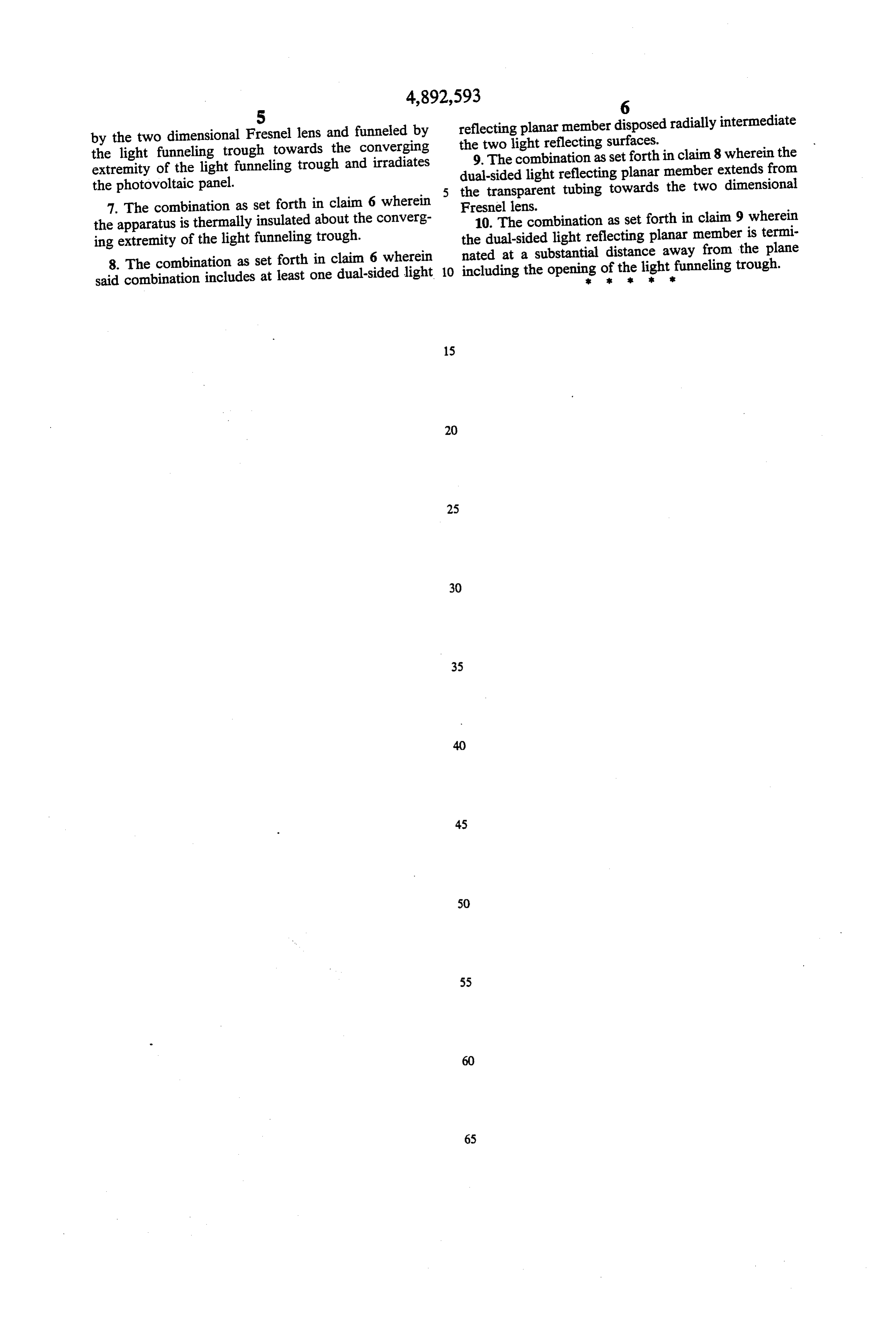
5 reflecting planar member disposed radially intermediate by the two dimensional Fresnel lens and funneled by the two light reflecting surfaces. the light funneling trough towards the converging 9. The combination as set forth in claim 8 wherein the extremity of the light funneling trough and irradiates dual-sided light reflecting planar member extends from the photovoltaic panel. the transparent tubing towards the two dimensional 7. The combination as set forth in claim 6 wherein Fresnel lens.
the apparatus is thermally insulated about the converg 10. The combination as set forth in claim 9 wherein ing extremity of the light funneling trough. the dual-sided light reflecting planar member is termi 8. The combination as set forth in claim 6 wherein nated at a substantial distance away from the plane said combination includes at least one dual-sided light 10 including the openingat ofK theK light
funneling trough.
Provenance
- Collection
- Cited prior art
- Original PDF
- patentimages.storage.googleapis.com →
- Filed
- 1988-01-07
- Pages
- 5
- Method
- pdftotext (the PDF's own text layer) + pdftoppm 300dpi page scans
- Source
- Google Patents bibliographic record
- Granted
- 1990-01-09
- Inventors
- Hyok S. Lew
- Transcribed from
- patentimages.storage.googleapis.com →